

Toro 79104 Parts Catalogue
FORM NO. 3318–278
44” VACUUM BAGGER (INT’L)
Model No.79104 – 6900001 & Up
Parts Catalog

3318–278
ORDERING REPLACEMENT PARTS
To order replacement parts, please supply: the part number, the quantity, and the description of each
part desired.
Contents
Description Page Description Page
Hopper & Chute Assembly 1. . . . . . . . . . . . . . . . . . . .
Blower & Impeller Assembly 2. . . . . . . . . . . . . . . . . .
Idler Assembly 3. . . . . . . . . . . . . . . . . . . . . . . . . . . . . .
Pulley & Shield Assembly 4. . . . . . . . . . . . . . . . . . . .
Bag Assembly 5. . . . . . . . . . . . . . . . . . . . . . . . . . . . . .
Baffle Assembly & Adjusting Link 6. . . . . . . . . . . . . .
Note:
Accessories
Description Model / Parts No. Description Model / Parts No.
Part Description Abbreviations
Part descriptions in this catalog may include the following abbreviations.
Abbreviation Meaning Abbreviation Meaning
AR as required. . . . . . . . . . . . . . . . .
ASM assembly. . . . . . . . . . . . . . . .
CARR carriage. . . . . . . . . . . . . .
DEG degrees. . . . . . . . . . . . . . . .
FH flat head. . . . . . . . . . . . . . . . .
GA gauge. . . . . . . . . . . . . . . . .
HF hex flange. . . . . . . . . . . . . . . . .
HFW hex flange washer. . . . . . . . . . . . . . .
HH hex head. . . . . . . . . . . . . . . . .
HHF hex head flange. . . . . . . . . . . . . . . .
HHST hex head self tapping. . . . . . . . . . . . . . .
HJ hex jam. . . . . . . . . . . . . . . . . .
HOC height-of-cut. . . . . . . . . . . . . . . .
HS hex socket. . . . . . . . . . . . . . . . .
HSBH hex socket button head. . . . . . . . . . . . . .
HSFH hex socket flat head. . . . . . . . . . . . . . .
HSH hex socket head. . . . . . . . . . . . . . . .
HWH hex washer head. . . . . . . . . . . . . . .
HWHTF hex washer head. . . . . . . . . . . . .
thread forming
INC incorporated. . . . . . . . . . . . . . . . .
LH left hand. . . . . . . . . . . . . . . . .
PH pan head. . . . . . . . . . . . . . . . .
PPH Phillips pan head. . . . . . . . . . . . . . . .
PTO power take off. . . . . . . . . . . . . . . .
RH right hand. . . . . . . . . . . . . . . . .
SFH slotted fillister head. . . . . . . . . . . . . . . .
SH square head. . . . . . . . . . . . . . . . .
SHWH slotted hex washer head. . . . . . . . . . . . . .
SPH slotted pan head. . . . . . . . . . . . . . . .
STD standard. . . . . . . . . . . . . . . .
TAP self tapping. . . . . . . . . . . . . . . .
TH truss head. . . . . . . . . . . . . . . . .
TTH Torx truss head. . . . . . . . . . . . . . . .
WH wing head. . . . . . . . . . . . . . . . .
Important Format Explanations
This catalog uses special formats to convey information in illustrations and parts lists. Specifically, one format is
used in conjunction with service assemblies and another with quantities associated with reference numbers.
i
The TORO Company — 1995
All Rights Reserved

3318–278
Service Assemblies
Parts within service assemblies have reference numbers in the form
assembly and Y is a sequential number unique to each part within the service assembly.
For example, a wheel assembly might be identified by reference number 6, the tire by 6:1, the valve by 6:2, and
the wheel by 6:3. When you order the assembly identified by reference number 6, you receive all parts identified
by reference numbers 6:1, 6:2, and 6:3. However, you may also order any part individually.
Reference numbers of this type appear in part lists and as callouts in illustrations.
X:Y. X
is the reference number of the service
Reference Numbers with Quantities
Illustrations may have a quantity in parentheses next to a reference number, in the form
number. Y in parentheses is the quantity of the part identified by the reference number.
For example, the illustration callout 4 (2) indicates that two parts are used in that instance.
X (Y). X
is the reference
ii
(4)
3
(2) 6
13
12
30
16
15
25
(2)1
3
3
3318–278
(4)
(3)
8
(2)
(2)7
5
(4)4
3
(4)
2
(2)
20
21
22
(2) 23
(2)
19
18
17
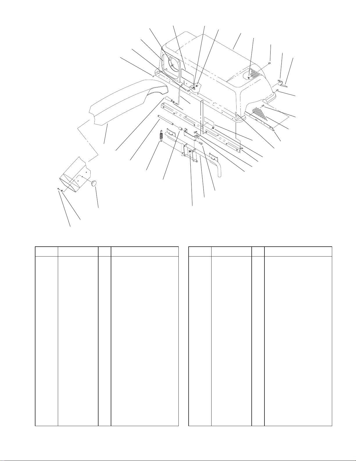
Hopper & Chute Assembly
DescriptionPart No. Qty.Ref. No. DescriptionPart No. Qty.Ref. No.
1 115880 2 Grip
2 115481 2 Latch–Bag Top
3 114439 24 Rivet–Pop
4 9202704 4 Washer–Flat
5 92–1734 1 Top–Bagger
6 321–4 2 Screw–HH
7 3296–42 4 Nut–Lock
8 2412–91 2 Clamp–Cable
9 321–4 2 Screw–HH
10 94–4379 1 ASM–Stiffener
(Incl. Ref. #29)
11 3296–39 2 Nut–Lock
12 114966 1 Clamp–Seal
13 117239 1 Chute–Seal
14 92–1736 1 Support–Screen
15 114969 1 Feeler–Bag
16 3218–1 1 Nut–Jam
17 32144–8 1 Screw–PPH
18 3256–49 1 Washer–Flat
19 233–68 1 Knob
20 79–7240 1 Chute–Discharge
21 118320 1 Handle
22 114960 1 Pin–Spring
23 114962 2 Spring–Extension
24 9790944 2 Spacer
25 114967 1 Bagger–Screen
24
(2)
29
10
9
28
27
26
11
14
3
(9)
(2)
7
26 114955 1 Frame
27 323–6 2 Screw–HH
28 114961 1 Hinge–Bagger Top
29 93–7320 1 Decal–Caution
30 93–7329 1 Decal–Easy Twin
Sheet No.: 4
1
 Loading...