

Page 1

Wheel
FORM NO. 3317–272
Horse
44”
Model No. 79102 – 5900001 & Up
V
for
ac–Bagger
Lawn T
ractor
Operator’s Manual
IMPORTANT: Read this manual carefully. It contains information about your
safety and the safety of others. Also become familiar with the controls and
their proper use before you operate the product.
Page 2
Introduction
We want you to be completely satisfied with your
new product, so feel free to contact your local
Authorized Service Dealer for help with service,
genuine replacement parts, or other information you
may require.
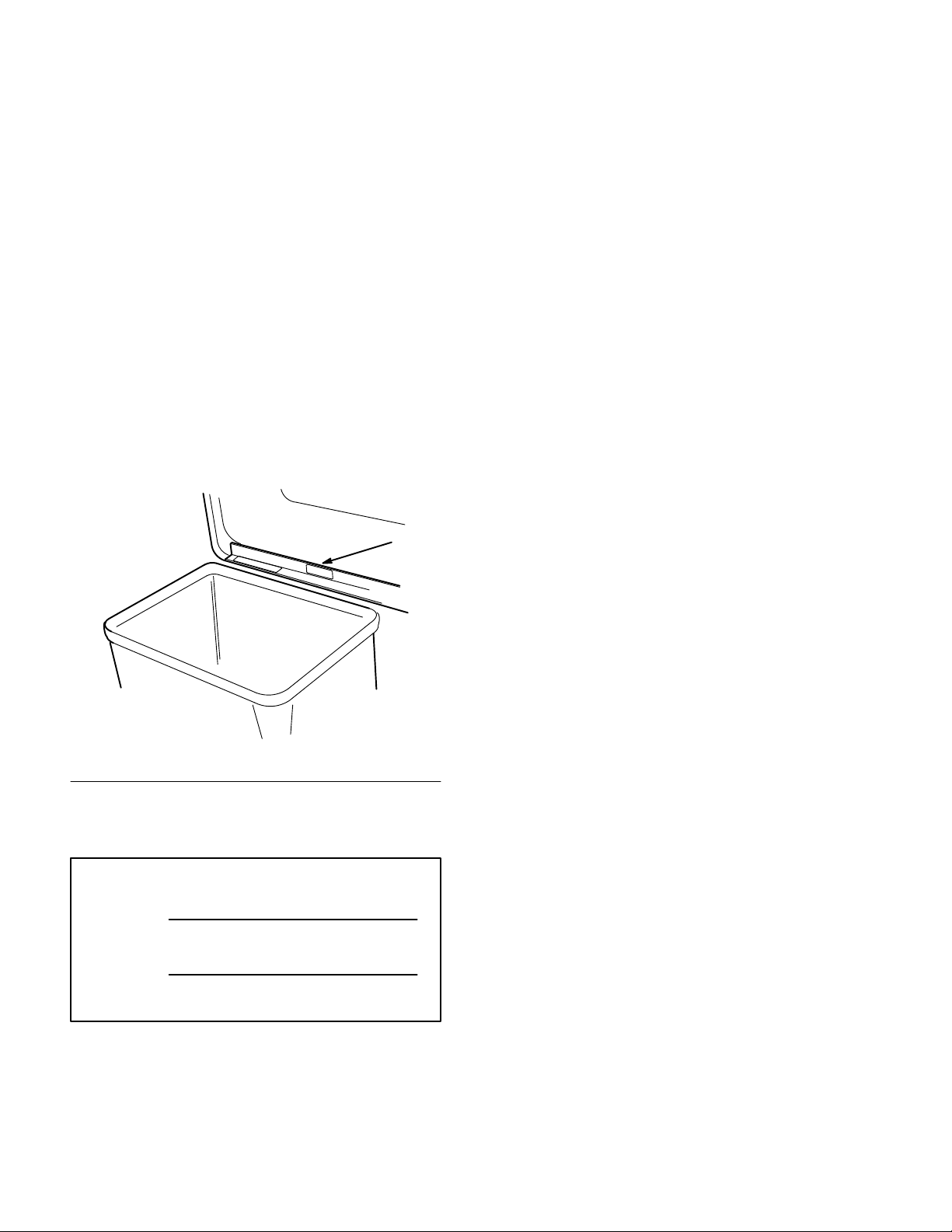
Whenever you contact your Authorized Service
Dealer or the factory, always know the model and
serial numbers of your product. These numbers will
help the Service Dealer or Service Representative
provide exact information about your specific
product. You will find the model and serial number
plate located in a unique place on the product as
shown below
.
1
The warning system in this manual identifies
potential hazards and has special safety messages that
help you and others avoid personal injury, even death.
DANGER, WARNING and CAUTION are signal
words used to identify the level of hazard. However,
regardless of the hazard, be extremely careful.
DANGER signals an extreme hazard that will cause
serious injury or death if the recommended
precautions are not followed.
WARNING signals a hazard that may cause serious
injury or death if the recommended precautions are
not followed.
CAUTION signals a hazard that may cause minor or
moderate injury if the recommended precautions are
not followed.
Two other words are also used to highlight
information. “Important” calls attention to special
mechanical information and “Note” emphasizes
general information worthy of special attention.
1375
1. Model
For your convenience, write the product model and
serial numbers in the space below.
Model No:
Serial No.
and Serial Number Plate
The left and right side of the machine is determined
by sitting on the seat in the normal operator’s
position.
Printed in USA
The TORO Company – 1995
Page 3

Contents
Page
Safety and Instruction Decals 2.
Installation 3
Loose Parts 3
Assembly of the Vac-Bagger 5
Installing Vac-Bagger onto the Tractor 7
Removing the Bagger 12
Operation 17
Using the Full Bag Tester 17
Emptying the Grass Bags 17
. . . . . . . . . . . . . . . . . . . . . . . . . . . . .
. . . . . . . . . . . . . . . . . . . . . . . . .
. . . . . . . . . . . . . . . . . . . . . . . . . . . . . .
. . . . . . . . . . . . .
. . . . . . . . . . .
. . .
. . . . . . . . . . . . . . . . .
. . . . . . . . . . . . . .
. . . . . . . . . . . . . .
Page
Clearing Obstructions From Bagger 18
Operating and Bagging Tips 18
Maintenance 20
Inspecting the Bagger Attachment 20
Inspecting the Mower Blades20. . . . . . . . . . .
Caring for the Grass Bags 20
Cleaning the Bagger Attachment 20
Storing the Bagger Attachment 21
. . . . . . . . . . . . . . . . . . . . . . . . . . . .
. . . . . . . . . . .
. . . . . . . . . . . . .
. . . . .
. . . . . . .
. . . . . . . .
. . . . . . . . .
1
Page 4
Safety
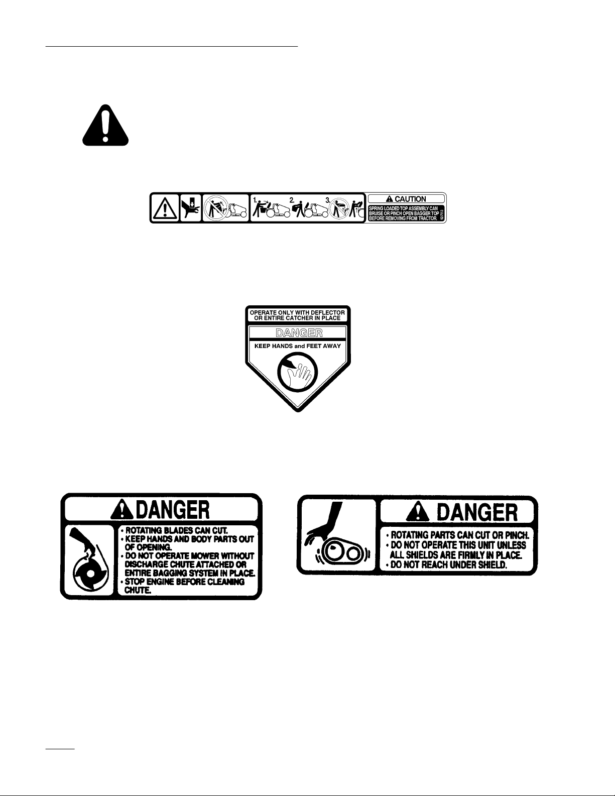
Safety
and Instruction Decals
Safety decals and instructions are easily visible to the operator and are located near
any area of potential danger. Replace any decal that is damaged or lost.
INSIDE BAGGER HINGE FRAME
(Part No. 92-71
MOLDED INT
O BEL
13)
T SHIELD
MOLDED INT
2
O BEL
T SHIELD
MOLDED INT
O BEL
T SHIELD
Page 5

Installation
Loose
Parts
Note: Use the chart below to identify parts used for assembly.
DESCRIPTION QTY. USE
Blade (hi-lift)
Grass baf
Carriage bolt 5/16–18 x 7/8”
Carriage bolt 5/16–18 x 1/2”
Lock nut 5/16
Lock nut (thin) 5/16
Grass baf
Bagging ring
Bolt 1/4–20 x 3/4”
Lock nut 1/4”
Carriage bolt 5/16–18 x 7/8
Carriage bolt 5/16–18 x 2-1/2
Latch tube
Lock nut 5/16
fle-front
fle-rear
3
1
3
1
3
1
1
1
2
2
3
1
1
4
Replace standard lift blades
Install front grass baf
Install rear grass baf
fle
fle and bagging ring
Pivot support
Retainer bracket
Tube
Bolt 5/16–18 x 4-1/2”
Bolt 5/16–18 x 7/8”
Lock nut 5/16
Cover
Indicator rod
Handle
Jam nut 1/4
Clips
Screw 1/4–20 x 3/4”
Lock nut 1/4
Frame assembly
Screw 1/4–20 x 3/4”
Lock nut 1/4
1
1
1
Install blower pivot support
1
2
4
1
1
1
1
2
Assemble the bagger
2
2
1
2
2
3
Page 6

Installation
DESCRIPTION USEQTY.
Blower mounting plate
Blower assembly
Carriage bolt 5/16–18 x 7/8”
Flange nut 5/16
L–support bracket
W
asher 5/16”
Latch
Spacer
Spring
Rubber latch
Flanged spacer
Barbed fastener
Tube
Knob
Screw 1/4–20 x 3/4”
Washer
Pulley
1
1
5
5
1
1
Assemble the blower
1
1
1
1
1
1
1
1
Assemble the tube latch knob
1
1
1
Blower assembly
Belt
Belt cover
Blower belt cover
Washer
Knobs (Lock nut–International)
Quick-attach bracket
Bolt 3/8–16 x 2”
Washer
Spacer
Lock nut 3/8
Hair pin cotter
Bagger top
Grass bags
Operator’
s Manual
1
1
1
1
2
2
1
2
2
2
2
1
1
2
1
Install the blower
Install the bagger assembly
Read before operating
4
Page 7

Installation
Assembly
of the V
ac-Bagger
Assemble the Blower
1. Install the blower mounting plate assembly to
the blower housing with (3) 5⁄16” x 7/8” carriage
bolts and 5⁄16 flange nuts (Fig. 1).
2. Install the L–shaped support bracket inside the
blower housing using a
5
⁄16 washer and 5⁄16 flange nut (Fig. 1). Do not
tighten the flange nut.
3. Pull the L–support bracket up tight against the
inside wall of the blower housing and tighten the
flange nut (Fig. 1).
4. Place spacer and blower latch on top of the
mounting plate and secure with right rear
mounting bolt (Fig. 1).
5. Hook spring between latch and mounting plate
stiffener (Fig. 1).
IMPORTANT: Make sure latch pivots freely.
4
3
5
⁄16” x 7/8” bolt,
8
9
1
4
7
Install the Blower Pulley onto Mower
1. Remove the mower belt cover from the right side
pulley (Fig. 2).
2. Remove the spindle pulley nut. Block the blade
with a piece of wood or some other device to
stop it from turning while you remove the pulley
nut.
3. Thread the new blower pulley onto the spindle
shaft in place of the pulley nut (Fig. 2). Torque
pulley to 70 ft-lbs (95 N.m).
1
4
2
3
2004
Figure 2
1. Belt
cover
2. Nut
Spindle shaft
3.
4.
Blower pulley
5
6
4
1. Blower
2.
3.
4.
5.
mounting plate
Blower housing
Carriage bolt 5/16 x 7/8”
Flange nut 5/16
L –support bracket
Figure 1
6. W
asher 5/16
7. Latch
8. Spacer
9. Spring
4
2
2002
3
5
Page 8

Installation
Assemble the Bagger
1. Install the “full-bag” indicator rod through the
hole in the rubber seal and the slot in the bagger
cover (Fig. 8). Mount the full-bag indicator rod
against the bagger cover using two clips,
1
⁄4 x 3⁄4” screws, and 1⁄4 lock nuts (Fig. 3).
2. Screw the jam nut completely onto the indicator
rod (Fig. 8). Then screw the handle (Fig. 8) close
to the jam nut so you can read the decal from the
operator’s position. Tighten the jam nut up
against the handle to lock it in place.
6
5
2
1
Tractor Bagger Mount
1. Install washers and spacers for bagger mount
outside the tractor frame, using a 3/8 x 2” bolts
and 3/8 lock nuts (Fig. 5).
1848
3
1. Bolt
3/8” x 2”
2
2. Washer
Figure 5
3. Spacer
4.
Lock nut 3/8
1. Indicator
2. Clips
3.
Screw 1/4 x 3/4”
1. Frame
2.
Bolt 1/4 x 3/4”
rod
assembly
3
Figure
2
Figure
4
3
4.
Lock nut 1/4
5.
Jam nut
6. Handle
4
3.
Lock nut 1/4
Assemble the Tube and Knob
1499
1. For use with lawn tractor cut 2” off the bottom
of the discharge tube (Fig. 6).
2. Attach the knob to the middle hole in the
discharge tube and secure with washer and
1/4 x 3/4” screw (Fig. 6).
1
1
2
4
5
1849
Figure 6
1. Cut
off tube
–lawn tractors 2”
2. T
ube center hole
3. Knob
4. Washer
5.
Screw 1/4 x 3/4”
2
3
1981
6
Page 9

Installation
Installing Vac-Bagger onto the
Tractor
Remove the Discharge Chute
1. Park the machine on a level surface, disengage
the blade control (PTO), set the parking brake,
and turn the ignition key to “OFF” to stop the
engine. Remove the key.
2. Lower the mower to its lowest position and
remove mower from tractor. Refer to Mower
Operator’s Manual for instructions.
3. Thoroughly clean mower deck. All debris must
be removed to ensure baffles will fit against
mower properly.
4.
Remove dischar
from the mower (Fig. 7).
Note: Save all parts and hardware for use
ge chute and mounting brackets
when installing discharge chute.
6
Install the Grass Baffles
1. Locate baffle inside front and slide to the left
side of mower. Right end of baffle should be at
or 1/4” inside discharge chute. Using baffle as a
guide drill (4) 11/32” holes (Fig. 8).
2. Install the grass baffle inside front lip of mower,
using 5/16 x 7/8” carriage bolts and 5/16 lock
nuts along the front. At right side use the 1/2”
carriage bolt and thin 5/16 lock nut (Fig. 8).
2
6
4
1. Grass
2.
3.
baf
fle
Drill 1
1/32” hole
Carriage bolt 5/16 x 7/8”
5
Figure 8
2
3
4.
Lock nut 5/16
5.
Carriage bolt 5/16 x 1/2”
6.
Lock nut (thin) 5/16
1
c-2332
2
4
3
5
Figure 7
1. Bracket
2. Spring
3. Discharge
chute
4. Bolt
5.
Carriage bolt
6.
Lock nut
Install Hi-lift Blades
1. Install hi-lift blades from bagger in place of
standard blades. Refer to Mower Operator’s
Manual; Cutting Blade.
1783
3. Install rear grass baffle and grass ring inside
discharge chute area. Secure with 5/16 x 7/8”
carriage bolts and 5/16 lock nuts (Fig. 9). Add
latch tube to outer bolt securing rear baffle
before securing with lock nut (Fig. 9).
1
5
3
4
6
2
Figure 9
1. Rear
2.
3.
4.
grass baf
Grass ring
Latch tube
Carriage bolt 5/16 x 7/8”
fle
8
5
1
7
4
5.
Lock nut 5/16
6.
Carriage bolt 5/16 x 2-1/2”
7.
Screw 1/4 x 3/4”
8.
Lock nut 1/4
1979
7
Page 10

Installation
4. Rotate the blades to make sure they do not hit
the baffles or grass ring. Adjust baf
fles as
required so blades do not hit.
Install the Blower Pivot Support
1. Locate the pivot support on the mower over
square holes near the discharge opening
(Fig. 10).
2. Push the vertical side (front) of the pivot support
against the front of the mower and clamp it
snugly, making sure the top of the pivot support
lies flat on the top of the mower.
3. Secure the pivot support to the top of the mower
with a 5/16 x 4” bolt, spacer tube and
5/16” x 7/8” bolt (from the underside of mower)
and lock nuts (Fig. 10).
4. Secure the pivot bracket to the pivot support
with 5/16 lock nuts (Fig. 10).
3
5
Install the Blower Belt
1. Remove the mower belt cover from the right side
pulley (Fig. 11). Save mounting hardware.
2. Remove the metal plate from the belt cover
(Fig. 11). Save mounting hardware.
Note: Save all parts and hardware for use
when removing blower.
3
1
2005
1. Belt
2.
Metal plate
cover
2
Figure 1
1
3.
Screw (existing)
1
5
6
2
1. Pivot
2.
3.
support
Carriage bolt 5/16 x 4”
Spacer T
ube
4
Figure 10
4.
5.
6.
2017
Carriage bolt 5/16 x 7/8”
Lock nut 5/16
Pivot bracket
3. Slide the blower belt through opening in the belt
cover and place around blower pulley (Fig. 12).
4. Install the belt cover using existing hardware
(Fig. 12).
4
2
1. Belt
2.
Blower belt
1
cover
Figure 12
3.
4.
Blower pulley
Screw (existing)
3
2005
8
Page 11

Installation
5. Install the blower by lowering the pivot pin into
of the pivot support (Fig. 13).
1
2
2014
Figure 13
1. Pivot
pin
2.
Pivot support
6. Open latch and swing the blower out away from
the mower, install the blower belt around idler
and blower pulleys as shown (Fig. 14).
7. With the belt installed, swing the blower toward
the mower until the blower latch locks over the
pin at the back of the mower (Fig. 15).
1
2
2006
Figure 15
1. Blower
latch
2. Pin
Install the Blower Belt Cover
8. Install the blower belt cover using (4) washers
and (2) knobs (Fig. 16). To meet international
safety requirements lock nuts are required.
3
1. Idler
2. T
pulley bracket and
pulley
op side of belt against
bottom pulley
1
3
1
2
2
1839
2
Figure 14
3.
V–side of belt into top
pulley
2003
Figure 16
1. Mower
2. Washer
belt cover
Knob (Lock nuts)
3.
9
Page 12

Installation
Install the Leveling Brackets
1. Install mower onto tractor. Refer to Mower
Operator’s Manual for instructions.
2. Replace the two left side mower leveling
brackets (slotted) with two new leveling brackets
(holes) (Fig. 17). Secure with existing washers
and hair pin cotters (Fig. 17).
Note: Save slotted leveling brackets for use
when blower is removed for side
discharge operation.
Figure 17
1. Slotted
2. Washer
leveling bracket
(2)
3. Hair
pin cotter
1803
Install the Bagger
1. Slide the bottom of the quick-attach bracket
down into the hole in the hitch and hook the
notches onto the spacers located inside the
tractor frame (Fig. 18).
2. Slide the hair pin cotter through the hole at the
bottom of the quick-attach bracket (Fig. 18).
3
1
2
Figure 18
1. Quick-attach
2.
Hole in hitch
bracket
3. Spacers
4.
3. Tip the tractor seat forward.
4
Hair pin cotter
3
2016
3. Check mower level front-to-rear and
side-to–side; refer to Mower Operator’
for instructions.
s Manual
4. Carefully lift the bagger top and slide it onto the
quick-attach bracket (Fig. 19). The bagger top is
easier to install if two people work together.
1
2
Figure 19
1. Bagger
top
2.
Quick-attach bracket
10
Page 13

POTENTIAL
HAZARD
• The hinge frame on the bagger top is
spring-loaded.
WHAT CAN HAPPEN
• If you remove the bagger top when it is
closed (in the down position), the top may
suddenly fly open and you or someone else
may be bruised, pinched, or injured in
another way.
Installation
6. Lower the bagger top onto the bags. Then push
down on both bag retainer handles until they
lock on the bag frame (Fig. 21).
1
HOW TO AV
OID THE HAZARD
• Always open (raise) the bagger top before
you remove or install it on the quick-attach
bracket.
5. Install the bags by sliding the bag frame hooks
onto the retaining brackets (Fig. 20).
1
2
2
Figure 21
1. Bagger
top
2.
Bag retainer handles
7. Move the tractor seat to its normal position.
Mount the Discharge Tube
1. Insert the upper end of the discharge tube into
the bagger top. Slide the lower end of the
discharge tube over the blower discharge
opening (Fig. 22).
2. Hook the rubber latch onto the knob (Fig. 22).
1
2
1376
1. Bag
frame hook
Figure 20
2.
Retaining bracket
1373
1. Rubber
latch
1847
Figure 22
2. Knob
11
Page 14

Installation
Removing
the Bagger
Remove the Discharge Tube
1. Unhook the rubber latch onto the knob (Fig. 23).
2. Slide the lower end of the discharge tube off the
blower discharge opening (Fig. 23). Pull the
upper end of the discharge tube out of the bagger
top.
1
2
1847
3. Remove the hair pin cotter from the hole at the
bottom of the quick-attach bracket (Fig. 26).
4. Carefully lift the bagger top and slide off the
quick-attach bracket (Fig. 25). The bagger top is
easier to remove if two people work together.
1
2
Figure 25
1. Bagger
top
2.
Quick-attach bracket
Figure 23
1. Rubber
latch
2. Knob
Remove the Bagger
1. Tip the tractor seat forward.
2. Raise the bagger top and remove the grass bags
from the bag frame (Fig. 24).
1
2
1376
POTENTIAL
HAZARD
• The hinge frame on the bagger top is
spring-loaded.
WHAT CAN HAPPEN
• If you remove the bagger top when it is
closed (in the down position), the top may
suddenly fly open and you or someone else
may be bruised, pinched, or injured in
another way.
HOW TO AV
OID THE HAZARD
• Always open (raise) the bagger top before
you remove or install it on the quick-attach
bracket.
1. Bagger
12
top
Figure 24
2.
Bag retainer handles
Page 15

Installation
5. Slide the bottom of the quick-attach bracket up
out of the hole in the hitch and unhook from the
spacers located inside the tractor frame (Fig. 26).
3
3
1
2
4
1371
Figure 26
1. Quick-attach
2.
Hole in hitch
bracket
3. Spacers
4.
Hair pin cotter
6. Move the tractor seat to its normal position.
Remove the Blower from the Mower
1. Open latch and swing the blower out away from
the mower, remove the blower belt from idler
and blower pulleys (Fig. 28).
1
3
2
1. Idler
pulley bracket and
pulley
2. T
op side of belt against
bottom pulley
Figure 28
3.
V–side of belt into top
pulley
1839
Remove Blower Belt Cover
7. Remove the blower belt cover by removing (2)
knobs (International lock nuts) and (4) washers
(Fig. 27).
Note: Save all parts and hardware for use
when installing blower.
3
1
2
2
2003
Figure 27
1. Mower
2. Washer
belt cover
Knob (Lock nuts)
3.
2. Remove the blower by lifting the pivot pin out
of the pivot support (Fig. 29).
1
2
2014
Figure 29
1. Pivot
pin
2.
Pivot support
13
Page 16

Installation
Remove the Blower Belt
1. Remove the mower belt cover from the right side
pulley (Fig. 30). Save mounting hardware.
2. Unhook blower belt from blower pulley and
slide the belt out of opening in belt cover
(Fig. 30).
4
2
1. Belt
2.
Blower belt
1
cover
Figure 30
3.
4.
Blower pulley
Screw (existing)
1
2005
Remove the Blower Pivot Support
1. Remove the pivot support and pivot bracket
from the mower (Fig. 32).
Note: Save all parts and hardware for use
when installing blower.
5
1
6
2
4
1. Pivot
2.
3.
support
Pivot bracket
Carriage bolt 5/16 x 7/8”
Figure 32
6
3
4.
Carriage bolt 5/16 x 4”
5.
Spacer tube
6.
Lock nut 5/16
2017
3. Install the metal window onto the belt cover
using existing hardware (Fig. 31).
4. Install the belt cover using existing hardware
(Fig. 31).
3
1
1. Belt
2.
Metal Plate
cover
2
Figure 31
3.
Screw (existing)
2005
Install Standard-lift Blades
1. Install standard-lift blades for side discharging in
place of hi-lift blades. Refer to Mower
Operator’
s Manual; Cutting Blade.
14
Page 17

Installation
Remove the Grass Baffles
1. Remove the grass baffle inside front lip of
mower (Fig. 33).
Note: Install hardware to fill holes in mower.
5
3
1. Grass
2.
3.
baf
fle
Carriage bolt 5/16 x 7/8”
Lock nut 5/16
2. Remove rear grass baffle and grass ring from
inside dischar
4
2
Figure 33
4.
Carriage bolt 5/16 x 1/2”
5.
Lock nut (thin) 5/16
ge chute area (Fig. 34).
1
c-2332
Install the Grass Deflector
1. Install mounting brackets onto the mower with
5/16 x 3/4” carriage bolts and 5/16 lock nuts
(Fig. 35).
1. Place springs into brackets on mower with
hooked ends over raised back (Fig. 35).
2. Align grass deflector with holes in brackets and
spring straight ends in space under hinge and
above deflector (Fig. 35).
3. Secure deflector to bracket with bolts through
grass deflector, springs and brackets. Secure with
lock nuts (Fig. 35).
4. Lift grass deflector and check that it is spring
loaded and pivots freely to the full down
position.
IMPORTANT: Grass deflector must be
spring loaded in the down position. Lift
deflector up to test that it snaps to the full
down position.
6
Note: Save all parts and hardware for use
when installing blower.
5
3
4
6
1. Rear
2.
3.
4.
grass baf
Grass ring
Latch tube
Carriage bolt 5/16 x 7/8”
2
Figure 34
fle
4
5.
Lock nut 5/16
6.
Carriage bolt 5/16 x 2-1/2”
7.
Screw 1/4 x 3/4”
8.
Lock nut 1/4
8
2
5
4
3
1
1
5
7
1. Bracket
1979
2. Spring
3. Grass
deflector
Figure 35
4.
5.
6.
Bolt 3/8 x 2-1/2”
Carriage bolt 5/16 x 3/4”
Lock nut 3/8
1783
15
Page 18

Installation
POTENTIAL
HAZARD
• Without the grass deflector, mulch baffle,
or complete grass catcher assembly
mounted in place, you and others are
exposed to blade contact and thrown
debris.
Mount Mower onto Tractor
1. Install mower onto tractor. Refer to Mower
Operator’s Manual for instructions.
2. Replace the two left side mower leveling
brackets (holes) with two slotted leveling
brackets (Fig. 36). Secure with existing washers
and hair pin cotters (Fig. 36).
WHAT CAN HAPPEN
• Contact with rotating mower blade(s) and
thrown debris will cause injury or death.
HOW TO AV
•
NEVER r
OID THE HAZARD
emove the grass deflector from
the mower because the grass deflector
routes material down toward the turf. If the
grass deflector is ever damaged, replace it
immediately.
• Never put your hands or feet under the
mower.
• Never try to clear discharge area or mower
blades unless you move the power take off
(PTO) to “OFF” and rotate the ignition key
to “OFF.” Also remove the key and pull the
wire off the spark plug(s).
Note: Save (hole) leveling brackets for use
when blower is installed.
Figure 36
1. Leveling
2. Washer
bracket (2)
Hair pin cotter
3.
3. Check mower level front-to-rear and
side-to–side; refer to Mower Operator’
for instructions.
1803
s Manual
16
Page 19

Operation
To Avoid Personal Injury:
• Become familiar with all operating and
safety instructions in the operator’s manual
for your tractor and mower before using
this attachment.
•
Never r
bagger top, or the blower while the engine
is running.
emove the discharge tube, bags,
• Always shut the engine off before clearing
an obstruction from the vac bagging
system.
• Never do maintenance or repairs while the
engine is running.
Using
As grass is cut and blown into the bags, the left bag
fills first, then the right bag. If you overfill the bags,
grass will eventually plug the discharge tube or
elbow.
1. Stop the tractor and apply the brake.
2. To check if both bags are full, periodically raise
the Full Bag T
the full bag tester handle (Fig. 37). If you feel
resistance as you raise the handle, the bags must
be emptied because they are full (Fig. 37).
ester
Emptying
Grass bags can weigh up to 90 lb (41kg) when full.
Be careful when lifting or handling a grass bag that is
full. To empty the grass bags:
1. Stop the tractor, set the parking brake, and
disengage the power take off (PTO) by pushing
the PTO control to OFF (this stops the mower
blades). Shut the engine off before you get off
the tractor.
2. Tip the tractor seat forward.
3. Pull up on both bag retainer handles until they
unlock from the bag frame (Fig. 21). Now open
(raise) the bagger top.
4. Compress debris into the bags. With both hands,
lift up on the bag and unhook it from the
retaining bracket (Fig. 20). Empty the bag.
Repeat for the other bag.
5. Install the bags by sliding the bag frame hooks
onto the retaining brackets (Fig. 20).
6. Lower the bagger top onto the bags. Then push
down on both bag retainer handles until they
lock on the bag frame (Fig. 21).
7. Move the tractor seat to its normal position.
the Grass Bags
2
1 Full
bag tester handle
Figure 37
2
1
1381
Bag full
17
Page 20

Operation
Clearing
Obstructions
From Bagger
1. Stop the tractor, shift into neutral, set the parking
brake, push the PTO control to OFF (this stops
the mower blades), turn the ignition key to OFF
to stop the engine, and remove the key from the
switch.
2. Check the grass bags and empty them if they are
full.
3. Remove and separate the discharge tube and
blower from the bagger top and mower. Using a
stick or similar object, carefully remove and
clear the obstruction from the mower, discharge
tube, blower, and the bagger top.
4. After you remove the obstruction, install the
complete bagger system and resume operation.
Cutting Technique
For best lawn appearance, be sure to slightly overlap
the mower into the previously cut area. This helps
reduce the load on the engine and reduces the chance
of plugging the blower andischarge tube.
Using Bags
Although not required, bags may be inserted into
each cloth grass bag as a liner to collect clippings and
make disposal more convenient (Fig. 38). If you use a
bag liner, remove the filled grass bag and close the
top of the liner. Then pull the liner out the grass bag
or turn the bag upside down while holding the handle
on the bottom of the grass bag (allows liner to slide
out).
2
Operating
Size
Remember that the tractor is longer and wider with
this attachment installed. By turning too sharply in
confined places you may damage the attachment.
Trimming
Always trim with the left side of the mower. Do not
trim with the right side of the mower because you
could damage the bagger’s blower and discharge tube.
Cutting Height
Do not set the mower cutting height too low because
long grass surrounding the mower can prevent air
from getting under the mower and entering the
bagging system. If enough air doesn’t get under the
mower, the bagging system will plug.
Cutting Frequency
Cut the grass often, especially when it grows rapidly.
You will have to cut your grass twice if it gets
excessively long (refer to Bagging Long Grass,
page 19).
and Bagging T
ips
1
1378
Figure 38
1 Cloth
Bagging Speed
Most often you will bag with the tractor throttle in the
FAST position and drive at a normal ground speed.
However, in extremely dry and dusty grass, you may
want to slightly reduce throttle speed and increase
ground speed of the tractor. The bagging system may
plug if you drive too fast and the engine speed gets
too slow. On hills it may be necessary to slow the
tractor’s ground speed. This helps maintain engine
speed and bagging efficiency. Mow down hill
whenever possible.
grass bag
2
Bag (liner)
18
Page 21

POTENTIAL HAZARD
• As the grass bags fill, extra weight is added
to the back of the tractor.
WHAT CAN HAPPEN
• If you stop and start suddenly on hills, you
may lose steering control or the tractor may
tip.
HOW TO AV
OID THE HAZARD
• Do not start or stop suddenly when going
uphill or downhill. Avoid uphill starts.
• If you do stop the tractor when going
uphill, disengage the PTO (stop the mower
blades) by pushing the PTO control to
OFF. Then back down the hill using slow
r
everse speed.
• Do not change speeds or stop on slopes.
Operation
Bagging Long Grass
Excessively long grass is heavy and may not be
propelled completely into the grass bags. If this
happens, the discharge tube and blower may plug. To
avoid plugging the bagging system, mow the grass at
a high height-of-cut, then lower the mower to your
normal cutting height and repeat the bagging process.
Bagging W
Always try to cut grass when it is dry because your
lawn will have a neat appearance. If you must cut wet
grass, use the conventional side discharge feature of
the mower. Several hours later, when the clippings are
dry, install the complete bagger attachment and
vacuum up the grass clippings.
Signs of Plugging
As you are bagging, a small amount of grass
clippings normally blow out the front of the mower.
An excessive amount of clipping blow-out indicates
that the bags are full or the system is plugged.
et Grass
19
Page 22

Maintenance
Inspecting
the Bagger
Attachment
Inspect the bagger attachment after the first ten hours
of operation, and monthly thereafter.
1. Check the blower, discharge tube and the bagger
top. Replace these parts if they are cracked or
broken.
2. Tighten all nuts bolts and screws.
3. Inspect the grass bags for deterioration.
POTENTIAL HAZARD
• The grass bag material may tear, wear, and
eventually deteriorate.
WHAT CAN HAPPEN
• You or bystanders could be severely injured
by flying debris or thrown objects that may
pass through worn or deteriorated grass
bags.
HOW TO AV
• Frequently check the grass bags for holes,
rips, wear, and other deterioration. Do not
wash the grass bags. If the bag has
deterioated, install new grass bags supplied
by the manufacturer of this bagger
attachment.
Inspecting
OID THE HAZARD
the Mower Blades
Caring
1. Washing the grass bags is not recommended.
2. To prevent rapid deterioration of bag material,
POTENTIAL HAZARD
• If you store grass clippings in the bagger
attachment cloth grass bags, under the
right conditions, spontaneous combustion
(a fire-generating pr
without an external source of ignition)
could occur.
WHAT CAN HAPPEN
• If a fire occurs, property could be damaged
and/or someone could be injured.
HOW TO AV
• The cloth grass bags are not storage
containers. Never store grass clippings and
debris in the grass bags.
Cleaning
for the Grass Bags
store the bags so they dry completely after each
use.
ocess that occurs
OID THE HAZARD
the Bagger
Attachment
1. After each use, remove and wash the inside and
outside of the bagger top, discharge tube, blower,
and the underside of the mower, using water
sprayed from a garden hose. Use a mild
automotive detergent to remove stubborn dirt.
1. Inspect the mower blades regularly and
whenever a blade strikes a foreign object.
2. If blades are badly worn or damaged, install new
blades. Refer to your tractor or mower operator’s
manual for complete blade maintenance.
20
2. Make sure you remove matted grass from all
parts.
3. After washing let all parts dry thoroughly. Do
not wash the grass bags.
Page 23

Maintenance
Storing
1. Clean the bagger attachment (refer to Cleaning
the Bagger Attachment, page 20).
2. Inspect the bagger attachment for damage (refer
to Inspecting the Bagger Attachment, page 20).
3. Make sure the grass bags are empty and
thoroughly dry.
4. Store the bagger in a clean, dry place, out of
direct sunlight. This protects the plastic parts and
extends the life of the bagger. If you must store
the bagger outside, cover it with a weatherproof
cover.
the Bagger Attachment
21
 Loading...