

Page 1

ZMaster
®
RidingMower
ForAllZMaster
Setup
LooseParts
Usethechartbelowtoverifythatallpartshavebeenshipped.
FormNo.3375-555RevC
®
RidingMowers
SetupInstructions
ProcedureDescription
1
2
3
4
5
6
7
8
9
10
11
12
13
14
Rearwheels(Woodencrateonly)
Nopartsrequired
Nopartsrequired
Nopartsrequired
Nopartsrequired
Nopartsrequired
J-bolt2
Wingnut2
Hold-downclamp1
Clamp
Wingnut(1/4inch)
Batteryhold-down2
Nopartsrequired
Seat
Seatplate(xedseatsonly)
Flangenuts(3/8inch)—xedseatsonly
Spacers(3/8inch)—xedseatsonly
Flangenuts(3/8inch)—tiltingseatsonly
Longspacers(tilting,deluxeseatsonly)
Shortspacers(tilting,deluxeseatsonly)
Nopartsrequired
Right-controllever1
Left-controllever
Bolt(3/8x1inch)—2areassembled
Nut(3/8inch)—2areassembled
Carriagebolt(3/8x1-1/2inches)
Flangelocknut(3/8inch)
Air-cleanercap1
Hoseclamp1
Qty.
Use
2
–
–
–
–
–
1
2
–
1
1
8
4
4
2
4
–
1
4
4
1
1
Removethemachinefromacrate.
Addfueltothemachine.
Checktheengine-oillevel.
Checkthetirepressure.
Checkthewheellugnuttorque.
Checkthegrassdeector.
Installabattery(Dieselmachinesonly).
Installabattery(Gasolinemachines
only).
Chargethebattery.
Installtheseat(Internationalmachines
usinggasolineonly).
Checktheseatbelt(International
machinesusinggasolineonly).
Installthemotion-controllevers
(Internationalmachinesusinggasoline
only).
Installthelift-assistpedal(International
machinesusinggasolineonly).
Installtheair-cleanercap(International
machinesusinggasolineonly).
©2015—TheToro®Company
8111LyndaleAvenueSouth
Bloomington,MN55420
Registeratwww.T oro.com.
OriginalInstructions(EN)
PrintedintheUSA.
AllRightsReserved
*3375-555*C
Page 2
ProcedureDescription
15
16
17
18
Bolt(1/2x3-1/4inch)
Locknut(1/2inch)
Roll-OverProtectionSystem(ROPS)Kit
Rollbar,rightsection1
Rollbar,leftsection
Rollbar,centersection1
Bolt(3/8x1inch)
Curvedwasher
Flangenut(3/8inch)
Bolt(1/2x3–1/4inch)
Flangenut(1/2inch)
Number2general-purposelithium-base
ormolybdenum-basegrease.(Purchase
separately.)
1tube
Qty.
Use
1
1
1
1
8
8
8
2
2
InstalltheROPShardware(LPG
machinesonly).
InstalltheROPS(International
machinesusinggasolineonly).
InstalltheROPS(Dieselmachines
only).
Checkthemachineforgrease.
19
20
21
Nopartsrequired
Nopartsrequired
Operator'sManual
EngineOwner'sManual
Registrationcard1
Operator-trainingmaterial
Key2
1
RemovingtheMachinefroma
Crate
Partsneededforthisprocedure:
2
Rearwheels(Woodencrateonly)
RemovingaMachinefromaMetalCrate
–
–
1
1
1
Removetheshippingstraps.
Checkthemachinebeforedeliveryto
thecustomer(Allmachines).
Deliveringthemachinetothecustomer
(Allmachines).
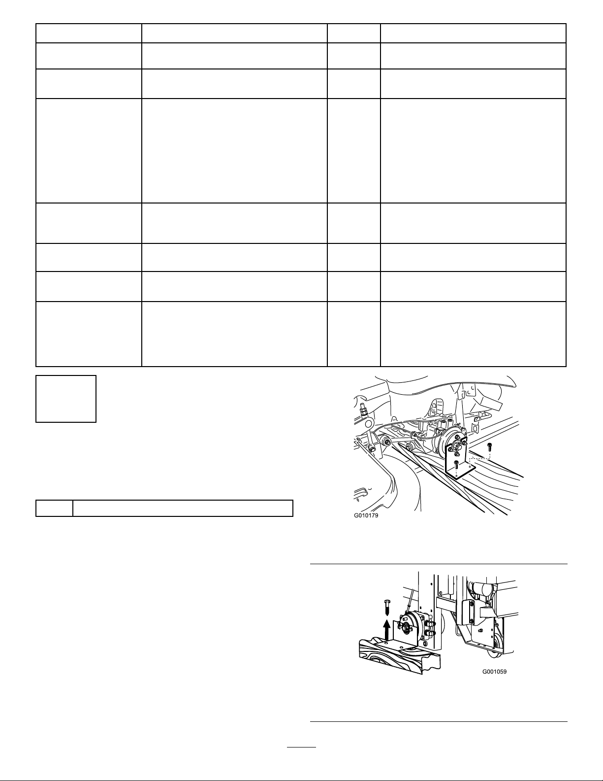
Figure1
GasolineMachineShown
Ifremovingthemachinefromametalcrate,refertothe
Dealer/DistributorPortalforfurtherinformation.
RemovingtheMachinefromaWooden
Crate
1.Removethescrewsholdingtherightangleretaining
platetothecrate.
Figure2
DieselMachineShown
2
Page 3
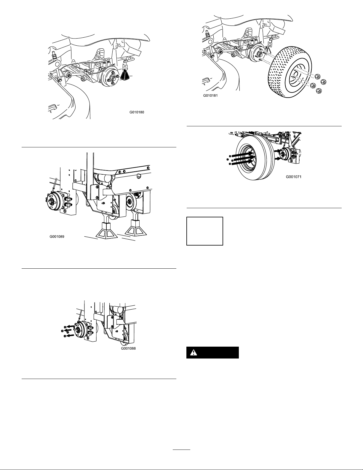
2.Raisethebackofthemachineupandsupportitwith
jack-stands.
Figure3
GasolineMachineShown
Figure6
GasolineMachineShown
Figure7
DieselMachineShown
Figure4
DieselMachineShown
3.Removethewheelnutsfrombothsidesofthevehicle
andremovetherightangleretainingplate.Discardthe
screwsandretainingplate.
Figure5
DieselMachineShown
4.Mountthewheelswiththevalvestemtotheoutside
andsecurethemwiththewheelnutspreviously
removed.
5.Torquethewheelnutsto95ft-lb(128N-m).
6.Removethejackstands.
2
AddingFueltotheMachine
NoPartsRequired
AddingFueltoMachines
Addfueltothemachinebeforestartingit.Refertoyour
Operator’sManualforthecorrectfuelandprocedure.
AddingFueltoLiquidPropaneGas
(LPG)PoweredMachines
CAUTION
Undernocircumstancesshouldyoullpropane
tanksbeyond80%capacity.
Ifyouuseanoverlledtank,itmayresult
inthereleaseofhighlyconcentratedand
extremely-ammableliquidpropane.Refertothe
Safetysectionofthe
1.RemovetheLPG-fueltankfromthefrontofthe.
2.Havethetanklledbytrainedandqualiedpersonnel.
Operator's Man ual
.
3
Page 4
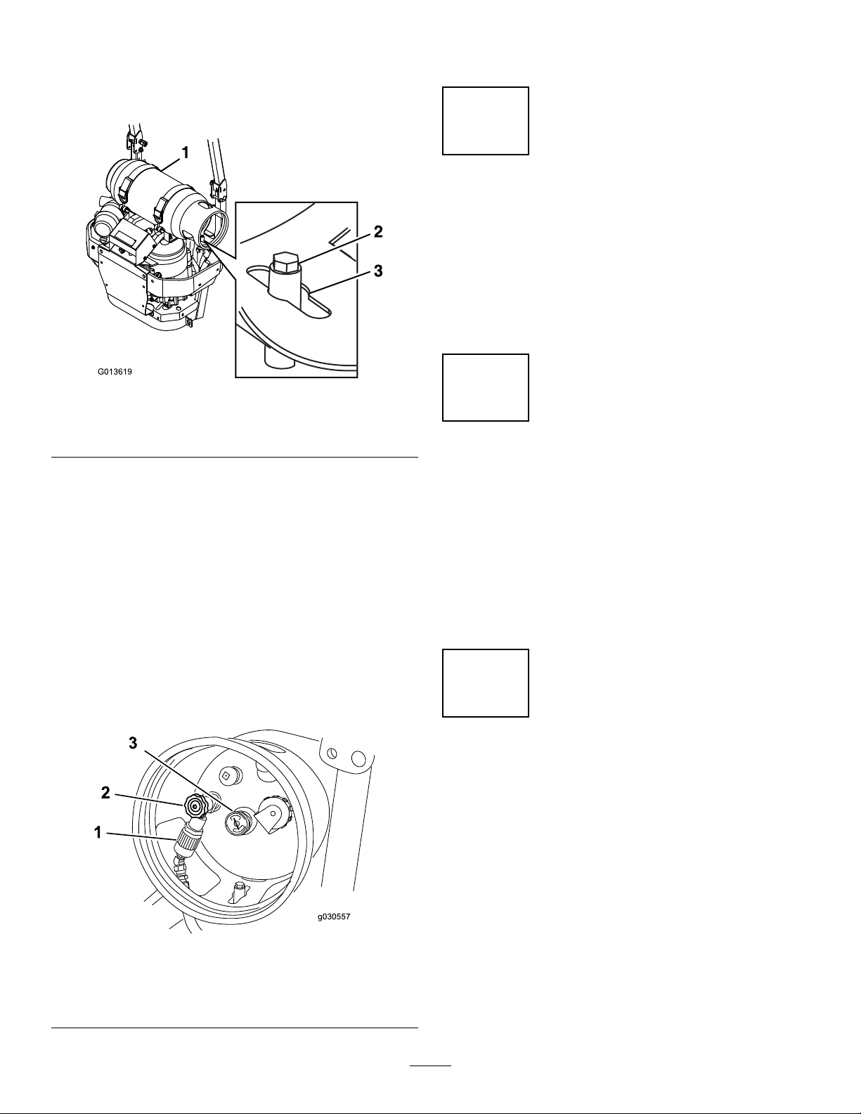
3.Cutthetiessecuringthetankbracketsandmovethem
G013619
g030557
1
2
3
outoftheway.
4.Alignthecenterholeoverthemountingpinthatpoints
straightupontheasshowninFigure8.
Figure8
1.Tankcollar
2.Mountingpin
3.Centerhole
8.CheckforleaksasdescribedintheSafetysectionof
theOperator'sManual.
3
CheckingtheEngine-OilLevel
NoPartsRequired
Procedure
Beforeyoustarttheengineandusethemachine,check
theoillevelintheenginecrankcase;refertoServicingthe
Engine-OilLevelintheOperator'sManual.
4
CheckingtheTirePressure
Important:IfyoudonotinstalltheLPGtank
correctly,thevalvesandgaugesmaynotfunction
properly.
5.Latchthebracketsandensurethatthetankissecurely
fastenedtothemachine.
6.Carefullyconnectthefuelhose.Makesurethehoseis
notkinked.
7.Slowlyopenthefuelvalvetoequalizethepressurein
thetank.Ifyouopenthefuelvalvetooquickly,the
pressurereliefvalveisequippedwithabackpressure
checkvalvethatwillshutoffthefuelsupply.Ifthis
happens,closethefuelvalvecompletelyandwaitve
seconds.Slowlyopenthefuelvalve.
Figure9
NoPartsRequired
Procedure
Pressure:13psi(90kPa)
Note:Checkthetirepressurebeforestartingthemachine.
RefertoyourOperator’sManualforthecorrecttiretype,
correctairpressureneeded,andprocedure.
5
CheckingtheWheelLugNut
Torque
NoPartsRequired
Procedure
Beforeyoustarttheengineandusethemachine,checkthe
wheellugnuttorque;refertoCheckingtheWheelLugNuts
intheOperator'sManual
1.LPGfuelhoseconnection
tting
2.Tankvalve
3.Fuelgauge
4
Page 5
6
1
2
3
2
4
G021 181
4
3
3
7
CheckingtheGrassDeector
NoPartsRequired
Procedure
Ifthereareplastictiesholdingthegrassdeectorup,remove
themandlowerthedeectorintoplace.
WARNING
Anuncovereddischargeopeningcouldallowthe
machinetothrowobjectsintheoperator'sor
bystander'sdirectionandresultinseriousinjuryor
death.Also,contactwiththebladecouldoccur.
Neveroperatethelawnmowerunlessyouinstalla
coverplate,amulchplate,grassdeectororbagger.
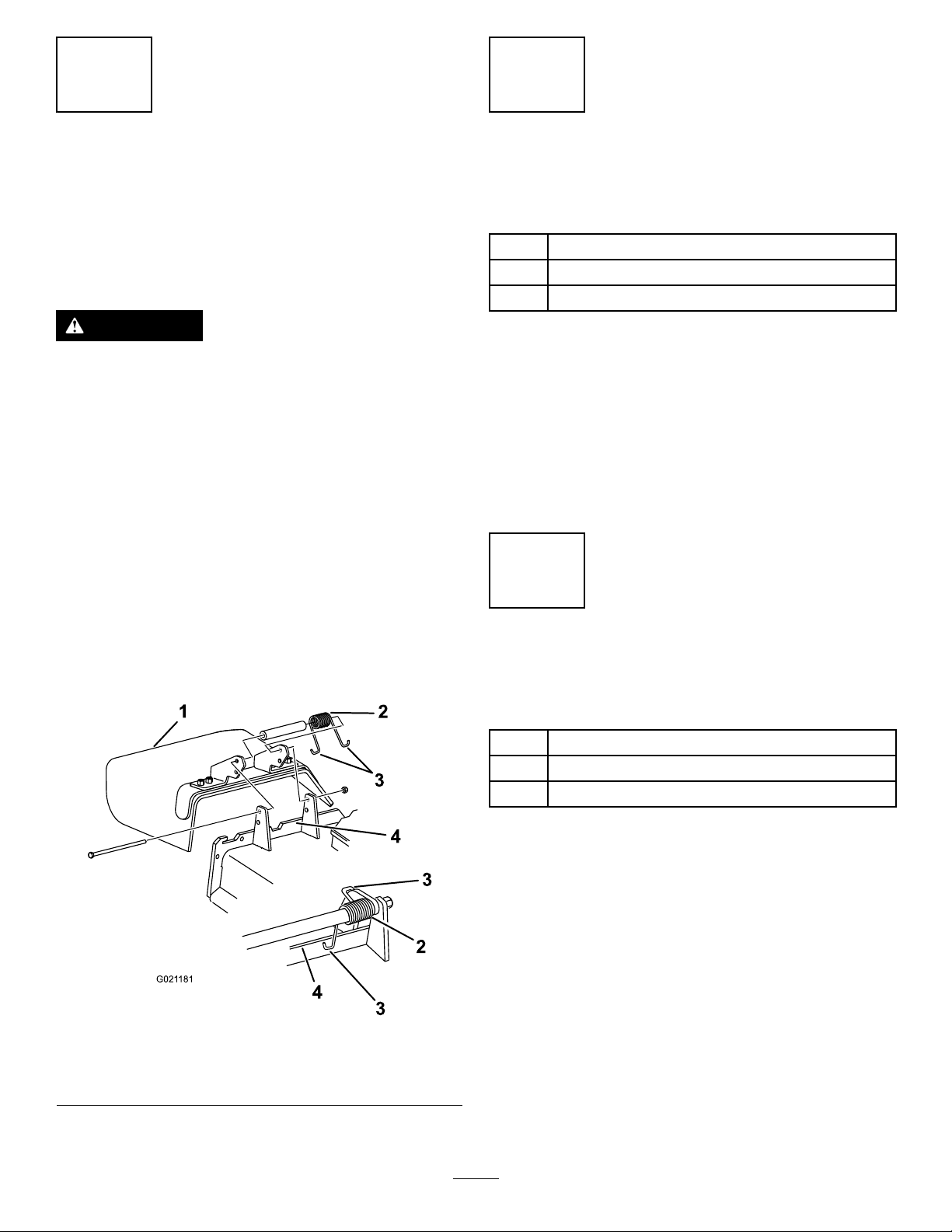
1.Makesurethatoneendofthespringisinstalledbehind
thedeckedgebeforeinstallingtheboltasshownin
Figure10.
2.Placetheotherendofthespringaroundgrassdeector
(Figure10).
InstallingaBattery(Diesel
MachinesOnly)
Partsneededforthisprocedure:
2J-bolt
2Wingnut
1Hold-downclamp
Procedure
Important:Thisprocedureonlyappliestomachines
thatdonotcomewithabatteryinstalled.
Purchasea12Vbatteryandinstallitintothemachine.The
enginerequiresaminimumof540CCA.
Usethehardwareincludedtoinstallthenewbattery.Referto
InstallingtheBatteryintheOperator'sManual.
8
Important:Thegrassdeectormustbefreeto
rotatewithdownwardtension.Liftthedeectorup
tothefullopenpositionandensurethatitrotates
freely,withoutbindingintothefulldownposition.
Figure10
1.GrassDeector3.Endofspring
2.Spring
4.Deckedge
InstallingaBattery(Gasoline
MachinesOnly)
Partsneededforthisprocedure:
1
Clamp
2
Wingnut(1/4inch)
2Batteryhold-down
Procedure
Important:Thisprocedureappliesonlytomachines
thatdonotcomewithabatteryinstalled.
1.Purchasea12Vbattery.
Modelswitha29hpengineandbelowrequireabattery
withaminimumof260CCA.
Modelswitha30hpengineandhigherrequireabattery
withaminimumof340CCA.
2.Locatethebattery-mountinghardwareandinstallit
intothemachine.RefertoInstallingtheBatteryinthe
Operator'sManual.
5
Page 6

9
10
ChargingtheBattery
NoPartsRequired
Procedure
WARNING
Chargingthebatteryproducesgassesthatcan
explodeandcauseseriousinjury.
•Keepcigarettes,sparksandamesawayfrom
thebattery .
•Makesuretheignitionswitchisoff.
•Ventilatewhenchargingorusingthebatteryin
anenclosedspace.
Important:Donotrunthemachinewiththebattery
disconnected;electricaldamagemayoccurtothe
engine.
Chargethebattery.RefertotheOperator'sManualfor
instructions.
InstallingtheSeat
(InternationalMachines
UsingGasolineOnly)
Partsneededforthisprocedure:
1
Seat
1
Seatplate(xedseatsonly)
8
Flangenuts(3/8inch)—xedseatsonly
4
Spacers(3/8inch)—xedseatsonly
4
Flangenuts(3/8inch)—tiltingseatsonly
2
Longspacers(tilting,deluxeseatsonly)
4
Shortspacers(tilting,deluxeseatsonly)
InstallingtheSeatonModelswitha
FixedSeat
1.Removethehydraulic-unitshroudfromthemachine.
Figure11
Figure12
1.Hydraulic-unitshroud2.Bolts
2.Removethe4nutsholdingtheseatplatetothe
machine.Discardthesenuts,theyareusedforshipping
only.
6
Page 7

Figure13
g030558
3.Securetheseatplatetotheseatwith4spacersand4
angenuts(3/8inch).
Figure14
4.Plugtheharnessconnectorintotheseatswitchlocated
undertheseattowardsthefront.
5.Installtheseattothemachineframewith4angenuts
(3/8inch).
Figure15
1.Harnessconnector2.Flangenuts
InstallingtheSeatonModelswitha
TiltingSeat
1.Tilttheseatframeup.
2.Fordeluxeseatsonly,installthespacersasshownin
Figure16.
Figure16
Formachineswithadeluxeseatonly
1.Deluxeseat
2.Longspacer
3.Seatframe
4.Shortspacers
3.Installtheseattotheseatframewith4angenuts(3/8
inch)—Figure17.
7
Page 8

4.Plugtheharnessconnectorintotheseatswitchlocated
3
2
1
g014862
undertheseattowardsthefront.
Figure17
1.Seatswitch
2.Flangenuts
3.Harnessconnector
11
CheckingtheSeatBelt
(InternationalMachinesUsing
GasolineOnly)
NoPartsRequired
Procedure
Important:Ensurethebolttorqueissetbetween49
to61ft-lb(67to83N-m).
Checktheseatbeltangleandtheseatbeltbolttorquebefore
operating.
1.Sideofseat
2.Seatbeltbolt,Settorque
between49to61ft-lb(67
to83N-m)
12
InstallingtheMotion-Control
Levers(InternationalMachines
UsingGasolineOnly)
Partsneededforthisprocedure:
1Right-controllever
1
Left-controllever
4
Bolt(3/8x1inch)—2areassembled
4
Nut(3/8inch)—2areassembled
Figure18
3.47degrees
1.Checktheangleoftheseatbeltcomparedtothe
bottomoftheseat.Theangleneedstobe47degrees.
See(Figure18)
2.Ifneeded,settheseatbelttothecorrectangle.
3.Checkandsetthebolttorquebetween49to61ft-lb
(67to83N-m).
Procedure
1.Rotatethemotion-controlleverstotheupright
position.
2.Looselyinstallthecontrolleversontheinsideofthe
posts,using4boltsand4nuts.
Note:Installthecontrolleversinthetopandmiddle
holesforthehighpositionorthemiddleandbottom
holesforthelowposition,asdesired.
8
Page 9

Figure19
1 2
3
g016346
1.Bolt(3/8x1inch)3.Controllever
2.Handle
4.Nut(3/8inch)
13
InstallingtheLift-AssistPedal
(InternationalMachinesUsing
GasolineOnly)
Partsneededforthisprocedure:
1
Carriagebolt(3/8x1-1/2inches)
1
Flangelocknut(3/8inch)
Procedure
3.Raisetheleversandalignthemtogetherintheneutral
positionandtightenthebolts.
Figure20
1.Ifneeded,loosentheexistingboltandnutforthe
lift-assistpedal.
2.Rotatethelift-assistpedaltothecorrectposition
andinstallthecarriagebolt(3/8x1-1/2inches)and
locknut(3/8inch)(Figure21).Tightenbothbolts.
Note:Ifthemachineisnotproperlytracking,referto
AdjustingtheTrackinginyourOperator'sManual.
Figure21
1.Lift-assistpedal3.Carriagebolt(3/8x1-1/2
inches)
2.Flangelocknut(3/8inch)
9
Page 10

14
InstallingtheAir-CleanerCap
(InternationalMachinesUsing
GasolineOnly)
Partsneededforthisprocedure:
1Air-cleanercap
1Hoseclamp
Procedure
Note:Notallunitscomewithaheavydutyaircleaner.This
procedureonlyappliestomodelsthathaveaheavydutyair
cleaner.
1.Removetheplasticplugortapecoveringtheaircleaner.
Figure23
3.Installtheair-cleanercapontotheaircleanerand
secureitwiththehoseclamp.
Figure22
2.Installthehoseclampontotheair-cleanercap.
Figure24
10
Page 11

15
G013506
1
2 3
16
InstallingtheROPSHardware
(LPGMachinesOnly)
Partsneededforthisprocedure:
1
Bolt(1/2x3-1/4inch)
1
Locknut(1/2inch)
Procedure
Installthebolt(1/2x3-1/4inch)andlocknut(1/2inch)
intotheopenholeintheRoll-OverProtectionSystem
(ROPS)—Figure25.Thiswillpreventtherollbarfrom
hittingthecylinderwhenloweredtothedownposition.
InstallingtheROPS
(InternationalMachines
UsingGasolineOnly)
Partsneededforthisprocedure:
1
Roll-OverProtectionSystem(ROPS)Kit
Procedure
InstalltheRoll-OverProtectionSystem(ROPS)Kit.Follow
theinstructionsincludedwiththeROPSKit.
17
InstallingtheROPS(Diesel
MachinesOnly)
1.Locknut(1/2inch)3.Bolt(1/2x3-1/4inch)
2.ROPS
Figure25
Partsneededforthisprocedure:
1Rollbar,rightsection
1
Rollbar,leftsection
1Rollbar,centersection
8
Bolt(3/8x1inch)
8
Curvedwasher
8
Flangenut(3/8inch)
2
Bolt(1/2x3–1/4inch)
2
Flangenut(1/2inch)
Procedure
1.Looselyinstalltherightandleftrollbarsectiontothe
frame,with8bolts(3/8x1inch),8curvedwashers,
and8angenuts(3/8inch).
Note:Installthecurvedwasherconetowardthebolt
head.
11
Page 12

Figure26
g030555
2.Installthelanyardclipsontothelongbolts(1/2x
3-1/4inch).
Note:Makesurethebenttabpointstowardthehead
ofthebolt.
Figure27
3.Lightlyoiltheendsofthecenterrollbarsection.
4.Looselyinstallthecenterrollbarsectionusing2bolts
(1/2x3-1/4inch)and2angenuts(1/2inch).
Note:Installtheboltsfromtheoutsideoftherollbar.
Note:Installthelanyardtaborientedasshownin
Figure28andpointingforward.
Figure28
5.Raisetherollbarintotheuprightpositionandsecure
itwiththepinsandhairpincotterpinsfastenedtothe
lanyards.
Figure29
6.Torqueallofthelowerfasteners,attachedtothe
machineframe,to30ft-lb(40.7N-m).
7.Tightenthecenterroll-barbolts(1/2x3-1/4inch)so
itrotatesfreelywithsomeresistance.
Note:Nomorethanonethreadshouldbeexposed
outsidethenut.
12
Page 13

19
g030083
RemovingtheShippingStraps
NoPartsRequired
Procedure
Figure30
18
CheckingtheMachinefor
Grease
Partsneededforthisprocedure:
Note:ThisprocedureisonlyformachineswithaMyRide
suspensionsystem.
WARNING
Thespringsarecompressedbytheshippingstraps.
Whenthestrapsarecut,theseatwillraiseup
quicklybyapproximately8.9cm(3-1/2inches).
Note:Ensurethestrapsareremovedbeforeoperatingthe
machine.
™
1tube
Procedure
Beforeyouusethemachine,checkthemachineforgrease;
refertoLubricationintheOperator'sManual.
Number2general-purposelithium-baseor
molybdenum-basegrease.(Purchaseseparately.)
Figure31
13
Page 14

20
CheckingtheMachineBeforeDeliverytotheCustomer(All
Machines)
NoPartsRequired
Procedure
Beforedeliveringthemachinetothecustomer,ensurethatyouperformorhaveperformedtheprocedureslistedinthe
followingtableandinitialeachwhennished.RefertotheOperator'sManualforinstructionsonperformingtheseprocedures.
Initial
Checkthetirepressure.
Checkthelevelofthemachine.
Checkthatallspindlesaregreased.
Checktheengine-oillevel.
Checkthehydraulic-uidlevel.
CheckROPSissecure.
Onliquidcooledmachines,checkthelevelofthecoolantintheradiatorandoverowbottle.
Checktheadjustmentoftheparkingbrake.
Ensurethatthemachinetrackscorrectly;refertotheOperator'sManualfortheadjustmentprocedure.
Checkthesafetyinterlocksystem;refertotheOperator'sManual.
EnsurethatthePTOworks.
Checkallfastenersthatyouinstalledtoensurethattheyaretight.
Whenyounishsettingupthemachine,signanddateinthespaceprovidedbelow:
Signature:
CheckProcedure
Date:
14
Page 15

21
DeliveringtheMachinetotheCustomer(AllMachines)
Partsneededforthisprocedure:
1
Operator'sManual
1
EngineOwner'sManual
1Registrationcard
1
Operator-trainingmaterial
2Key
Procedure
Atdelivery,llinthemodelandserialnumber,completetheitemslistedinthefollowingtable,andinitialeachwhennished.
ModelNo.
SerialNo.
15
Page 16

DealerInitial
CustomerInitialCheckProcedure
Showthecustomerwherethefollowingfeaturesarelocatedandhowtheyfunction:
•
Fueltank
•
Oilllcap/Oildipstick
•
Sparkplug(s)
•
Engine-oillter
•
Engine-oildrain
•
Fuelgauge,valveandhose
•
Airlter
•
Radiatorcoolant(ifapplicable)
•
Hydraulic-uidreservoir
•
Hydrauliclter
•
Battery
•
Ignitionswitch
•
Throttlelever
•
Choke(ifapplicable)
•
Powertakeoffswitch(PTO)
•
Motion-controllevers
•
Parkingbrake
•
Height-of-cut
•
Lift-assistlever(ifapplicable)
•
ZStand®(ifapplicable)
•
Adjustableseat
•
Hydraulic-bypassvalves
•
RolloverProtectionSystem(ROPS)
•
Deck-owbafe
RefertotheOperator'sManualtopointoutsafetyprocedures,operation,and
maintenanceprocedures.
ReviewthewarrantystatementasshownintheOperator'sManual.
Describethepostsaleserviceproceduresforyourstore.
Assistthecustomerinllingoutandmailingtheregistrationcardorregisteronlineat
www.T oro.com
MakesurethatthecustomerreceivestheOperator'sManual,EngineOwner'sManual,
SetUpInstructions,andoperatortrainingmaterial.
MakesurethecustomerknowsthePartsCatalogisavailableatwww.T oro.com.
Assistthecustomerinloadingthemachine.
Note:Whenyou,thedealerrepresentative,havenisheddeliveringthemachinetothecustomer,signanddateinthespace
providebelowandkeepacopyofthispagefordealerrecords.Also,thedealermustremindthecustomertouseafull-width
trailerramptoloadthemachine.
Signature:
Signature:Date:
Date:
16
 Loading...