

Page 1
HighFlowHydraulicsKit
GrandStand
ModelNo.78601—SerialNo.400000000andUp
Note:RetaintheseinstructionswiththeOperator’sManualforthemachine.
ThisproductcontainsachemicalorchemicalsknowntotheStateofCalifornia
tocausecancer,birthdefects,orreproductiveharm.
®
MultiForceMower
Proposition65Warning
WARNING
CALIFORNIA
FormNo.3415-703RevB
InstallationInstructions
Readthisinformationcarefullytolearnhowtooperate
andmaintainyourproductproperlyandtoavoid
injuryandproductdamage.Y ouareresponsiblefor
operatingtheproductproperlyandsafely.
YoumaycontactT orodirectlyatwww.T oro.com
forproductsafetyandoperationtrainingmaterials,
accessoryinformation,helpndingadealer,orto
registeryourproduct.
Wheneveryouneedservice,genuineToroparts,or
additionalinformation,contactanAuthorizedService
DealerorToroCustomerServiceandhavethemodel
andserialnumbersofyourproductready .Figure1
identiesthelocationofthemodelandserialnumbers
ontheproduct.Writethenumbersinthespace
provided.
Safety
SafetyandInstructional
Decals
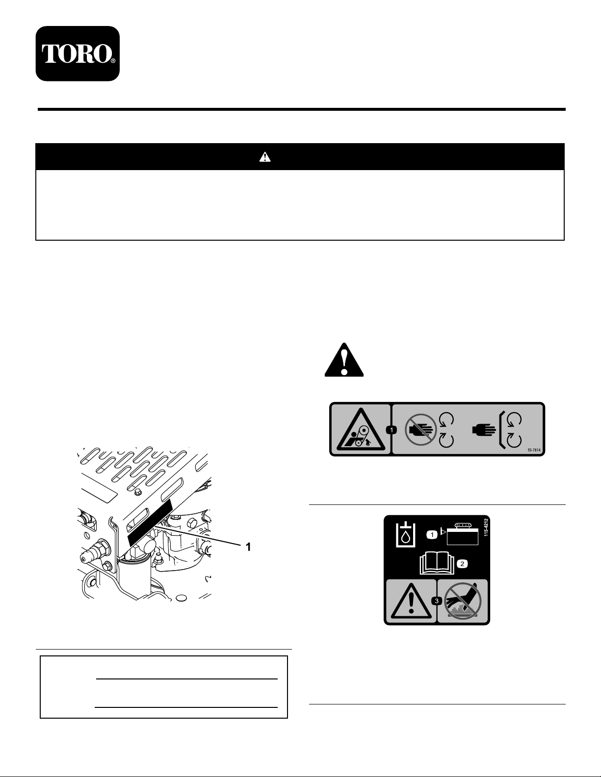
Safetydecalsandinstructionsare
easilyvisibletotheoperatorandare
locatednearanyareaofpotential
danger.Replaceanydecalthatis
damagedormissing.
decal93-7814
93-7814
1.Entanglementhazard,belt—stayawayfrommovingparts.
1.Locationofthemodelandserialnumbers
ModelNo.
SerialNo.
©2017—TheT oro®Company
8111LyndaleAvenueSouth
Bloomington,MN55420
Figure1
Registeratwww.T oro.com.
g214500
decal115-4212
115-4212
1.Hydraulic-uidlevel
2.ReadtheOperator's
Manual.
OriginalInstructions(EN)
PrintedintheUSA
AllRightsReserved
3.Warning—donottouchthe
hotsurface.
*3415-703*B
Page 2
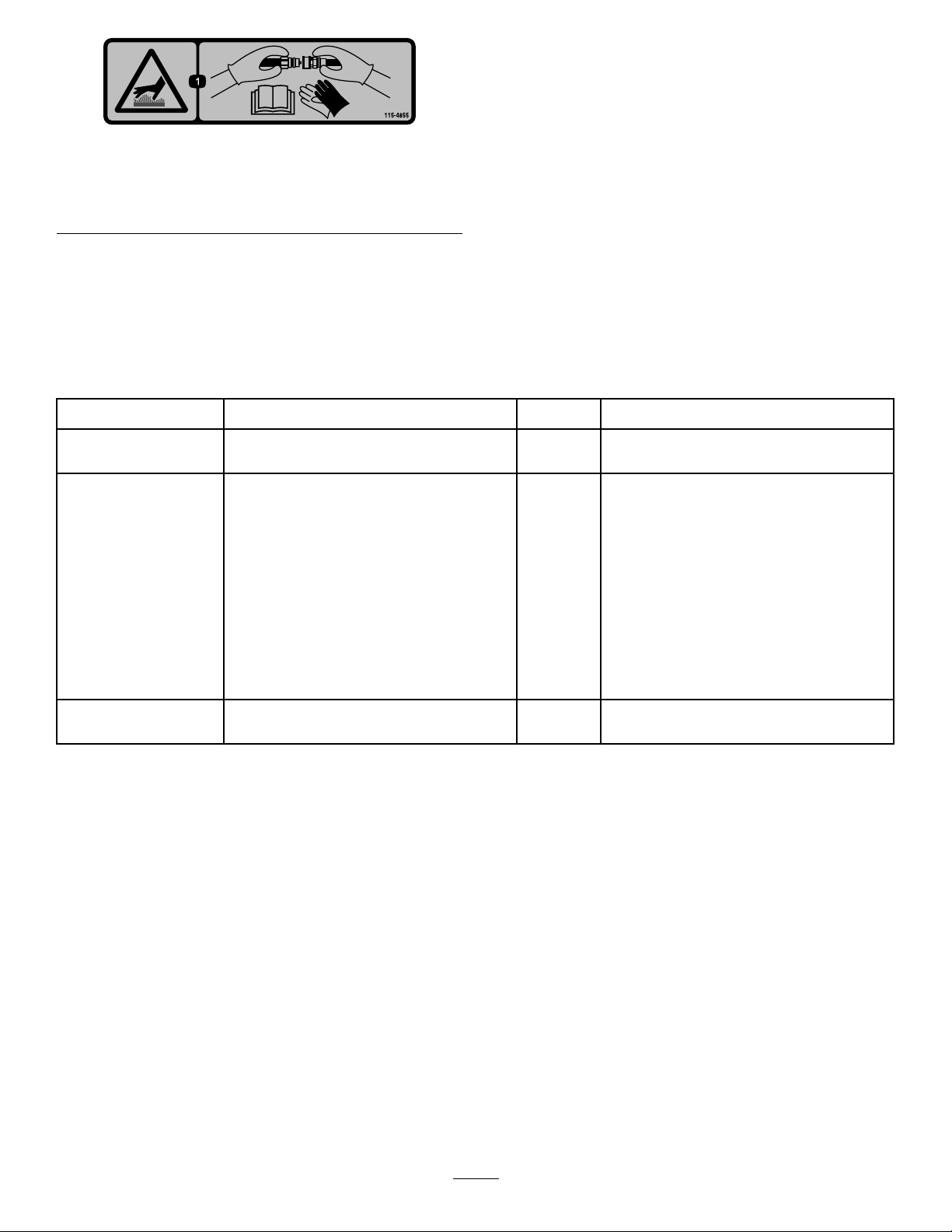
115-4855
1.Hotsurface/burnhazard—wearprotectivegloveswhen
handlingthehydrauliccouplersandreadtheOperator's
Manualforinformationonhandlinghydrauliccomponents.
Installation
LooseParts
Usethechartbelowtoverifythatallpartshavebeenshipped.
decal115-4855
ProcedureDescription
1
2
3
Qty.
Nopartsrequired
High-owassembly
Rearbracket1
Latchpin1
Smallhairpincotter
Largehairpincotter1
Frontbracket1
Carriagebolt(3/8x2-3/4inches)
Spacer
Nut(3/8inch)
Carriagebolt(3/8x1-1/4inches)
Backplate1
Belt1Routethebelt.
–
1
1
2
2
3
1
Preparethemachine.
Installthehigh-owassembly.
Use
Note:Determinetheleftandrightsidesofthemachinefromthenormaloperatingposition.
Important:IfyouareinstallingthiskitontotheGrandstandMultiForceSnowMachine,youalsoneed
toinstallaclutchontothemachine.ContactyourAuthorizedServiceDealer.
2
Page 3
1
PreparingtheMachine
NoPartsRequired
Procedure
1.Parkthemachineonalevelsurface.
2.DisengagethePTO,engagetheparkingbrake,
andmovethemotion-controlleversoutwardto
theNEUTRAL-LOCKposition.
3.Shutofftheengineandremovethekey .
g209230
Figure2
2
InstallingtheHigh-Flow Assembly
Partsneededforthisprocedure:
1
High-owassembly
1Rearbracket
1Latchpin
1
Smallhairpincotter
1Largehairpincotter
1Frontbracket
2
Carriagebolt(3/8x2-3/4inches)
2
Spacer
3
Nut(3/8inch)
1
Carriagebolt(3/8x1-1/4inches)
1Backplate
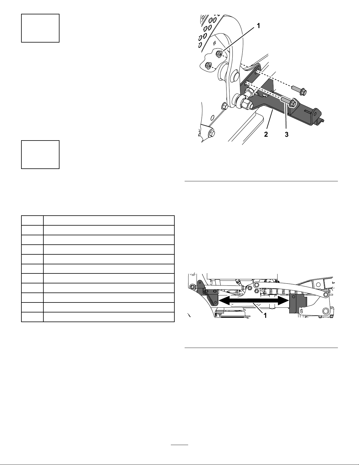
1.Nut(3/8inch)3.Bolt(3/8x1-1/4inches)
2.Rearbracket
3.Usetheboltsandnutsyoujustremovedto
securetherearbracketfromthekitandthefan
shroudtothemachineframe(Figure2).T orque
to41to49N∙m(30to36ft-lb).
4.Looselyinstallthefrontbracketandbackplate
totherighttubeframe,approximately44cm
(17-1/4inches)infrontoftherearbracket
(Figure3),using1carriagebolt(3/8x1-1/4
inches),2carriagebolts(3/8x2-3/4inches),
2spacers,and3nuts(3/8inch)asshownin
(Figure4).
g210668
Figure3
Procedure
Note:Youmayneedasecondpersonorjackstands
toholduptheassemblyasyouinstallittothe
machine.
1.Removethemowerdeck;refertotheOperator’s
Manualforthemachine.
2.Removethe2bolts(3/8x1-1/4inches)and2
nuts(3/8inch)fromtherightsideofthemachine
(Figure2).
Important:Ensurethatthefanshroud
insidetheframedoesnotfallontothe
transaxleasyouremovethehardware.
1.44cm(17-1/4inches)
3
Page 4
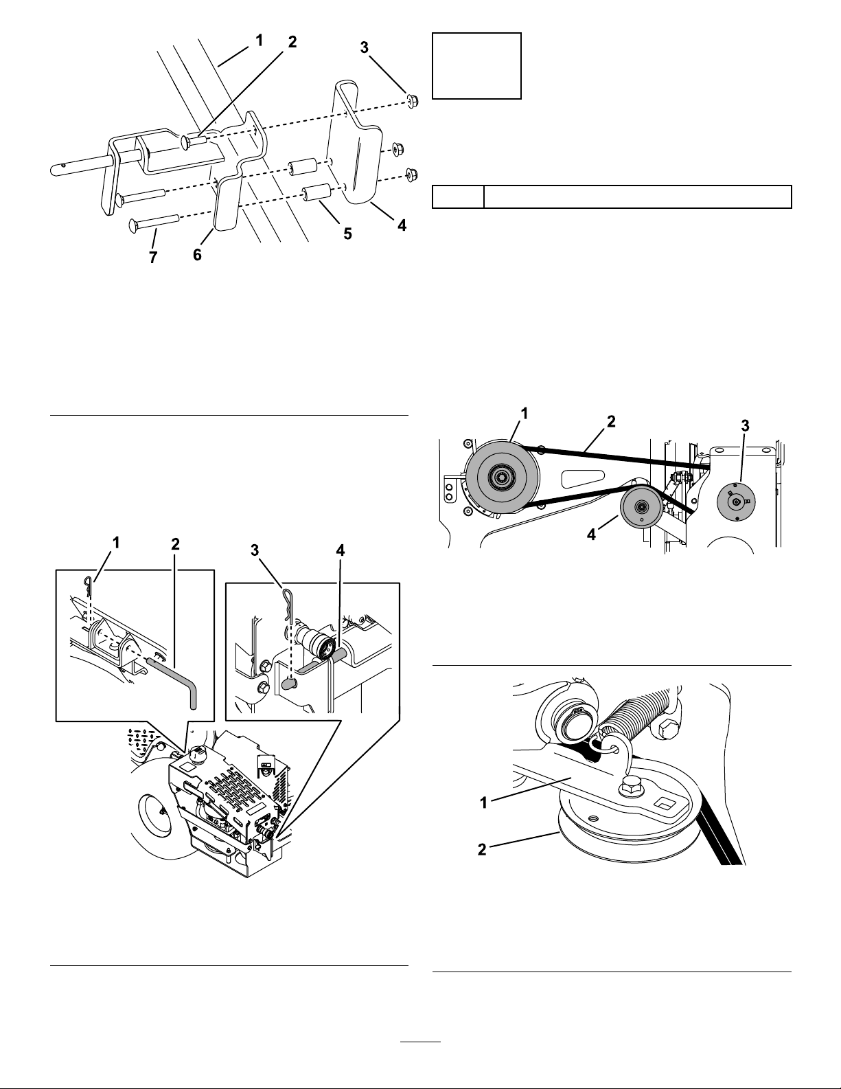
Figure4
1.Tubeframe5.Spacer
2.Carriagebolt(3/8x1-1/4
inches)
3.Nut(3/8inch)7.Carriagebolt(3/8x2-3/4
4.Backplate
6.Frontbracket
inches)
5.Installthehigh-owassemblyontothefrontand
rearbrackets,adjustingthefrontbracketas
necessary.Securetheassemblytorearbracket
usingthesmallhairpincotterandlatchpin,and
secureitonthemountpinofthefrontbracket
usingthelargehairpincotter(Figure5).
3
RoutingtheBelt
Partsneededforthisprocedure:
1Belt
Procedure
g209229
Routethebeltaroundthemachineclutchpulleyand
idlerpulley(Figure6).
Note:Thebeltcomesfromthefactoryalready
attachedtothehigh-owpumppulley.Usearatchet
topullbacktheidlerarmtorelievetensiononthe
spring;youdonotneedtoremovethespringfrom
theidlerpulley(Figure7)
Figure5
1.Smallhairpincotter
2.Latchpin4.Mountpin
3.Largehairpincotter
g209259
Figure6
Viewbelowthemachine
1.Clutchpulley3.High-owpumppulley
2.Belt4.Idlerpulley
g209503
Figure7
Topview
1.Idlerarm2.Idlerpulley
g214199
6.Torquetheboltsonthefrontandrearbrackets
to37to45N∙m(27to33ft-lb).
4
Page 5

Operation
ConnectinganAttachment
Important:DonotengagethemachinePTO
withoutanattachmentconnectedtothehigh-ow
assembly.
Important:Checkthehydraulic-uidlevelbefore
engagingtheattachment;refertoCheckingthe
HydraulicFluid(page6).
1.Parkthemachineonalevelsurface,disengage
thePTO,engagetheparkingbrake,and
movethemotion-controlleversoutwardtothe
NEUTRAL-LOCKposition.
2.Shutofftheengineandremovethekey .
3.Connecttheattachmenthosestothehigh-ow
assemblyquick-disconnectcouplers(Figure8).
Note:Wipeanydirtandcontaminantsfrom
thecouplersbeforeconnectingthemtothe
attachmenthoses.
movethemotion-controlleversoutwardtothe
NEUTRAL-LOCKposition.
2.Shutofftheengineandremovethekey .
3.Disconnectanyattachmentsfromthe
quick-disconnectcouplers.Coverthecouplers.
4.Removethebelt(Figure6).
5.Removethesmallhairpincotterandlatchpin
fromtherearoftheassembly(Figure9).
Figure8
1.Femaleconnector2.Maleconnector
4.Starttheengine.
5.Movetheenginethrottlebetween1/2and3/4
throttleandengagethePTO.
Note:Incoldweather,allowtheattachment
torunforafewminutesbeforeincreasingthe
throttletofullthrottle.
6.Ensurethattheattachmentrunssmoothlyprior
tooperationundernormalworkconditions.
RemovingtheAssembly
g209503
Figure9
1.Smallhairpincotter
2.Latchpin4.Mountpin
6.Removethelargehairpincotterfromthemount
pinonthefrontoftheassembly(Figure9).
g209505
7.Lifttheassemblyoffthefrontandrearbrackets
attachedtothemachine.
3.Largehairpincotter
Note:Ifyouareinstallingthemowerdeck,you
donotneedtoremovethebrackets.
8.Ifyouwillbeinstallingabaggertothemachine,
removethefrontandrearbrackets(seeFigure
2andFigure4).Installtheboltsandnutsfrom
therearbrackettothesecurethefanshroudto
themachine.
Important:Ensurethatthefanshroud
insidetheframedoesnotfallontothe
transaxleasyouremovethehardware.
Note:T oinstalltheassemblyonthemachineagain,
referto2InstallingtheHigh-FlowAssembly(page3).
1.Parkthemachineonalevelsurface,disengage
thePTO,engagetheparkingbrake,and
5
Page 6

Maintenance
RecommendedMaintenanceSchedule(s)
MaintenanceService
Interval
Aftertherst75hours
Beforeeachuseordaily
Every100hours
Every250hours
MaintenanceProcedure
•Changethehydraulicuid,lter,andscreentting.
•Checkthehydraulic-uidlevel.
•Cleandebrisfromthecooler.
•Checkthebelt.
•Changethehydraulicuid,lter,andscreentting.
CheckingtheHydraulic Fluid
ServiceInterval:Beforeeachuseordaily
HydraulicFluidType:T oro®HYPR-OIL™500
hydraulicoil
HydraulicFluidCapacity:4.7L(1.25USgallons)
1.Parkthemachineonalevelsurface,disengage
thePTO,engagetheparkingbrake,and
movethemotion-controlleversoutwardtothe
NEUTRAL-LOCKposition.
2.Shutofftheengineandremovethekey.Allow
themachinetocool.
3.Removethebreathercapandwipeoffthe
dipstickwithacleanrag(Figure10).
4.Insertthedipstickintothetank,butdonotthread
thecap;thenremoveitandchecktheuidlevel
(Figure10).
Note:Theuidlevelshouldbebetweenthe
upperandlowerlinesonthedipstick.
g209517
Figure10
1.Breathercap2.Fluidlevel
5.Iftheuidlevelislow,addhydraulicuidtothe
tankuntilthelevelisbetweentheupperand
lowerlinesonthedipstick(Figure10).
6.Installthebreathercap.
6
Page 7

ChangingtheHydraulic Fluid,Filter,andScreen Fitting
ServiceInterval:Aftertherst75hours
Every250hours/Yearly(whichevercomesrst)
1.Parkthemachineonalevelsurface,disengage
thePTO,engagetheparkingbrake,and
movethemotion-controlleversoutwardtothe
NEUTRAL-LOCKposition.
2.Shutofftheengineandremovethekey.Allow
themachinetocool.
WARNING
Hothydraulicuidcancausesevere
burns.
Allowthehydraulicuidtocoolbefore
performinganymaintenanceonthe
hydraulicsystem.
3.Placeadrainpanunderthe90-degreetting
(Figure1 1).
Figure12
1.Screentting
7.Installthenewscreenttingtothetank(Figure
12).T orquethettingto79to98N∙m(58to72
ft-lb)
8.Installthetubetothescreenttingandpump
(Figure12).
2.Tube
g209573
Figure11
Viewfromtheleftsideoftheassembly
1.90-degreetting2.Hydrauliclter
4.Removethehosefromthettingandallowthe
uidtodrain.
5.Installthehosetothetting.
9.Torquetheendsofthetubeto45to56N∙m(33
to41ft-lb).
10.Removethehydrauliclter(Figure1 1).
11.Lubricatethenewltergasketandllthelter
withhydraulicuid.
12.Ensurethatthelter-mountingareaisclean
andscrewthelteronuntilthegasketcontacts
themountingplate;thentightenthelteran
additional1/10to1/4turn(Figure11).
13.Fillthehydraulictankwithuid;refertoChecking
theHydraulicFluid(page6).
g209562
14.Starttheengineandletitrunwithanattachment
connectedforabout2minutestopurgeairfrom
thesystem.
15.Shutofftheengineandcheckforleaks.
6.Removethetubeandscreenttingfromthetank
andpump(Figure12).Discardthescreentting.
7
Page 8

WARNING
ReplacingtheBelt
Hydraulicuidescapingunderpressure
canpenetrateskinandcauseinjury.
Fluidinjectedintotheskinmustbe
surgicallyremovedwithinafewhoursby
adoctorfamiliarwiththisformofinjury;
otherwise,gangrenemayresult.
•Keepyourbodyandhandsawayfrom
pinholeleaksornozzlesthateject
high-pressurehydraulicuid.
•Usecardboardorpapertond
hydraulicleaks;neveruseyour
hands.
CleaningDebrisfromthe HydraulicCooler
ServiceInterval:Beforeeachuseordaily
1.Parkthemachineonalevelsurface,disengage
thePTO,engagetheparkingbrake,and
movethemotion-controlleversoutwardtothe
NEUTRAL-LOCKposition.
2.Shutofftheengineandremovethekey .
3.Removeanydebrisbuildupfromthehydraulic
coolerandpumpfanshroud(Figure13).
Note:Youmayusepressurizedairtohelp
removedebristhataredifculttoreach.
ServiceInterval:Every100hours
Signsofawornbeltincludesqueakingwhenthebelt
isrotating,afrayedbeltedge,burnmarks,andcracks.
Replacethedeckbeltifanyoftheseconditionsare
evident.
1.Parkthemachineonalevelsurface,disengage
thePTO,engagetheparkingbrake,and
movethemotion-controlleversoutwardtothe
NEUTRAL-LOCKposition.
2.Shutofftheengineandremovethekey .
3.Removethebeltfromthepulleys(Figure14).
g209259
Figure14
1.Clutchpulley3.High-owpumppulley
2.Belt4.Idlerpulley
4.Installthenewbeltaroundthemachineclutch
pulley,idlerpulley,andhigh-owpumppulley
(Figure14).
1.Hydrauliccooler
Note:Usecarenottocutortwistthebeltas
youslideitunderthepumppulleyandframe.
Youdonotneedtoremovethespringfromthe
idlerpulley .
g209576
Figure13
2.Pumpfanshroud
8
Page 9

Notes:
Page 10

Notes:
Page 11

Notes:
Page 12

TheToroWarranty
ALimitedW arranty(seewarrantyperiodsbelow)Contractor
Landscape
Equipment(LCE)
RidingProduct
ConditionsandProductsCovered
TheT oroCompanyanditsafliate,ToroW arrantyCompany ,pursuanttoanagreement
betweenthem,jointlypromisetorepairtheT oroProductslistedbelowifdefectivein
materialsorworkmanship.
Thefollowingtimeperiodsapplyfromtheoriginaldateofpurchase:
ProductsWarrantyPeriod
GrandStand
•Engines
ZMaster
•Engines
ZMaster
•Engines
ZMaster
•Engines
ZMaster
•Engines
ZMaster
•Engines
TITANHD1500Series
3
®
3
®
3
®
3
®
3
®
3
®
3000SeriesMowers
5000SeriesMowers
6000SeriesMowers
7000SeriesMowers
8000SeriesMowers
Mowers
5yearsor1,200hours
3years
5yearsor1,200hours
3years
5yearsor1,200hours
3years
5yearsor1,400hours
3years
4yearsor1,200hours
2years
2years
3years
4yearsor500Hours
2
2
2
2
2
2
•EnginesToro–4yearsor500hours
TITANHD2000Series
•Engines
TITANHD2500Series
•Engines
3
Kohler–3years
4yearsor1000Hours
4yearsor750Hours
3
Kawasaki–3years
2
2
AllMowers
•Battery90daysPartsandLabor
1yearPartsonly
•BeltsandTires90days
•Attachments1year
1
Residentialusemeansuseoftheproductonthesamelotasyourhome.Useatmorethanone
locationisconsideredcommercialuseandthecommercialwarrantywouldapply.
2
Whicheveroccursrst.
3
SomeenginesusedonToroProductsarewarrantedbytheenginemanufacturer.
OwnerResponsibilities
YoumustmaintainyourT oroProductbyfollowingthemaintenanceprocedures
describedintheOperator'sManual.Suchroutinemaintenance,whetherperformedby
adealerorbyyou,isatyourexpense.
InstructionsforObtainingWarrantyService
IfyouthinkthatyourT oroProductcontainsadefectinmaterialsorworkmanship,
followthisprocedure:
1.ContactanyAuthorizedT oroServiceDealertoarrangeserviceattheir
dealership.T olocateadealerconvenienttoyou,accessourwebsiteat
www.T oro.com.Youmayalsocallthenumberslistedinitem#3tousethe
24-hourT oroDealerlocatorsystem.
2.Bringtheproductandyourproofofpurchase(salesreceipt)totheService
Dealer.Thedealerwilldiagnosetheproblemanddetermineifitiscovered
underwarranty.
3.IfforanyreasonyouaredissatisedwiththeServiceDealer’sanalysisorwith
theassistanceprovided,contactusat:
ToroWarrantyCompany
CustomerCareDepartment,RLCDivision
811 1LyndaleAvenueSouth
Bloomington,MN55420-1196
888-865-5676(U.S.Customers)
888-865-5691(Canadacustomers)
ItemsandConditionsNotCovered
Thereisnootherexpresswarrantyexceptforspecialemissionsystemcoverage
andenginewarrantycoverageonsomeproducts.Thisexpresswarrantydoesnot
coverthefollowing:
•Costofregularmaintenanceserviceorparts,suchaslters,fuel,lubricants,oil
changes,sparkplugs,airlters,bladesharpeningorwornblades,cable/linkage
adjustments,orbrakeandclutchadjustments
•Componentsfailingduetonormalwear
•Anyproductorpartwhichhasbeenaltered,misused,neglected,orrequires
replacementorrepairduetoaccidentsorlackofpropermaintenance
•Pickupanddeliverycharges
•RepairsorattemptedrepairsbyanyoneotherthananAuthorizedToroService
Dealer
•Repairsnecessaryduetofailuretofollowrecommendedfuelprocedure(consult
Operator'sManualformoredetails)
–Removingcontaminantsfromthefuelsystemisnotcovered
–Useofoldfuel(morethanonemonthold)orfuelwhichcontainsmorethan
10%ethanolormorethat15%MTBE
–Failuretodrainthefuelsystempriortoanyperiodofnon-useoverone
month
GeneralConditions
AllrepairscoveredbythesewarrantiesmustbeperformedbyanAuthorizedToro
ServiceDealerusingT oroapprovedreplacementparts.
NeitherTheToroCompanynorT oroWarrantyCompanyisliableforindirect,
incidentalorconsequentialdamagesinconnectionwiththeuseoftheToro
Productscoveredbythiswarranty,includinganycostorexpenseofproviding
substituteequipmentorserviceduringreasonableperiodsofmalfunctionor
non-usependingcompletionofrepairsunderthiswarranty .
Allimpliedwarrantiesofmerchantability(thattheproductistforordinaryuse)
andtnessforuse(thattheproductistforaparticularpurpose)arelimitedto
thedurationoftheexpresswarranty .
Somestatesdonotallowexclusionsofincidentalorconsequentialdamages,
orlimitationsonhowlonganimpliedwarrantylasts,sotheaboveexclusions
andlimitationsmaynotapplytoyou.
Thiswarrantygivesyouspeciclegalrights,andyoumayalsohaveotherrights
whichvaryfromstatetostate.
CountriesOtherthantheUnitedStatesorCanada
CustomerswhohavepurchasedT oroproductsoutsidetheUnitedStatesorCanadashouldcontacttheirToroDistributor(Dealer)toobtainguaranteepoliciesforyourcountry ,
province,orstate.IfforanyreasonyouaredissatisedwithyourDistributor'sserviceorhavedifcultyobtainingguaranteeinformation,contacttheT oroimporter.Ifallother
remediesfail,youmaycontactusatT oroWarrantyCompany .
AustralianConsumerLaw:AustraliancustomerswillnddetailsrelatingtotheAustralianConsumerLaweitherinsidetheboxoratyourlocalToroDealer.
374-0252RevK
 Loading...