

Page 1

BlowerKit
FormNo.3424-338RevB
GrandStand
ModelNo.78593—SerialNo.402860000andUp
®
MultiForceMower
Registeratwww.T oro.com.
OriginalInstructions(EN)
*3424-338*B
Page 2
WARNING
CALIFORNIA
Proposition65Warning
Useofthisproductmaycauseexposure
tochemicalsknowntotheStateof
Californiatocausecancer,birthdefects,
orotherreproductiveharm.
Introduction
Thisblowerisintendedtobeusedbyprofessional,
hiredoperators.Itisprimarilydesignedtousewind
powertoquicklyclearlargeareasofunwanteddebris
onwell-maintainedlawns,parks,golfcourses,sports
elds,andoncommercialgrounds.
Readthisinformationcarefullytolearnhowtooperate
andmaintainyourproductproperlyandtoavoid
injuryandproductdamage.Youareresponsiblefor
operatingtheproductproperlyandsafely .
YoumaycontactT orodirectlyatwww.Toro.com
forproductsafetyandoperationtrainingmaterials,
accessoryinformation,helpndingadealer,orto
registeryourproduct.
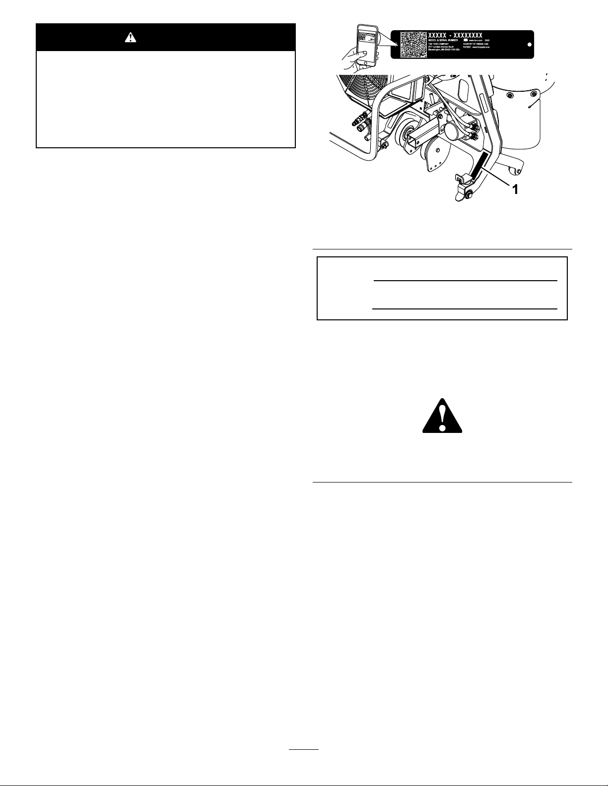
Wheneveryouneedservice,genuineToroparts,or
additionalinformation,contactanAuthorizedService
DealerorToroCustomerServiceandhavethemodel
andserialnumbersofyourproductready.Figure1
identiesthelocationofthemodelandserialnumbers
ontheproduct.Writethenumbersinthespace
provided.
Important:Withyourmobiledevice,youcan
scantheQRcodeontheserialnumberdecal(if
equipped)toaccesswarranty,parts,andother
productinformation.
g246145
Figure1
1.Locationofthemodelandserialnumbers
ModelNo.
SerialNo.
Thismanualidentiespotentialhazardsandhas
safetymessagesidentiedbythesafety-alertsymbol
(Figure2),whichsignalsahazardthatmaycause
seriousinjuryordeathifyoudonotfollowthe
recommendedprecautions.
g000502
Figure2
1.Safety-alertsymbol
Thismanualuses2wordstohighlightinformation.
Importantcallsattentiontospecialmechanical
informationandNoteemphasizesgeneralinformation
worthyofspecialattention.
©2018—TheToro®Company
8111LyndaleAvenueSouth
Bloomington,MN55420
Contactusatwww.Toro.com.
2
PrintedintheUSA
AllRightsReserved
Page 3

Contents
Safety
Safety.......................................................................3
GeneralSafety...................................................3
SafetyandInstructionalDecals..........................4
Setup........................................................................5
1PreparingtheMachine.....................................5
2InstallingtheWheelWeightKit
(Optional)........................................................5
3PositioningtheCasterWheels.........................5
4RemovingtheRightFanGuard........................6
5InstallingtheBlower.........................................7
Operation................................................................10
OperationSafety..............................................10
OperatingtheBlower........................................10
UsingtheKickstand...........................................11
RemovingtheBlower........................................13
OperatingTips.................................................15
Maintenance...........................................................16
MaintenanceSafety..........................................16
CheckingtheBelts............................................16
ReplacingtheBlowerBelt.................................16
ReplacingtheClutchBelt..................................17
CheckingtheHydraulicHoses..........................17
RemovingDebrisfromtheMachine..................17
GeneralSafety
Thisproductiscapableofthrowingobjects.Always
followallsafetyinstructionstoavoidseriouspersonal
injury.
Usingthisproductforpurposesotherthanitsintended
usecouldprovedangeroustoyouandbystanders.
•Readandunderstandthecontentsofthis
Operator’sManualbeforestartingtheengine.
•Useyourfullattentionwhileoperatingthe
machine.Donotengageinanyactivitythat
causesdistractions;otherwise,injuryorproperty
damagemayoccur.
•Donotputyourhandsorfeetnearmoving
componentsofthemachine.
•Donotoperatethemachinewithoutallguards
andothersafetyprotectivedevicesinplaceand
workingonthemachine.
•Keepclearofanydischargeopening.Keep
bystandersandpetsasafedistanceawayfrom
themachine.
•Keepchildrenoutoftheoperatingarea.Never
allowchildrentooperatethemachine.
•Stopthemachine,shutofftheengine,andremove
thekeybeforeservicing,fueling,orunclogging
themachine.
Improperlyusingormaintainingthismachinecan
resultininjury.T oreducethepotentialforinjury,
complywiththesesafetyinstructionsandalways
payattentiontothesafety-alertsymbol
meansCaution,Warning,orDanger—personalsafety
instruction.Failuretocomplywiththeseinstructions
mayresultinpersonalinjuryordeath.
Youcanndadditionalsafetyinformationwhere
neededthroughoutthisOperator’sManual.
,which
3
Page 4
SafetyandInstructional
Decals
Safetydecalsandinstructionsare
easilyvisibletotheoperatorandare
locatednearanyareaofpotential
danger.Replaceanydecalthatis
damagedormissing.
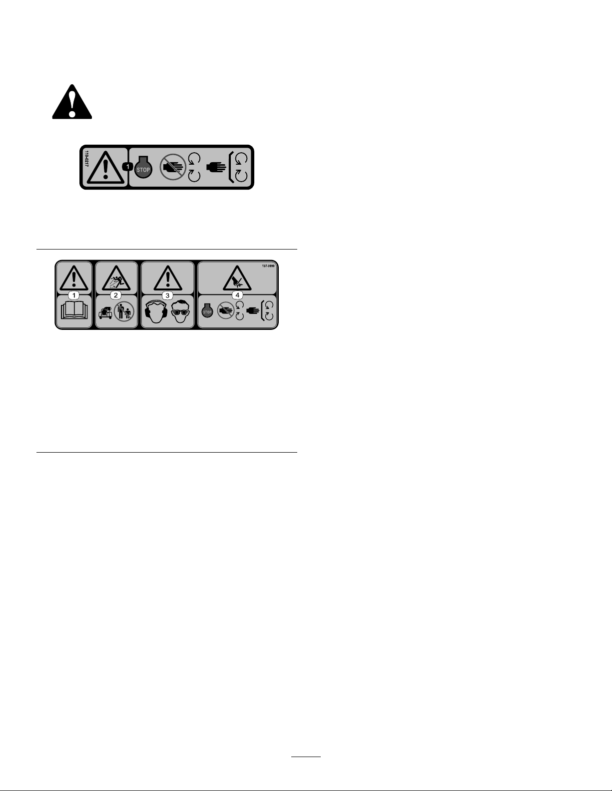
119-0217
1.Warning—shutofftheengine;stayawayfrommovingparts;
keepallguardsandshieldsinplace.
decal119-0217
1.Warning—readthe
Operator’sManual.
2.Thrownobject
hazard—keepbystanders
awayfromthemachine.
decal137-3999
137-3999
3.Warning—wearhearing
andeyeprotection.
4.Cutting/dismemberment
hazardofhands—shut
offtheengine;keep
handsawayfrommoving
parts;keepallguardsand
shieldsinplace.
4
Page 5
Setup
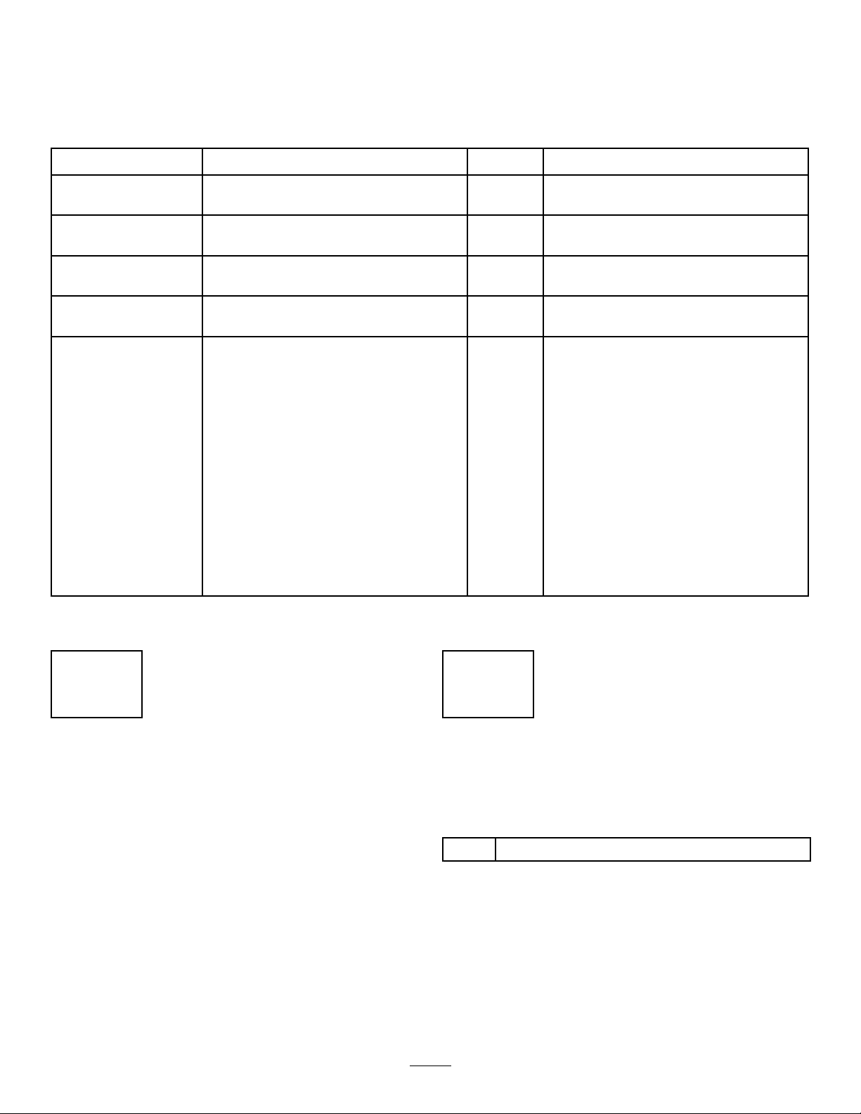
LooseParts
Usethechartbelowtoverifythatallpartshavebeenshipped.
ProcedureDescription
1
2
3
4
5
Nopartsrequired
WheelWeightKit(soldseparately)
Nopartsrequired
Nopartsrequired
Blowerassembly1
Bushingassembly2
Carriagebolt(3/8x2-1/4inches)
Locknut(3/8inch)
Receiverhitch1
Heatshield1
Bumper2
Thread-formingscrew(1/4x1/2inch)
Stopbracket
Carriagebolt(3/8x1inch)
Nut(3/8inch)
Washer1
Spacer
Thread-formingscrew(1/4x1-1/4inch)
Qty.
Use
–
1
–
–
2
2
2
1
1
1
1
1
Preparethemachine.
InstalltheWheelWeightKit(optional).
Positionthecasterwheels.
Removethefanguard.
Installtheblower.
Important:InstalltheLowFlowHydraulicsKitonyourmachinebeforeinstallingthiskit.
1
PreparingtheMachine
2
InstallingtheWheelWeight Kit(Optional)
NoPartsRequired
Partsneededforthisprocedure:
Procedure
1.Parkthemachineonalevelsurface.
2.LowertheA-frame.
3.DisengagethePTO,engagetheparkingbrake,
andmovethemotion-controlleversoutwardto
theNEUTRAL-LOCKposition.
4.Shutofftheengineandremovethekey.
1
WheelWeightKit(soldseparately)
Procedure
Installingwheelweightscanimprovetractionon
themachinewhenusingtheblower;refertothe
InstallationInstructionsfortheWheelWeightKit.
5
Page 6
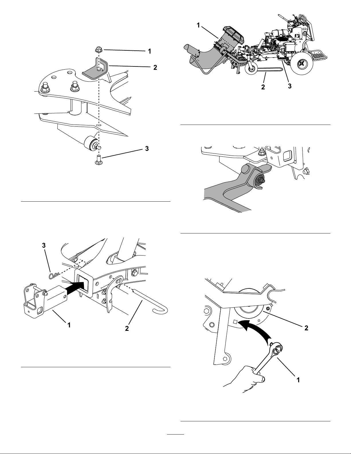
3
4
PositioningtheCaster
Wheels
NoPartsRequired
Procedure
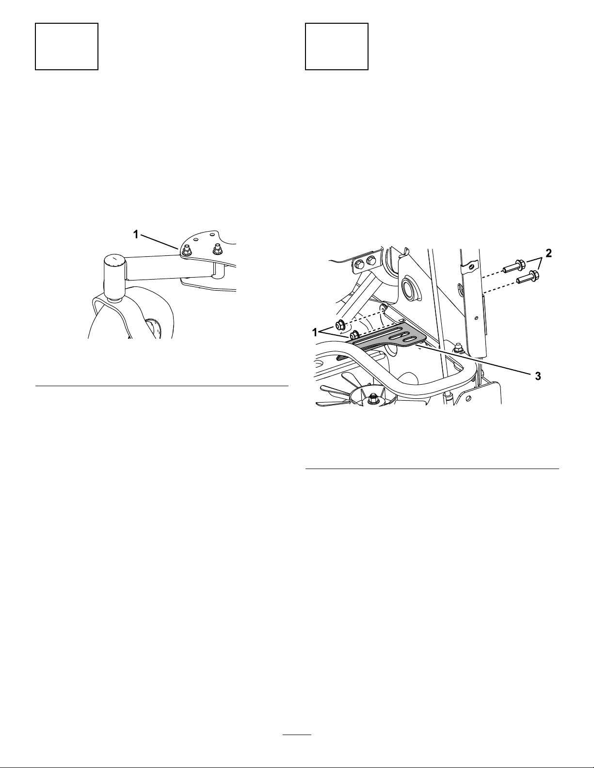
Forbothcasters,removethenutandbolt,movethe
castertothefrontposition,andinstallthenutandbolt
(Figure3).Torqueto91to113N∙m(67to83ft-lb).
Figure3
RemovingtheRightFan Guard
NoPartsRequired
Procedure
1.Removethefueltank;refertotheOperator’s
Manualforthemachine.
2.Removeandretainthe2bolts,2nuts,andthe
rightfanguard(Figure4).
g230693
1.Nutandbolt
g246823
Figure4
1.Nut(3/8inch)3.Rightfanguard
2.Bolt(3/8x1-1/4inch)
3.Installtheboltsandnutsyouremovedand
torqueto41to49N∙m(30to36ft-lb).
4.Installthefueltank.
6
Page 7

5
InstallingtheBlower
Partsneededforthisprocedure:
1Blowerassembly
2Bushingassembly
2
Carriagebolt(3/8x2-1/4inches)
2
Locknut(3/8inch)
1Receiverhitch
1Heatshield
2Bumper
2
Thread-formingscrew(1/4x1/2inch)
1
Stopbracket
1
Carriagebolt(3/8x1inch)
1
Nut(3/8inch)
1Washer
1
Spacer
1
Thread-formingscrew(1/4x1-1/4inch)
g246215
Figure6
1.Carriagebolt3.Muferguard
2.Nut
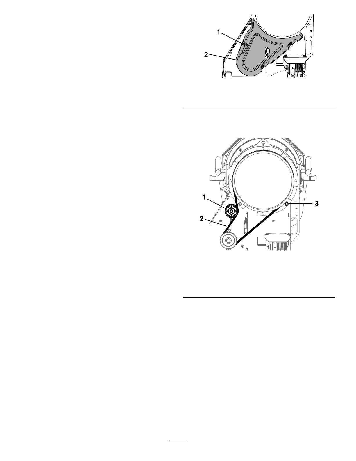
4.Looselyinstalltheheatshieldoverthemufer
guard,withthetabsinsidethemuferguardand
totheinsideoftheconsoletower,usingthe2
thread-formingbolts(1/4x1/2inch)andthe
carriageboltandnutyouremovedpreviously
(Figure7).
Important:Tominimizedebrisbuildupon
themufer,installtheheatshieldonthe
machinewhenusingtheblower.
Procedure
1.Removetheair-cleanercoverandlter;referto
theOperator’sManualforthemachine.
2.Installthe2bumpersontheheatshield(Figure
5).
Figure5
1.Heatshield2.Bumper
g256853
Figure7
1.Carriagebolt
g256852
2.Nut
3.Drillhere.
4.Heatshield
5.Thread-formingbolt—1/4
x1/2inch(2)
6.Tab(insidemuferguard)
3.Removethetopcarriageboltandnutsecuring
themuferguardtothemachine(Figure6).
7
Page 8

5.Usingthecenterholeintheheatshieldasa
template,drillahole(7/32inch)intothemufer
guard(Figure7).
6.Usethethread-formingbolt(1/4x1-1/4inch)
andwashertoinstallthespacerbetweenthe
heatshieldandmuferguard(Figure8).
Figure8
9.Useacarriagebolt(3/8x2-1/4inches)andnut
(3/8inch)toinstallthebushingassembliesto
themachine(Figure9).T orquetheboltto37to
45N∙m(27to33ft-lb).
Note:Therubberangeofthebushingshould
facetowardtheinsideofthemachineasshown
inFigure9.
g256854
1.Thread-formingbolt(1/4x
1-1/4)
2.Washer
3.Spacer
7.Torquethe3thread-formingboltsto4.5N∙m
(40in-lb).
Note:Donottorquethecarriageboltatthis
time.
8.Installtheair-cleanerlterandcover.
1.Carriagebolt(3/8x2-1/4
inches)
2.Bushingassembly
g250302
Figure9
3.Nut(3/8inch)
4.Rubberange
8
Page 9
10.Useacarriagebolt(3/8x1inch)andalocknut
(3/8inch)toinstallthestopbrackettotheright
sideofthemachine(Figure10).T orquethebolt
to37to45N∙m(27to33ft-lb).
g230767
Figure12
Figure10
1.Locknut(3/8inch)3.Carriagebolt(3/8x1inch)
2.Stopbracket
11.Removethehitchpinandcotterpinfromthe
A-frameanduseittoinstallthehitchreceiver
(Figure11).Ensurethatthepinlocksthe
A-frametothecrosstube.
1.Blowerassembly
2.Belt
3.Clutch
13.Placetheblowerassemblyforksontothe
bushingassemblies(Figure13).
g250341
g250511
Figure13
14.Installthebeltontotheclutch.Verifythatthe
beltisstillroutedontheblowerpulleysandis
seatedproperlyinthepulleygrooves.
Note:Y oucanuseadriveratchet(1/2inch)to
movetheleftidlerpulley(Figure14).
Figure11
1.Hitchreceiver
2.Hitchpin
3.Cotterpin
12.Movetheblowerinfrontofthemachineandlay
thebeltunderneaththemachinesothatitis
linedupwiththeclutch(Figure12).
g230752
g231579
Figure14
1.Driveratchet2.Pulley
9
Page 10

15.RaisetheblowerasdescribedinRaisingthe
Blower(page12).
16.Connectthehydraulichosestothe
quick-disconnectcouplingsontheLowFlow
HydraulicsKit.
WARNING
Hydraulicuidescapingunderpressure
canpenetrateskinandcauseinjury.
Fluidinjectedintotheskinmustbe
surgicallyremovedwithinafewhoursby
adoctorfamiliarwiththisformofinjury;
otherwise,gangrenemayresult.
•Ensurethatallhydraulic-uidhoses
andlinesareingoodconditionandall
hydraulicconnectionsandttingsare
tightbeforeapplyingpressuretothe
hydraulicsystem.
•Keepyourbodyandhandsawayfrom
pinholeleaksornozzlesthateject
high-pressurehydraulicuid.
•Usecardboardorpapertond
hydraulicleaks;neveruseyour
hands.
Operation
OperationSafety
•Themachineexceedsnoiselevelsof85dB(A)at
theoperator’sposition.Usehearingprotection
forprolongedexposuretoreducethepotentialof
permanenthearingdamage.
•Wearappropriateclothingincludingeyeprotection;
longpants;substantial,slip-resistantfootwear;
andhearingprotection.Tiebacklonghairanddo
notwearlooseclothingorloosejewelry.
•Stayawayfromthenozzleopeningwhenthe
machineisoperating.Keepallbystandersaway
fromthenozzleopeninganddon’tdirectdischarge
towardbystanders.
•Whenapersonorpetappearsunexpectedlyinor
neartheoperatingarea,stopoperation.Careless
operation,combinedwithterrainangles,ricochets,
orimproperlypositionedguardscanleadtothrown
objectinjuries.Donotresumeoperationuntilthe
areaisclearedofpeopleandpets.
•Shutofftheengine,removethekey,waitforall
movementtostop,andallowthemachinetocool
beforeadjusting,cleaning,storing,orrepairingit.
OperatingtheBlower
Important:Donotoperatetheblowerwithoutthe
heatshieldinstalledonthemachine.
Tooperatetheblower,starttheengine,movethe
motion-controlleverstothecenter,unlockedposition,
movethethrottleleverbetweenhalfandfullthrottle,
andengagethePTO(Figure15).
Figure15
Usetherightswitchforthelowowkittorotatethe
nozzletothedesireddirection(Figure16),anduse
thethrottlelevertoadjusttheblowerspeed.
g009174
Note:Ifyouwouldliketochangethedirectionthe
nozzlerotateswhenyoumovetheswitchaparticular
direction,removethequick-disconnectcouplingsfrom
theLow-FlowHydraulicsKithosesandinstallthemon
theoppositehoses.
10
Page 11

Figure16
1.Notusedwiththiskit2.Rotatetheblowernozzle.
Ensuretocleandebrisfromthemachineregularly.
WARNING
Dischargedairhasconsiderableforceand
couldcauseinjuryorlossoffooting.
•Stayawayfromthenozzleopeningwhen
themachineisoperating.
•Keepbystandersawayfromthenozzle
openingwhenthemachineisoperating.
UsingtheKickstand
LoweringtheBlower
1.Rotatetheblowernozzlesothatitpoints
upward.
g037041
g230843
Figure17
1.Kickstandlockingpinin
theengagedposition
2.Kickstandlockingpinin
thedisengagedposition
3.Kickstandintheblower
operatingposition
4.Kickstandintheblower
storageposition
5.Removethehitchpinandhairpincottersecuring
theblowerassemblytothehitchreceiver(Figure
18).
2.Parkthemachineonalevelsurface,disengage
thePTO,movethemotion-controlleverstothe
NEUTRAL-LOCKposition,andengagetheparking
brake.
3.Shutofftheengine,removethekey ,andwait
forallmovingpartstostopbeforeleavingthe
operatingposition.
4.Pulloutthekickstandlockingpinsonbothsides
ofthemachine,rotatethem90degreessothat
theyaredisengaged,androtatethekickstand
awayfromthemachine(Figure17).Engagethe
pinsandensurethattheysnapintoposition.
g230859
Figure18
1.Hairpincotter2.Hitchpin
11
Page 12

6.Holdthekickstandandpushthereleaselever
down.Slowlylowerthekickstandtotheground.
Note:Oncetheleverdisengagesthehitchpin,
theblowerrotatesdown.
g230770
Figure21
1.Hairpincotter2.Hitchpin
Figure19
1.Releaselever
RaisingtheBlower
1.Raisetheblowersothatitlatchesonthehitch
receiver(Figure20andFigure21).
g230858
2.Securetheassemblytothehitchreceiverusing
thehitchpinandhairpincotterattachedtothe
receiver(Figure21).
3.Pulloutthekickstandlockingpinsonbothsides
ofthemachine,rotatethem90degreessothat
theyaredisengaged,andraisethekickstand
(Figure22).Engagetheknobsandensurethat
thepinssnapintoposition.
Figure20
g230769
g230843
Figure22
1.Kickstandlockingpinin
theengagedposition
2.Kickstandlockingpinin
thedisengagedposition
3.Kickstandintheblower
operatingposition
4.Kickstandintheblower
storageposition
12
Page 13

RemovingtheBlower
1.Parkthemachineonalevelsurface,disengage
thePTO,engagetheparkingbrake,and
movethemotion-controlleversoutwardtothe
NEUTRAL-LOCKposition.
2.Shutofftheengineandremovethekey.
3.Disconnecttheblowerhydraulichosesfromthe
quick-disconnectcouplingsontheLowFlowKit.
4.Lowertheblower;refertoLoweringtheBlower
(page11).
5.Removethebeltfromtheclutch.
Note:Ifneeded,useadriveratchet(1/2inch)
tomovetheleftidlerpulley(Figure23).
7.Removethehitchpin,cotterpin,andhitch
receiverfromtheA-frame.Installthehitchpin
andcotterpintosecuretheA-frame(Figure24).
g246845
Figure24
Figure23
1.Driveratchet2.Pulley
6.Lifttheblowerassemblyoffthebushing
assembliesonthemachine.
1.Hitchreceiver
2.Hitchpin
3.Cotterpin
8.Removethestopbrackets(Figure25).
g231579
g250341
Figure25
1.Locknut(3/8inch)3.Carriagebolt(3/8x1inch)
2.Stopbracket
9.Removebothbushingassemblies(Figure26).
13
Page 14

Figure26
11.Removethespacer
g230751
1.Bolt3.Nut
2.Bushingassembly
10.Usethefastenerstostorethebushing
assembliesontheleftsideoftheblowerframe
(Figure27).
Figure27
g256854
Figure28
1.Thread-formingbolt(1/4x
1-1/4)
2.Washer
3.Spacer
12.Removetheheatshield(Figure29).
Important:Wheneveryouinstalltheblower
onanothermachine,alsoinstalltheheat
shield.
g246867
1.Bolt3.Nut
2.Bushingassembly
Figure29
1.Carriagebolt
2.Nut
3.Heatshield
4.Thread-formingbolt(2)
13.Installthecarriageboltandnuttosecurethe
muferguard.T orquetheboltto1978to2542
N∙cm(175to225in-lb).
14.Removethefueltank;refertotheOperator’s
Manualforthemachine.
14
g256855
Page 15

15.Removethe2boltsand2nutsfromtheright
sideofthemachineandusethemtoinstallfan
guard(Figure30).T orquetheboltsto37to45
N∙m(27to33ft-lb).
Figure30
OperatingTips
•Practiceoperatingtheblower.Blowthesame
directionthewindisblowingtopreventmaterial
fromblowingbackintotheclearedarea.
•Beawareoftheblowernozzledirectionanddonot
pointitatanyone.
•Adjustthenozzleopeningsothatitblowsunder
thedebris.
•Usecautionwhenblowingaroundnewlyplanted
sodastheforceoftheaircoulddisruptthegrass.
•Thenozzleoutletpositionaffectsthedistance
debriscanbeblown.
•Whenyourotatethenozzle,rotateitupwardand
aroundtopreventblowingdebrisbackintothe
clearedarea.
g246823
1.Nut(3/8inch)
2.Bolt(3/8x1-1/4inches)
16.Installthefueltank.
3.Fanguard
15
Page 16
Maintenance
MaintenanceSafety
•Parkthemachineonalevelsurface.Neverallow
untrainedpersonneltoservicethemachine.
•Usejackstandstosupportthemachinewhen
required.
•Removethekeyfromtheswitchonthetraction
unittopreventaccidentalstartingoftheengine
whenservicing,adjusting,orstoringthemachine.
1.Bolt(3)
g246599
Figure31
2.Beltcover
•Performonlythosemaintenanceinstructions
describedinthismanual.Iftheblowerrequiresa
majorrepair,contactanauthorizedT orodistributor.
•Ensurethatthemachineisinsafeoperating
conditionbykeepingnuts,bolts,andscrewstight.
•Keepyourhandsandfeetawayfrommovingparts.
Donotmakeadjustmentswiththeenginerunning.
•Keepallpartsingoodworkingconditionandall
hardwaretightened.Replaceallwornordamaged
decals.
•Toensureoptimumperformanceandcontinued
safetycerticationofthemachine,useonly
genuineT ororeplacementpartsandaccessories.
Replacementpartsandaccessoriesmadeby
othermanufacturerscouldbedangerous,and
suchusecouldvoidtheproductwarranty.
CheckingtheBelts
ServiceInterval:Every300hours
Checkthebeltsforcracks,frayededges,burnmarks,
oranyotherdamage.Replacedamagedbelts.
4.Loosenthenutonthetoppulleyandslidethe
pulleyuptoreleasetensiononthebelt(Figure
32).
g250730
Figure32
Blowernozzlenotshownforclarity
1.Toppulley3.Rollerbearing
2.Belt
ReplacingtheBlowerBelt
1.Parkthemachineonalevelsurface,disengage
thePTO,andengagetheparkingbrake.
2.Shutofftheengine,removethekey ,andwait
forallmovingpartstostopbeforeleavingthe
operatingposition.
3.Removethebeltcover(Figure31).
5.Removetherollerbearing(Figure32).
6.Removethebeltandinstallanewbelt(Figure
32).
7.Installtherollerbearing(Figure32)
8.Slidethetoppulleydownuntilthebeltdeection
is5mm(0.19inch)atthecenterofthelargest
spanandtightenthenut(Figure32).
16
Page 17
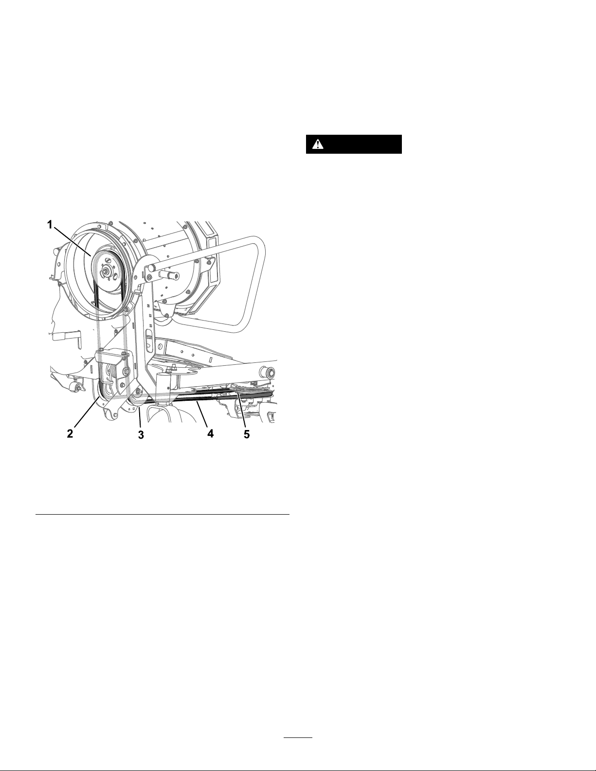
ReplacingtheClutchBelt
CheckingtheHydraulic
1.Parkthemachineonalevelsurface,disengage
thePTO,andengagetheparkingbrake.
2.Shutofftheengine,removethekey ,andwait
forallmovingpartstostopbeforeleavingthe
operatingposition.
3.Lowertheblower.
4.Loosenthenozzleclampandremovethenozzle.
5.Removethebeltfromthemachineclutch.
Note:Y oucanuseadriveratchet(1/2inch)to
movetheleftidlerpulley(Figure14).
6.Removethebeltfromthefanpulley(Figure33).
Hoses
ServiceInterval:Every100hours
Checkthehydraulichosesforleaks,loosettings,
kinkedlines,loosemountingsupports,wear,weather,
andchemicaldeterioration.
WARNING
Hydraulicuidescapingunderpressurecan
penetrateskinandcauseinjury.Fluidinjected
intotheskinmustbesurgicallyremoved
withinafewhoursbyadoctorfamiliarwith
thisformofinjury;otherwise,gangrenemay
result.
•Ensurethatallhydraulic-uidhoses
andlinesareingoodconditionandall
hydraulicconnectionsandttingsaretight
beforeapplyingpressuretothehydraulic
system.
•Keepyourbodyandhandsawayfrom
pinholeleaksornozzlesthateject
high-pressurehydraulicuid.
Figure33
1.Fanpulley4.Belt
2.Rightidlerpulley
3.Leftidlerpulley
7.Routethebeltdownthroughthedriveadapter
assembly,aroundtheidlerpulleys,andaround
theclutchpulley(Figure33).Ensurethatthe
beltisseatedproperlyinthepulleygrooves.
5.Clutchpulley
Note:Ifneeded,youmayuseadriveratchet
(1/2inch)tomovetheleftidlerpulley(Figure14).
•Usecardboardorpapertondhydraulic
leaks;neveruseyourhands.
RemovingDebrisfromthe Machine
g246640
ServiceInterval:Aftereachuse
1.Parkthemachineonalevelsurface,disengage
thePTO,andengagetheparkingbrake.
2.Shutofftheengine,removethekey ,andwait
forallmovingpartstostopbeforeleavingthe
operatingposition.
3.Cleandebrisfromthedrives,mufer,andengine
aftereachuse.
17
Page 18

Notes:
Page 19

Notes:
Page 20

 Loading...