

Page 1

ISOMountSeatKit
ZMaster
ModelNo.78581
®
RidingMower
Installation
LooseParts
Usethechartbelowtoverifythatallpartshavebeenshipped.
FormNo.3376-913RevA
InstallationInstructions
ProcedureDescription
1
2
3
Nopartsrequired
Nut(3/8-16)
Nut(5/16-18)
SeatIsolator
Bolt(5/16x3/4)
Washer4
Plasticcabletie1
TiltFrameAssembly1
Nopartsrequired
1
RemovingtheSeat
NoPartsRequired
1.Ensurethatallmovingpartshavestopped.Setthe
parkingbrakeandremovethekey .
Qty.
12
Use
–
4
4
8
–
Removetheseat.
Installtheseat.
Testthesafetyinterlocksystem.
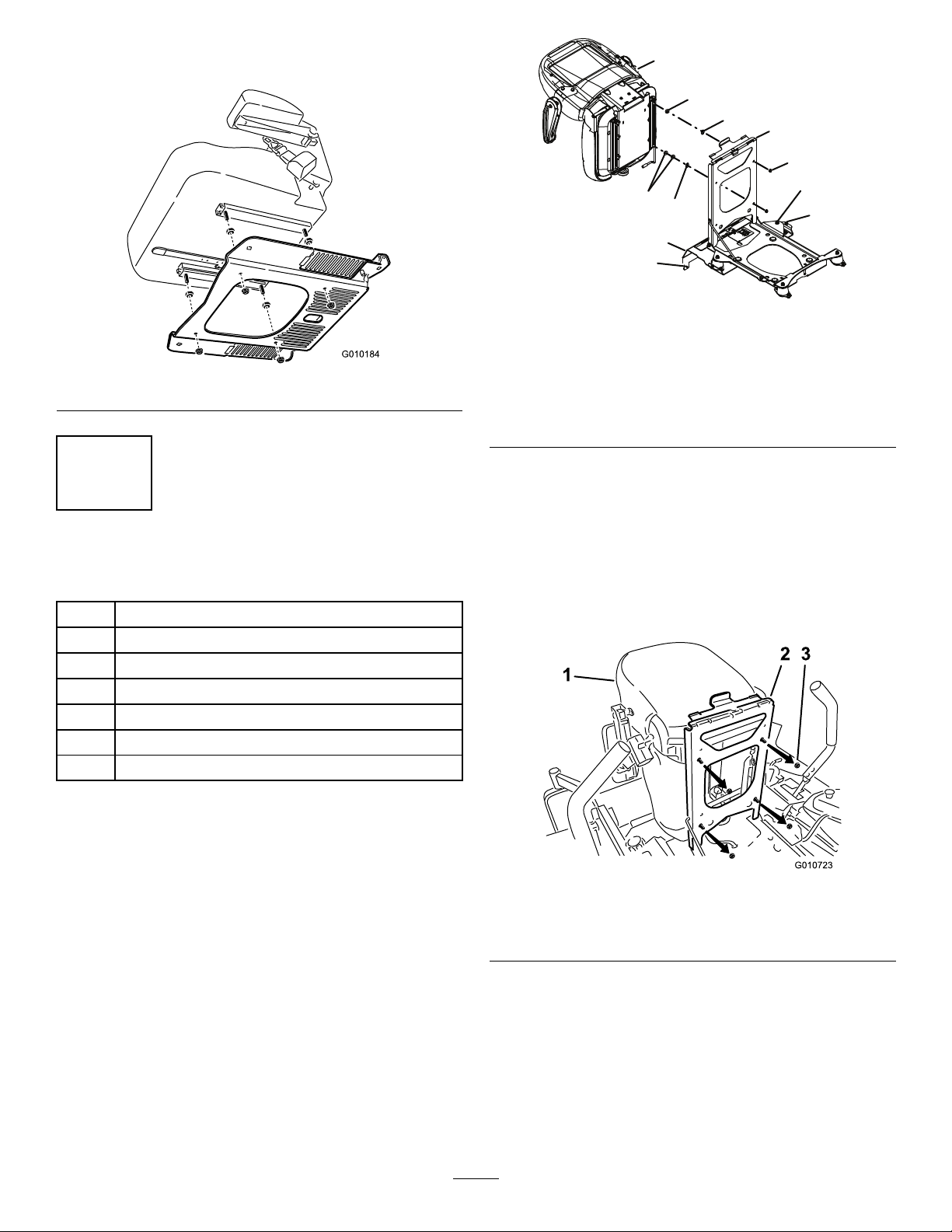
Figure1
2.Slidetheseatallthewayforwardanddisconnectthe
seatwireharnessfromthemainwireharness.
3.Removetheplastictieholdingtheseatwireharness
totheseatmountframe.
4.Removetherearhardware,loosentheframebolts,and
slidetheseatframeforwardintheslots(Figure1).
©2013—TheToro®Company
8111LyndaleAvenueSouth
Bloomington,MN55420
Registeratwww.T oro.com.
1.Rearhardwarelocation3.Bolts,nuts,andslots
2.Seatframe
OriginalInstructions(EN)
PrintedintheUSA.
AllRightsReserved
*3376-913*A
Page 2
5.Removetheseatplatefromtheseatbyremovingthe
G015542
1
2
9
10
10
4
5
6
3
8
7
spacersandangenuts(Figure2).
Figure2
Figure3
1.Seat6.Coverboltandnuts
2.Spacer7.Coverscrews
3.Seatframe
4.Nut
5.Flangenuts10.Washers
3.Repeatontherearsideofthefueltankcover.
8.Fueltankcover
9.Spacers
2
InstallingtheISOMountframe
Partsneededforthisprocedure:
4
Nut(3/8-16)
12
Nut(5/16-18)
4
SeatIsolator
8
Bolt(5/16x3/4)
4Washer
1Plasticcabletie
1TiltFrameAssembly
1.Removeandretainthescrews,bolts,andnutsforthe
fueltakecover.
Note:Becarefulsoasnottodamagethewireharness.
2.Mountthe2isolatorstothefrontsideofthefueltank
coverwhereshowninFigure3using4ofthecarriage
boltsandnuts.
4.Installthefueltankcover.
5.Installthetiltframeassemblyontothe4isolatorsand
securethemwiththe4angednuts.
6.Torquethenutsto47.5N-m(35ft-lb).
7.Installthewashersontotheseatstudsandmountthe
seattothetiltframeassembly(
Figure4
1.Seat
2.Seatframe
Figure4).
3.Nut
8.Securetheseattothetiltframeassemblywiththenuts.
Torqueto30.5N-m(22.5ft-lbs).
9.Plugtheseatharnessconnectorintotheseatswitch
locatedundertheseat.
10.Slowlylowertheseatdownandensurethatthewire
harnessdoesnotgetpinched.
11.Movetheseattothefurthestrearposition.
2
Page 3

Note:Ensurethatthewireharnessdoesnotget
pinched.
Trystartingtheengine;theengineshouldnotcrank.
Repeatforothercontrollever.
12.Installtheplastictietopreventthewireharnessfrom
beingpinched.
3
TestingtheSafetyInterlock System
NoPartsRequired
Procedure
CAUTION
Ifsafetyinterlockswitchesaredisconnectedor
damagedthemachinecouldoperateunexpectedly
causingpersonalinjury.
•Donottamperwiththeinterlockswitches.
•Checktheoperationoftheinterlockswitches
dailyandreplaceanydamagedswitchesbefore
operatingthemachine.
3.Sittingontheseat,engagetheparkingbrake,movethe
bladecontrolswitch(PTO)tooffandmovethemotion
controlleverstoneutrallockposition.Nowstartthe
engine.Whiletheengineisrunning,releasetheparking
brake,engagethebladecontrolswitch(PTO)andrise
slightlyfromtheseat;theengineshouldstop.
4.Sittingontheseat,engagetheparkingbrake,movethe
bladecontrolswitch(PTO)tooffandmovethemotion
controlleverstoneutrallockposition.Nowstartthe
engine.Whiletheengineisrunning,centereither
motioncontrolandmove(forwardorreverse);the
engineshouldstop.Repeatforothermotioncontrol.
5.Sittingontheseat,disengagetheparkingbrake,move
thebladecontrolswitch(PTO)tooffandmovethe
motioncontrolleverstoneutrallockposition.Try
startingtheengine;theengineshouldnotcrank.
Thesafetyinterlocksystemisdesignedtopreventtheengine
fromstartingunless:
•Theparkingbrakeisengaged.
•Thebladecontrolswitch(PTO)isdisengaged.
•Themotioncontrolleversareintheneutrallocked
position
Thesafetyinterlocksystemalsoisdesignedtostopthe
enginewhenthetractioncontrolsaremovedfromthelocked
positionwiththeparkingbrakeengagedorifyourisefrom
theseatwhenthePTOisengaged.
Thehourmeterhassymbolstonotifytheuserwhenthe
interlockcomponentisinthecorrectposition.Whenthe
componentisinthecorrectposition,atrianglewilllightup
inthecorrespondingsquare.
Testthesafetyinterlocksystembeforeyouusethemachine
eachtime.Ifthesafetysystemdoesnotoperateasdescribed
below ,haveanAuthorizedServiceDealerrepairthesafety
systemimmediately.
1.Sittingontheseat,engagetheparkingbrakeandmove
thebladecontrolswitch(PTO)toon.Trystartingthe
engine;theengineshouldnotcrank.
2.Sittingontheseat,engagetheparkingbrakeandmove
thebladecontrolswitch(PTO)tooff.Moveeither
motioncontrollever(outofneutrallockedposition).
3
Page 4

 Loading...