

Page 1
FormNo.3415-397RevC
E-ZVac
2016andAfterGrandstand
ModelNo.78570—SerialNo.400000000andUp
™
TwinBagger
®
Mower
Registeratwww.T oro.com.
OriginalInstructions(EN)
Note:
Thiskitrequiresthesimultaneousinstallationofotherkitsto
functionproperly.ContactyourAuthorizedServiceDealer
toobtainthecorrespondingnecessaryparts.Formore
information,visitusatwww.Toro.com.
*3415-397*C
Page 2
ThisproductcomplieswithallrelevantEuropean
directives.Fordetails,pleaseseetheDeclarationof
Incorporation(DOI)atthebackofthispublication.
WARNING
CALIFORNIA
Proposition65Warning
Thisproductcontainsachemical
orchemicalsknowntotheStateof
Californiatocausecancer,birthdefects,
orreproductiveharm.
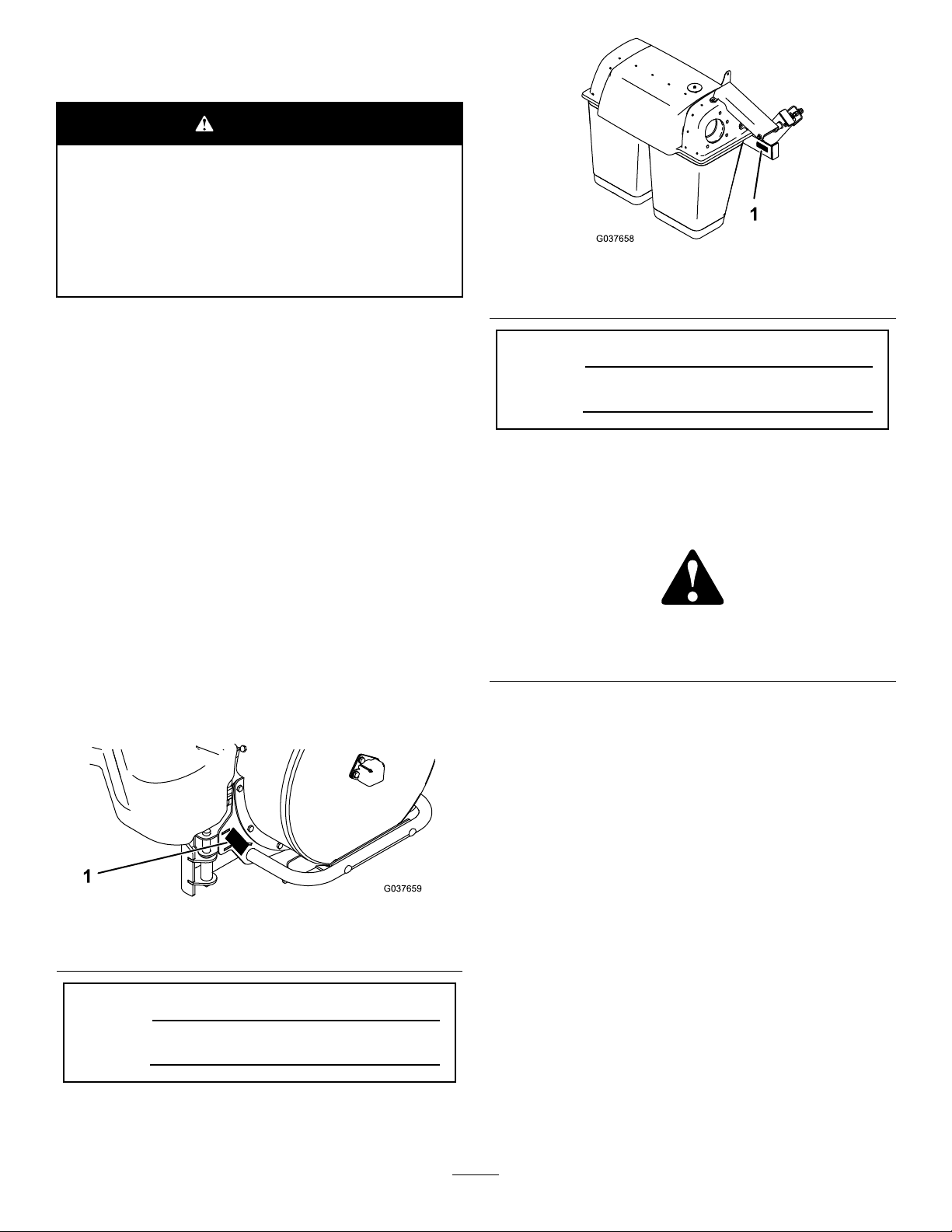
g037658
Figure2
1.Baggermodelandserialnumberlocation
ModelNo.
Introduction
Readthisinformationcarefullytolearnhowtooperate
andmaintainyourproductproperlyandtoavoid
injuryandproductdamage.Youareresponsiblefor
operatingtheproductproperlyandsafely.
YoumaycontactT orodirectlyatwww.T oro.com
forproductsafetyandoperationtrainingmaterials,
accessoryinformation,helpndingadealer,orto
registeryourproduct.
Wheneveryouneedservice,genuineToroparts,or
additionalinformation,contactanAuthorizedService
DealerorToroCustomerServiceandhavethemodel
andserialnumbersofyourproductready.Figure1
identiesthelocationofthemodelandserialnumbers
ontheproduct.Writethenumbersinthespace
provided.
SerialNo.
Thismanualidentiespotentialhazardsandhas
safetymessagesidentiedbythesafety-alertsymbol
(Figure3),whichsignalsahazardthatmaycause
seriousinjuryordeathifyoudonotfollowthe
recommendedprecautions.
g000502
Figure3
1.Safety-alertsymbol
Thismanualuses2wordstohighlightinformation.
Importantcallsattentiontospecialmechanical
informationandNoteemphasizesgeneralinformation
worthyofspecialattention.
Contents
Figure1
1.Blowermodelandserialnumberlocation
ModelNo.
SerialNo.
©2017—TheToro®Company
8111LyndaleAvenueSouth
Bloomington,MN55420
Safety.......................................................................3
g037659
SafetyandInstructionalDecals..........................5
Setup........................................................................6
1PreparingtheMachine.....................................7
2InstallingtheE-ZVacBlowerandDrive
Kit....................................................................7
3InstallingtheBlowerAssembly ,Belt,and
BeltCover.......................................................7
4InstallingtheBrackets......................................8
5InstallingtheBaggerFrame............................11
6InstallingtheBags.........................................12
7InstallingtheBaggerTube.............................12
8InstallingtheWeight.......................................14
Operation................................................................14
OperationSafety..............................................14
Contactusatwww.Toro.com.
2
PrintedintheUSA
AllRightsReserved
Page 3

PositioningtheFlowBafe................................15
UsingtheFillIndicator......................................15
EmptyingtheGrassBags.................................15
ClearingObstructionsfromtheBagger
System..........................................................16
RemovingtheBagger.......................................16
TransportingtheMachine.................................17
OperatingTips.................................................17
Maintenance...........................................................19
RecommendedMaintenanceSchedule(s)...........19
CleaningtheBaggerandBags.........................19
InspectingtheBaggerBelt................................19
ReplacingtheBaggerBelt................................19
InspectingtheBagger.......................................20
InspectingtheMowerBlades............................20
InstallingtheMowerBlades..............................20
Storage...................................................................21
Troubleshooting......................................................22
Safety
WARNING
Toavoidpersonalinjury,followthese
procedures:
•Becomefamiliarwithalloperatingand
safetyinstructionsintheOperator's
Manualforthemowerbeforeusingthis
attachment.
•Neverremovethedischargetube,bags,
baggerhood,orthechutewhiletheengine
isrunning.
•Alwaysshutofftheengineandwaitforall
movingpartstostopbeforeclearingan
obstructionfromthebaggingsystem.
•Neverdomaintenanceorrepairswhilethe
engineisrunning.
WARNING
Whenthebaggerisinoperation,theblower
isrotatingandcancutofforinjurehandsand
ngers.
•Beforeadjusting,cleaning,repairing
andinspectingtheblower,andbefore
uncloggingthechute,shutofftheengine
andwaitforallmovingpartstostop.
Removethekey.
•Useastickorsimilarobject,notyour
hands,toremoveanobstructionfromthe
blowerandtube.
•Keepyourface,hands,feet,andanyother
partofyourbodyorclothingawayfrom
concealed,moving,orrotatingparts.
WARNING
Debris,suchasleaves,grass,orbrushcan
catchre.Areintheengineareacancause
personalinjuryandpropertydamage.
•Keeptheengineandmuferareafreeof
debrisaccumulation.
•Takecarewhenopeningthebaggercover
tokeepdebrisfromfallingontotheengine
andmuferarea.
•Allowthemachinetocoolbeforestoringit.
Thefollowinglistcontainssafetyinformationspecic
toT oroproductsandothersafetyinformationyou
mustknow.
3
Page 4

•Becomefamiliarwiththesafeoperationofthe
equipment,withtheoperatorcontrols,andsafety
signs.
•Useextracarewithgrasscatchersorother
attachments.Thesecanchangetheoperating
characteristicsandthestabilityofthemachine.
•Followtherecommendationsforaddingor
removingweightsasdescribedintheOperator’s
Manualforthemachine.
•Donotuseagrasscatcheronsteepslopes.A
heavygrasscatchercouldcauselossofcontrol
oroverturnthemachine.
•Slowdownanduseextracareonhillsides.Mow
slopessidetoside.Turfconditionscanaffectthe
stabilityofthemachine.Useextremecaution
whileoperatingneardrop-offs.
•Keepallmovementonslopesslowandgradual.
Donotmakesuddenchangesinspeed,directions,
orturning.
•Thegrasscatchercanobstructtheviewtothe
rear.Useextracarewhenoperatingthemachine
inreverse.
•Usecarewhenloadingorunloadingthemachine
intoatrailerortruck.
•Neveroperatewiththedischargedeectorraised,
removed,oraltered,unlessyouareusingagrass
catcher.
•Keepyourhandsandfeetawayfrommovingparts.
Donotmakeadjustmentswiththeenginerunning.
•Stopthemachineonlevelground,disengagethe
drives,settheparkingbrake,andshutoffthe
enginebeforeleavingtheoperator'spositionfor
anyreasonincludingemptyingthegrasscatcher
oruncloggingthechute.
•Donotoperatethemachinewithouteitherthe
entiregrasscatcher,thegrassdeector,and/or
guardinplace.
•Shutofftheenginebeforeremovingthegrass
catcheroruncloggingthechute.
•Donotleavegrassinthegrasscatcherfor
extendedperiodsoftime.
•Grasscatchercomponentsaresubjecttowear,
damage,anddeterioration,whichcouldexpose
youtomovingpartsorthrownobjects.Frequently
checkcomponentsandreplacethemwith
themanufacturer'srecommendedpartswhen
necessary.
4
Page 5
SafetyandInstructionalDecals
LB
KG
LB
KG
136-4053
LB
KG
LB
KG
Safetydecalsandinstructionsareeasilyvisibletotheoperatorandarelocatednearanyarea
ofpotentialdanger.Replaceanydecalthatisdamagedormissing.
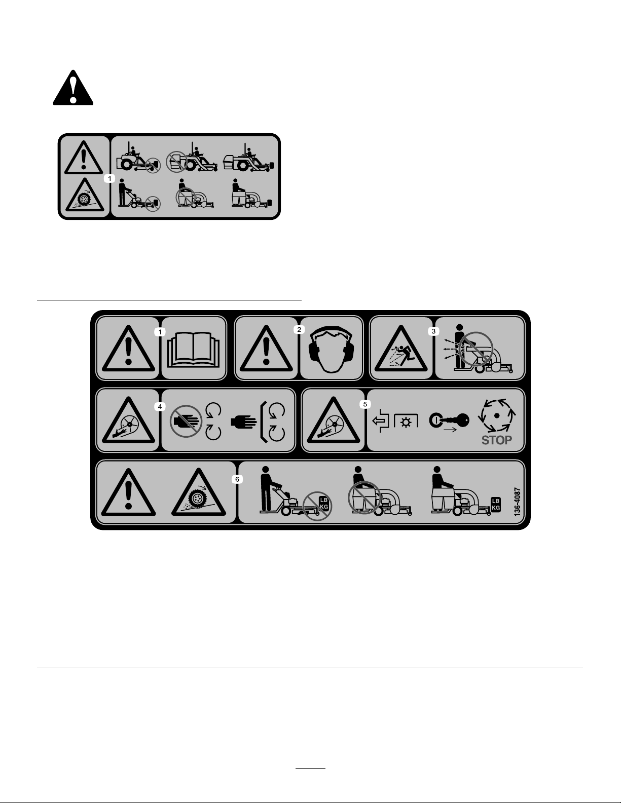
136-4053
1.Warning;lossoftraction—donotoperateonlywith
counterbalanceweightsinstalled;donotoperateonlywith
theE-ZVacinstalled;operateonlywithboththeE-ZVac
andcounterbalanceweightsinstalled.
decal136-4053
136-4087
1.Warning—readtheOperator’sManual.4.Cutting/dismembermenthazard,impeller—keepawayfrom
2.Warning—wearhearingprotection.
3.Thrownobjecthazard—donotruntheblowerwithoutthe
entirecollectionsysteminstalledandlatched.
movingparts;keepallguardsandcoversinplace.
5.Cutting/dismembermenthazard,impeller—disengagethe
PTO,removetheignitionkey ,andwaitforallmovingparts
tostop.
6.Warning;lossoftraction—donotoperateonlywith
counterbalanceweightsinstalled;donotoperateonlywith
E-ZVacinstalled;operateonlywithboththeE-ZVacand
counterbalanceweightsinstalled.
5
decal136-4087
Page 6

Setup
LooseParts
Usethechartbelowtoverifythatallpartshavebeenshipped.
ProcedureDescription
1
2
3
4
5
Nopartsrequired
E-ZVacBlowerandDriveKit(sold
separately)
Blowerassembly(fromtheBlowerand
DriveKit)
Belt(fromtheBlowerandDriveKit)
Beltcover(fromtheBlowerandDrive
Kit)
Knob(fromtheBlowerandDriveKit)
Frontmountbracket1
Lowermountbracket1
Rearmountbracket1
Rightmountbracket1
Flatwasher2
Bolt(3/8x4inches)
Carriagebolt(3/8x1inch)
Nut(3/8inch)
Carriagebolt(1/4x5/8inch)
Nut(1/4inch)
Bagger-frameassembly
Clevispin
Hairpincotter3
Thrustwasher1
Nut(3/8inch)
Carriagebolt(3/8x1inch)
Qty.
Use
–
1
1
1
1
1
2
1
1
2
2
1
2
1
1
Preparethemachine.
InstalltheE-ZVacBlowerandDriveKit
(soldseparately).
Installtheblowerassembly ,belt,and
beltcover.
Installthebrackets.
Installthebaggerframe.
6
7
8
Bag2Installthebags.
Tube1
Hoseclamp1
Blowerclamp2
Weight1
U-bolt1
LongU-bolt(forMultiForceTM
machineswith52-inchdecksonly)
Locknut(1/2inch)
1
2
Note:Determinetheleftandrightsidesofthemachinefromthenormaloperatingposition.
6
Installthebaggertube.
Installtheweight.
Page 7
1
3
PreparingtheMachine
NoPartsRequired
Procedure
Note:RemovetheRollerStriperKit,ifinstalled,prior
toinstallingthisattachment.
1.DisengagethePTO,movethemotion-control
leverstotheNEUTRAL-LOCKposition,and
engagetheparkingbrake.
2.Shutofftheengine,removethekey,andwait
forallmovingpartstostopbeforeleavingthe
operatingposition.
3.Repairallbentordamagedareasofmower
deckandreplaceanymissingparts.
4.Cleanthemachineofanydebrisonthedeckor
rearpartofthemachinetoeaseinstallation.
InstallingtheBlower Assembly,Belt,andBelt Cover
Partsneededforthisprocedure:
1
Blowerassembly(fromtheBlowerandDriveKit)
1
Belt(fromtheBlowerandDriveKit)
1
Beltcover(fromtheBlowerandDriveKit)
1
Knob(fromtheBlowerandDriveKit)
Procedure
1.Lowerthemowerdecktothelowestsetting.
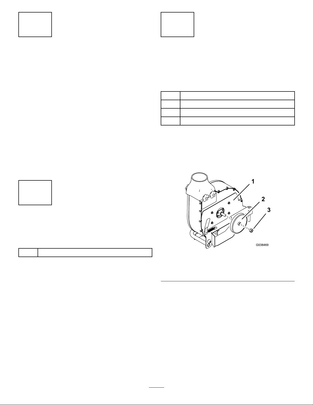
2.Removethepulleyfromtheblowerassembly
(Figure4).
2
InstallingtheE-ZVac BlowerandDriveKit
Partsneededforthisprocedure:
1
E-ZVacBlowerandDriveKit(soldseparately)
Procedure
RefertotheInstallationInstructionsforthekit.
g038469
Figure4
1.Blowerassembly3.Hexnut
2.Pulley
3.Insertthepinfromtheblowerassemblyintothe
blowermountbracketasshowninFigure5.
7
Page 8
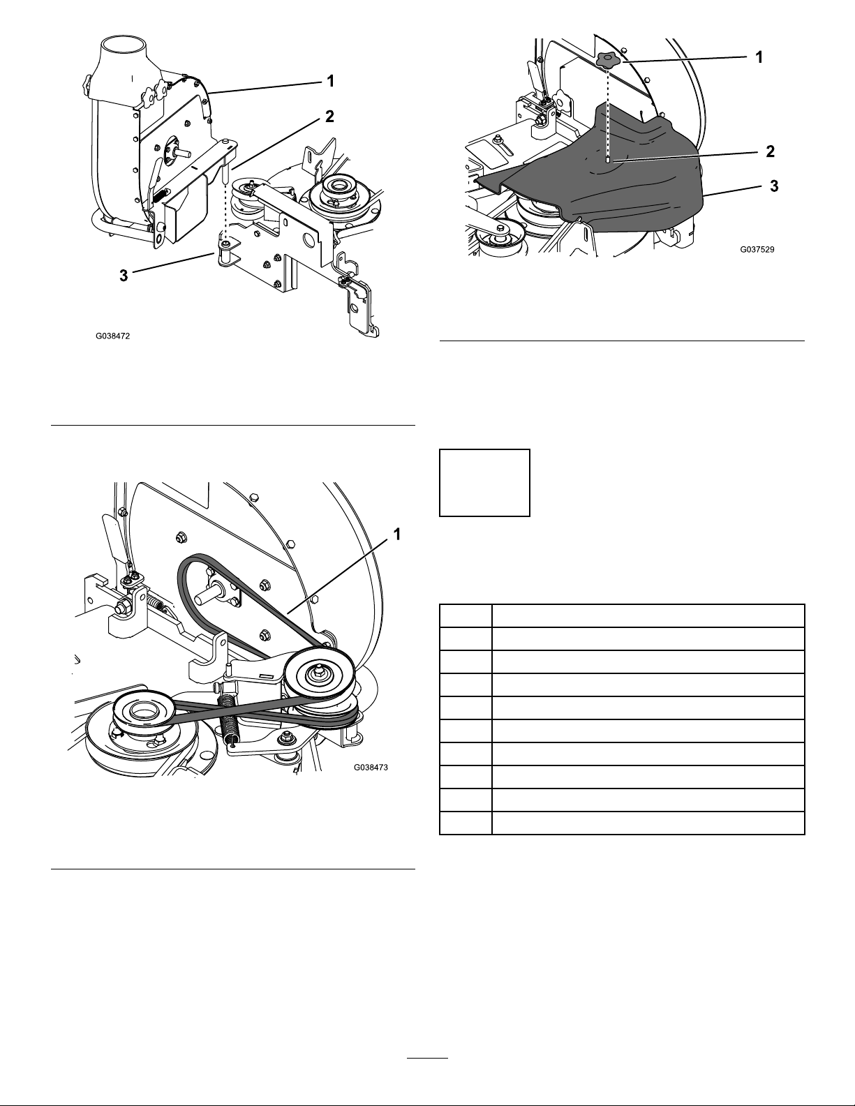
Figure5
1.Blowerassembly3.Insertthepinhere.
2.Pin
4.Installthebelttothepulleysandidlerassembly
asshowninFigure6.
Figure6
Beltguardandblowermountnotshown.
g037529
Figure7
1.Knob3.Beltcover
2.Idlerscrew
g038472
7.Closetheblowerassemblysothatthehandle
latchesontheblowermount.
Note:Wheneveryouneedtoopentheblower
assembly,removethebeltcoverrst.
4
InstallingtheBrackets
Partsneededforthisprocedure:
1Frontmountbracket
1Lowermountbracket
1Rearmountbracket
1Rightmountbracket
2Flatwasher
2
Bolt(3/8x4inches)
1
Carriagebolt(3/8x1inch)
1
g038473
Nut(3/8inch)
2
Carriagebolt(1/4x5/8inch)
2
Nut(1/4inch)
1.Belt
5.InstallthepulleythatyouremovedinStep2so
thatthebeltisroutedaroundit.
6.Installthebeltcoverandsecureitbyscrewing
theknobontothescrewontheidler(Figure7).
Procedure
1.Removethefueltank;refertotheOperator’s
Manualforthemachine.
2.Jackuptherear,rightsideofthemachineso
thatnoweightisontherighttire.
3.Removetherighttire(Figure8).
8
Page 9

Figure8
1.Righttire3.Righttransaxle
2.Lugnut
4.Raisetheoperator’splatform.
5.Removethe2rearboltsand2nutsfromthe
righttransaxle(Figure9).Retainthenuts.
g037604
g185953
Figure10
Figure9
1.Bolt3.Righttransaxle
2.Nut
6.Installthelowermountbrackettothe
transmissionusingthe2nutsthatyouremoved,
2atwashers,and2bolts(3/8x4inches)as
showninFigure10.
1.Carriagebolt(3/8x1inch)
andnut(3/8inch)
2.Nut
3.Lowermountbracket
4.Flatwasher
5.Bolt(3/8x4inches)
7.Securethetopofthebracketusing1carriage
bolt(3/8x1inch)and1nut(3/8inch).
8.Torquetheboltsto37to45N∙m(27to33ft-lb).
9.Removethefront2boltsand2nutsfromthe
rightmountbracketandthefront2boltsand2
nutsfromtherighttowerpanel(Figure1 1).
Important:Ensurethatthefanshroud
insidetheframedoesnotfallontothe
transaxleasyouremovethehardware.
g037605
9
Page 10

Figure12
g037608
Figure11
1.Transmissionbolt3.Tower-panelbolt
2.Nut4.Rightmountbracket
10.Usetheboltsandnutsyouremovedinstep9to
securetherightmountbracketandfanshroud
totheframe(Figure11).T orquetheboltsto37
to45N∙m(27to33ft-lb).
11.Looselyinstallthefrontmountbrackettothe
frontofthecontroltowerusing2carriagebolts
(1/4x5/8inch)and2nuts(1/4inch)asshown
inFigure12.
1.Frontofthecontroltower
2.Carriagebolt(1/4x5/8
inch)
g037607
3.Frontmountbracket
4.Nut(1/4inch)
12.Lowertheoperator’splatform.
13.Installtherighttire,torquethelugnutsto115to
142N∙m(85to105ft-lb),andlowerthemachine
(Figure8).
10
Page 11

5
InstallingtheBaggerFrame
Partsneededforthisprocedure:
1
Bagger-frameassembly
2
Clevispin
3Hairpincotter
1Thrustwasher
1
Nut(3/8inch)
1
Carriagebolt(3/8x1inch)
Procedure
1.Withtheassistanceofanotherperson,liftthe
baggerframeandsecurethebottom,rearside
oftheframetothelowermountbracketusinga
clevispinandhairpincotter(Figure13).
2.Securetheframetothepinontherearmount
bracketusingathrustwasherandhairpincotter
(Figure14).
1.Baggerframe
2.Clevispin
Figure13
3.Lowermountbracket
4.Hairpincotter
g037648
Figure14
1.Rearmountbracket
2.Hairpincotter4.Thrustwasher
3.Pin(partofbracket)
3.Securethebottom,frontsideofthebagger
frametothetransmissionmountbracketusinga
clevispinandhairpincotter(Figure15).
g037649
g037647
1.Clevispinandhairpin
cotter(installed)
Figure15
2.Transmissionmount
bracket
11
Page 12

4.Securethebaggerframetothefrontmount
bracketusingacarriagebolt(3/8x1inch)and
nut(3/8inch)asshowninFigure16.
6
InstallingtheBags
Partsneededforthisprocedure:
2Bag
Procedure
Figure16
1.Nut(3/8inch)
2.Carriagebolt(3/8x1inch)
5.Tightenthebaggerframeandfrontmount
bracketnuts.
6.Installthefueltank;refertotheOperator’s
Manualforthemachine.
3.Frontmountbracket
Note:Whenyouinstallthefueltankbracket,
installtherearmountbracketbetweenthe
controltowerandthefuel-tankbracket.
g037650
1.Unlatchandopenthehoodassembly.
2.Installthebagsontobagmounts(Figure18).
g037656
Figure18
Figure17
1.Bolt3.Rearmountbracket
2.Fueltankbracket
7.Raisethecushion.
1.Bagmount2.Bag
3.Closeandlatchthehoodassembly.
g037609
12
Page 13

7
InstallingtheBaggerTube
Partsneededforthisprocedure:
1Tube
1Hoseclamp
2Blowerclamp
Procedure
1.Thread1endofthetubeintothehooduntilit
formsapproximatelya90-degreebendfromthe
blowerandissecure(Figure19).
Figure19
1.Tube
g185954
Figure20
1.Tube3.Hoseclamp
2.Blowerclamp(2)
g037657
2.Securetheotherendofthetubetotheblower
assemblyusingthehoseclampand2blower
clamps(Figure20).
Note:Loosentheknobs,slidetheblower
clampsontotheknobssothattherearknobs
areintherearmostslot,andtightentheknobs.
Ensurethatthehoseisbetweentheblower
clampsandtheblowerassembly.
13
Page 14

Operation
8
InstallingtheWeight
Partsneededforthisprocedure:
1Weight
1U-bolt
LongU-bolt(forMultiForce
1
decksonly)
2
Locknut(1/2inch)
Procedure
InstalltheweighttotheleftcasterusingaU-boltand
2locknuts(1/2inch)asshowninFigure21.
Note:ForMultiForcemachineswitha52-inchdeck,
usethelongU-bolt.Theweightwillrestontopofthe
frame(Figure22).
TM
machineswith52-inch
OperationSafety
•Becomefamiliarwithalloperatingandsafety
instructionsintheOperator'sManualforyour
machinebeforeusingthisattachment.
•Neverremovethebaggerorbaggertubeswhile
theengineisrunning.
•Alwaysshutofftheengineandwaitforallmoving
partstostopbeforeclearinganobstructionfrom
thebaggingsystem.
•Neverdomaintenanceorrepairswhiletheengine
isrunning.
•Engagetheparkingbrake.
WARNING
Withoutthegrassdeector,baggertubes,or
completebaggerassemblymountedinplace,
youandothersareexposedtobladecontact
andthrowndebris.Contactwiththerotating
mowerblade(s),impeller,andthrowndebris
willcauseinjuryordeath.
Figure21
1.Locknut—1/2inch(2)3.Caster(wheelnotshown)
2.Weight
4.U-bolt
•Alwaysinstallthegrassdeectorwhen
removingthebaggerandchangingto
side-dischargemode.
•Ifthegrassdeectorisdamaged,replace
itimmediately.Thegrassdeectordirects
materialdowntowardtheturf.
•Neverputyourhandsorfeetunderthe
machine.
•Nevertrytoclearthedischargeareaor
g037528
mowerbladesunlessyoumovethepower
takeoff(PTO)tooffandrotatetheignition
keytooff.Also,removethekeyandpull
thewireoffthesparkplug(s).
•Shutofftheenginebeforeuncloggingthe
blowerhousing.
CAUTION
Childrenorbystandersmaybeinjuredifthey
moveorattempttooperatethemachinewhile
itisunattended.
Figure22
Alwaysremovetheignitionkeyandengage
g220332
theparkingbrakewhenleavingthemachine
unattended,evenifjustforafewminutes.
14
Page 15

PositioningtheFlowBafe
EmptyingtheGrassBags
AdjustthebafetopositionC(frontposition)for
bagging.RefertotheOperatorManualforthe
machine.
Ensurethatthebafedoesnotcontacttheblower
housing.
Figure23
Grassbagsareheavywhenfull.Becarefulwhen
liftingorhandlingagrassbagthatisfull.
1.DisengagethePTO,movethemotion-control
leverstotheNEUTRAL-LOCKposition,and
engagetheparkingbrake.
2.Shutofftheengine,removethekey,andwait
forallmovingpartstostopbeforeleavingthe
operatingposition.
3.Unlatchthebaggerlatch.
4.Openthebaggerhood.
5.Compressthedebrisintothebags.Withboth
hands,liftuponthebagandunhookitfromthe
baggerbracket.
6.Grabthehandleonthebottomofthebagand
tipitovertoemptythebag(Figure25).
g012679
UsingtheFillIndicator
Thellindicatorontopofthebaggerhoodspinsas
youllthebags(Figure24).Thebagsarefullwhen
theindicatorstopsspinning.
Cleanthellindicatorimpellerifthereisgrassor
debrisbuildup.
Figure24
1.Fillindicator
g003357
Figure25
1.Bag2.Bottomhandle
7.Repeatfortheotherbag.
8.Installthebagtabintothenotchinthe
bagger-supportframe.Dothisforbothbags.
9.Lowerthebaggerhoodoverthebags.
g037666
10.Latchthebaggerhood.
15
Page 16

ClearingObstructionsfrom theBaggerSystem
RemovingtheBagger
WARNING
WARNING
Whenthebaggerisinoperation,theblower
canrotateandcutofforinjureyourhands.
•Beforeadjusting,cleaning,repairing,
andinspectingtheblower,andbefore
uncloggingthechute,shutofftheengine
andwaitforallmovingpartstostop.
Removethekey.
•Useastick,notyourhands,toremovean
obstructionfromtheblowerandtube.
•Keepyourface,hands,feet,andanyother
partofyourbodyorclothingawayfrom
concealed,moving,orrotatingparts.
1.DisengagethePTO,movethemotion-control
leverstotheNEUTRAL-LOCKposition,and
engagetheparkingbrake.
2.Shutofftheengine,removethekey,andwait
forallmovingpartstostopbeforeleavingthe
operatingposition.
3.Emptythebags.
4.Disconnectthetubefromtheblower.
5.Removethetubefromthebagger.
6.Useastickorsimilarobject,notyourhands,to
removeandcleartheobstructionfromthetube.
Note:Inmostcases,thedebriscanbeshaken
outofthetube.
7.Installthetube.
8.Iftheblowerassemblyisplugged,removethe
beltcover,unlatchtheblowerassembly,and
swingitopen.
Componentsaroundtheenginewillbehotif
themachinehasbeenrunning.T ouchinghot
componentscancauseburns.
•Donottouchenginecomponentswhen
hot.
•Allowtheenginetocoolbeforeremoving
thebagger.
CAUTION
Failingtoremovethefrontbaggerweights
andoperatingthemachinewithoutthebagger
attachmentmaycauseanunstablecondition
thatcouldresultinalossofcontrol.
Alwaysremovethefrontweightswhen
removingthebaggerattachment.
1.DisengagethePTO,movethemotion-control
leverstotheNEUTRAL-LOCKposition,and
engagetheparkingbrake.
2.Shutofftheengine,removethekey,andwait
forallmovingpartstostopbeforeleavingthe
operatingposition.
3.Removethebaggerbyrepeatingthesetup
sectionsinthereverseorder,beginningwith
Step7InstallingtheBaggerTube(page12).
4.Removetheblowerassemblybyrepeatingthe
setupsectionsinthereverseorder;refertothe
InstallationInstructionsfortheblower.
Note:Ensurethatyouremovethefrontweight
andinstallthegrassdeectorwhenyouremove
theblowerassembly.
9.Useastickorsimilarobject,notyourhands,
toremoveandcleartheobstructionfromthe
blowerassembly.
10.Afteryouremovetheobstruction,closethe
blowerassemblysothatthehandlelatches.
16
Page 17

DANGER
Withoutthegrassdeector,dischargecover,
orcompletegrasscatcherassemblymounted
inplace,youandothersareexposedtoblade
contactandthrowndebris.Contactwith
rotatingmowerblade(s)andthrowndebris
willcauseinjuryordeath.
•Alwaysinstallthegrassdeectorwhen
removingthebaggerandchangingto
side-dischargemode.
•Ifthegrassdeectorisdamaged,replace
itimmediately.Thegrassdeectordirects
materialdowntowardtheturf.
OperatingTips
MachineSize
Rememberthatthemachineislongerandwiderwith
thisattachmentinstalled.Byturningtoosharplyin
connedplaces,youmaydamagetheattachmentor
otherproperty.
Trimming
Alwaystrimwiththeleftsideofthemower.Donottrim
withtherightsideofthemowerbecauseyoucould
damagethebaggerchuteanddischargetube.
•Neverputyourhandsorfeetunderthe
machine.
•Nevertrytoclearthedischargeareaor
mowerbladesunlessyoumovethepower
takeoff(PTO)totheOFFposition,rotatethe
ignitionkeytoOFF,andremovethekey.
TransportingtheMachine
Ensurethatthelatchisfastenedattherearofthe
baggerhoodbeforeyoutrailerthemachine.
DANGER
Transportingthemachinewithgrassordebris
inthebaggercandamagethemachine.
Donotleavegrassordebrisinthebagger
whiletransportingthemachine.
CuttingHeight
Foroptimumbaggingperformance,setthedeck
height-of-cuttoremovenomorethat51to76mm(2
to3inches)or1/3ofthegrassheight,whicheveris
less.Cuttingoffmorethanthisreducesthecapacity
ofthevacuumsystem.
CuttingFrequency
Cutthegrassoften,especiallywhenitgrowsrapidly.
Youwillhavetocutyourgrasstwiceifitgets
excessivelylong;refertoBaggingLongGrass(page
18).
CuttingTechnique
Forbestlawnappearance,besuretoslightlyoverlap
themowerintothepreviouslycutarea.Thishelps
reducetheloadontheengineandreducesthechance
ofpluggingtheblowerassemblyandtube.
BaggingSpeed
Thebaggingsystemmayplugifyoudrivetoofast
andtheenginespeedistooslow.Onhills,itmaybe
necessarytoslowthegroundspeedofthemachine.
Mowdownhillwheneverpossible.
CAUTION
Asthebaggerlls,extraweightisaddedto
thebackofthemachine.Ifyoustopandstart
themachinesuddenlyonhills,youmaylose
steeringcontrolorthemachinemaytip.
•Donotstartorstopsuddenlywhengoing
uphillordownhill.Avoiduphillstarts.
•Ifyoudostopthemachinewhengoing
uphill,disengagethePTO.Thenbackdown
thehillusingaslowspeed.
•Donotchangespeedsorstoponslopes.
17
Page 18

BaggingLongGrass
Ifthegrassislongerthannormalorifitcontains
ahighdegreeofmoisture,raisethecuttingheight
higherthanusualandcutandbagthegrassatthis
setting.Thencutandbagthegrassagainusingthe
lower,normalsetting.
Excessivelylonggrassisheavyandmaynotbe
propelledcompletelyintothebagger.Ifthishappens,
thetubeandblowermayplug.T oavoidplugging
thebaggingsystem,mowthegrassatahighheight
ofcut,thenlowerthemowertoyournormalcutting
heightandrepeatthebaggingprocess.
BaggingWetGrass
Ifpossible,alwaystrytocutgrasswhenitisdry.Wet
grasscancauseplugging.
ReducingPlugging
Toavoidpluggingthebaggingsystem,reducethe
groundspeedandmowthegrassatahighheight
ofcut,thenlowerthemowertoyournormalcutting
heightandrepeatthebaggingprocess.
SignsofPlugging
Asyouarebagging,asmallamountofgrassclippings
normallyblowoutthefrontofthemower.Anexcessive
amountofclippingblow-outindicatesthatthebagger
isfullortheblowerortubeisplugged.
BaggingBlades
Inmostmowingconditions,thestandardhighlift
bladesprovidethebestbaggingperformance.
UseaToroAtomicbladeforbaggingleavesindry
conditions.Indrydustyconditions,themediumlift
orlowliftblades,incombinationwiththeBagging
EnhancementKit,reducedustanddirtblowoutwhile
providingeffectivebaggingairow.
ContactanAuthorizedServiceDealerfortheproper
bladesfordifferentmowingconditions.
CurbClimbingandLoading
Alwaysliftthedecktothehighestpositionwhenloading
themachineontrailersorascending/descending
acurb.Leavingthemowerinalowerpositioncan
damagethemowerwhileloadingandgoingovera
curb.Ifacurbishigherthan15.2cm(6inches),cross
itatasharpanglewiththedeckfullyraised.Use
cautionwhenloadingthemachineontoatrailer.
18
Page 19

Maintenance
RecommendedMaintenanceSchedule(s)
MaintenanceService
Interval
Aftertherst8hours
Aftereachuse
Every25hours
Every100hours
MaintenanceProcedure
•Inspectthebaggerbelt.
•Inspectthebagger.
•Cleanthebagger,bags,andll-indicatorimpeller.
•Inspectthebaggerbelt.
•Inspecttheimpellerassembly.
•Inspectthebagger.
CleaningtheBaggerand Bags
ServiceInterval:Aftereachuse
Note:Ifyoudonotcleanthebagger,driedgrasscan
accumulateandclogtheblowerhousingandtube.
1.Washtheinsideandoutsideofthebagger
hood,bags,tube,ll-indicatorimpeller,and
theundersideofthemachine.Useamild
automotivedetergenttoremovedirt.
5.Opentheblowerassemblytoaccessthebelt
andpulley.
6.Pullbackonthespring-loadedidlerpulleyto
relievethebelttension(Figure26).
2.Makesurethatyouremovemattedgrassfrom
allparts.
3.Afterwashingallparts,letthemdrythoroughly.
Note:Withallpartsinstalled,startandrunthe
machineforaminutetoassistindrying.
InspectingtheBaggerBelt
ServiceInterval:Aftertherst8hours
Every25hours
Checkbeltsforcracks,frayededges,burnmarks,or
anyotherdamage.Replacedamagedbelts.
ReplacingtheBaggerBelt
1.DisengagethePTO,movethemotion-control
leverstotheNEUTRAL-LOCKposition,and
engagetheparkingbrake.
2.Shutofftheengine,removethekey,andwait
forallmovingpartstostopbeforeleavingthe
operatingposition.
Figure26
Beltguardandblowermountnotshownforclarity.
1.Belt
7.Removethepulleyfromtheblowerassembly
(Figure27).
2.Spring-loadedidlerpulley
g037667
3.Lowerthemowerdecktothelowestsetting.
4.Loosentheknobonthebeltcoverandremove
thecover.
19
Page 20

InspectingtheMower Blades
1.Inspectthemowerbladesregularlyand
wheneverabladestrikesaforeignobject.
2.Ifbladesarebadlywornordamaged,installnew
blades.RefertotheOperator'sManualforthe
machineforcompleteblademaintenance.
Figure27
1.Blowerassembly3.Hexnut
2.Pulley
8.Removetheexistingbaggerbeltfromthedeck
andblowerassembly.
9.Installthebeltaroundtheblowerandidler
pulleysasshowninFigure26.
10.Installthepulleythatyouremovedsothatthe
beltisroutedaroundit.
11.Closetheblowerassemblysothatthehandle
latches.
InspectingtheBagger
ServiceInterval:Every100hours
Aftertherst8hours
1.DisengagethePTO,movethemotion-control
leverstotheNEUTRAL-LOCKposition,and
engagetheparkingbrake.
g038469
InstallingtheMowerBlades
Inmostmowingconditions,thestandardhigh-lift
bladesprovidethebestbaggingperformance.
UseaToroAtomicbladeforbaggingleavesindry
conditions.Indrydustyconditions,themediumlift
orlowliftbladesreducedustanddirtblowoutwhile
providingeffectivebaggingairow.
ContactanAuthorizedServiceDealerfortheproper
bladesfordifferentmowingconditions.
RefertothemachineOperator'sManualformore
informationoninstallingblades.
2.Shutofftheengine,removethekey,andwait
forallmovingpartstostopbeforeleavingthe
operatingposition.
3.Checktheuppertube,lowertube,baggerhood,
andtheblowerassembly.Replacethesepartsif
theyarecrackedorbroken.
4.Checkthebags,baggerframe,andscreen.
Replaceanypartsthatarecrackedorbroken.
5.Tightenallnuts,bolts,andscrews.
20
Page 21

Storage
1.Cleanthebaggerattachment.RefertoCleaning
theBaggerandBags(page19).
2.Inspectthebaggerattachmentfordamage.
RefertoInspectingtheBagger(page20).
3.Makesurethatthebagsareemptyand
thoroughlydry.
4.Checkthebeltforwearorcracks.
5.Storethemachineinaclean,dryplace,outof
directsunlight.Ifyoumuststorethemachine
outside,coveritwithaweatherproofcover.This
protectstheplasticpartsandextendsthelifeof
themachine.
21
Page 22

Troubleshooting
Problem
Thereisabnormalvibration.
Thebaggingperformanceisreduced.
Theblowerandtubesplugtoofrequently.
PossibleCauseCorrectiveAction
1.Cuttingblade(s)is/arebentor
unbalanced.
2.Theblade-mountingboltisloose.2.Tightentheblade-mountingbolt.
3.Theblowerpulleyorpulleyassembly
isloose.
4.Thebaggerbeltisworn.4.Replacethebelt.
5.Theblowerfanblade(s)is/arebentor
unbalanced.
1.Theenginespeedislow .
2.Thescreeninthebaggerhoodis
plugged.
3.Thebaggerbeltisloose.3.Replacethebaggerbelt.
4.Thetubeorblowerisplugged.4.Locateandremovepluggeddebris.
5.Thebagsarefull.
1.Thebagsaretoofull.1.Emptythebagsmorefrequently.
2.Theenginespeedislow .
3.Grassistoowet.3.Cutthegrasswhenitisdry .
4.Grassistoolong.4.Cutnomorethan51to76mm(2to
5.Thescreeninthebaggerhoodis
plugged.
6.Thegroundspeedistoofast.6.Drivesloweratfullthrottle.
7.Thebaggerbeltisworn.7.Replacethebelt.
1.Installnewcuttingblade(s).
3.Tightentheappropriatepulley.
5.ContactanAuthorizedServiceDealer.
1.Alwaysoperatethebaggeratfull
throttle.
2.Removedebris,leaves,orgrass
clippingsfromthescreen.
5.Emptythehopper.
2.Alwaysoperatethebaggeratfull
throttle.
3inches)or1/3ofthegrassheight,
whicheverisless.
5.Removedebris,leavesorgrass
clippingsfromthescreen.
Debrisareblowingout.
Theblowerimpellerdoesnotspinfreely.
1.Thebagsaretoofull.1.Dumpthebagsmorefrequently.
2.Thegroundspeedistoofast.2.Drivesloweratfullthrottle.
3.Themowerdeckisnotleveled.
1.Theblowerassemblyhasan
obstruction.
2.Theimpellerisnotalignedorisbent.
3.Refertothemachine’sOperator's
Manualforlevelingthemowerdeck.
1.Removedebris,leaves,orgrass
clippingsfromtheblowerimpeller.
2.ContactanAuthorizedServiceDealer.
22
Page 23

DeclarationofIncorporation
TheT oroCompany,8111LyndaleAve.South,Bloomington,MN,USAdeclaresthatthefollowingunit(s)
conform(s)tothedirectiveslisted,wheninstalledinaccordancewiththeaccompanyinginstructionsontocertain
ToromodelsasindicatedontherelevantDeclarationsofConformity.
ModelNo.
78570400010798andUp
SerialNo.
ProductDescriptionInvoiceDescription
E-ZVacT winBagger,2016
andAfterGrandstandMower
GRANDSTANDE-ZVAC
BAGGER
GeneralDescription
Bagger
Directive
2006/42/EC
RelevanttechnicaldocumentationhasbeencompiledasrequiredperPartBofAnnexVIIof2006/42/EC.
Wewillundertaketotransmit,inresponsetorequestsbynationalauthorities,relevantinformationonthispartly
completedmachinery .Themethodoftransmissionshallbeelectronictransmittal.
ThismachineryshallnotbeputintoserviceuntilincorporatedintoapprovedT oromodelsasindicatedonthe
associatedDeclarationofConformityandinaccordancewithallinstructions,wherebyitcanbedeclaredin
conformitywithallrelevantDirectives.
Certied:
JohnHurst
Sr.EngineeringManager
811 1LyndaleAve.South
Bloomington,MN55420,USA
October5,2017
AuthorizedRepresentative:
MarcelDutrieux
ManagerEuropeanProductIntegrity
ToroEuropeNV
Nijverheidsstraat5
2260Oevel
Belgium
Tel.+3216386659
Page 24

TheToroWarranty
Landscape
Contractor
Equipment(LCE)
ConditionsandProductsCovered
TheT oroCompanyanditsafliate,T oroWarrantyCompany,pursuanttoan
agreementbetweenthem,jointlypromisetorepairtheToroProductslisted
belowifdefectiveinmaterialsorworkmanship.
Thefollowingtimeperiodsapplyfromtheoriginaldateofpurchase:
ProductsWarrantyPeriod
WalkBehindMowers
53cmMowers–Residentialuse
53cmMowers–Commercialuse
76cmMowers–Residentialuse
76cmMowers–Commercialuse
Mid-SizeWalk-BehindMowers
•Engine2years
GrandStand
®
Mowers
•Engine2years
ZMaster
®
2000SeriesMowers
•Engine2years
ZMaster
®
3000SeriesMowers
•Engine2years
ZMaster
®
5000and6000Series
Mowers
•Engine2years
ZMaster
®
7000SeriesMowers
•Engine2years
ZMaster
®
8000SeriesMowers
•Engine2years
TitanHDMowerandEngine4yearsor500hours
AllMowers
•Battery2years
•Attachments2years
1
Residentialusemeansuseoftheproductonthesamelotasyourhome.Useatmorethanone
locationisconsideredcommercialuseandthecommercialwarrantywouldapply .
2
SomeenginesusedonT oroLCEProductsarewarrantedbytheenginemanufacturer .
3
Whicheveroccursrst.
Thiswarrantyincludesthecostofpartsandlabor,butyoumustpay
transportationcosts.
1
2years
1year
1
2years
1year
2years
5yearsor1,200hours
4yearsor500hours
5yearsor1,200hours
5yearsor1,200hours
5yearsor1,200hours
2yearsor1,200hours
2
3
3
2
3
2
3
2
3
2
3
2
3
InstructionsforObtainingWarrantyService
IfyouthinkthatyourT oroProductcontainsadefectinmaterialsor
workmanship,followthisprocedure:
1.Contactyoursellertoarrangeserviceoftheproduct.Ifforanyreason
itisimpossibleforyoutocontactyourseller,youmaycontactanyToro
AuthorizedDistributortoarrangeservice.Visithttp://www.toro.com/to
locateaTorodistributorinyourarea.
2.Bringtheproductandyourproofofpurchase(salesreceipt)tothe
ServiceDealer.
3.IfforanyreasonyouaredissatisedwiththeServiceDealer’s
analysisorwiththeassistanceprovided,contactusat:
ToroWarrantyCompany
811 1LyndaleAvenueSouth
Bloomington,MN55420-1196
001-952-948-4707
OwnerResponsibilities
YoumustmaintainyourT oroProductbyfollowingthemaintenance
proceduresdescribedintheOperator'sManual.Suchroutinemaintenance,
whetherperformedbyadealerorbyyou,isatyourexpense.
ItemsandConditionsNotCovered
Thereisnootherexpresswarrantyexceptforspecialemissionsystem
coverageandenginewarrantycoverageonsomeproducts.Thisexpress
warrantydoesnotcoverthefollowing:
•Costofregularmaintenanceserviceorparts,suchaslters,fuel,
lubricants,oilchanges,sparkplugs,airltersbladesharpeningorworn
blades,cable/linkageadjustments,orbrakeandclutchadjustments
•Componentsfailingduetonormalwear
•Anyproductorpartwhichhasbeenalteredormisusedorneglected
orrequiresreplacementorrepairduetoaccidentsorlackofproper
maintenance
•Pickupanddeliverycharges
•RepairsorattemptedrepairsbyanyoneotherthananAuthorizedT oro
ServiceDealer
•Repairsnecessaryduetofailuretofollowrecommendedfuel
procedure(consultOperator'sManualformoredetails)
–Removingcontaminantsfromthefuelsystemisnotcovered
–Useofoldfuel(morethanonemonthold)orfuelwhichcontains
morethan10%ethanolormorethat15%MTBE
–Failuretodrainthefuelsystempriortoanyperiodofnon-use
overonemonth
GeneralConditions
Thepurchaseriscoveredbythenationallawsofeachcountry.Therights
towhichthepurchaserisentitledwiththesupportoftheselawsarenot
restrictedbythiswarranty.
374-0272RevE
 Loading...