

Page 1
FormNo.3373-452RevC
G018353
48in,52in,and60inE-ZVac™
TwinSoftBagger
ZMaster
ModelNo.78569—SerialNo.312000001andUp
®
2000SeriesMower
Registeratwww.T oro.com.
OriginalInstructions(EN)
*3373-452*C
Page 2
Introduction
G018356
1
g018357
1
Readthisinformationcarefullytolearnhowtooperateand
maintainyourproductproperlyandtoavoidinjuryand
productdamage.Youareresponsibleforoperatingthe
productproperlyandsafely.
YoumaycontactTorodirectlyatwww .Toro.comforproduct
andaccessoryinformation,helpndingadealer,ortoregister
yourproduct.
Wheneveryouneedservice,genuineT oroparts,oradditional
information,contactanAuthorizedServiceDealerorToro
CustomerServiceandhavethemodelandserialnumbers
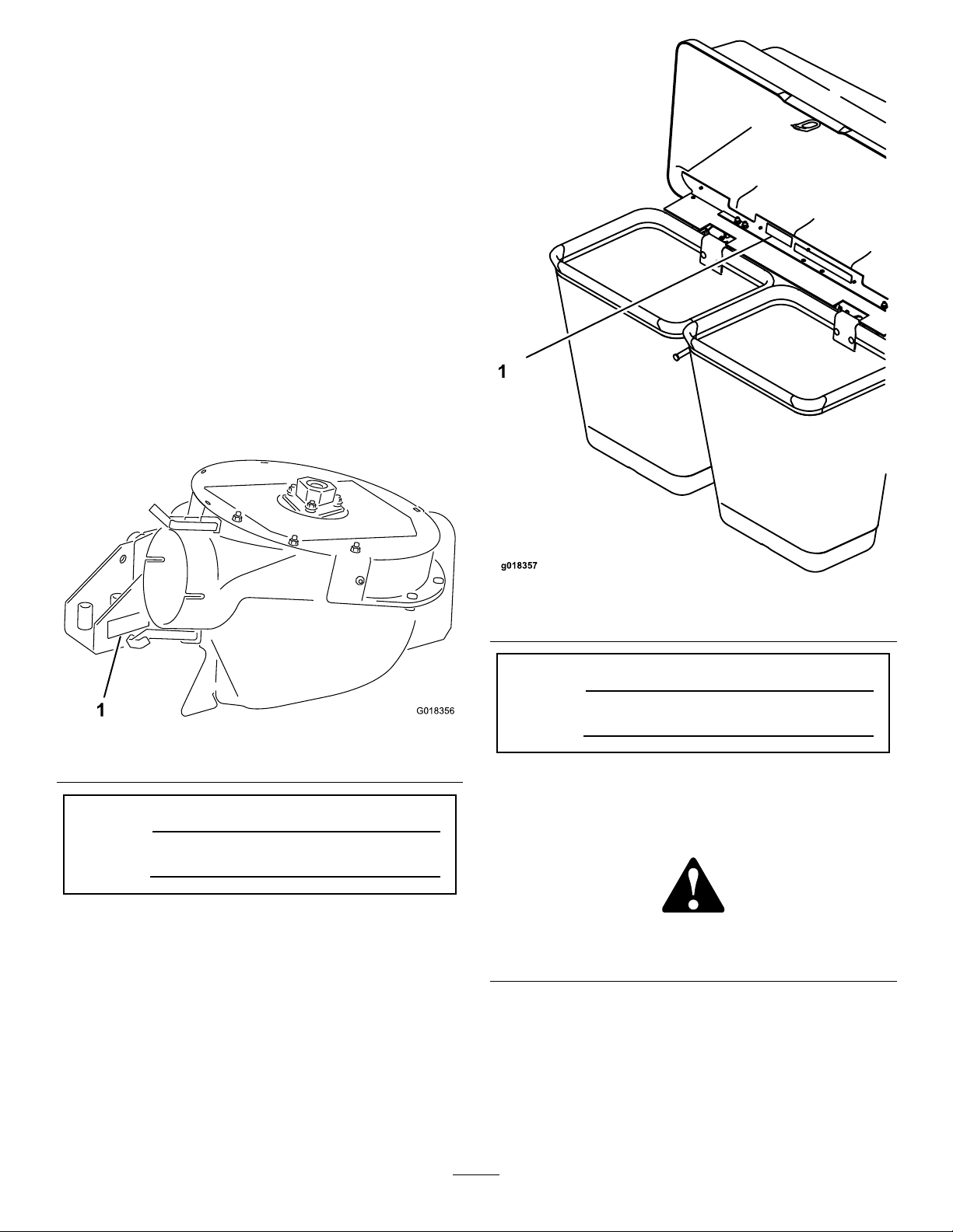
ofyourproductready .Figure1,andFigure2identifythe
locationofthemodelnumbersandserialnumbersonthe
product.Writethemodelnumberandserialnumberinthe
spaceprovided.
Figure2
1.Baggermodelandserialnumberlocation
ModelNo.
Figure1
1.Blowermodelandserialnumberlocation
SerialNo.
Thismanualidentiespotentialhazardsandhassafety
messagesidentiedbythesafety-alertsymbol(Figure3),
ModelNo.
SerialNo.
whichsignalsahazardthatmaycauseseriousinjuryordeath
ifyoudonotfollowtherecommendedprecautions.
Figure3
1.Safety-alertsymbol
Thismanualuses2wordstohighlightinformation.
Importantcallsattentiontospecialmechanicalinformation
andNoteemphasizesgeneralinformationworthyofspecial
attention.
©2012—TheToro®Company
8111LyndaleAvenueSouth
Bloomington,MN55420
Contactusatwww.Toro.com.
2
PrintedintheUSA
AllRightsReserved
Page 3

Contents
Safety
Safety...........................................................................3
SafetyandInstructionalDecals.................................4
Setup............................................................................5
1PreparingtheMower.............................................6
2InstallingtheSideBumpersandSupport
Brackets.............................................................6
3InstallingtheTailpipeExtension.............................7
4DrillingtheExhaust-ShieldMounting
Holes.................................................................9
5InstallingtheExhaustShield..................................11
6InstallingtheHopperSupportFrameandHood
Rod...................................................................12
7InstallingtheHoodBafe.....................................13
8InstallingtheHoodAssemblyandBags...................14
9RoutingtheBlowerBeltintotheBlower
Assembly...........................................................16
10InstallingtheBlowerAssembly.............................17
11InstallingtheBeltCover......................................19
12InstallingtheDischargeTube...............................19
13InstallingtheWeights..........................................23
14CheckingtheTirePressure..................................25
Operation....................................................................25
EmptyingtheGrassBags.........................................26
ClearingObstructionsfromtheBagger
System..............................................................26
RemovingtheBagger..............................................26
UsingtheGrassDeector.......................................27
TransportingMachines............................................27
OperatingTips......................................................27
Maintenance.................................................................29
RecommendedMaintenanceSchedule(s)......................29
PreparingforMaintenance.......................................29
CleaningtheHoodScreen.......................................29
CleaningtheBaggerandBags...................................29
InspectingtheBlowerBelt.......................................29
ReplacingtheBlowerBelt........................................29
GreasingtheIdlerArm...........................................30
InspectingtheBagger.............................................30
InspectingtheMowerBlades...................................30
ChoosingtheMowerBlades.....................................30
ReplacingtheGrassDeector..................................30
Storage........................................................................31
Troubleshooting...........................................................32
ThefollowinglistcontainssafetyinformationspecictoToro
productsandothersafetyinformationyoumustknow.
•Becomefamiliarwiththesafeoperationoftheequipment,
withtheoperatorcontrols,andsafetysigns.
•Useextracarewithgrasscatchersorotherattachments.
Thesecanchangetheoperatingcharacteristicsandthe
stabilityofthemachine.
•Followthemanufacturer'srecommendationsforadding
orremovingwheelweightsorcounterweightstoimprove
stability.
•Donotuseagrasscatcheronsteepslopes.Aheavy
grasscatchercouldcauselossofcontroloroverturnthe
machine.
•Slowdownanduseextracareonhillsides.Besureto
travelintherecommendeddirectiononhillsides.Turf
conditionscanaffectthemachine'sstability.Useextreme
cautionwhileoperatingneardrop-offs.
•Keepallmovementonslopesslowandgradual.Donot
makesuddenchangesinspeed,directionsorturning.
•Thegrasscatchercanobstructtheviewtotherear.Use
extracarewhenoperatinginreverse.
•Usecarewhenloadingorunloadingthemachineintoa
trailerortruck.
•Neveroperatewiththedischargedeectorraised,
removedoraltered,unlessusingagrasscatcher.
•Keephandsandfeetawayfrommovingparts.Donot
makeadjustmentswiththeenginerunning.
•Stoponlevelground,disengagedrives,chockorblock
wheels,shutofftheenginebeforeleavingtheoperator's
positionforanyreasonincludingemptyingthegrass
catcheroruncloggingthechute.
•Ifyouremovethegrasscatcher,besuretoinstallany
dischargedeectororguardthatmighthavebeen
removedtoinstallthegrasscatcher.Donotoperatethe
mowerwithouteithertheentiregrasscatcherorthegrass
deectorinplace.
•Shutofftheenginebeforeremovingthegrasscatcheror
uncloggingthechute.
•Useastick,notyourhands,toremoveanobstruction
fromtheblowertube.
•Donotleavegrassingrasscatcherforextendedperiods
oftime.
•Grasscatchercomponentsaresubjecttowear,damage
anddeterioration,whichcouldexposemovingpartsor
allowobjectstobethrown.Frequentlycheckcomponents
andreplacewithmanufacturer'srecommendedparts,
whennecessary.
3
Page 4
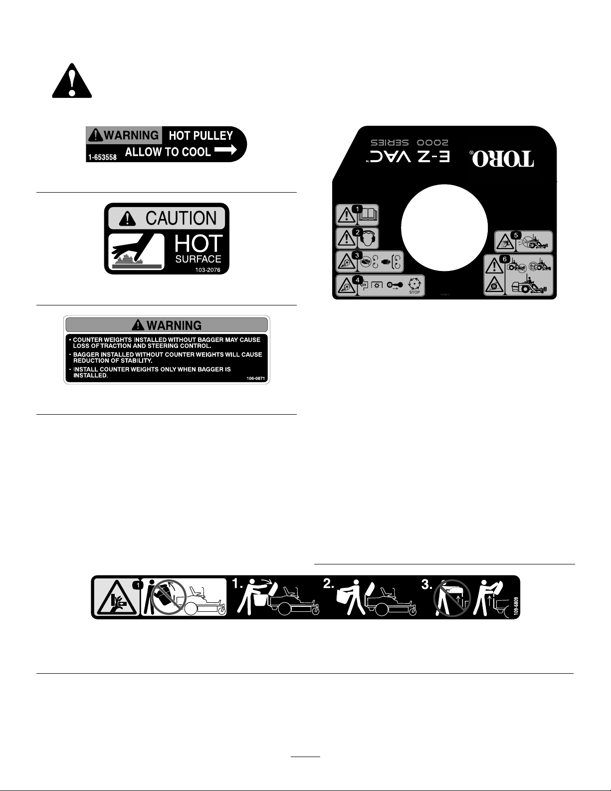
SafetyandInstructionalDecals
Safetydecalsandinstructionsareeasilyvisibletotheoperatorandarelocatednearanyareaofpotential
danger.Replaceanydecalthatisdamagedorlost.
1-653558
103–2076
121–3212
1.Warning—readthe
Operator’sManual.
106-0871
2.Warning—wearhearing
protection.
3.Cutting/dismemberment
hazard,impeller—keep
handsawayfrommoving
parts;keepallguardsin
place.
4.Cutting/dismemberment
hazard,
impeller—disengage
thePTO,removethekey
fromtheignition,waitfor
allmovingpartstostop.
5.Thrownobjecthazard—do
notruntheblowerwithout
thecollectionsystem
installedandlatched.
6.Warning;lossof
traction/control
hazard—ultravac
counterbalanceweight(s)
installedwithoutultravac
maycauselossoftraction
andsteeringcontrol;
ultravacinstalledwithout
ultravaccounterbalance
weight(s)willcause
reducedstability;install
theweight(s)onlywhen
ultravacisinstalled.
109–6809
1.Crushinghazardofhand—donotremovethewholebaggerfromthemachine:1.Openthebaggertop.2.Removethebag(s)
fromthebagger.3.Donotremovethebaggertopwhenitisclosed;openthebaggertopandthenremoveit.
4
Page 5

Setup
LooseParts
Usethechartbelowtoverifythatallpartshavebeenshipped.
ProcedureDescription
1
2
3
4
5
6
7
8
9
10
11
12
Nopartsrequired
Leftbumper
Leftframe-supportbracket
Rightbumper1
Rightframe-supportbracket
Carriagebolt(3/8x1-1/4inches)
Flangenut(3/8inch)
Tailpipeextension1
Washer-headscrew(#8x1/2inch,
self-threading)
Exhaustshield1
Flange-hex-headbolt(3/8x1inch)
Nut(3/8inch)
Exhaustshield1
Flange-hex-headbolt(3/8x1inch)
Nut(3/8inch)
Hopper-supportframe
Hairpin2
Hoodhold-downrod1
Baggerhood1
Bafe
Hairpin(small)
Hoodassembly1
Bag2
Blower(fromthebloweranddrivekit)
Blowerbelt(fromthebloweranddrive
kit)
Blowerassembly(fromtheblowerand
drivekit)
Spring(fromthebloweranddrivekit)
Beltcover(fromthebloweranddrivekit)
Coverknob
Upperdischargetube1
Screw(1/4x3/4inch)
Locknut(1/4inch)
Lowerdischargetube1
Qty.
Use
–
1
1
1
6
6
1
2
2
3
3
1
1
2
1
1
1
1
1
1
3
3
Preparethemower.
Installthesidebumpersandsupport
brackets.
Installthemuferextension.
Drilltheexhaust-shieldmountingholes.
Installtheexhaustheatshield.
Installthebaggermountingbrackets.
Installthehoodbafe.
Installthehoodassemblyandbags.
Routetheblowerbeltintotheblower
assembly.
Installtheblowerassembly .
Installthebeltcover.
Installthedischargetubes.
5
Page 6

ProcedureDescription
13
Weight-mountbracket1
Carriagebolt(5/16x3/4inch)
Flangenut(5/16inch)
Frontweight3
Bolt(3/8x1inch)
Lockwasher6
Flatwasher6
Flangenut(3/8inch)
Qty.
Use
2
2
6
3
Installtheweights.
14
Note:Determinetheleftandrightsidesofthemachinefromthenormaloperatingposition.
1
PreparingtheMower
Nopartsrequired
2
InstallingtheSideBumpers andSupportBrackets
NoPartsRequired
Partsneededforthisprocedure:
Procedure
Performthefollowingproceduretopreparethemowerfor
attachingtheblowerandbaggerkit.
1.DisengagethePTO,movethemotion-controllevers
totheNEUTRALlockedposition,andsettheparking
brake.
2.Shutofftheengine,removethekey ,andwaitforall
movingpartstostopbeforeleavingtheoperating
position.
3.Repairallbentordamagedareasofthemowerdeck
andreplaceanymissingparts.
4.Cleanthemowerofanydebrisonthedeckorrearpart
ofthemowertoeaseinstallation.
1
1
1Rightbumper
1
6
6
Procedure
1.Removetheleftandrightbumpersasfollows:
A.Removethenutsandboltssecuringtheleftside
–
Leftbumper
Leftframe-supportbracket
Rightframe-supportbracket
Carriagebolt(3/8x1-1/4inches)
Flangenut(3/8inch)
Checkthetirepressure.
bumperandmufershieldtothechassisand
centerengineguardasshowninFigure4.
6
Page 7
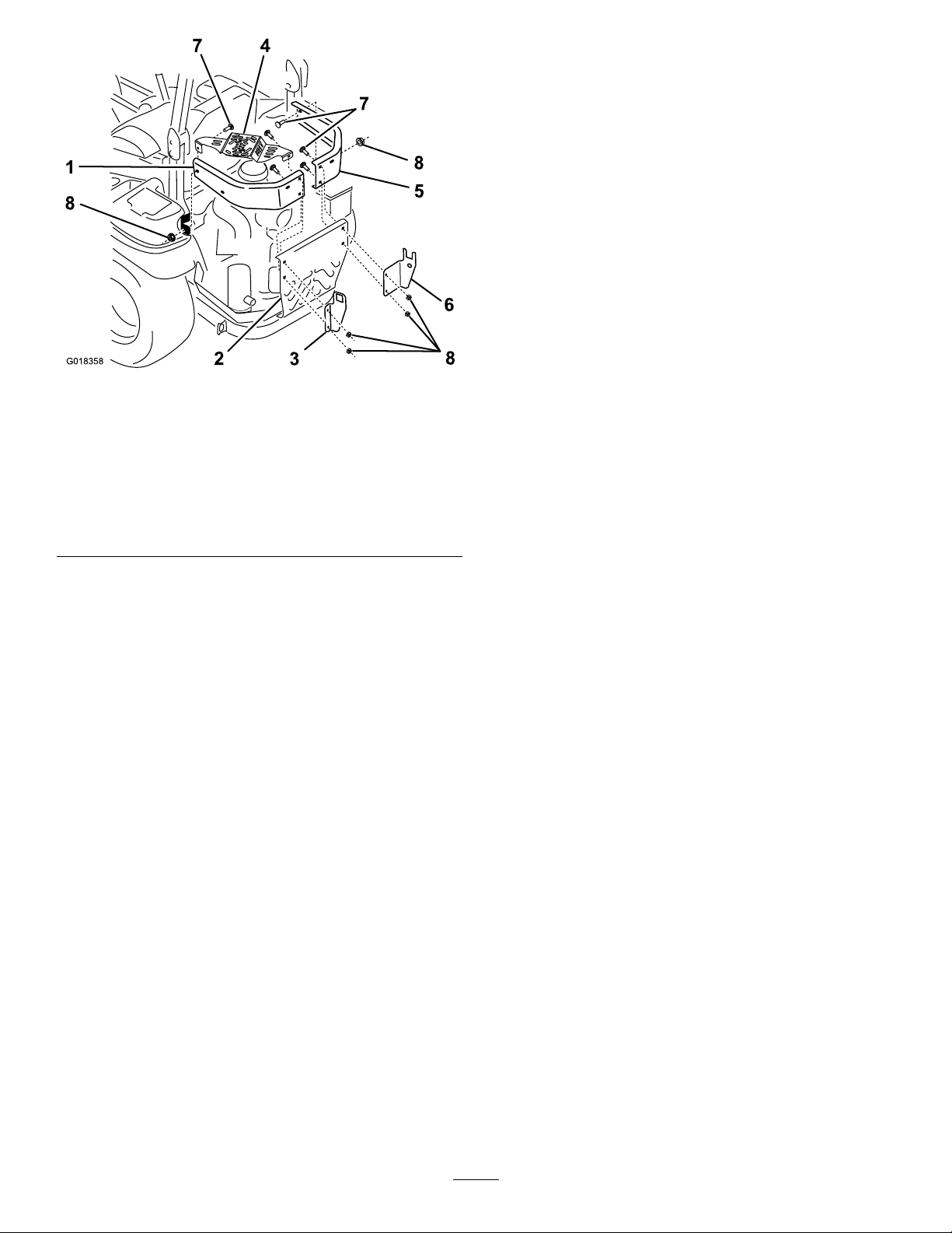
G018358
1
3
5
6
7
8
8
7
8
2
4
Figure4
SideBumperandBracketInstallation
1.Leftsidebumper
2.Centerengineguard6.Rightframe-support
3.Leftframe-supportbracket7.Carriagebolt(3/8x1-1/4
4.Mufershield8.Flangenut(3/8inch)
5.Rightsidebumper
bracket
inches)
F.Aligntheholesfortheleftframe-supportbracket,
leftsidebumperandmuferguardtotheupper
holeinthecenterengineguard(Figure4).
G.Looselysecurethebracket,bumperandmufer
guardtothecenterengineguardattheupperhole
withacarriagebolts(3/8x1-1/4inches)anda
angenut(3/8inch)(Figure4).
H.Alignthefrontholesintheleftsidebumperand
themuferguardwiththeforward-mounting
pointonthechassis.(Figure4).
I.Securethebumperandguardtothemounting
pointwithacarriagebolt(3/8x1-1/4inches)and
aangenut(3/8inch)(Figure4).
J.Tightenthehardwarethatsecuresthebracket,
bumperandmuferguardtothecenterengine
guard.
3.Installthenewrightsidebumperasfollows:
A.Alignthenewrightsidebumperwiththe
forward-mountingpointonthechassisandthe
bumper-mountingpointsonthecenterengine
guard(Figure4).
B.Alignthemountingange(theangewith2
holes)oftherightframe-supportbrackettothe
leftasshowninFigure4.
B.Removetheleftbumperandmufershieldfrom
themachine.
Note:Retainthemufershieldforinstallation
withthenewleftsidebumper.
C.Removethenutsandboltssecuringtherightside
bumpertothechassisandcenterengineguard.
Note:Discardthecarriageboltsandangenuts
thatsecuretheoriginalleftandrightsidebumpers
tothemachine.
2.Installthenewleftsidebumperasfollows:
A.Alignthenewleftsidebumperwiththe
forward-mountingpointonthechassisandthe
bumper-mountingpointsonthecenterengine
guard(Figure4).
B.Alignthemountingange(theangewith2
holes)oftheleftframe-supportbrackettotheleft
C.Aligntheholesoftherightframe-supportbracket
andbackholesoftherightsidebumperwiththe
back,centerengineguard(Figure4).
D.Looselysecurethebracketandbumpertothe
centerengineguardwith2carriagebolts(3/8x
1-1/4inches)and2angenut(3/8inch)(Figure
4).
E.Alignthefrontholeinthenewrightsidebumper
withtheforwardmountingpointonthechassis
(Figure4).
F.Securethebumpertothemountingpointwith
acarriagebolt(3/8x1-1/4inches)andaange
nut(3/8inch)(Figure4).
G.Tightenthehardwarethatsecuresthebracketand
bumpertothecenterengineguard.
asshowninFigure4.
C.Aligntheholesoftheleftframe-supportbracket
andthebackholesoftheleftsidebumperwith
theholesinthecenterengineguard(Figure4).
D.Looselysecurethebracketandbumpertothe
centerengineguardatthelowerholewitha
carriagebolt(3/8x1-1/4inches)andaangenut
(3/8inch)(Figure4).
E.Positionthemuferheatshieldwiththemounting
angesinsidetheleftsidebumper(Figure4).
7
Page 8
3
4
3
5
3
62
4
3
3
5
61
G018372
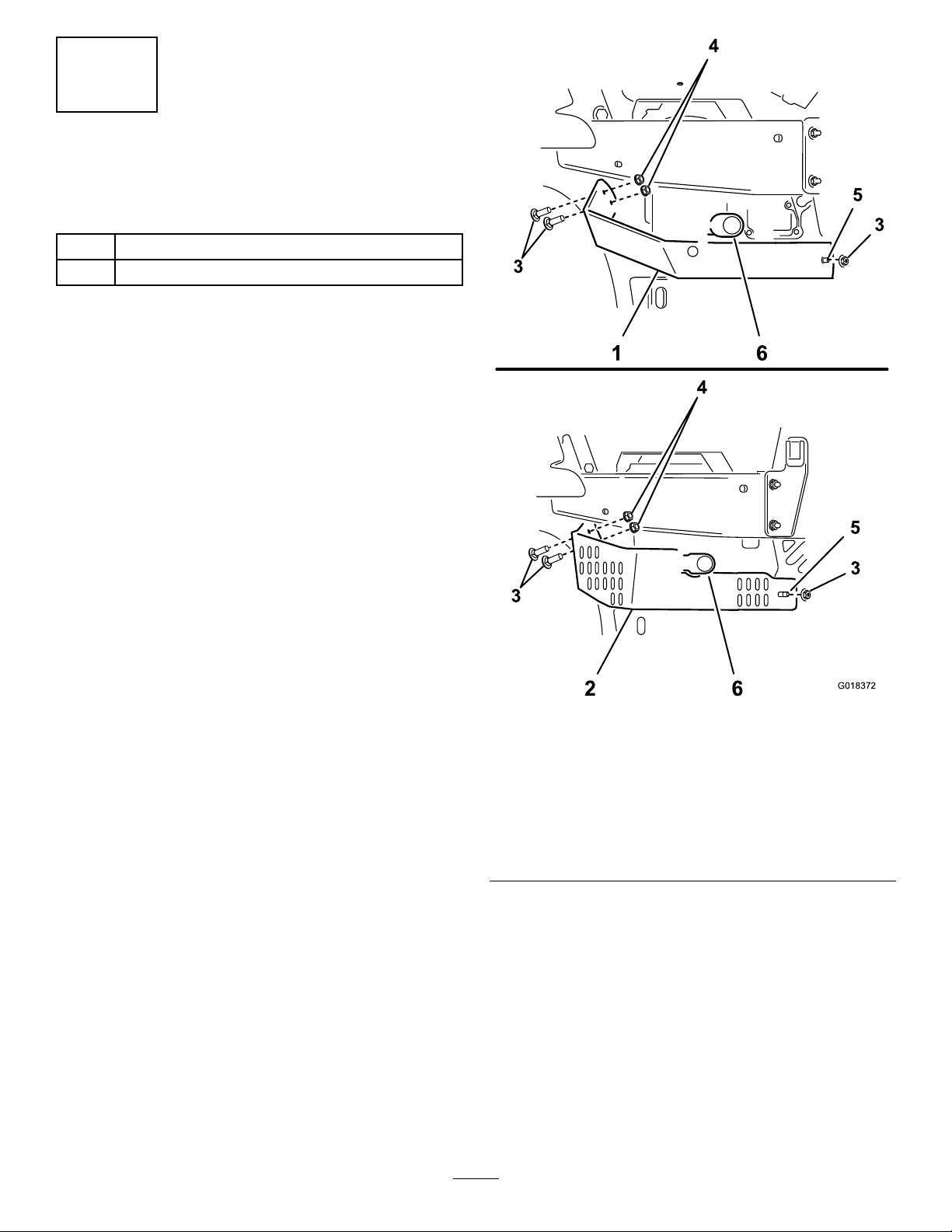
InstallingtheTailpipe
Extension
Partsneededforthisprocedure:
1Tailpipeextension
1
Washer-headscrew(#8x1/2inch,self-threading)
Procedure
Installthetailpipeextensionasfollows:
1.Locatethemufertailpipeatthelowerleftcornerof
theengine.
Note:Ifyouneedadditionalroomtoinstallthe
tailpipeextension,dothefollowingsteps:
A.Removethe3angenutsthatsecurelower-left
engineguardtothemachine(Figure5).
Note:Retaintheseparts.
Figure5
1.Lower-leftengineguard
(USdomesticmowers)
2.Lower-leftengineguard
(Internationalmowers)
3.Carriagebolt(frontmount
point)
Lower-LeftEngineGuard
4.Flangenut
5.Carriagebolt(center
engineguard)
6.Mufertailpipe
B.Removethe2carriageboltsatthefront-mount
2.Measure19mm(3/4inch)alongtheoutsideofthe
pointandthelower-leftengineguard.(Figure5).
Note:Retaintheseparts.Donotremovethe
carriageboltatthecenterengineguard.
mufertailpipe,fromtheoutletendmovingtowardthe
muferasillustratedinFigure6,andmarkthesurface
ofthetailpipeatthismeasurement.
8
Page 9
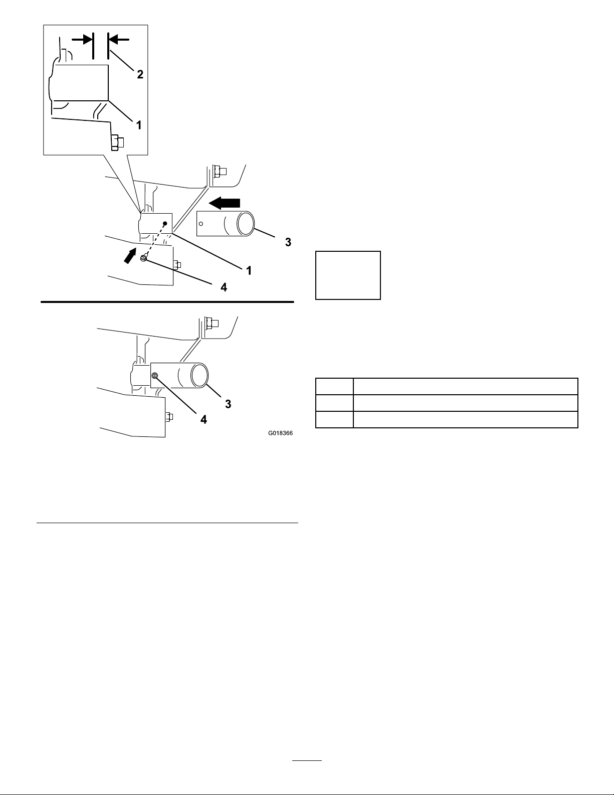
G018366
1
2
3
4
3
4
1
8.Securethetailpipeextensionwiththeself-threading
screw(#8x1/2inch)(Figure6).
Note:Dothefollowingstepstoinstalltheengine
guardifremovedinstep1:
A.Aligntheholesintheguardwithbacksideofthe
front-mountingpointandthecenterengineguard
(Figure5).
B.Looselysecurethelowerengineguardtothe
carriageboltatthecenterengineguardwithone
ofthepreviouslyretainedangenuts(Figure5).
C.Securethelowerengineguardtothefront
mountingpointwiththepreviouslyretained
carriageboltsandangenuts(Figure5).
D.Tightenallthemountinghardwaretosecurethe
lower-leftengineguard.
4
DrillingtheExhaust-Shield
Figure6
TailpipeExtensionInstallation
1.Mufertailpipe
2.3/4inch(19mm)4.Washerheadscrew(#8x
3.Slipthepre-drilledendofthetailpipeextensionover
themufertailpipe,andaligntheendoftheextension
withthemarkcreatedinstep2.Rotatethetailpipe
extensionuntilthepre-drilledholeintheextensionis
alignedoutwardandhorizontal(Figure6).
4.Marktheoutlineoftheholeinthetailpipeextension
ontothemufertailpipe,andremovethetailpipe
extension.
5.Locatethecenterofthemarkonthemufertailpipe
surface,andcenter-punchthelocation.
6.Drilla1.5mm(1/16inch)holeinthemufertailpipe
atthecenter-punchmark.
7.Slipthetailpipeextensiononthemufertailpipeand
aligntheholes.
3.Tailpipeextension
1/2inch,self-threading)
MountingHoles
Partsneededforthisprocedure:
1Exhaustshield
2
Flange-hex-headbolt(3/8x1inch)
2
Nut(3/8inch)
Procedure
Note:Iftheexhaust-shieldmountingholesarepresentin
thelower-leftengineguard,skiptotheinstructionsinsection
5InstallingtheExhaustShield(page11).
Note:Installthetailpipeextensionandthelower-leftengine
guardbeforeinstallingtheexhaust-heatshield.
Drilltheholesinthelower-leftbumperholesfortheexhaust
shieldasfollows:
1.Locatethemufertailpipeandtailpipeextensionatthe
left-rearcorneroftheengine,andlocatethelower-left
engineguard.
2.Aligntheexhaustshieldtothelower-leftengineguard
asfollows:
A.Centerthearchedpartoftheshieldtothetailpipe
extension.
B.Locateandmarktheheat-shieldmountingholes
asfollows:
•ForDomestic(US)Mowers
9
Page 10
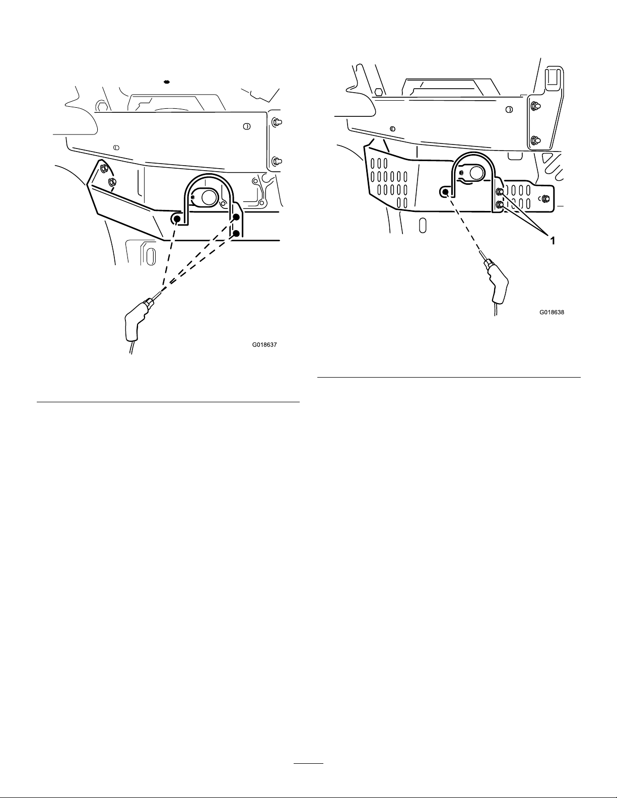
i.Aligntherightangeoftheexhaust
G018637
G018638
1
shield(theangewith2holes)tothe
rearsurfaceofthelower-leftengine
guard(Figure7).
tothetwoleft-most-verticalslotsin
thelower-leftengineguard(Figure8).
Figure7
HeatShieldInstallationonUSDomesticMower
ii.Alignthebottomedgeofthe
exhaust-shieldrightangetothe
bottomedgeoftheengineguard
(Figure7).
iii.Aligntheleftangeoftheexhaust
shield(theangewith1hole)tothe
surfaceofthesmall,angularareaof
thelower-leftengineguard.(Figure7).
Note:Ensuretheleftange(the
angewith1hole)oftheexhaust
shieldisushwiththeengine-guard
surface.
iv .Alignthetopedgeofthe
exhaust-shieldleftangeand
thetopedgeofthelower-leftengine
guardsothattheangeedgeandthe
guardedgeareparallel(Figure7).
v.Marktheoutlineofallholesinthe
exhaust-shieldangesontothe
lower-leftengineguard,andremove
theexhaustshieldfromtheengine
guard.
•ForInternational(TE)Mowers
i.Aligntheholesoftheexhaust-shield
rightange(theangewith2holes)
Figure8
HeatShieldInstallationonInternational(TE)Mower
1.Flange-hex-headbolt(3/8x1inch)andNut(3/8inch)
ii.Alignthebottomedgeoftheright
angeoftheoftheexhaustshieldto
thebottomedgeoftheengineguard
(Figure8).
iii.Looselysecuretherightangeofthe
exhaustshieldtotheengineguard
with2ange-hex-headbolts(3/8x1
inch)and2angenuts(3/8inch).
iv .Aligntheleftangeoftheexhaust
shield(theangewith1hole)to
angularareaofthelower-leftengine
guard(Figure8).
Note:Ensurethattheleftange
(theangewith1hole)oftheexhaust
shieldisushwiththeengine-guard
surface.
v.Marktheoutlineoftheholeintheleft
angeoftheexhaustshieldontothe
lower-leftengineguard.
vi.Removethefastenersandexhaust
shieldfromtheengineguard.
3.Locatethecenterofthemarksonthelower-left
engine-guardsurface,andcenter-punchthelocations.
4.Drilla10mm(3/8inch)holeintheengineguardat
thecenter-punchmarkcreatedinstep3.
10
Page 11
Important:Ensurethatthedrillbitdoes
G018364
621
1
2
3
4
4
5
notcontactthemuferwhendrillingthe
heat-shield-mountingholeinthelower-leftengine
guard.
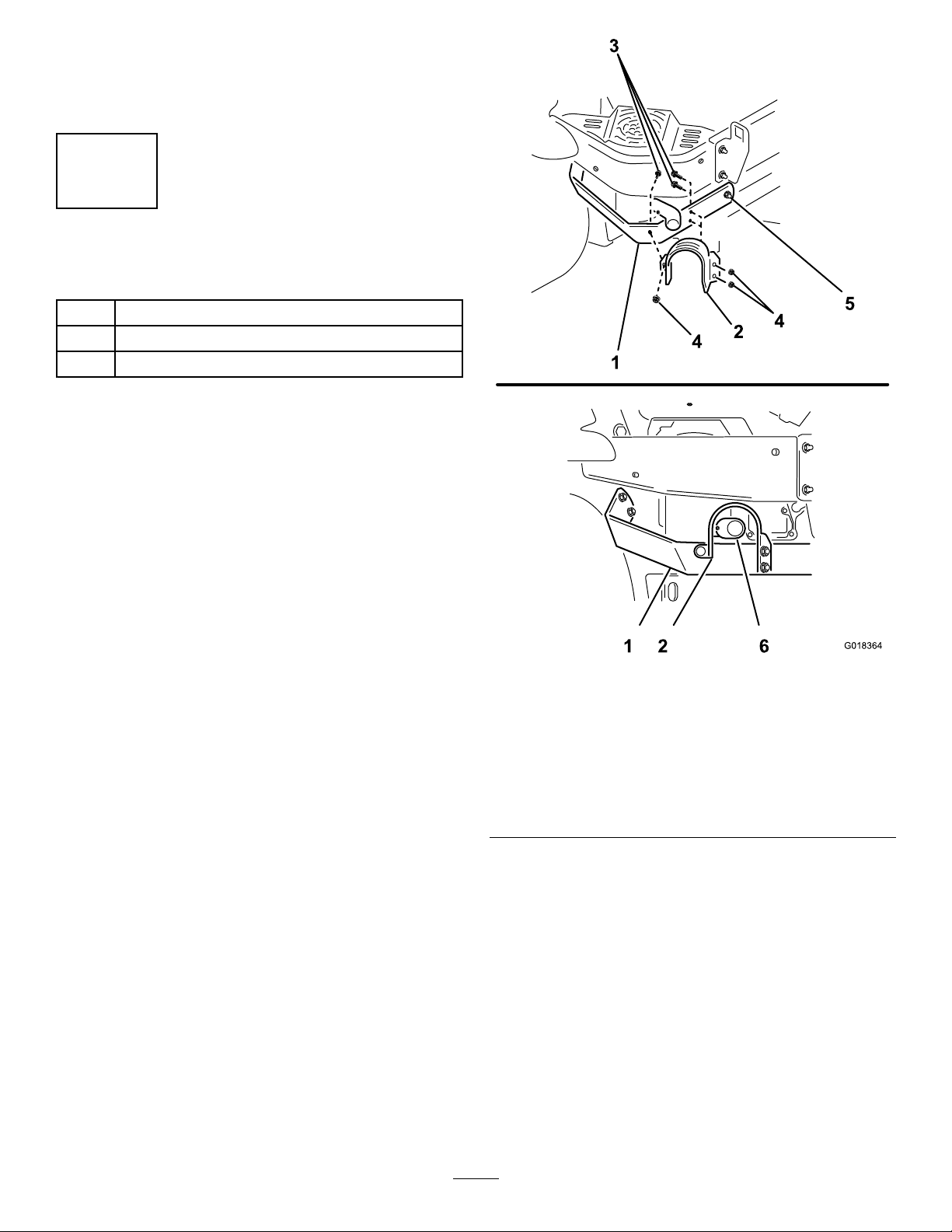
5
InstallingtheExhaustShield
Partsneededforthisprocedure:
1Exhaustshield
3
Flange-hex-headbolt(3/8x1inch)
3
Nut(3/8inch)
Procedure
Installtheexhaustguardonthelower-leftbumperasfollows:
1.Aligntheholeoftheexhaust-guardleftangetothe
holeinthesmall,angularareaoftheengineguardas
illustratedinFigure9forDomestic(US)mowersor
inFigure10forInternational(TE)mowers.
Figure9
Heat-ShieldInstallationonUSDomesticMower
1.Lower-leftengineguard4.Nut(3/8inch)
2.Exhaustshield
3.Flange-hex-headbolt(3/8
x1inch)
5.Flangenut(lower-left
engineguard,
back-mountingpoint)
6.Tailpipeextension
11
Page 12

G018365
1
2
3
4
4
5
1 2 6
6
g018359
5
1
4
3
6
2
InstallingtheHopperSupport FrameandHoodRod
Partsneededforthisprocedure:
1
Hopper-supportframe
2Hairpin
1Hoodhold-downrod
Procedure
Installthehopper-supportframeasfollows:
1.Alignthehopper-supportframesothatthe2
keyed-hoodpinsonthetopoftheframearepointing
totheright,andthemountingpinonthebottomof
theframeispointingtotheleftasshowninFigure11.
Figure10
Heat-ShieldInstallationonInternational(TE)Mower
1.Lower-leftengineguard4.Nut(3/8inch)
2.Exhaustshield
3.Flange-hex-headbolt(3/8
x1inch)
2.ForDomestic(US)Mowers,aligntheholesinthe
rightangeoftheexhaustguardwiththeholesinthe
backofthelower-leftbumper(Figure9).
5.Flangenut(lower-left
engineguard,
back-mountingpoint)
6.Tailpipeextension
ForInternational(TE)Mowers,aligntheholes
intherightangeoftheexhaustguardwiththe2
left-most-verticalslotsinthebackofthelower-left
engineguard(Figure10).
3.Securetheheatshieldtotheengineguardwiththe3
ange-hex-headbolts(3/8x1inch)and3angenuts
(3/8inch)(Figure9forUSDomestic(US)mowers
orFigure10forInternational(TE)mowers.)
Figure11
Hopper-SupportFrameInstallation
1.Hopper-supportframe4.Leftframe-supportbracket
2.Keyed-hoodpins
3.Mountingpin6.Hairpin
2.Insertthehopper-supportframeintothesquare-shaped
openingoftheleftframe-supportbracket(Figure11).
3.Alignthemountingpintotherightoftheright
frame-supportbracket(Figure11).
4.LowertheframebetweentheU-shapetabsoftheof
therightbracket(Figure11).
5.Rightframe-support
bracket
12
Page 13

5.Slidethehopper-supportframetotheleftuntilthe
g018360
1
2
3
4
G018355
1
2
3
4
5
6
mountingpinpassesthroughtheholeintheright
frame-supportbracket(Figure11).
Note:Thehopper-supportframeandthe
frame-supportbracketsareacloset.Ifnecessary,
useasoft-facedmallettopositionthehopper-frame
supportintheframebrackets.
6.Installthehairpinthroughtheholeofthemounting
pintosecuretheframetothebracket(Figure11).
Installthehoodrodasfollows:
1.Alignthehoodrodsothatthestopangeistowardthe
hopper-supportframe(Figure12).
7
InstallingtheHoodBafe
Partsneededforthisprocedure:
1Baggerhood
1
Bafe
2
Hairpin(small)
InstalltheBafeintheBaggerHood
1.Removeandretainthehairpinsfromthebafe.
2.Locatethebafeslotsinthefrontandbacksidewalls
ofthebaggerhood,andthemountingtabsonthe
hoodbafe(Figure13).
Figure12
HoodRodInstallation
1.Hoodrod
2.Stopange
2.Inserttherodthroughtheholeinthehopper-support
frameuntilthestopangeisagainstthebacksideof
theframe(Figure12).
Note:Ensurethattheholeinthehoodrodis
extendingbeyondtheforwardsideofthehopper-frame
hole.
3.Securethehoodrodtothesupportframebyinserting
thehairpinthroughtheholeinthehoodrod(Figure
12).
3.Hopper-supportframe
4.Hairpin
Figure13
Hood,Bafe,andHairpin
1.Hairpin
2.BaggerHood
3.Bafe-mountingtab
3.Positionthehoodsothattheductsealisonyourleft,
asillustratedinFigure13.
4.Alignthebafesothatthescreenedareaisupand
angledleft(Figure13).
5.Insertthebafeupintothehoodfromthebottom
(Figure13).
4.Bafeslot
5.Bafe
6.Ductseal
13
Page 14

6.Alignthebafe-mountingtabswiththebafeslotsin
g018354
1
2 3 4
6
5
1
2
3
G018608
thehood,andpushthemountingtabsupandthrough
theslots(Figure13).
7.Securethebafetothehoodbyinsertingthehairpins
intotheholesinthebafe-mountingtabsasshown
inFigure14.
Figure15
Air-CleanerCoverRemoval
1.Air-cleanercover3.Air-cleanerlatch
2.Breathervalve
2.Pulltheair-lter-coverbackandremovetheair-lter
cover.
1.Hairpin
2.Baggerhood
3.Bafe-mountingtab
8
InstallingtheHoodAssembly andBags
Partsneededforthisprocedure:
1Hoodassembly
2Bag
BaggerHoodAssembly
Figure14
4.Bafeslot
5.Bafe
6.Ductseal
Installthehoodassemblyasfollows:
1.Onthehood,locatethekeyholeslotintheleftand
right-hoodbrackets(Figure16).
2.Onthehopper-supportframe,locatethe2keyedpins
atthepivotbracketsonthetopofthehopper-support
frame(Figure16).
Procedure
Removetheair-cleanercoverasfollows:
1.Openthe2latchesthatsecuretheair-ltercovertothe
air-lterhousing(Figure15).
14
Page 15

5
2
4
G018361
1
3
1.Positiontheair-cleanercoversothatthebreathervalve
1
3
2
3
G018610
islocatedatapproximately5o’clock(Figure17).
1.Air-cleanercover3.Air-cleanerlatch
1.Hood4.Pivotbracketwith
2.Hoodbracketwithkeyhole
slot
3.Hopper-supportframe
Figure16
HoodInstallation
keyed-pivotpin
5.Hoodinstalled
2.Breathervalve
2.Securethelatches(Figure15).
Installthebagassembliesontothehopper-supportframe
asfollows:
1.Raisethehoodtoexposethenotched-bagbracketson
Figure17
Air-CleanerCover
thehopper-supportframeasshowninFigure18.
3.Rotatethehoodsothatthekeyholeslotisup,andalign
thehoodtotherightofthekeyed-pivotpins(Figure
16).
4.Assemblethehoodtothehopperframebyslidingthe
keyholebracketsoverthekeyedpins(Figure16).
5.Rotatethehooddowntosecurethehoodtothe
hopper-supportframeasshowninFigure16.
Installtheair-cleanercoverasfollows:
Note:Ensurethattheprimaryairlterisfullyseatedby
pushingonitsouterrim.
Important:Donotpressonthesoftinsideareaofthe
lter
15
Page 16

G018362
1
2
3
5
4
BagInstallation
g018363
1
2
3
G018368
1
2
3
4
Figure18
Figure19
9
RoutingtheBlowerBeltinto theBlowerAssembly
Partsneededforthisprocedure:
1
Blower(fromthebloweranddrivekit)
1
Blowerbelt(fromthebloweranddrivekit)
1.Hood4.Mounttab
2.Notched-bagbracket5.Bag
3.Hopper-supportframe
2.Alignthemounttabofthebagassemblywiththe
notched-bagbracket(Figure18).
3.Lowerthebagassemblyuntilthebagtabisfullyseated
intothenotchedbracket(Figure18).
4.Repeatsteps1and2fortheotherbag(Figure18).
5.Lowerthebaggerhoodoverthebags(Figure18).
6.Aligntheholeinthehoodlatchwiththehood
hold-downrod.(Figure19).
7.Pushthehoodlatchforwarduntiltheendofthehood
rodhaspassedthroughlatchasshowninFigure19.
Procedure
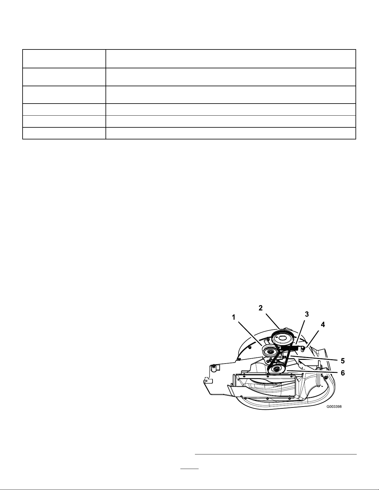
1.Installthebeltaroundtheblowerpulley(Figure20and
Figure21).
Figure20
BlowerBeltRouting
1.Drivepulley3.Blowerpulley
2.Blowerbelt
4.Idler/tensionpulley
16
Page 17
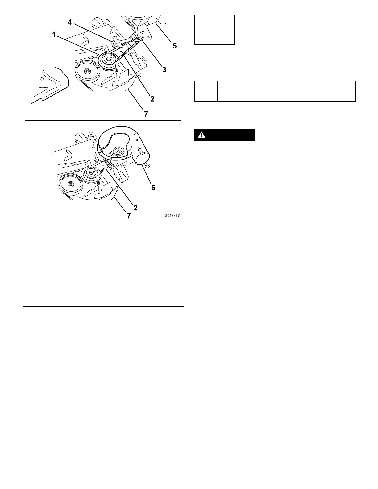
G018367
1
2
3
2
4
6
5
7
7
Figure21
BlowerBeltRouting
1.Drivepulley
2.Blowerbelt
3.Blowerpulley7.Mowerdeck
4.Idler/tensionpulley
5.Blower(housing
repositionedforillustrative
purposes)
6.Blowerinposition(housing
portionremovedfor
illustrativepurposes)
2.Ensurethatthebeltremainsalignedtotheblower
pulleywhileyouareinstallingtheblowerassembly.
10
InstallingtheBlowerAssembly
Partsneededforthisprocedure:
1
Blowerassembly(fromthebloweranddrivekit)
1
Spring(fromthebloweranddrivekit)
Procedure
WARNING
Anuncovereddischargeopeningcouldallow
thelawnmowertothrowobjectstowardyouor
bystanders,resultinginseriousinjury.Also,contact
withthebladecouldoccur.
•Neveroperatethelawnmowerunlessyouinstall
acoverplate,amulchplate,oragrasschuteand
catcher.
•Ensurethatthegrassdeectorisinstalledwhen
youremovethegrasschuteandcatcher.
Removetheside-dischargechuteasfollows:
Important:Installtheside-dischargechutewhenyou
removethebaggerandblower.
Important:Saveallthehardwareandtheside-discharge
chute.
1.Removethelocknut,bolt,spacer,andspringthatsecure
theside-dischargechutetothemowerdeck(Figure22).
Note:Retaintheremovedhardware.
2.Removethesidedischargechutefromthemowerdeck.
Note:Retainthechute.
17
Page 18

g015594
1
6 2
4
7
3
5
Figure22
4
3
2
1
G018369
G018370
1
2
3
3
4
5
7
6
4
4.Movethelatchpinfromthelockingpositiontothe
openposition(Figure24).
1.Bolt
2.Spacer6.Grassdeector
3.Locknut
4.Spring
5.Springinstalled
7.Jhookendofspring
Installtheblowerassemblyasfollows:
1.Removetheoriginalright-handbeltcoverfromthe
mowerdeck.
Note:Retaintheoriginalbeltcoverforinstallation
whenyouoperatethemowerwiththebagging-kit
blowerremoved.
2.Alignthepivotpinontheblowerwiththepivot-pin
holeinthedeck(Figure23).
3.Lowertheblowerandslidethepivotpinintothepivot
hole(Figure23).
Note:Ensurethatthebeltremainspositionedinthe
blowerpulley .
Figure24
SecuringtheBlowertotheChuteBracket
1.Blowerassembly5.Idlerpivotbracket
2.Latchpin(lockingposition)
3.Latchpin(openposition)7.Belt(beneaththeidler
4.Chutebracket
6.Idlerpulley
pulley)
5.Closetheblowerassemblyandalignthelatchpinwith
theholeinthechutebracket.
6.Movethelatchpintothelockingposition(Figure25).
Note:Ensurethatthelatchpinextendsthroughthe
holeinchutebracket.
Figure23
InstallingBlowertoDeckPivotHole
1.Blowerassembly3.Pivothole
2.Deck4.Blower-pivotpin
18
Page 19

g018371
1
2
3
9
6
8
4
7
5
11
G018445
3
2
1
4
InstallingtheBeltCover
Partsneededforthisprocedure:
1
Beltcover(fromthebloweranddrivekit)
1
Coverknob
Procedure
1.Lowerthemowerdecktothelowestheight-of-cut
position.
Figure25
InstallingtheT ensionSpringandAligningtheBelt
1.Blowerassembly
2.Latchpin(lockingposition)
3.Chutebracket8.Springhookend
4.Idlerpivotbracket
5.Fixedspringpost
Note:Ensurethatthelatchrmlyholdstheblower
assemblyagainstthemowerdeck,butcanbereleased
byhand.
7.Routethebeltaroundthedrivepulleyasillustratedin
Figure20andFigure21.
8.Temporarilyroutethebeltbeneaththeidlerpulley
(Figure25).
9.Movetheidlerpivotbrackettowardthexedspring
post.Installthespringbyaligningthespringhookon
totheidlerspringpost(Figure25).
Note:Ensurethatthespringhooksarecorrectly
positionedonthespringposts.
6.Spring
7.Idlerspringpost
9.Belt(alignedtotheidler
pulley)
2.Alignthenewright-handbeltcoverwiththebelt-cover
bracketandthenotchesinthedeckbracket.
3.Installthenewbeltcoversothatthenotchesonboth
sidesofthecovergooverthebelt-coversupportsand
securethelatch(Figure26).
10.Pullthespringloadedidlerpulleyawayfromthexed
springpost,androutethebeltaroundthemowerdeck
pulley(Figure25).
Note:Ensurethebeltisroutedaroundtheblower
pulleycorrectly.
Figure26
1.Beltcover
2.Belt-coversupport4.Notch
InstallingtheBeltCover
3.Coverknob
4.Securethenewbeltcovertothedeckbyinstallingthe
coverknobfromthebloweranddrivekitthroughthe
coverandthreadedintothebeltcoversupport(Figure
26).
19
Page 20
12
G018640
2
1
InstallingtheDischargeTube
Partsneededforthisprocedure:
1Upperdischargetube
3
Screw(1/4x3/4inch)
3
Locknut(1/4inch)
1Lowerdischargetube
Procedure
Important:Ensurethatthemowerdeckisinthelowest
height-of-cutpositionbeforeinstallingthedischarge
tubes.
Note:Remembertoinstallthegrassdeectorwhenyou
removethebaggerfromthemower;refertoReplacingthe
GrassDeector(page30).
1.DisengagethePTOandsettheparkingbrake.
2.Shutofftheengine,removethekey ,andwaitforall
movingpartstostopbeforeleavingtheoperating
position.
3.Lowerthemowerdecktothelowestheight-of-cut
position.
4.Removethebagsforviewingthetubeunderthehood.
5.Lowerandlatchthehoodforthehopper.
6.Forabaggerkitinstalledona52-inchmowerora
60-inchmower,skiptotheinstructionsforstep8.
7.Forabaggerkitinstalledona48-inchmower,cut
theupperdischargetubeasfollows:
A.Locatetheupperendoftheupperdischargetube
(Figure27).
Note:Thelowerendoftheupperdischargetube
haspre-drilledholes.
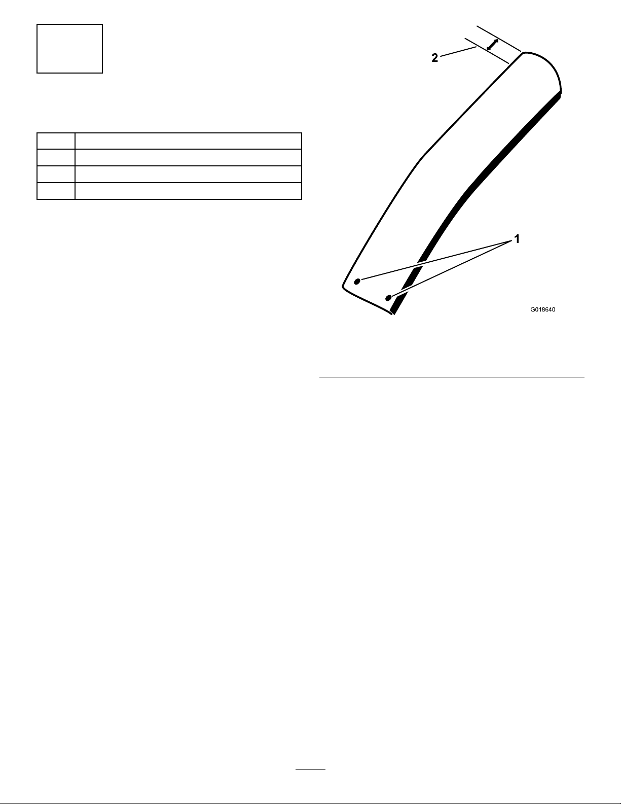
Figure27
UpperDischargeTube
1.Pre-drilledholes
B.Measure17.8cm(7inches)fromtheendofthe
tube,andmarkthetubeatthislocation(Figure
27).
C.Applymaskingtapearoundthecircumferenceof
theupperdischargetubealignedwiththemarkon
thetubecreatedinstepB(Figure27).
D.Usingtapeasaguide,carefullycutoffanddiscard
theexcesslengthoftube(Figure27).
8.Drilltheholesforthelowerdischargetubeasfollows:
A.Locatethewhitedotattheupperendofthelower
dischargetube.
B.Drillthelowerdischargetubewitha1/4inch(6.5
mm)drillbitatthecenter-punchmark(Figure28).
2.17.8cm(7inches)
20
Page 21

G018439
4
2
3
3
1
6
5
F.Usingtheremainingholesinthelowerendofthe
G018440
1
2
3
uppertubeasatemplate,drillthe2remaining
holesintheupperendofthelowerdischargetube
(Figure28).
G.Removethescrewusedtoaligntheupperand
lowertubes.
9.Installtheupperandlowerdischargetubesasfollows:
Note:Ensurethatthemowerdeckisatthelowest
cuttingpositionandthehopperbagsareremoved.
A.Inserttheupperend(noholes)oftheupper
dischargetubethroughthetubesealinthehood
bypushingthetubeinuntilthetubecontactsthe
insideofthehood,thenpullthetubeoutslightly
sothatthesealextendsoutward(Figure29).
Figure29
UpperDischargeTubeandBaggerHood
Figure28
DrillingLowerDischargeTube
1.Whitedot4.Upperdischargetube
2.Lowerdischargetube
3.Drill6.5mm(1/4inch)
diameterhole
5.Screw(1/4x3/4inch)
6.Upperdischarge-tubehole
1.Uppertube3.Baggerhood
2.Rubbersealprotrudingout
B.Alignlowerendofthelowerdischargetubewith
theblower-dischargeport.
C.Alignthenotchinthelowerdischargetubeto
lowerlatchadjacenttotheblower-dischargeport.
D.Slipthedischargetubeontheblowerportand
C.Removeandretainthehardwareinthelowerend
oftheupperdischargetube.
Note:Theholesinthelowerendoftheupper
attachthelatches.
E.Sliptheupperandlowerdischargetubestogether
(Figure30).
dischargetubearespacedanequaldistance
aroundthetubecircumference.
D.Alignoneofthepre-drilledholesatthelowerend
oftheupperdischargetubewiththeholeinthe
upperendofthelowerdischargetubethatwas
drilledinstepB(Figure28).
E.Insertascrew(1/4x3/4inches)throughoneof
theholestomaintainthealignmentoftheupper
andlowertubes(Figure28).
21
Page 22

5
G018442
3
4
1
2
3
1.Upperdischargetube
4
4
5
G01861 1
1
2
3
2.Lowerdischargetube
3.Tape(marker)
F.Rotatetheuppertubesothattheendinthehood
Figure30
TapeMarkingtheAlignedHoles
4.Hole(1/4inch)
5.Screw(1/4x3/4inches)
pointstowardsthecenterofthehood(Figure30).
Note:Thepartinglinesonthetubewillbe
approximatelyhorizontalatthehoodseal(Figure
31).
Figure31
UpperDischargeTubeandBaggerHood
1.Lowerdischargetube4.Partingline
2.Upperdischargetube
3.Baggerhood
5.Projectingendofupper
dischargetube
G.Whilemaintainingtheapproximatepositionof
theupperdischargetube,aligntheholesinthe
upperandlowerduct(Figure30).
H.Insertascrew(1/4x3/4inch)throughoneofthe
holestomaintainthealignmentoftheupperand
lowertubes(Figure30).
I.Markeachtubeontheareaadjacenttothescrew
withapieceoftape(Figure30).
Note:Accomplishmeasurementandmarking
theupperdischargetubewiththehoodclosed
andaccessedfrombeneaththehood.
J.Withthedeckinthelowestpositionandthehood
closed,lookunderneaththehoodandmeasure
thelengthoftheupperdischargetubeprotruding
intothehopper.Ifthedischargetubeextends
morethan7.6cm(3inches),removetheexcess
tubelength(Figure33).
22
Page 23

G018443
2
1 3
UpperDischargeTubeMeasurement
3
G018444
1
2
Figure32
1.7.6cm(3inches)
2.Excesstubelength
Ifnecessary,shortentheupperdischargeductas
follows:
i.Measure7.6cm(3inches)alongtheupper
dischargetubefromthetubesealtoward
theendofthetubeandmarkthetubeat
thislocation(Figure32).
ii.Removethescrewthatisaligningthe
upperandlowerdischargetubes,and
removeuppertubefromthehoodandthe
lowertubefromtheblower.
i.Applymaskingtapearoundthe
circumferenceoftheupperdischargetube
alignedwiththemarkonthetubecreated
instepi(Figure32).
ii.Usingtapeasaguide,carefullycutoffand
discardtheexcesslengthoftube.
K.Locatethetapemarkingtheholesonthelower
andupperdischargetubesappliedinstepI.
3.Tubeseal
Figure33
LowerDischargeTubeLatch
10.Unlatchthehood,installthehopperbags,andlatchthe
hood(Figure18andFigure19);referto8Installingthe
HoodAssemblyandBags(page14).
13
L.Slipthetubestogetherandaligntheholesmarked
withthetape(Figure30).
M.Securethetubesatalltheholeswiththescrews
(1/4x3/4inch)andlocknuts(1/4inch)(Figure
30).
N.Inserttheupperdischargetubethroughthetube
sealinthehoodbypushingthetubeinuntilthe
tubecontactstheinsideofthehood(Figure29).
O.Pullthetubeoutslightlysothatthesealis
extendedoutward(Figure29).
P .Sliplowerendofthelowerdischargetubeover
theblowerdischargeport,andalignthenotchin
thetubewiththelowerlatch,andsecurethelower
dischargetubethelatches(Figure33).
InstallingtheWeights
Partsneededforthisprocedure:
1Weight-mountbracket
2
Carriagebolt(5/16x3/4inch)
2
Flangenut(5/16inch)
3Frontweight
6
Bolt(3/8x1inch)
6Lockwasher
6Flatwasher
3
Flangenut(3/8inch)
Procedure
InstalltheweightstocomplywithANSI/OPEI
B71.4-2012Standard.
23
Page 24

CAUTION
Thebaggeraddsweighttotherearofthemachine
andmaycauseanunstableconditionwhichcould
resultinalossofcontrol.
1.Installtheweight-mountbracketunderthefootrest
with2carriagebolts(5/16x3/4inch)and2ange
nuts(5/16inch).
Figure34
1.Carriagebolt(5/16x3/4
inch)
2.Weight-mountbracket
3.Flangenut(5/16inch)
1.Frontweight
2.Flatwasher
3.Lockwasher
Figure35
4.Bolt(3/8x1inch)
5.Holeinfootrest
6.Flangenut(3/8inch)
2.Installthefrontweightsontopofthefootrest(Figure
35).
3.Securethefrontweightsontopofthefootrestandto
theweight-mountbracketwith6bolts(3/8x1inch),
6lockwashers,6atwashers,and3angenuts(3/8
inch)(Figure35).
Figure36
1.Weight-mountbracket3.Lockwasher
2.Flatwasher
4.Bolt(3/8x1inch)
24
Page 25
Operation
14
CheckingtheTirePressure
NoPartsRequired
Procedure
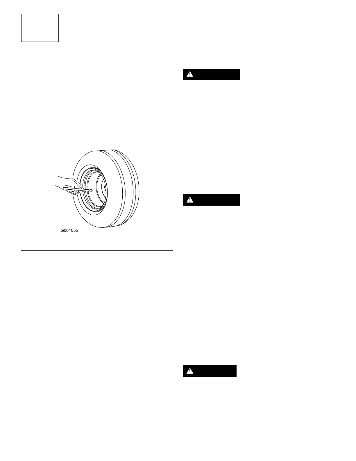
Note:Increasethetirepressureduetotheadditionalweight.
Checkandincreasetheairpressureinthefrontcasterwheels
andreartires(Figure37).
Pressureinthereartires:138kPa(20psi)
Pressureinthefrontcasterwheels:172kPa(25psi)
Note:Determinetheleftandrightsidesofthemachine
fromthenormaloperatingposition.
Important:Settheparkingbrakewhenleavingthe
machineunattended,evenifjustforafewminutes.
WARNING
Toavoidpersonalinjury,followtheseprocedures:
•Becomefamiliarwithalloperatingandsafety
instructionsinthe
mowerbeforeusingthisattachment.
•Neverremovethebaggerorbaggertubeswhile
theengineisrunning.
•Alwaysshutofftheengineandwaitforall
movingpartstostopbeforeclearingan
obstructionfromthebaggingsystem.
•Neverdomaintenanceorrepairswhilethe
engineisrunning.
•Settheparkingbrake.
Operator's Man ual
foryour
WARNING
Figure37
Withoutthegrassdeector,baggertubes,ora
completebaggerassemblymountedinplace,you
andothersareexposedtobladecontactandthrown
debris.Contactwiththerotatingmowerblade(s)
andthrowndebriswillcauseinjuryordeath.
•Alwaysinstallthegrassdeectorwhenremoving
thebaggerandchangingtoside-discharge
mode.
•Ifthegrassdeectoriseverdamaged,replaceit
immediately.Thegrassdeectorroutesmaterial
downtowardtheturf.
•Neverputyourhandsorfeetunderthemower.
•Nevertrytoclearthedischargeareaormower
bladesunlessyoumovethepowertakeoff(PTO)
toOFF,shutofftheengine,andremovethekey.
Disconnectthesparkplug(s)wires.
•Shutofftheenginebeforeuncloggingthe
dischargechute.
CAUTION
Childrenorbystandersmaybeinjuredifthey
moveorattempttooperatethemachinewhileitis
unattended.
Alwaysremovetheignitionkeyandsettheparking
brakewhenleavingthemachineunattended,even
ifjustforafewminutes.
25
Page 26
EmptyingtheGrassBags
ClearingObstructionsfrom
Grassbagsareheavywhenfull.Becarefulwhenliftingor
handlingagrassbagthatisfull.
1.DisengagethePTO,settheparkingbrake,andchock
orblockthetiresifthemachineisonaslope.
2.Unlatchthebaggerlatch.
3.Openthebaggerhood.
4.Compressthedebrisintothebags.
5.Usebothhandstoliftuponthebagandunhookit
fromthebaggerbracket.
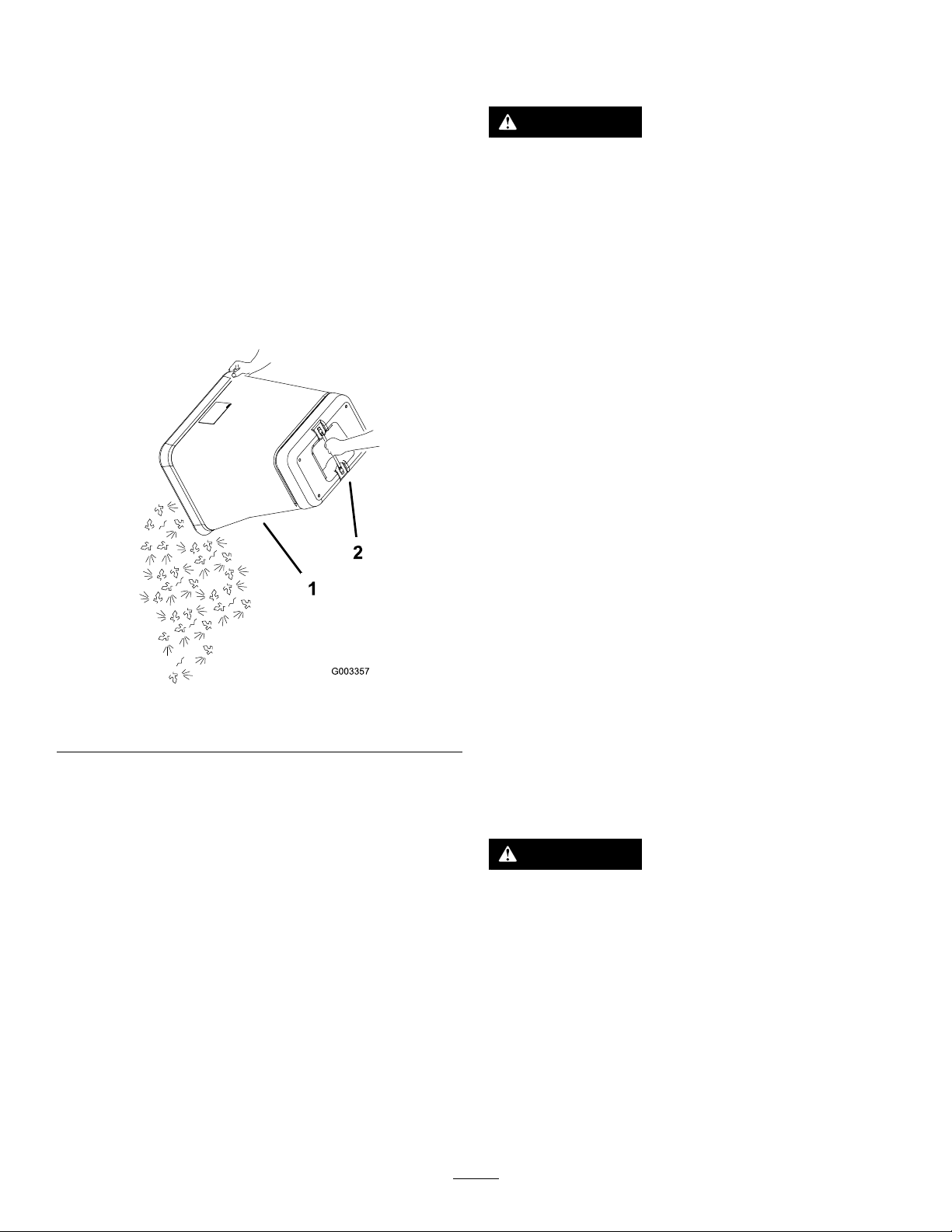
6.Grabthehandleonthebottomofthebagandtipit
overtoemptythebag(Figure38).
theBaggerSystem
WARNING
Whenthebaggerisinoperation,theblowercanbe
rotatingandcutofforinjurehands.
•Beforeadjusting,cleaning,repairingand
inspectingtheblower,andbeforeunclogging
thechute,shutofftheengine,andwaitforall
movingpartstostop.Removethekey .
•Useastick,notyourhands,toremovean
obstructionfromtheblowerandtube.
•Keepface,hands,feet,andanyotherpartof
yourbodyorclothingawayfromconcealed,
moving,orrotatingparts.
1.DisengagethePTOandsettheparkingbrake.
2.Shutofftheengine,removethekey ,andwaitforall
movingpartstostopbeforeleavingtheoperating
position.
3.Emptythebags.
4.Unlatchthelowertube.
5.Removethetubesfromthebagger.
6.Useastickorsimilarobject,notyourhands,toremove
andcleartheobstructionfromthetubeassembly .
Figure38
1.Bag2.Bottomhandle
7.Repeatstep5andstep6theotherbag.
8.Installthebagtabofeachbagintothenotchinthe
bagger-supportframe.
9.Lowerthebaggerhoodoverthebags.
10.Latchthebaggerhood.
Note:Inmostcases,youcanshakethedebrisoutof
thetubes.
7.Iftheblowerassemblyisplugged,unlatchthebagger
blowerassembly,removethebelt,andswingitopen.
8.Useastickorsimilarobject,notyourhands,toremove
andcleartheobstructionfromtheblowerassembly.
9.Afteryouremovetheobstruction,installthecomplete
baggersystemandresumeoperation.
RemovingtheBagger
WARNING
Componentsaroundenginewillbehotifthe
machinehasbeenrunning.Touchinghot
componentscancauseburns.
•Donottouchenginecomponentswhenhot.
•Allowenginetocoolbeforeremovingthebagger.
1.DisengagethePTO,settheparkingbrake,andchock
orblockthetires.
2.Shutofftheengine,removethekey ,andwaitforall
movingpartstostopbeforeleavingtheoperating
position.
3.Unlatchthelowertubefromtheblowerandremove
thetubefromtheblowerassembly.
26
Page 27

4.Removethetubefromthebaggerhood.
5.Lowerthemowerdecktothelowestheight-of-cut
position.
OperatingTips
MachineSize
6.Removetheknobandthebeltcoveroverthemower
pulleyassembly.
7.Removethebaggerbeltfromthemowerpulley
assembly.
8.Opentheblowerassembly.
9.Removetheblowerassemblyfromthepivothole.
10.Ifyouarechangingtoside-dischargemode,ensurethat
thegrassdeectorisinstalledandcanbeloweredinto
workingposition.
11.Removethehoodandbagassembly.
UsingtheGrassDeector
DANGER
Withoutthegrassdeector,dischargecover,or
completegrasscatcherassemblymountedin
place,youandothersareexposedtobladecontact
andthrowndebris.Contactwithrotatingmower
blade(s)andthrowndebriswillcauseinjuryor
death.
•Alwaysinstallthegrassdeectorwhenremoving
thebaggerandchangingtoside-discharge
mode.
Rememberthatthemachineislongerandwiderwiththis
attachmentinstalled.Byturningtoosharplyinconned
placesyoumaydamagetheattachmentorotherproperty.
Trimming
Alwaystrimwiththeleftsideofthemower.Donottrim
withtherightsideofthemowerbecauseyoucoulddamage
thebaggingtubes.
CuttingHeight
Foroptimumbaggingperformance,setthedeckheight-of-cut
toremovenomorethat51to76mm(2to3inches)or1/3of
thegrassheight,whicheverisless.Cuttingoffmorethanthis
willreducethecapacityofthevacuumsystem.
CuttingFrequency
Cutthegrassoften,especiallywhenitgrowsrapidly.Youwill
havetocutyourgrasstwiceifitgetsexcessivelylong(referto
BaggingLongGrass).
CuttingTechnique
Forbestlawnappearance,besuretoslightlyoverlapthe
mowerintothepreviouslycutarea.Thishelpsreducethe
loadontheengineandreducesthechanceofpluggingthe
blowerassemblyandtubes.
•Ifthegrassdeectoriseverdamaged,replaceit
immediately.Thegrassdeectorroutesmaterial
downtowardtheturf.
•Neverputyourhandsorfeetunderthemower.
•Nevertrytoclearthedischargeareaormower
bladesunlessyoumovethepowertakeoff
(PTO)totheOFFposition,rotatetheignition
keytoOFFandremovethekey.
TransportingMachines
Donotleavegrassordebrisinthebaggerwhiletransporting
themachine.
DANGER
Transportingthemachinewithgrassordebrisin
thebaggercandamagethemachine.
Donotleavegrassordebrisinthebaggerwhile
transportingthemachine.
BaggingSpeed
Thebaggingsystemmayplugifyoudrivetoofastandthe
enginespeedgetstooslow .Onhills,itmaybenecessary
toslowthegroundspeedofthemachine.Mowdownhill
wheneverpossible.
CAUTION
Asthebaggerlls,extraweightisaddedtotheback
ofthemachine.Ifyoustopandstartsuddenlyon
hills,youmaylosesteeringcontrolorthemachine
maytip.
•Donotstartorstopsuddenlywhengoinguphill
ordownhill.Avoiduphillstarts.
•Ifyoudostopthemachinewhengoinguphill,
disengagethePTO.Thenbackdownthehill
usingaslowspeed.
•Donotchangespeedsorstoponslopes.
BaggingLongGrass
Ifthegrassisallowedtogrowlongerthannormal,orifit
containsahighdegreeofmoisture,raisethecuttingheight
higherthanusualandcutandbagthegrassatthissetting.
27
Page 28

Thencutandbagthegrassagainusingthelower,normal
setting.
Excessivelylonggrassisheavyandmaynotbepropelled
completelyintothebagger.Ifthishappens,thetubeand
blowermayplug.Toavoidpluggingthebaggingsystem,mow
thegrassatahighheight-of-cut,thenlowerthemowerto
yournormalcuttingheightandrepeatthebaggingprocess.
BaggingWetGrass
Ifpossible,alwaystrytocutgrasswhenitisdry.Wetgrass
cancauseplugging.
ReducingPlugging
Toavoidpluggingthebaggingsystem,reducegroundspeed
andmowthegrassatahighheight-of-cut,thenlowerthe
mowertoyournormalcuttingheightandrepeatthebagging
process.
SignsofPlugging
Asyouarebagging,asmallamountofgrassclippings
normallyblowoutthefrontofthemower.Anexcessive
amountofclippingblow-outindicatesthatthebaggerisfull
orthetubeisplugged.
BaggingBlades
Formostmowingconditions,thestandardhighliftbladeswill
providethebestbaggingperformance.
TheToroAtomicbladeisrecommendedforbaggingleaves
indryconditions.Indrydustyconditions,themediumlift
orlowliftbladeswillreducedustanddirtblowoutwhile
providingeffectivebaggingairow .
ContactanAuthorizedServiceDealerfortheproperblades
fordifferentmowingconditions.
CurbClimbingandLoading
Alwaysliftthedecktothehighestpositionwhenloadingthe
machineontrailersorascending/descendingacurb.Leaving
themowerinalowerpositioncandamagethemachinewhile
loadingandgoingoveracurb.Ifacurbishigherthan152mm
(6inches),crossitatasharpanglewiththedeckfullyraised.
Useextremecautionwhenloadingthemachineontoatrailer.
28
Page 29
Maintenance
RecommendedMaintenanceSchedule(s)
MaintenanceService
Interval
Aftertherst8hours
Beforeeachuseordaily
Every25hours
Every50hours
Every100hours
MaintenanceProcedure
•Inspecttheblowerbelt.
•Inspectthebagger.
•Cleanthehoodscreen.
•Cleanthebagger.
•Inspecttheblowerbelt.
•Greasetheidlerarm.
•Inspectthebagger.
PreparingforMaintenance
Dothefollowingstepsbeforepreformingmaintenanceon
themachine:
1.Parkthemachineonalevelsurface.
2.DisengagethePTO,movethemotioncontrollevers
totheNEUTRALlockedposition,andsettheparking
brake.
3.Shutofftheengine,removethekey ,andwaitforall
movingpartstostopbeforeleavingtheoperating
position.
4.Cleanthemowerofanydebrisonthedeckorrearpart
ofthemowertoeasemaintenance.
CleaningtheHoodScreen
ServiceInterval:Beforeeachuseordaily
1.Disengagethepowertakeoff(PTO)andsetthe
parkingbrake.
2.Shutofftheengine,removethekey ,andwaitforall
movingpartstostopbeforeleavingtheoperating
position.
3.Openthebaggerhood.
4.Cleanthedebrisfromthescreen.
5.Closethebaggerhood.
InspectingtheBlowerBelt
ServiceInterval:Aftertherst8hours
Every25hours
Checkbeltsforcracks,frayededges,burnmarksoranyother
damage.Replacedamagedbelts.
ReplacingtheBlowerBelt
1.DisengagethePTO,movethemotioncontrollevers
totheNEUTRALlockedposition,andsettheparking
brake.
2.Shutofftheengine,removethekey ,andwaitforall
movingpartstostopbeforeleavingtheoperating
position.
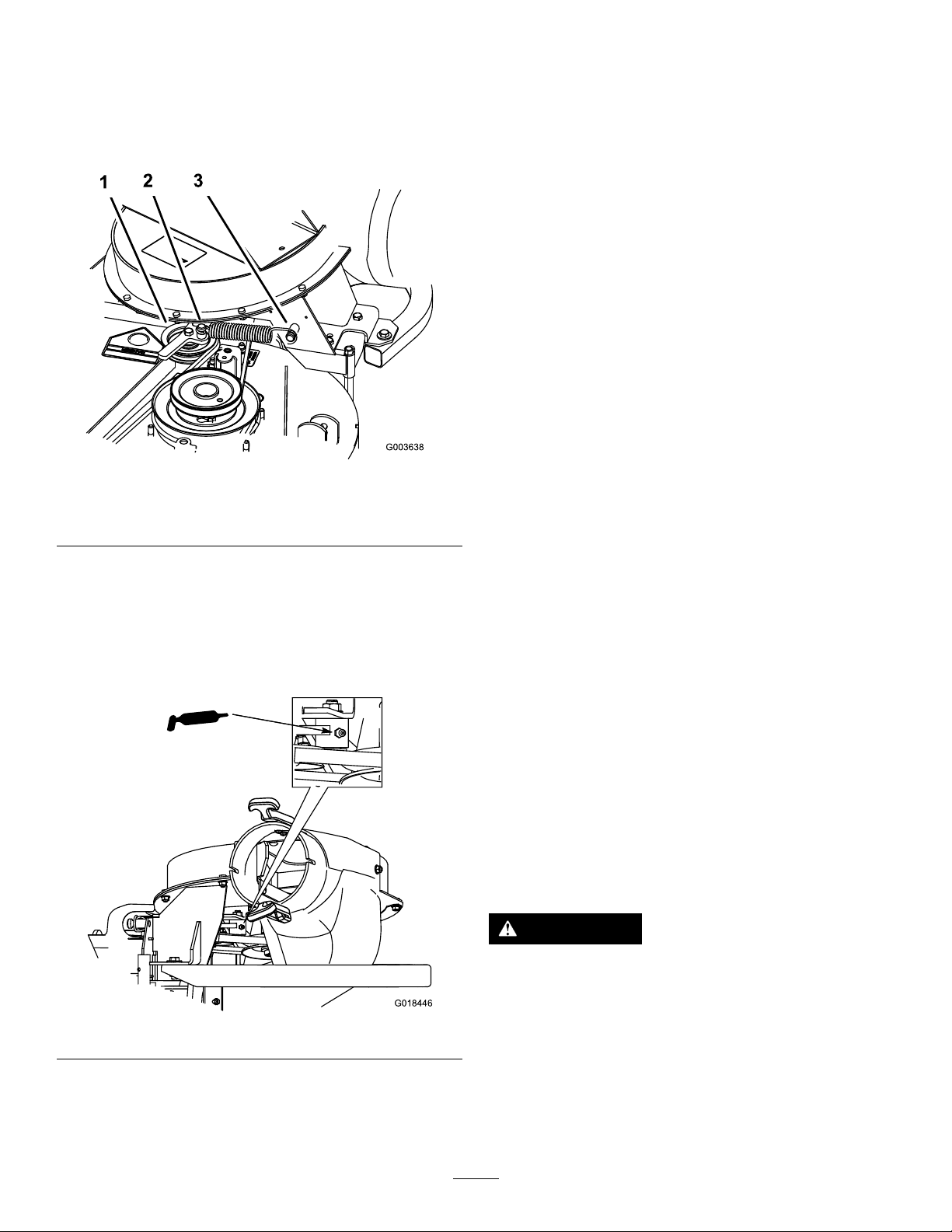
3.Pullbackonthespring-loadedidlerpulleytorelieve
thebelttension(Figure39).
CleaningtheBaggerandBags
ServiceInterval:Beforeeachuseordaily
1.Washtheinsideandoutsideofthebaggerhood,bags,
tube,andtheundersideofthemower.
Note:Useamildautomotivedetergenttoremovedirt.
2.Ensurethatyouremovemattedgrassfromallparts.
3.Afterwashingallparts,letthemdrythoroughly.
Note:Withallpartsinstalled,startandrunthemachinefor
aminutetoassistindrying.
1.Idlerpulley
2.Mower-deckpulley5.Belt
3.Spring
29
Figure39
4.Springpeg
6.Blowerpulley
Page 30
4.Removetheexistingbaggerbeltfromthemower-deck
G018446
pulleyandthentheblowerpulleys.
5.Installthenewbeltaroundtheblowerpulleysandthe
mower-deckpulley(Figure39).
6.InstallthespringasshowninFigure40.
Figure40
1.Spring-loadedidlerpulley
2.Shorthookend
7.Pullbackonthespringloadedidlerpulleyandinstall
thebeltontothespringloadedidlerpulley(Figure39).
3.Longhookend
InspectingtheBagger
ServiceInterval:Every100hours
Aftertherst8hours
1.DisengagethePTO,movethemotioncontrollevers
totheNEUTRALlockedposition,andsettheparking
brake.
2.Shutofftheengine,removethekey ,andwaitforall
movingpartstostopbeforeleavingtheoperating
position.
3.Checktheuppertube,lowertube,baggerhood,and
theblowerassembly.
Note:Replacethesepartsiftheyarecrackedor
broken.
4.Checkthebags,baggerframe,andscreen.
Note:Replaceanypartsthatarecrackedorbroken.
5.Tightenallnutsboltsandscrews.
InspectingtheMowerBlades
1.Inspectthemowerbladesregularlyandwhenevera
bladestrikesaforeignobject.
2.Ifbladesarebadlywornordamaged,installnewblades.
RefertoyourmachineOperator'sManualforcomplete
blademaintenance.
ChoosingtheMowerBlades
GreasingtheIdlerArm
ServiceInterval:Every50hours
Figure41
Inmostmowingconditions,thestandardhighliftbladeswill
providethebestbaggingperformance.
UseaToroAtomicbladeforbaggingleavesindryconditions.
Indrydustyconditions,themediumliftorlowliftblades
willreducedustanddirtblowoutwhileprovidingeffective
baggingairow .
ContactanAuthorizedServiceDealerfortheproperblades
fordifferentmowingconditions.
RefertothemowerOperator'sManualformoreinformation
oninstallingblades.
ReplacingtheGrassDeector
WARNING
Anuncovereddischargeopeningcouldallow
thelawnmowertothrowobjectstowardyouor
bystanders,resultinginseriousinjury.Also,contact
withthebladecouldoccur.
•Neveroperatethelawnmowerunlessyouinstall
acoverplate,amulchplate,oragrassdeector
andabagger.
•Ensurethatthegrassdeectorisinthedown
position.
30
Page 31

1.Removethelocknut,bolt,spring,and
g015594
1
6 2
4
7
3
5
spacerthatsecurethegrassdeectorto
thepivotbracketsonthedeck(Figure42).
Removethedamagedorworngrassdeector.
Figure42
Storage
1.Cleanthebaggerattachment;refertoCleaningthe
BaggerandBags(page29).
2.Inspectthebaggerattachmentfordamage;referto
InspectingtheBagger(page30).
3.Ensurethatthebagsareemptyandthoroughlydry.
4.Checkthebeltforwearorcracks.
5.Storethemachineinaclean,dryplace,outofdirect
sunlight.Ifyoumuststorethemachineoutside,cover
itwithaweatherproofcover.Thisprotectstheplastic
partsandextendsthelifeofthemachine.
1.Bolt
2.Spacer6.GrassDeector
3.Locknut
4.Spring
5.Springinstalled
7.J-hookendofthespring
2.Placethespacerandspringontothegrassdeector.
Place1J-hookendofthespringbehindthedeckedge.
Note:Ensurethat1J-hookendofthespringis
installedbehindthedeckedgebeforeinstallingthebolt
showninFigure42.
3.Installtheboltandnut.Place1J-hookendofthe
springaroundthegrassdeector(Figure42).
Important:Thegrassdeectormustbeable
torotate.Liftthedeectoruptothefullopen
positionandensurethatitrotatestothefulldown
position.
31
Page 32

Troubleshooting
Problem
Abnormalvibration.
Reducedbaggingperformance.
Blowerandtubesplugtoofrequently .
PossibleCauseCorrectiveAction
1.Cuttingblade(s)is/arebentor
unbalanced.
2.Blade-mountingboltisloose.2.Tightentheblade-mountingbolt.
3.Looseblowerpulleyorpulley
assembly.
4.Wornbaggerbelt.4.Replacethebelt.
5.Blowerfanblade(s)is/arebentor
unbalanced.
1.Lowenginespeed.
2.Pluggedscreeninbaggerhood.2.Removedebris,leavesorgrass
3.Loosebaggerbelt.3.Replacethebaggerbelt.
4.Apluggedtubeorblower.4.Locateandremovepluggeddebris.
5.Fullbags.5.Emptythehopper.
1.Bagsaretoofull.1.Dumpmorefrequently.
2.Lowenginespeed.
3.Grassistoowet.3.Cutgrasswhenitisdry.
4.Grassistoolong.4.Cutnomorethan51-76mm(2-3
5.Pluggedscreeninhood.5.Removedebris,leavesorgrass
6.Groundspeedistoofast.6.Drivesloweratfullthrottle.
7.Wornbaggerbelt.7.Replacebelt.
1.Installnewcuttingblade(s).
3.Tightentheappropriatepulley.
5.ContactanAuthorizedServiceDealer.
1.Alwaysoperatetheengineatfull
throttle.
clippingsfromthescreen.
2.Alwaysoperatetheengineatfull
throttle.
inches)or1/3ofthegrassheight,
whicheverisless.
clippingsfromthescreen.
Debrisblowout.
Blowerimpellerdoesnotspinfreely .
1.Bagsaretoofull.1.Dumpmorefrequently.
2.Groundspeedistoofast.
3.Mowerdeckisnotleveled.
1.Pluggedblower.1.Removedebris,leavesorgrass
2.Impellernotaligned.
2.Drivethemachineatslowground
speedwhileoperatingtheengineat
fullthrottle.
3.SeethemachineOperator'sManual
forlevelingthemowerdeck.
clippingsfromtheblowerimpeller .
2.ContactanAuthorizedServiceDealer.
32
 Loading...