

Page 1
FormNo.3371-273RevB
48in,52in,60inor72inE-ZVac™
DFSCollectionSystem
GenIIZMaster
ModelNo.78566—SerialNo.290000001andUp
ModelNo.78567—SerialNo.290000001andUp
ModelNo.78568—SerialNo.290000001andUp
®
Mower
Registeratwww.T oro.com.
OriginalInstructions(EN)
*3371-273*B
Page 2
WARNING
CALIFORNIA
Proposition65Warning
Thisproductcontainsachemicalorchemicals
knowntotheStateofCaliforniatocausecancer,
birthdefects,orreproductiveharm.
Figure2
48-and52-inchbaggerserialnumber
Introduction
Readthisinformationcarefullytolearnhowtooperateand
maintainyourproductproperlyandtoavoidinjuryand
productdamage.Youareresponsibleforoperatingthe
productproperlyandsafely.
YoumaycontactTorodirectlyatwww .Toro.comforproduct
safetyandoperationtrainingmaterials,accessoryinformation,
helpndingadealer,ortoregisteryourproduct.
Wheneveryouneedservice,genuineT oroparts,oradditional
information,contactanAuthorizedServiceDealerorToro
CustomerServiceandhavethemodelandserialnumbersof
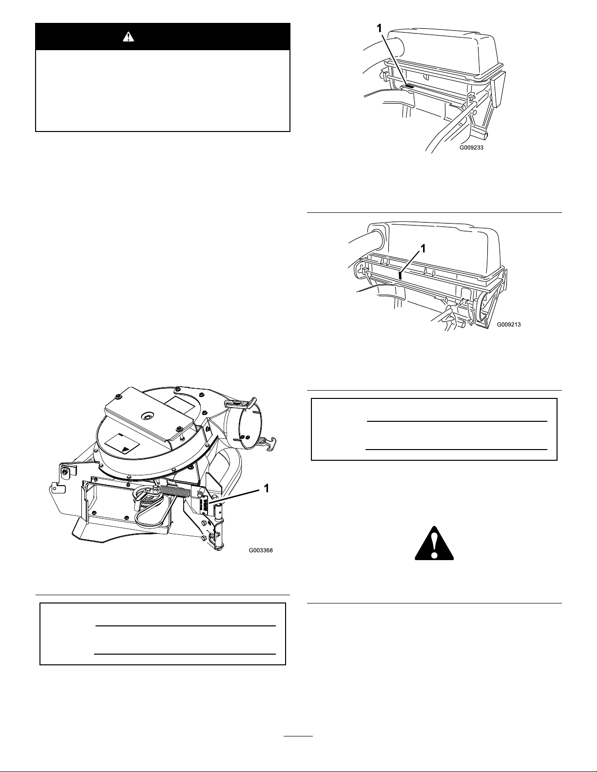
yourproductready .Figure1,Figure2andFigure3identies
thelocationofthemodelandserialnumbersontheproduct.
Writethenumbersinthespaceprovided.
1.Baggermodelandserialnumberlocation
Figure3
60-and72-inchbaggerserialnumber
1.Baggermodelandserialnumberlocation
ModelNo.
SerialNo.
Figure1
1.Collectionsystemmodelandserialnumberlocation
ModelNo.
SerialNo.
©2015—TheToro®Company
8111LyndaleAvenueSouth
Bloomington,MN55420
Thismanualidentiespotentialhazardsandhassafety
messagesidentiedbythesafetyalertsymbol(Figure4),
whichsignalsahazardthatmaycauseseriousinjuryordeath
ifyoudonotfollowtherecommendedprecautions.
Figure4
1.Safetyalertsymbol
Thismanualuses2wordstohighlightinformation.
Importantcallsattentiontospecialmechanicalinformation
andNoteemphasizesgeneralinformationworthyofspecial
attention.
Contactusatwww.Toro.com.
2
PrintedintheUSA
AllRightsReserved
Page 3

Contents
Safety...........................................................................4
SafetyandInstructionalDecals.................................4
Setup............................................................................6
1PreparingtheMower.............................................8
2InstallingtheSideBumpers....................................8
3InstallingtheBaggerMountingBrackets...................8
4InstallingtheHandleAssemblyandBracket
.........................................................................9
5InstallingtheHandleAssemblyandBracketfor
48-and52-inchMowers.......................................10
6InstallingtheBaggerAssembly..............................10
7InstallingtheMuferDeector..............................12
8RoutingtheBlowerBeltintotheBlower
Assembly...........................................................12
9InstallingtheBlowerAssembly..............................14
10InstallingtheDischargeTubes.............................16
11InstallingtheBeltCover......................................19
12InstallingtheWeights..........................................19
13InstallingtheBumpers........................................21
14AdjustingtheParkingBrake.................................22
15CheckingtheTirePressure..................................22
Operation....................................................................23
AdjustingtheBafe................................................23
EmptyingtheBagger..............................................24
ClearingObstructionsfromtheCollection
System..............................................................24
RemovingtheBagger..............................................24
UsingtheGrassDeector.......................................25
TransportingMachines............................................25
OperatingTips......................................................25
Maintenance.................................................................27
RecommendedMaintenanceSchedule(s)......................27
CleaningtheBaggerScreen......................................27
CleaningtheCollectionSystem.................................27
InspectingtheBlowerBelt.......................................28
ReplacingtheBlowerBeltfor60-and72-inch
Mowers.............................................................28
ReplacingtheBlowerBeltfor48-and52-inch
Mowers.............................................................28
CheckingandAdjustingtheBlowerLatch..................29
GreasingtheIdlerArmandHandlePivot...................29
InspectingtheCollectionSystem..............................30
AdjustingtheClosedDoorfor60-and72-inch
Mowers.............................................................30
AdjustingtheOpenDoorfor60-and72-inch
Mowers.............................................................31
AdjustingtheLatchesfor60-and72-inch
Mowers.............................................................31
AdjustingtheArmPositionfor48-and52-inch
Mowers.............................................................31
AdjustingtheClosedDoorfor48-and52-inch
Mowers.............................................................32
AdjustingtheOpenDoorfor48-and52-inch
Mowers.............................................................33
AdjustingtheParkingBrake.....................................34
InspectingtheMowerBlades...................................34
InstallingtheMowerBlades.....................................34
InstallingtheGrassDeector...................................34
Storage........................................................................35
Troubleshooting...........................................................36
3
Page 4
Safety
ThefollowinglistcontainssafetyinformationspecictoToro
productsandothersafetyinformationyoumustknow.
•Becomefamiliarwiththesafeoperationoftheequipment,
withtheoperatorcontrols,andsafetysigns.
•Useextracarewithgrasscatchersorotherattachments.
Thesecanchangetheoperatingcharacteristicsandthe
stabilityofthemachine.
•Followthemanufacturer'srecommendationsforadding
orremovingwheelweightsorcounterweightstoimprove
stability.
•Donotuseagrasscatcheronsteepslopes.Aheavy
grasscatchercouldcauselossofcontroloroverturnthe
machine.
•Slowdownanduseextracareonhillsides.Besureto
travelintherecommendeddirectiononhillsides.Turf
conditionscanaffectthemachine'sstability.Useextreme
cautionwhileoperatingneardrop-offs.Refertothe
tractionunitOperator'sManualforoperationnearslopes
anddrop-offs.
•Keepallmovementonslopesslowandgradual.Donot
makesuddenchangesinspeed,directionsorturning.
•Thegrasscatchercanobstructtheviewtotherear.Use
extracarewhenoperatinginreverse.
•Usecarewhenloadingorunloadingthemachineintoa
trailerortruck.Ifthemachineistobedrivenontoatruck
ortrailerwiththehopperfull,alwaysbackuptheramp.
•Neveroperatewiththedischargedeectorraised,
removedoraltered,unlessusingagrasscatcher.
•Keephandsandfeetawayfrommovingparts.Donot
makeadjustmentswiththeenginerunning.
•Stoponlevelground,disengagedrives,chockorblock
wheels,shutoffenginebeforeleavingtheoperator's
positionforanyreasonincludingemptyingthegrass
catcheroruncloggingthechute.
•Ifyouremovethegrasscatcher,besuretoinstallany
dischargedeectororguardthatmighthavebeen
removedtoinstallthegrasscatcher.Donotoperatethe
mowerwithouteithertheentiregrasscatcherorthegrass
deectorinplace.
•Stoptheenginebeforeremovingthegrasscatcheror
uncloggingthechute.
•Donotleavegrassingrasscatcherforextendedperiods
oftime.
•Grasscatchercomponentsaresubjecttowear,damage
anddeterioration,whichcouldexposemovingpartsor
allowobjectstobethrown.Frequentlycheckcomponents
andreplacewithmanufacturer'srecommendedparts,
whennecessary.
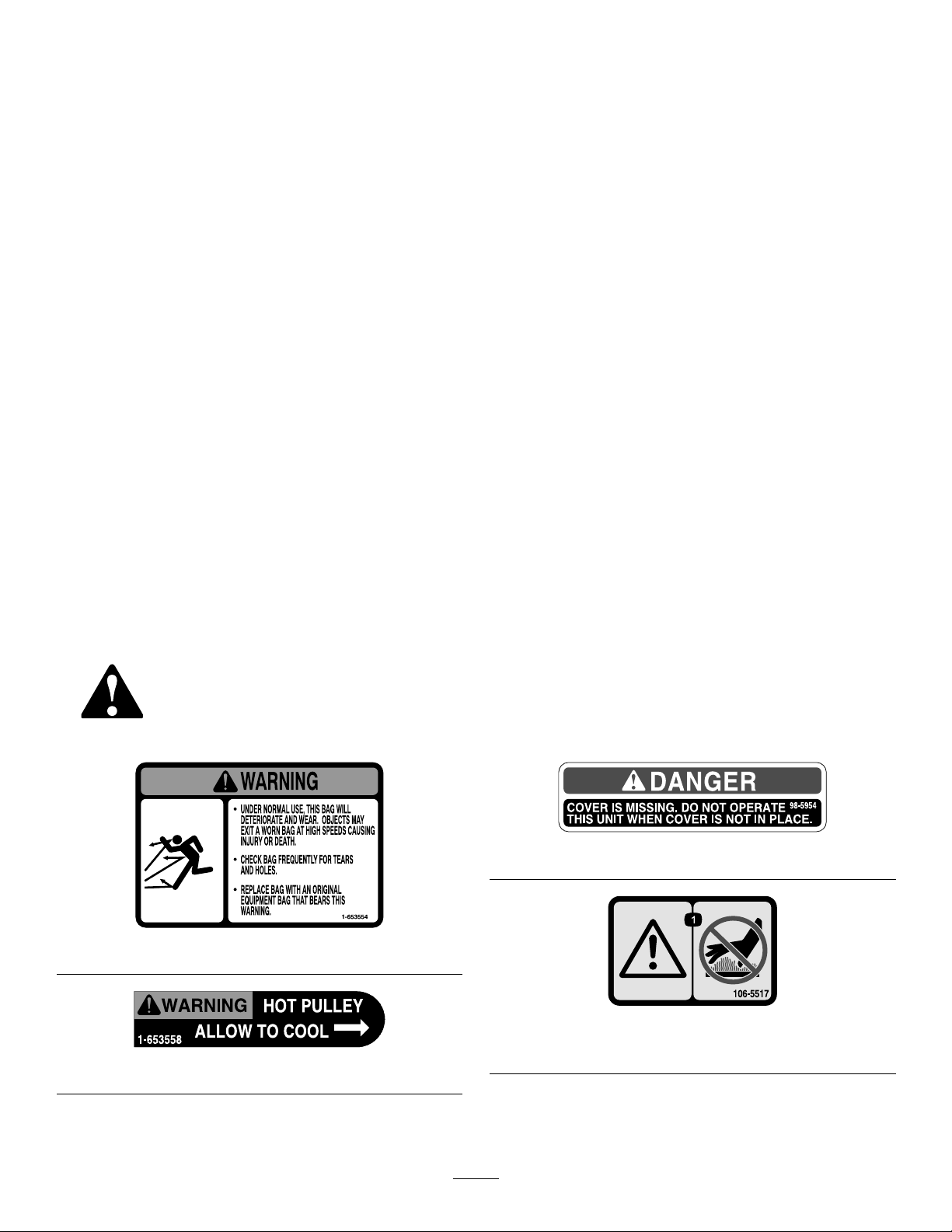
SafetyandInstructionalDecals
Safetydecalsandinstructionsareeasilyvisibletotheoperatorandarelocatednearanyareaofpotential
danger.Replaceanydecalthatisdamagedorlost.
1-653554
1-653558
98-5954
106-5517
1.Warning–Donottouchthehotsurface.
4
Page 5

106-0871
106-3339
103-3508
48-inchand52-inchdecksonly
109-5890
60-inchand72-inchdecksonly
5
Page 6

Setup
LooseParts
Usethechartbelowtoverifythatallpartshavebeenshipped.
ProcedureDescription
1
2
3
4
5
6
7
8
9
10
11
Nopartsrequired
Leftbumper
Rightbumper1
Carriagebolt(3/8x1-1/4inches)
Flangenut(largeange–3/8inch)
Uppermountingbracket1
Lowermountingbracket1
Carriagebolt(3/8x1-1/4inches)
Carriagebolt(1/2x2–1/2inches)
Flangenut(largeange–3/8inch)
Flangenut(1/2inch)
Handleassembly1
Handlebracket1
Carriagebolt(3/8x1-1/4inches)
Clevis-pinspring
Flangenut(largeange–3/8inch)
Hoodassembly1
Knob1
Carriagebolt
Baggerassembly1
Pinandhairpincotterassembly2
Muferdeector
Flangenut(smallange–3/8inch)
Carriagebolt(3/8x1-1/4inches)
Blowerbelt(fromtheBlowerandDrive
Kit)
Blowerassembly(fromtheBlowerand
DriveKit)
Spring(fromtheBlowerandDriveKit)
Uppertube1
Lowertube1
Bolt(#10x3/4inches)
Locknut(#10)
Washer(7/32inch)
Beltcover(fromtheBlowerandDrive
Kit)
Qty.
–
1
2
6
4
2
4
2
4
1
4
1
1
2
2
1
1
1
3
3
3
1Installthebeltcover.
Preparethemower.
Installthesidebumpers.
Installthebaggermountingbrackets.
Installthehandleassembly(for60-and
72-inchmowers).
Installthehoodassembly .
Installthebaggerassembly .
Installthemuferdeector.
Routetheblowerbeltintotheblower
assembly.
Installtheblowerassembly .
Installthedischargetubes.
Use
6
Page 7

ProcedureDescription
12
13
Casterweight(ifneeded)
Clevispin
Hairpincotter2
Lockwasher(3/8inch)
Weight-mountbracket1
Bolt(3/8x1inch)
Flatwasher(3/8inch)
Flangenut(smallange–3/8inch)
Carriagebolt(5/16x3/4inch)
Flangenut(5/16inch)
Frontweight(48-inch,52-inch,and
60-inchdecks)
Frontweight(72-inchdecks)
Tapbolt(3/8x1-3/4inches)
Nut(3/8inch)
Bumper2
Spacer
Locknut(5/16inch)
Qty.
Use
2
2
6
6
6
3
2
2
3
1
2
2
2
2
Installtheweights.
Installthebumpers(formachineswith
MyRide™suspensionsystem).
14
15
Nopartsrequired
Nopartsrequired
Note:Determinetheleftandrightsidesofthemachinefromthenormaloperatingposition.
–
–
Adjusttheparkingbrake.
Checkthetirepressure.
7
Page 8
1
2
PreparingtheMower
NoPartsRequired
Procedure
Performthefollowingproceduretopreparethemowerfor
attachingtheblowerandnishingkit.
1.DisengagethePTO,movethemotion-controllevers
totheNEUTRAL-LOCKEDpositionandsettheparking
brake.
2.Stoptheengine,removethekey,andwaitforallmoving
partstostopbeforeleavingtheoperatingposition.
3.Pullthesparkplugwires.
4.Repairallbentordamagedareasofmowerdeckand
replaceanymissingparts.
5.Cleanthemowerofanydebrisonthedeckorrearpart
ofthemowertoeaseinstallation.
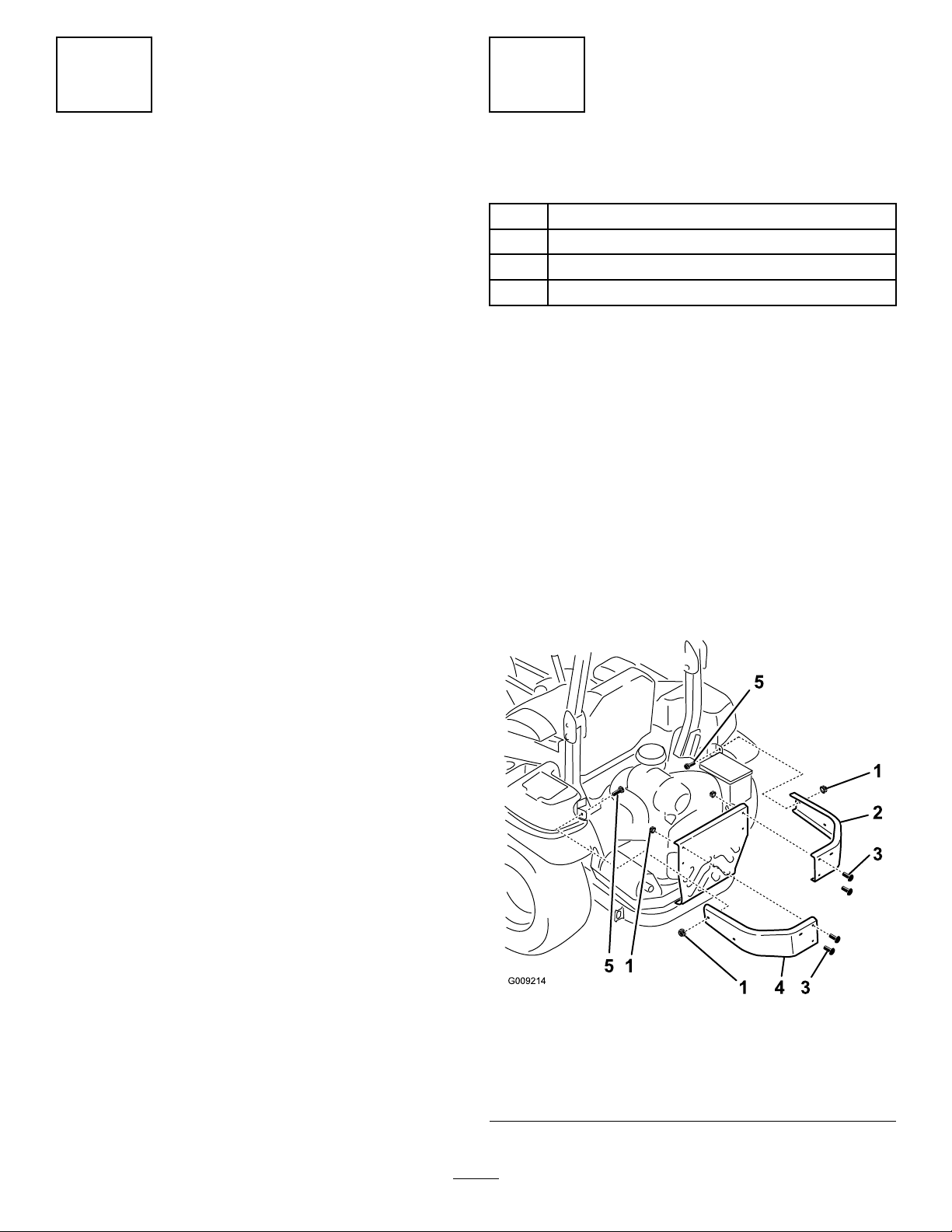
InstallingtheSideBumpers
Partsneededforthisprocedure:
1
Leftbumper
1Rightbumper
2
Carriagebolt(3/8x1-1/4inches)
6
Flangenut(largeange–3/8inch)
Procedure
1.Removethenutsandboltsholdingthesidebumpers
tothemachine(Figure5).
Note:Discardallnutsandonlythe1boltremoved
fromeachside
Note:For60-and72-inchmowers,donotinstallthe
boltandangenutfortheleftbumperneartheROPS.
Youwillinstallthemwhenyouinstallthehandle
bracketinafollowingprocedure.
2.Installthenewleftandrightbumperswith2
carriagebolts(3/8x1-1/4inches),4previously
removedcarriagebolts,and6angenuts(3/8inch)as
showninFigure5.
1.Flangenut(large
2.Rightbumper
3.Useexistingbolts
8
Figure5
4.Leftbumper
ange–3/8inch)
5.Bolt(3/8x1-1/4inches)
Page 9
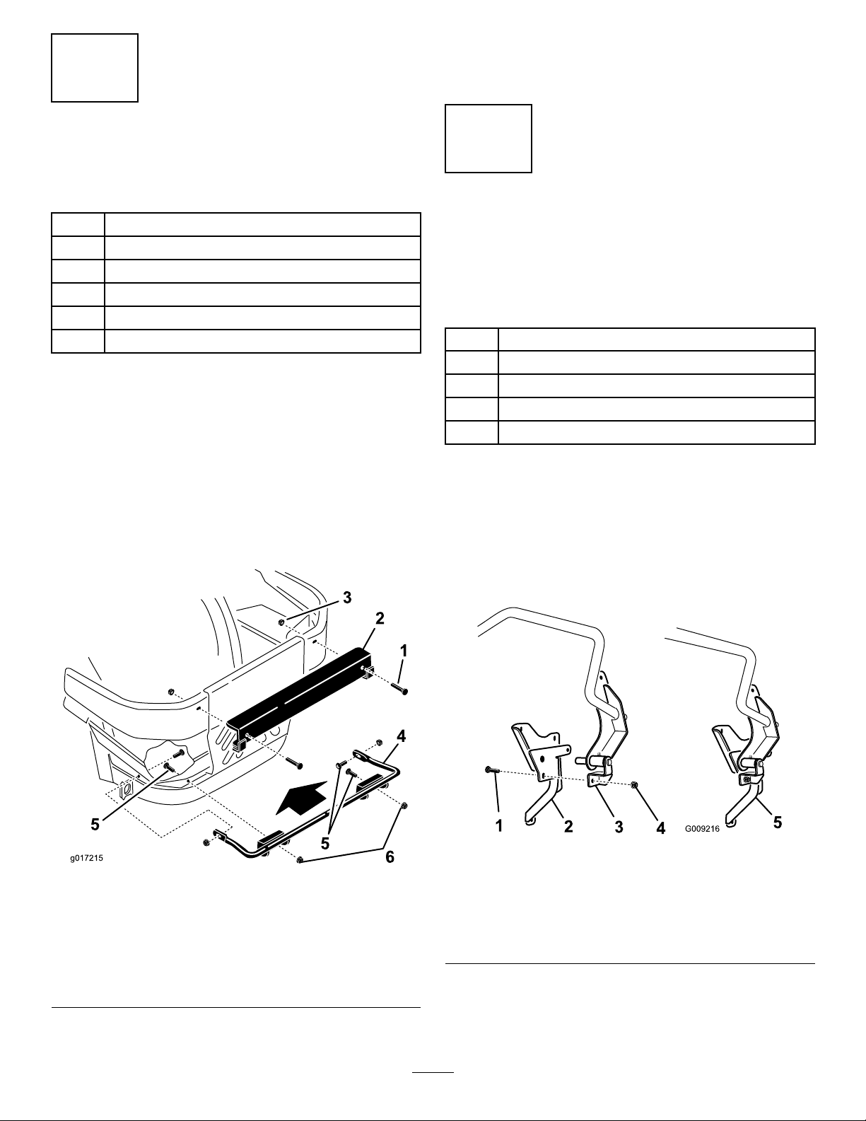
3
1
3
6
g017215
InstallingtheBaggerMounting
2.Installtheuppermountingbrackettotheleftandright
bumperswith2carriagebolts(1/2x2-1/2inches)and
2angenuts(1/2inch)asshowninFigure6.
Brackets
Partsneededforthisprocedure:
1Uppermountingbracket
1Lowermountingbracket
4
Carriagebolt(3/8x1-1/4inches)
2
Carriagebolt(1/2x2–1/2inches)
4
Flangenut(largeange–3/8inch)
2
Flangenut(1/2inch)
Procedure
Note:For60-and72-inchmowers,donotinstallthebolt
andangenutfortheleftsideofthelowermountingbracket.
Thiswillbeinstalledwheninstallingthehandlebracketin
thefollowingprocedure.
1.Installthelowermountingbrackettothemachine
framewith4carriagebolts(3/8x1-1/4inches)and
4angenuts(largeange–3/8inch)asshownin
Figure6.
4
InstallingtheHandleAssembly andBracket
60-and72-inchMowers
Partsneededforthisprocedure:
1Handleassembly
1Handlebracket
4
Carriagebolt(3/8x1-1/4inches)
1
Clevis-pinspring
4
Flangenut(largeange–3/8inch)
Procedure
1.Removetheclevis-pinspringfromthebagger-arm
assembly(seeFigure11).
2.Installthehandleassemblypinintothehandlebracket
andconnectthemtogetherwithacarriagebolt(3/8x
1-1/4inches)andaangenut(largeange–3/8inch).
Figure6
1.Carriagebolt(1/2x2-1/2
inches)
2.Uppermountingbracket
3.Flangenut(1/2inch)6.Flangenut(large
4.Lowermountingbracket
5.Carriagebolt(3/8x1-1/4
inches)
ange–3/8inch)
Figure7
1.Bolt(3/8x1-1/4inches)4.Flangenut(large
2.Handlebracket5.Assembledhandleand
3.Handleassembly
9
ange–3/8inch)
bracketassembly
Page 10
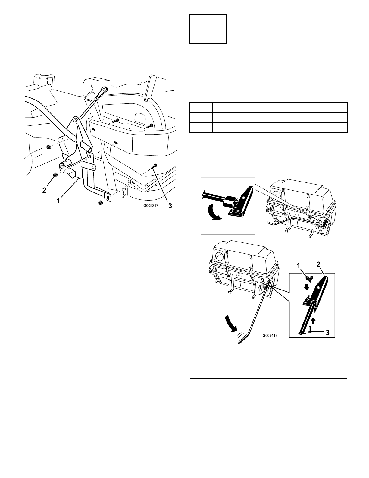
3.Installthehandleandbracketassemblytothesideof
themachinewith3carriagebolts(3/8x1-1/4inches)
and3angenuts(largeange–3/8inch)asshownin
Figure8.
5
Note:Ensurethattheboltsgothroughtheleft
bumperandthelowerbaggerbracketandconnect
themtothesideofthemachine.
Figure8
1.Handleandbracket
assembly
2.Flangenut(large
ange–3/8inch)
3.Bolt(3/8x1-1/4inches)
InstallingtheHandleAssembly andBracketfor48-and52-inch Mowers
Partsneededforthisprocedure:
1Hoodassembly
1Knob
1
Carriagebolt
Procedure
Pivotthehandleoutintothehandlebracketandsecureit
withacarriageboltandknob(Figure9).
Figure9
1.Knob
2.Handlebracket
10
3.Carriagebolt
Page 11
6
InstallingtheBagger
Assembly
Partsneededforthisprocedure:
1Baggerassembly
2Pinandhairpincotterassembly
Procedure
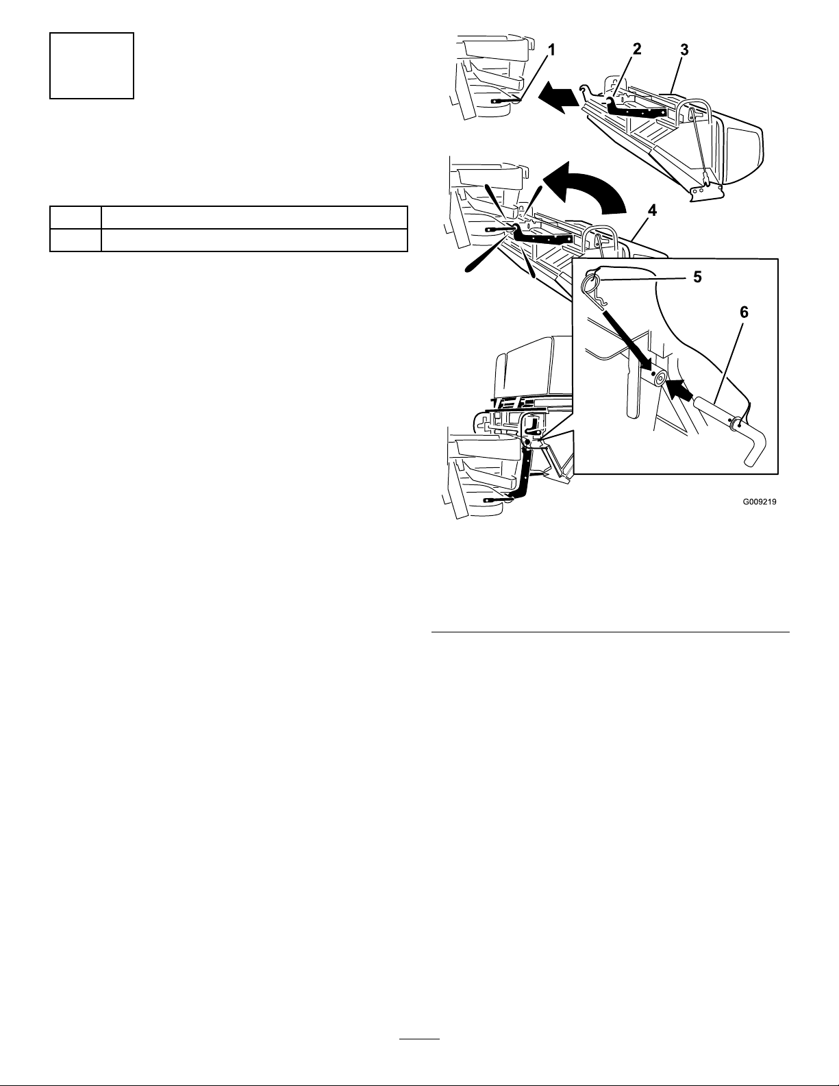
1.Positionthebaggeronitsback(Figure10).
2.Slidethehooksontothelowermountingbracket
(Figure10).
3.Rotatethebaggeruponthelowerbaggermounting
bracket.
4.Aligntheholeinthebaggerwiththeuppermounting
bracket(Figure10).
5.Installthepinandsecureitwiththehairpincotteron
bothsides(Figure10).
Figure10
1.Lowermountingbracket4.Rotatebaggerup
2.Hook5.Hairpincotterconnected
3.Bagger6.Pinconnectedtolanyard
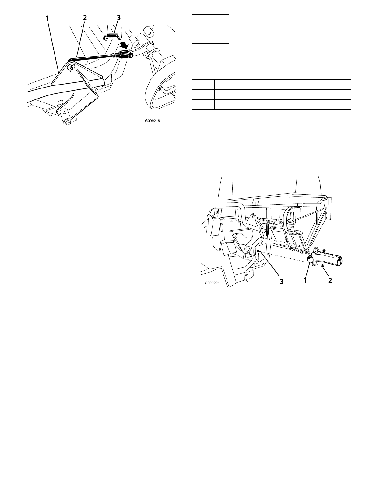
6.Rotatethebagger-handlelinkageuptothebagger
assemblyandsecureitwithaclevis-pinspring(Figure
11).
Note:Loosenandrotatetheyokeifneededtoalignit
withthebaggerassembly .
tolanyard
11
Page 12
7
InstallingtheMuferDeector
Partsneededforthisprocedure:
1
Muferdeector
2
Flangenut(smallange–3/8inch)
2
Carriagebolt(3/8x1-1/4inches)
Figure11
1.Bagger-armassembly
2.Bagger-handlelinkage4.Yoke
3.Clevis-pinspring
Procedure
Installthemuferdeectortothesideofthebaggerframe
(Figure12).
Note:Ensurethatthemuferdeectorispositionedover
thetailpipeonthemufer.
Figure12
60-and72-inchbaggershown
1.Muferdeector3.Carriagebolt(3/8x1-1/4
2.Flangenut(small
ange–3/8inch)
12
inches)
Page 13

8
RoutingtheBlowerBeltinto
theBlowerAssembly
Partsneededforthisprocedure:
1
Blowerbelt(fromtheBlowerandDriveKit)
Procedure
1.For60-and72-inchmowers,installthebeltaroundthe
blowerpulley(Figure13).
Figure13
Blowerfor60-and72-inchMowers
1.Idlerpulley4.Peg
2.Mower-deckpulley5.Belt
3.Spring
6.Blowerpulley
Figure14
Blowerfor48-and52-inchmowers
1.Spring-loadedidlerpulley
2.Mower-deckpulley6.Fixed-idlerpulley
3.Spring
4.Peg8.Belt
5.Beltguide
7.Blowerpulley
2.For48-and52-inchmowers,loosenthebeltguide
(Figure14).
3.Installthebeltaroundtheblowerpulleyandxed-idler
pulley(Figure14).
4.Tightenthebeltguide.
13
Page 14

9
InstallingtheBlowerAssembly
Partsneededforthisprocedure:
1
Blowerassembly(fromtheBlowerandDriveKit)
1
Spring(fromtheBlowerandDriveKit)
Procedure
2.Slidetheblower-assemblypegintothepivothole
(Figure16orFigure17).
WARNING
Anuncovereddischargeopeningcouldallowthe
lawnmowertothrowobjectsatyouorbystanders,
resultinginseriousinjury.Also,contactwiththe
bladecouldoccur.
•Neveroperatethelawnmowerunlessyouinstall
acoverplate,amulchplate,oragrasschuteand
catcher.
•Makesurethatthegrassdeectorisinstalled
whenyouremovethegrasschuteandcatcher.
1.Removetheside-dischargechutefromthemowerdeck
(Figure15).
Note:Saveallthehardwareandtheside-discharge
chute.Installtheside-dischargechutewhenthebagger
andblowerareremoved.
Figure16
48-and52-inchmowerdeckshown
1.Blowerassembly3.Pivothole
2.Mowerdeck4.Blower-assemblypeg
Figure17
60-and72-inchmowerdeckshown
1.Blowerassembly3.Pivothole
2.Mowerdeck4.Blower-assemblypeg
Figure15
1.Bolt
2.Spacer6.Grassdeector
3.Locknut
4.Spring8.J-hookendofthespring
5.Springinstalled
7.L-endofspring(Place
itbehindthedeckedge
beforeinstallingthebolt)
14
Page 15

3.Closetheblowerassemblytoseeifthelatchesare
adjustedcorrectly(Figure18).
5.Pullthespring-loadedidlerpulleybackandroutethe
beltaroundthemower-deckpulley(Figure20).
Note:Loosenortightentheboltsothelatchesrmly
holdtheblowerassemblyagainstthemowerdeckbut
canbereleasedbyhand
Figure18
1.Latch3.Blowerassembly
2.Bolt
4.InstallthespringasshowninFigure19.
Note:Makesurethatthehooksareinthecorrect
position.
Note:Ensurethatthebeltisroutedaroundtheblower
pulleyscorrectly
Figure20
1.Mower-deckpulley3.Blower
2.Spring-loadedIdlerpulley
1.Spring-loadedidlerpulley
2.Short-hookend
Figure19
3.Long-hookend
15
Page 16

10
InstallingtheDischargeTubes
Partsneededforthisprocedure:
1Uppertube
1Lowertube
3
Bolt(#10x3/4inches)
3
Locknut(#10)
3
Washer(7/32inch)
Procedure
Important:Makesurethatthemowerdeckisin
thelowestheight-of-cutpositionwhileinstallingthe
dischargetubes.
Note:Remembertoreplacethegrassdeectorwhenthe
baggerisremovedfromthemower.RefertoInstallingthe
GrassDeector(page34).
1.DisengagethePTOandsettheparkingbrake.
2.Stoptheengine,removethekey,andwaitforallmoving
partstostopbeforeleavingtheoperatingposition.
3.Lowerthemowerdecktothelowestheight-of-cut
position.
4.Installtheuppertubeintothebaggeropeningandpull
itbackoutsothattherubbersealisprotrudingout
(Figure21).
Figure22
1.Hoodplate
2.Uppertube
3.Hoodinthedownposition
6.Oncethe19mm(3/4inch)measurementhasbeen
achieved,marktheuppertubeontheoutsidewhere
therubbersealprotrudesout(Figure23).
Note:Thisismarkedtoensurethecorrectposition
fortheuppertubewhendrillingtheholesand
connectingtheupperandlowertubes.
Note:Therubbersealmustprotrudeoutfromthe
baggerhood.
4.3/4inch(19mm)
5.Edgeoftube
Figure21
1.Uppertube3.Baggerhood
2.Baggeropening
5.Measurethedistancethetubeisinsidethehood.
Note:Measurefromthehoodplatetotheedgeof
thetubeasshowninFigure22.Thisdistanceneeds
tobe19mm(3/4inch).
Figure23
1.Uppertube3.Baggerhood
2.Rubbersealprotrudingout4.Markhereagainstthe
rubberseal.
16
Page 17

7.Installthelowertubeintotheuppertube(Figure24).
Figure24
1.Lowertube2.Uppertube
8.Slidethelowertubeontothebootandlatchthem
together(Figure25orFigure26).
Note:Thereisalatchonthetopandbottomofthe
blowerhousing.
Note:Makesurethatthemowerdeckisinthelowest
height-of-cutpositionandthemarkontheuppertube
isstillpositionedagainsttheprotrudingrubberseal.
MakesurethatthemarkfromFigure23isstillinplace.
Figure25
1.Blowerassembly3.Latch
2.Lowertube
17
Page 18

9.Usingthe3holesorindentationsintheuppertubeasa
template,drill3holes(7/32inchdiameter)wherethe
upperandlowertubesjointogether(Figure27).
Figure26
60-and72-inchbaggershown
1.Blowerassembly3.Latch
2.Lowertube
Figure27
1.Baggerhood4.Lowertube
2.Uppertube5.Blowerassembly
3.Drill7/32inchdiameter
holeshere(usetheupper
tubeasatemplate)
10.Removethelowertubefromtheblower.
18
Page 19

11.Jointheupperandlowertubeswith3bolts(#10x
1
2
G009305
G009303
1
2
3/4inches),3atwashers(7/32inch),and3locknuts
(#10)asshowninFigure28.
Figure29
48-and52-inchbaggershown
1.Beltcover3.Notch
2.Belt-coversupport
Figure28
1.Lowertube
2.Uppertube
3.Flatwasher(7/32inch)
12.Installthelowertubeontotheblowerhousingand
secureitwiththelatches.
4.Locknut(#10)
5.Bolt,(#10x3/4inches)
11
InstallingtheBeltCover
Partsneededforthisprocedure:
1
Beltcover(fromtheBlowerandDriveKit)
Procedure
1.Lowerthemowerdecktothelowestheight-of-cut
position.
2.Installthenewbeltcoversothatthenotchesonboth
sidesgooverthebelt-coversupportsandsecurethe
latch(Figure29orFigure30).
Figure30
60-and72-inchbaggershown
1.Beltcover3.Notch
2.Belt-coversupport
19
Page 20

12
InstallingtheWeights
Partsneededforthisprocedure:
2
Casterweight(ifneeded)
2
Clevispin
2Hairpincotter
6
Lockwasher(3/8inch)
1Weight-mountbracket
6
Bolt(3/8x1inch)
6
Flatwasher(3/8inch)
3
Flangenut(smallange–3/8inch)
2
Carriagebolt(5/16x3/4inch)
2
Flangenut(5/16inch)
3
Frontweight(48-inch,52-inch,and60-inchdecks)
1
Frontweight(72-inchdecks)
2
Tapbolt(3/8x1-3/4inches)
2
Nut(3/8inch)
Procedure
3.Tightenthetapboltsothatittouchestheframeand
thentightenthejamnutagainsttheweight.
Figure31
1.Tapbolt(3/8x1-3/4
inches)
2.Nut(3/8inch)5.Clevispin
3.Casterweight
4.Hairpincotter
6.Installthetapboltagainst
theframeandtightenthe
nut.
TocomplywithANSI/OPEIB71.4-2004Standard,youmust
addweightstothemachine.
CAUTION
Thebaggeraddsalotofweighttotherearofthe
machineandmaycauseanunstablecondition,
whichcouldresultinalossofcontrol.
Thefollowingtableshowswhatweightsyouusewhenyou
installabagger.
Frontweights
used
48-inchmower
deckwithbagger
52-inchmower
deckwithbagger
60-inchmower
deckwithbagger
72-inchmower
deckwithbagger
30
30
32
12
1.Installcasterweightsonthefrontcasterswithaclevis
pinandhairpincotter(Figure31).
2.Installthenut(3/8inch)ontoeachtapbolt(3/8x
1-3/4inches)andinstallthetapboltsintoeachweight
(Figure31).
Casterweights
used
4.Installtheweight-mountbracketunderthefootrest
with2carriagebolts(5/16x3/4inch)and2ange
nuts(5/16inch).
Figure32
1.Carriagebolt(5/16x3/4
inch)
2.Weight-mountbracket
3.Flangenut(5/16inch)
5.Installthefrontweightsontopofthefootrest(Figure
33).
20
Page 21

6.Securethefrontweightsontopofthefootrestandto
theweight-mountbracketwith6bolts(3/8x1inch),
6lockwashers(3/8inch),3angenuts(smallange)
(3/8inch)and6atwashers(3/8inch)(Figure33).
13
InstallingtheBumpers
MachineswithMyRide™Suspension
System
Partsneededforthisprocedure:
2Bumper
2
Spacer
2
Locknut(5/16inch)
Procedure
For48-inch,52-inch,and60-inchdecks,installthebumpers
tothe2outsideholesofthetoeboard(Figure35).
Figure33
1.Frontweight
2.Flatwasher(3/8inch)5.Holeinfootrest
3.Lockwasher(3/8inch)6.Flangenut(small
4.Bolt(3/8x1inch)
ange–3/8inch)
1.Locknut(5/16inch)
2.Spacer
Figure35
3.Bumper
Figure34
1.Weight-mountbracket
2.Flatwasher(3/8inch)4.Bolt(3/8x1inch)
3.Lockwasher(3/8inch)
21
Page 22

For72-inchdecks,installthebumperstothe2insideholes
ofthetoeboard(Figure36).
Figure36
15
CheckingtheTirePressure
NoPartsRequired
Procedure
Note:Increasethetirepressureduetotheadditionalweight.
Checkandincreasetheairpressureinthefrontcasterwheels
andthereartires(Figure37).
Pressure:Reartires:138kPa(20psi)
Frontcasterwheels:172kPa(25psi)
1.Locknut(5/16inch)
2.Spacer
3.Bumper
14
AdjustingtheParkingBrake
NoPartsRequired
Procedure
Makesurethatthebrakeisadjustedproperly;refertothe
Operator’sManualforthemachine.
Figure37
22
Page 23

Operation
Note:Determinetheleftandrightsidesofthemachine
fromthenormaloperatingposition.
Important:Settheparkingbrakewhenyouleavethe
machine,evenifjustforafewminutes.
WARNING
CAUTION
Childrenorbystandersmaybeinjuredifthey
moveorattempttooperatethetractorwhileitis
unattended.
Alwaysremovetheignitionkeyandsettheparking
brakewhenleavingthemachineunattended,even
ifjustforafewminutes.
Toavoidpersonalinjury,followtheseprocedures:
•Becomefamiliarwithalloperatingandsafety
instructionsinthe
machinebeforeusingthisattachment.
•Neverremovethebaggerorbaggertubeswhile
theengineisrunning.
•Alwaysshuttheengineoffandwaitforall
movingpartstostopbeforeclearingan
obstructionfromthebaggingsystem.
•Neverdomaintenanceorrepairswhilethe
engineisrunning.
•Settheparkingbrake.
Operator's Man ual
foryour
WARNING
Withoutthegrassdeector,baggertubesor
completecollectionsystemmountedinplace,you
andothersareexposedtobladecontactandthrown
debris.Contactwiththerotatingmowerblade(s)
andthrowndebriswillcauseinjuryordeath.
AdjustingtheBafe
AdjustthebafetopositionB(middleposition)forbagging.
RefertotheOperator’sManualforthemachineforthebafe
adjustmentprocedure.
Figure38
•Alwaysinstallthegrassdeectorwhenyou
removethecollectionsystemandchangeto
side-dischargemode.
•Ifthegrassdeectoriseverdamaged,replaceit
immediately.Thegrassdeectorroutesmaterial
downtowardtheturf.
•Neverputyourhandsorfeetunderthemower.
•Nevertrytoclearthedischargeareaormower
bladesunlessyoumovethepowertakeoff
(PTO)tooffandrotatetheignitionkeytooff.
Alsoremovethekeyandpullthewireoffthe
sparkplug(s).
•Turnofftheenginebeforeuncloggingthe
dischargechute.
•Neveruseyourhandstounclogthedischarge
chute,useastickorsimilarobject.
23
Page 24

EmptyingtheBagger
1.DisengagethePTOandsettheparkingbrake.
2.Liftthehandletoopenthedoorandemptythehopper.
3.Pushthehandledowntoclosethedoor(Figure39).
7.Iftheblowerassemblyisplugged,unlatchtheblower
assembly,removethebelt,andswingitopen.
Important:Useastickorsimilarobject,notyour
hands,toremoveandcleartheobstructionfrom
theblowerassembly.
Note:Ifyoudrivethemachineontoatruckortrailer
whilethehopperisfull,alwaysbackuptheramp.This
willreducethechanceofrearwardtip.
Figure39
ClearingObstructionsfrom theCollectionSystem
WARNING
Whenyouoperatecollectionsystem,theblower
rotatesandcancutofforinjurehands.
•Beforeadjusting,cleaning,repairingand
inspectingtheblower,andbeforeunclogging
thechute,turnofftheengineandwaitforall
movingpartstostop.Removethekey.
•Useastick,notyourhands,toremovean
obstructionfromtheblowerandtube.
•Keepface,hands,feet,andanyotherpartof
yourbodyorclothingawayfromconcealed,
moving,orrotatingparts.
1.DisengagethePTOandsettheparkingbrake.
2.Turnofftheengine,removethekey,andwaitforall
movingpartstostopbeforeleavingtheoperating
position.
8.Afteryouremovetheobstruction,installthecomplete
collectionsystemandresumeoperation.
RemovingtheBagger
WARNING
Componentsaroundenginewillbehotifthe
machinehasbeenrunning.Touchinghot
componentscancauseburns.
•Donottouchenginecomponentswhenthey
arehot.
•Allowenginetocoolbeforeremovingthebagger.
1.DisengagethePTO,settheparkingbrake,andchock
orblockthetires.
2.Turnofftheengine,removethekey,andwaitforall
movingpartstostopbeforeleavingtheoperating
position.
3.Unlatchthelowertubefromtheblowerandremove
thetubefromtheblowerassembly.
4.Removethetubefromthebaggerhood.
5.Lowerthemowerdecktothelowestheight-of-cut
position.
6.Unlatchthebeltcoveroverthemower-pulleyassembly.
7.Removetheblowerbeltfromthemower-pulley
assembly.
8.Opentheblowerassembly .
9.Removetheblowerassemblyfromthepivothole.
10.Ifyouarechangingtoside-dischargemode,ensurethat
thegrassdeectorisinstalledandcanbeloweredinto
workingposition.
11.Removethecollectionsystemassembly .
3.Emptythebagger.
4.Unlatchthelowertube.
5.Removethetubesfromthebagger.
6.Useastickorsimilarobject,notyourhands,toremove
andcleartheobstructionfromthetubeassembly .
Note:Inmostcases,thedebriscanbeshakenoutof
thetubes.
24
Page 25

UsingtheGrassDeector
DANGER
Withoutthegrassdeector,dischargecover,or
completegrasscatcherassemblymountedin
place,youandothersareexposedtobladecontact
andthrowndebris.Contactwithrotatingmower
blade(s)andthrowndebriswillcauseinjuryor
death.
•Alwaysinstallthegrassdeectorwhenremoving
thecollectionsystemandchangingtoside
dischargemode.
•Ifthegrassdeectoriseverdamaged,replaceit
immediately.Thegrassdeectorroutesmaterial
downtowardtheturf.
•Neverputyourhandsorfeetunderthemower.
CuttingFrequency
Cutthegrassoften,especiallywhenitgrowsrapidly.You
needtocutyourgrasstwiceifitgetsexcessivelylong(referto
BaggingLongGrassBaggingLongGrass(page25)).
CuttingTechnique
Forbestlawnappearance,besuretoslightlyoverlapthe
mowerintothepreviouslycutarea.Thishelpsreducethe
loadontheengineandreducesthechanceofpluggingthe
blowerassemblyandtubes.
BaggingSpeed
Thebaggingsystemmayplugifyoudrivetoofastandthe
enginespeedgetstooslow .Onhills,youmayneedtoslow
thegroundspeedofthemachine.Mowdownhillwhenever
possible.
•Nevertrytoclearthedischargeareaormower
bladesunlessyoumovethepowertakeoff
(PTO)totheoffposition,rotatetheignitionkey
tooffandremovethekey .
TransportingMachines
DANGER
Transportingthemachinewithgrassordebrisin
thebaggercandamagethemachine.
Donotleavegrassordebrisinthebaggerwhile
transportingthemachineonatrailerortruck.
OperatingTips
MachineSize
Rememberthatthemachineislongerandwiderwiththis
attachmentinstalled.Ifyouturntoosharplyinconned
places,youmaydamagetheattachmentorotherproperty.
Trimming
Alwaystrimwiththeleftsideofthemower.Donottrim
withtherightsideofthemowerbecauseyoucoulddamage
thebaggingtubes.
CuttingHeight
CAUTION
Asthebaggerlls,extraweightisaddedtotheback
ofthemachine.Ifyoustopandstartsuddenlyon
hills,youmaylosesteeringcontrolorthemachine
maytip.
•Donotstartorstopsuddenlywhengoinguphill
ordownhill.Avoiduphillstarts.
•Ifyoudostopthemachinewhengoinguphill,
disengagethePTO.Thenbackdownthehill
usingaslowspeed.
•Donotchangespeedsorstoponslopes.
BaggingLongGrass
Ifthegrassgrowslongerthannormal,orifitcontainsahigh
degreeofmoisture,raisethecuttingheighthigherthanusual
andcutandbagthegrassatthissetting.Thencutandbagthe
grassagainusingthelower,normalsetting.
Excessivelylonggrassisheavyandmaynotbepropelled
completelyintothebagger.Ifthishappens,thetubeand
blowermayplug.Toavoidpluggingthebaggingsystem,mow
thegrassatahighheight-of-cut,thenlowerthemowerto
yournormalcuttingheightandrepeatthebaggingprocess.
BaggingWetGrass
Ifpossible,alwaystrytocutgrasswhenitisdry.W etgrass
cancauseplugging.
Foroptimumbaggingperformance,setthedeckheight-of-cut
toremovenomorethan2to3inches(51to76mm)or
1/3ofthegrassheight,whicheverisless.Cuttingoffmore
thanthiswillreducethecapacityofthevacuumsystem.
25
Page 26

ReducingPlugging
Toavoidpluggingthebaggingsystem,reducetheground
speedandmowthegrassatahighheight-of-cut,thenlower
themowertoyournormalcuttingheightandrepeatthe
baggingprocess.
SignsofPlugging
Asyouusethebagger,asmallamountofgrassclippings
normallyblowoutthefrontofthemower.Anexcessive
amountofclippingblow-outindicatesthatthebaggerisfull
orthetubeisplugged.
BaggingBlades
Inmostmowingconditions,thestandardhighliftblades
providesthebestbaggingperformance.
TheToroAtomicbladeisrecommendedforbaggingleaves
indryconditions.Indry,dustyconditions,themediumliftor
lowliftbladesreducesdustanddirtblowoutwhileproviding
effectivebaggingairow.
ContactanAuthorizedServiceDealerfortheproperblades
fordifferentmowingconditions.
CurbClimbingandLoading
Alwaysliftthedecktothehighestpositionwhenloadingthe
machineontrailersorascending/descendingacurb.Leaving
themowerinalowerpositionwhileloadingorgoingovera
curbcancausedamagetothemower.Ifacurbishigherthan
152mm(6inches),crossitatasharpanglewiththedeck
fullyraised.Useextremecautionwhenloadingontoatrailer.
Useafull-widthramp;therampshouldbelongenoughso
thattheangledoesnotexceed15degrees.
26
Page 27

Maintenance
RecommendedMaintenanceSchedule(s)
MaintenanceService
Interval
Aftertherst8hours
Aftertherst100hours
Beforeeachuseordaily
Every25hours
Every50hours
Every100hours
MaintenanceProcedure
•Inspecttheblowerbelt.
•Inspectthecollectionsystem.
•Adjusttheparkingbrake(alsowhenreplacingorremovingabrakecomponent).
•Cleanthehoodscreen.
•Cleanthecollectionsystem.
•Inspecttheblowerbelt.
•Greasetheidlerarm.
•Greasethehandlepivot.
•Inspectthecollectionsystem.
CleaningtheBaggerScreen
ServiceInterval:Beforeeachuseordaily
Cleanthescreenbeforeeachuse(moreofteninwetgrass).
1.Disengagethepowertakeoff(PTO)andsetthe
parkingbrake.
2.Turnofftheengine,removethekey,andwaitforall
movingpartstostopbeforeleavingtheoperating
position.
3.Openthebagger.
4.Cleanthedebrisfromthescreen.
5.Closethebagger.
CleaningtheCollection System
ServiceInterval:Beforeeachuseordaily
1.Washtheinsideandoutsideofthebaggerhood,tube,
andtheundersideofthemower.Useamildautomotive
detergenttoremovedirt.
2.Makesureyouremovemattedgrassfromallparts.
3.Afterwashingallparts,letthemdrythoroughly.
Note:Withallpartsinstalled,startandrunthemachinefor
aminutetoassistindrying.
27
Page 28

InspectingtheBlowerBelt
ServiceInterval:Aftertherst8hours
Every25hours
Checkthebeltsforcracks,frayededges,burnmarks,orany
otherdamage.Replacedamagedbelts.
ReplacingtheBlowerBeltfor 60-and72-inchMowers
1.DisengagethePTO,movethemotion-controllevers
totheNEUTRAL-LOCKEDposition,andsettheparking
brake.
2.Stoptheengine,removethekey,andwaitforallmoving
partstostopbeforeleavingtheoperatingposition.
3.Pullbackonthespring-loadedidlerpulleytorelieve
thebelttension(Figure40).
4.Removetheexistingbaggerbeltfromthemower-deck
pulleyandthentheblowerpulleys.
5.Installthenewbeltaroundtheblowerpulleysandthe
mower-deckpulley(Figure40).
6.InstallthespringasshowninFigure41.
Figure41
1.Spring-loadedidlerpulley
2.Short-hookend
7.Pullbackonthespring-loadedidlerpulleyandinstall
thebeltontothespring-loadedidlerpulley(Figure40).
3.Long-hookend
Figure40
1.Idlerpulley
2.Mower-deckpulley5.Belt
3.Spring
4.Springpeg
6.Blowerpulley
ReplacingtheBlowerBeltfor 48-and52-inchMowers
1.DisengagethePTO,movethemotion-controllevers
totheNEUTRAL-LOCKEDposition,andsettheparking
brake.
2.Stoptheengine,removethekey,andwaitforallmoving
partstostopbeforeleavingtheoperatingposition.
3.Loosenthebeltguidebolt(Figure42).
4.Removetheexistingblowerbelt.
5.Installthenewbeltaroundtheblowerpulley(Figure
42).
6.Installthebeltbetweenthexed-idlerpulleyandthe
belt-guidebolt.
7.Tightenthebeltguidebolt(Figure42).
28
Page 29

Figure42
1.Idlerpulley5.Belt
2.Mower-deckpulley6.Belt-guidebolt
3.Spring
4.Springpeg
8.InstallthespringasshowninFigure43.
7.Fixed-idlerpulley
8.Blowerpulley
CheckingandAdjustingthe BlowerLatch
Closetheblowerassemblytoseeifthelatchesareadjusted
correctly.Loosenortightentheboltssothelatchesrmly
holdtheblowerassemblyagainstthemowerdeckbutcanbe
releasedbyhand.
Figure44
1.Latch3.Blowerassembly
2.Bolt
Figure43
1.Spring-loadedidlerpulley
2.Short-hookend
9.Installthebeltontothespring-loadedidlerpulley
(Figure42).
3.Long-hookend
GreasingtheIdlerArmand HandlePivot
ServiceInterval:Every50hours—Greasetheidlerarm.
Every100hours—Greasethehandlepivot.
Greasetheblowerbeltidlerarm(Figure45).
Figure45
29
Page 30

For60-and72-inchmowersonly,greasethehandlepivot
(Figure46).
Figure46
AdjustingtheClosedDoorfor 60-and72-inchMowers
1.DisengagethePTO,movethemotion-controllevers
totheNEUTRAL-LOCKEDposition,andsettheparking
brake.
2.Stoptheengine,removethekey,andwaitforallmoving
partstostopbeforeleavingtheoperatingposition.
3.Withthedoorclosed,loosenthenutsandadjustthe
stopboltssothatthecontactarmisstraightupand
down(Figure47).
4.Adjustthelengthofthehingelinkstosothatthedoor
completelyclosesandreasonableforceisonthehandle
(Figure47).
Note:Lengthenthelinkstoreducetheforce.Shorten
thelinkstoincreasetheforce
Note:Makesurethatboththeleftandrightsidesare
adjustedthesamedistance.Withthedoorclosed,the
linksshouldbeslightlytighttominimizerattling.
5.Tightenthenuts.
InspectingtheCollection System
ServiceInterval:Aftertherst8hours
Every100hours
1.DisengagethePTO,movethemotion-controllevers
totheNEUTRAL-LOCKEDposition,andsettheparking
brake.
2.Stoptheengine,removethekey,andwaitforallmoving
partstostopbeforeleavingtheoperatingposition.
3.Checktheuppertube,lowertube,bagger,andthe
blowerassembly .
Note:Replacethesepartsiftheyarecrackedor
broken.
4.Checkthebaggerframe.
Note:Replaceanypartsthatarecrackedorbroken.
5.Tightenallnutsboltsandscrews.
1.Contactarm—straightup
anddown
2.Stopbolt
Figure47
3.Hingelinks
30
Page 31

AdjustingtheOpenDoorfor
AdjustingtheLatchesfor60-
60-and72-inchMowers
Note:Performthisprocedureafteradjustingthedoorto
completelyclose.
Adjustthehandlelinktosothatthedooropensasmuchas
possible(Figure48andFigure49).
Note:Lengthenthehandlelinktoopenthedoorfarther.
Shortenthehandlelinktoopenthedoorless
Note:Howfarthedooropensiscontrolledbythecontact
armhittingthestop.Thestopisnotadjustableandprevents
thedoorfrombeingopenedtoofar.
and72-inchMowers
Note:Adjusttheopendoorandcloseddoorpositions
beforeadjustingthelatches.
1.DisengagethePTO,movethemotion-controllevers
totheNEUTRAL-LOCKEDposition,andsettheparking
brake.
2.Stoptheengine,removethekey,andwaitforallmoving
partstostopbeforeleavingtheoperatingposition.
3.Closethedoor.
4.Ensurethatthelatchescompletelyengageandcontacts
thelatchrodweldedtothedoor(Figure50).
Note:Thelatchesneedtobetightagainstthelatch
rod.Theyneedtobelooseenoughtomoveorwiggle.
1.Handle
2.Handlelink
1.Handleassembly
2.Bagger-handlelink
Figure48
Figure49
3.Stop
3.Clevis-pinspring
Figure50
1.Latchlink2.Latchrod
AdjustingtheArmPositionfor 48-and52-inchMowers
Theleftandrightbellcrankarmsneedtobeequallypositioned
fromtheupperframetubeforproperuse.
1.DisengagethePTO,movethemotion-controllevers
totheNEUTRAL-LOCKEDposition,andsettheparking
brake.
2.Stoptheengine,removethekey,andwaitforallmoving
partstostopbeforeleavingtheoperatingposition.
3.Removethesideplatefrombothsidesofthebagger
(Figure51).
31
Page 32

Figure51
1.Bolt
2.Washer
3.Sideplate
4.Checkthedistancebetweentheleftandrightbellcranks
andtheupperframetube.
AdjustingtheClosedDoorfor 48-and52-inchMowers
1.DisengagethePTO,movethemotion-controllevers
totheNEUTRAL-LOCKEDposition,andsettheparking
brake.
2.Stoptheengine,removethekey,andwaitforallmoving
partstostopbeforeleavingtheoperatingposition.
3.Withthedoorclosed,checkandensurethatitisslightly
tightagainsttheframewhenclosed.
4.Ifadjustmentisneeded,adjustthenuts.
Note:Lengthenthelinkstoreducetheforce.Shorten
thelinkstoincreasetheforce.
Note:Makesurethatboththeleftandrightsidesare
adjustedthesamedistance.Withthedoorclosed,the
linksshouldbeslightlytighttominimizerattling.
5.Tightenthenuts.
Note:Thesedimensionsneedtobethesameonboth
sides.
5.Tomakethedistancesequal,loosentheAllen-head
boltonthehuboftherightbellcrank(Figure52).
6.Positionthebellcrankarmsthesamedistancefrom
theupperframetube.
7.TightentheAllen-headboltandinstallthesideplates.
Figure53
1.Door3.Nut
2.Hingelink
1.Rightbellcrankarm
2.Allen-headbolt
Figure52
3.Distancefromthe
bellcrankarmandupper
frametubeisthesameon
bothsides.
4.Upperframetube
32
Page 33

AdjustingtheOpenDoorfor 48-and52-inchMowers
Performthisafteradjustingthecloseddoor.
1.Removethesideplatefrombothsidesofthebagger
(Figure54).
Figure55
Figure54
1.Bolt
2.Washer
3.Sideplate
2.Openthedoor.
3.Checkthedistancebetweentheuppertubeofthedoor
frameandthelowerlipofthemoldedhood(Figure55).
Note:Thedistanceshouldbebetween3.2mm(1/8
inch)and9.6mm(3/8inch).
1.Lowerlipofthemolded
hood
2.Themeasurementis
betweenan3.2mm(1/8
inch)and9.6mm(3/8
inch).
3.Uppertubeofthedoor
frame
4.Ifadjustmentisneeded,adjustthehingestopsonboth
sidessothatthedistancebetweentheuppertubeof
thedoorframeandthelowerlipofthemoldedhoodis
betweenan3.2mm(1/8inch)and9.6mm(3/8inch).
Note:Makesurethatboththeleftandrighthinge
stopsareadjustedthesamedistance.
5.Tightenthenutsandinstallthesideplates.
1.Hingestop2.Nut
33
Figure56
Page 34

AdjustingtheParkingBrake
InstallingtheGrassDeector
ServiceInterval:Aftertherst100hours
RefertotheOperator’sManualforthemachinetoadjustthe
parkingbrake.
InspectingtheMowerBlades
1.Inspectthemowerbladesregularlyandwhenevera
bladestrikesaforeignobject.
2.Ifbladesarebadlywornordamaged,installnewblades.
RefertoyourmowerOperator'sManualforcomplete
blademaintenance.
InstallingtheMowerBlades
Inmostmowingconditions,thestandardhigh-liftbladeswill
providethebestbaggingperformance.
TheToroAtomicbladeisrecommendedforbaggingleaves
indryconditions.Indrydustyconditions,themedium-liftor
low-liftbladesreducesdustanddirtblowoutwhileproviding
effectivebaggingairow.
ContactanAuthorizedServiceDealerfortheproperblades
fordifferentmowingconditions.
RefertothemowerOperator'sManualformoreinformation
oninstallingblades.
WARNING
Anuncovereddischargeopeningcouldallowthe
lawnmowertothrowobjectsatyouorothersand
resultinseriousinjury.Also,contactwiththeblade
couldoccur.
•Neveroperatethelawnmowerunlessyouinstall
acoverplate,amulchplate,oragrasschuteand
catcher.
•Makesurethatthegrassdeectorisinthedown
position.
1.Removethelocknut,bolt,springandspacerholding
thedeectortothepivotbrackets(Figure57).
2.Removethedamagedorworngrassdeector.
3.Placethespacerandspringontothegrassdeector.
Note:PlacetheLendofthespringbehindthedeck
edge.
Note:MakesurethattheLendofthespringis
installedbehindthedeckedgebeforeinstallingthebolt
asshowninFigure57
4.Installtheboltandnut.
5.PlacetheJ-hookendofthespringaroundthegrass
deector(Figure57).
Important:Thegrassdeectormustbeableto
lowerdownintoposition.Liftthedeectorupto
testthatitlowersintothefulldownposition.
Figure57
1.Bolt
2.Spacer6.GrassDeector
3.Locknut
4.Spring8.J-hookendofspring
5.Springinstalled
7.Lendofspring,place
behinddeckedgebefore
installingbolt
34
Page 35

Storage
1.Cleanthebagger.RefertoCleaningtheBaggerScreen
(page27)andCleaningtheCollectionSystem(page27).
2.Inspectthebaggerfordamage.RefertoInspectingthe
CollectionSystem(page30).
3.Makesurethatthebaggerisemptyandthoroughlydry.
4.Checkthebeltforwearorcracks.
5.Storethemachineinaclean,dryplace,outofdirect
sunlight.Ifyoumuststorethemachineoutside,cover
itwithaweatherproofcover.Thisprotectstheplastic
partsandextendsthelifeofthemachine.
35
Page 36

Troubleshooting
Problem
Thereisabnormalvibration.
Baggingperformanceisreduced.
Blowerandtubesplugtoofrequently .
PossibleCauseCorrectiveAction
1.Cuttingblade(s)is/arebentor
unbalanced.
2.Ablade-mountingboltisloose.2.Tightentheblade-mountingbolt.
3.Ablowerpulleyorpulleyassemblyis
loose.
4.Ablowerbeltisworn.4.Replacetheblowerbelt.
5.Blowerfanblade(s)is/arebentor
unbalanced.
1.Theenginespeedislow.1.Alwaysoperatethecollectionsystem
2.Thescreeninthebaggerhoodis
plugged.
3.Ablowerbeltisloose.3.Replacetheblowerbelt.
4.Atubeorblowerisplugged.4.Locateandremovethepluggeddebris.
5.Thebaggerisfull.
1.Thebaggeristoofull.1.Dumpthebaggermorefrequently.
2.Theenginespeedislow.2.Alwaysoperatethecollectionsystem
3.Grassistoowet.3.Cutgrasswhenitisdry .
4.Grassistoolong.4.Cutnomorethan51-76mm(2-3
5.Thescreeninthebaggerhoodis
plugged.
6.Thegroundspeedistoofast.6.Drivesloweratfullthrottle.
7.Ablowerbeltisworn.7.Replacetheblowerbelt.
1.Installnewcuttingblade(s).
3.Tightentheappropriatepulley .
5.ContactanAuthorizedServiceDealer.
atfullthrottle.
2.Removedebris,leavesorgrass
clippingsfromthescreen.
5.Emptythebagger.
atfullthrottle.
inches)or1/3ofthegrassheight,
whicheverisless.
5.Removedebris,leavesorgrass
clippingsfromthescreen.
Debrisblowout.
Theblowerimpellerdoesnotspinfreely.
1.Thebaggeristoofull.1.Dumpthebaggermorefrequently.
2.Thegroundspeedistoofast.2.Drivesloweratfullthrottle.
3.Themowerdeckisnotlevel.
1.Theblowerisplugged.1.Removedebris,leavesorgrass
2.Theimpellernotaligned.
3.SeetheOperator'sManualforthe
machineforlevelingthemowerdeck.
clippingsfromtheblowerimpeller .
2.ContactanAuthorizedServiceDealer.
36
Page 37

Notes:
37
Page 38

Notes:
38
Page 39

Notes:
39
Page 40

TheToroTotalCoverageWarranty
ALimitedWarranty(seewarrantyperiodsbelow)Contractor
Landscape
Equipment
(LCE)
ConditionsandProductsCovered
TheToroCompanyanditsafliate,T oroWarrantyCompany ,pursuanttoanagreement
betweenthem,jointlypromisetotheoriginalpurchasertorepairtheT oroProducts
listedbelowifdefectiveinmaterialsorworkmanship.
Thefollowingtimeperiodsapplyfromthedateofpurchasebytheoriginalowner:
ProductsWarrantyPeriod
21in.Mowers2yearsResidentialUse
1yearCommercialUse
4
•Engines
Honda–2years
Kawasaki–3years
30in.Mowers2yearsResidentialUse
1yearCommercialUse
4
•Engines
Mid-SizeWalk-BehindMowers
4
•Engines
GrandStand
4
•Engines
•Frame
®
ZMaster
•Engines
2000SeriesMowers
4
•Frame
®
ZMaster
•Engines
•Frame
ZMaster
•Engines
®
4
4
3000SeriesMowers
5000SeriesMowers
®
Mowers
Kawasaki–3years
2years
Kawasaki–3years
5yearsor1,200hours
3years
Lifetime(originalowneronly)
4yearsor500hours
3years
Lifetime(originalowneronly)
5yearsor1,200hours
3years
Lifetime(originalowneronly)
5yearsor1,200hours
KohlerCommand–2years
KohlerEFI–3years
•Frame
®
ZMaster
•Engines
6000SeriesMowers
4
•Frame
®
ZMaster
•Engines
7000SeriesMowers
4
•Frame
®
ZMaster
•Engines
8000SeriesMowers
4
•Frame
Lifetime(originalowneronly)
5yearsor1,200hours
Kawasaki–3years
Lifetime(originalowneronly)
5yearsor1,200hours
2years
Lifetime(originalowneronly)
2yearsor1,200hours
2years
Lifetime(originalowneronly)
AllMowers
•Battery90daysPartsandLabor
1yearPartsonly
•BeltsandTires90days
•Attachments1year
1
Residentialusemeansuseoftheproductonthesamelotasyourhome.Useatmorethanone
locationisconsideredcommercialuseandthecommercialwarrantywouldapply.
2
Whicheveroccursrst.
3
LifetimeFrameW arranty-Ifthemainframe,consistingofthepartsweldedtogethertoformthe
tractorstructurethatothercomponentssuchastheenginearesecuredto,cracksorbreaksin
normaluse,itwillberepairedorreplaced,atToro'soption,underwarrantyatnocostforpartsand
labor.Framefailureduetomisuseorabuseandfailureorrepairrequiredduetorustorcorrosion
arenotcovered.
4
SomeenginesusedonToroProductsarewarrantedbytheenginemanufacturer .
1
1
2
3
2
3
2
3
2
3
2
3
2
3
2
3
InstructionsforObtainingWarrantyService
IfyouthinkthatyourT oroProductcontainsadefectinmaterialsorworkmanship,
followthisprocedure:
1.ContactanyAuthorizedT oroServiceDealertoarrangeserviceattheir
dealership.T olocateadealerconvenienttoyou,refertotheYellowPagesof
yourtelephonedirectory(lookunder“LawnMowers”)oraccessourwebsite
atwww.Toro.com.Y oumayalsocallthenumberslistedinitem#3tousethe
24-hourT oroDealerlocatorsystem.
2.Bringtheproductandyourproofofpurchase(salesreceipt)totheService
Dealer.Thedealerwilldiagnosetheproblemanddetermineifitiscovered
underwarranty.
3.IfforanyreasonyouaredissatisedwiththeServiceDealer’sanalysisorwith
theassistanceprovided,contactusat:
RLCCustomerCareDepartment
ToroWarrantyCompany
811 1LyndaleAvenueSouth
Bloomington,MN55420-1 196
888-865-5676(U.S.Customers)
888-865-5691(Canadacustomers)
OwnerResponsibilities
YoumustmaintainyourT oroProductbyfollowingthemaintenanceprocedures
describedintheOperator'sManual.Suchroutinemaintenance,whetherperformedby
adealerorbyyou,isatyourexpense.
ItemsandConditionsNotCovered
Thereisnootherexpresswarrantyexceptforspecialemissionsystemcoverage
andenginewarrantycoverageonsomeproducts.Thisexpresswarrantydoesnot
coverthefollowing:
•Costofregularmaintenanceserviceorparts,suchaslters,fuel,lubricants,oil
changes,sparkplugs,airltersbladesharpeningorwornblades,cable/linkage
adjustments,orbrakeandclutchadjustments
•Componentsfailingduetonormalwear
•Anyproductorpartwhichhasbeenalteredormisusedorneglectedandrequires
replacementorrepairduetoaccidentsorlackofpropermaintenance
•Pickupanddeliverycharges
•RepairsorattemptedrepairsbyanyoneotherthananAuthorizedT oroService
Dealer
•Repairsnecessaryduetofailuretofollowrecommendedfuelprocedure(consult
Operator'sManualformoredetails)
–Removingcontaminantsfromthefuelsystemisnotcovered
–Useofoldfuel(morethanonemonthold)orfuelwhichcontainsmorethan
10%ethanolormorethat15%MTBE
–Failuretodrainthefuelsystempriortoanyperiodofnon-useoverone
month
GeneralConditions
AllrepairscoveredbythesewarrantiesmustbeperformedbyanAuthorizedT oro
ServiceDealerusingT oroapprovedreplacementparts.
NeitherTheToroCompanynorToroWarrantyCompanyisliableforindirect,
incidentalorconsequentialdamagesinconnectionwiththeuseoftheT oro
Productscoveredbythiswarranty ,includinganycostorexpenseofproviding
substituteequipmentorserviceduringreasonableperiodsofmalfunctionor
non-usependingcompletionofrepairsunderthiswarranty.
Allimpliedwarrantiesofmerchantability(thattheproductistforordinaryuse)
andtnessforuse(thattheproductistforaparticularpurpose)arelimitedto
thedurationoftheexpresswarranty.
Somestatesdonotallowexclusionsofincidentalorconsequentialdamages,
orlimitationsonhowlonganimpliedwarrantylasts,sotheaboveexclusions
andlimitationsmaynotapplytoyou.
Thiswarrantygivesyouspeciclegalrights,andyoumayalsohaveotherrights
whichvaryfromstatetostate.
CountriesOtherthantheUnitedStatesorCanada
CustomerswhohavepurchasedT oroproductsoutsidetheUnitedStatesorCanadashouldcontacttheirT oroDistributor(Dealer)toobtainguaranteepoliciesforyourcountry,
province,orstate.IfforanyreasonyouaredissatisedwithyourDistributor'sserviceorhavedifcultyobtainingguaranteeinformation,contacttheToroimporter .Ifallother
remediesfail,youmaycontactusatT oroWarrantyCompany.
AustralianConsumerLaw:AustraliancustomerswillnddetailsrelatingtotheAustralianConsumerLaweitherinsidetheboxoratyourlocalT oroDealer.
374-0252RevG
 Loading...