

Page 1
EZVac
FormNo.3362-713RevA
™
Baggers
AllG3EZVac
™
Baggers
Ensuretheparkingbrakeisadjusted.Keepthis
addendumwithyourOperator’sManual.
AdjustingtheParkingBrake
Checktomakesurebrakeisadjustedproperly .
1.Drivethemachineontoalevelsurface.
2.Disengagethebladecontrolswitch(PTO),movethe
motioncontrolleverstotheneutrallockedposition
andsettheparkingbrake.
3.Stoptheengine,waitforallmovingpartstostop,
andremovethekey.
4.Raisethebackofthemachineupandsupportthe
machinewithjackstands.
Addendum
Figure1
LeftHandBrakeShown
Raisingthemowerdeckforserviceor
maintenancerelyingsolelyonmechanical
orhydraulicjackscouldbedangerous.The
mechanicalorhydraulicjacksmaynotbe
enoughsupportormaymalfunctionallowing
theunittofall,whichcouldcauseinjury.
DoNotrelysolelyonmechanicalorhydraulic
jacksforsupport.Useadequatejackstandsor
equivalentsupport.
5.Removethereartiresfromthemachine.
6.Removeanydebrisfromthebrakearea.
7.Open(pushposition)thedrivewheelreleasevalves.
RefertoUsingtheDriveWheelReleaseValves
sectioninOperation.
8.Disengagetheparkingbrake.
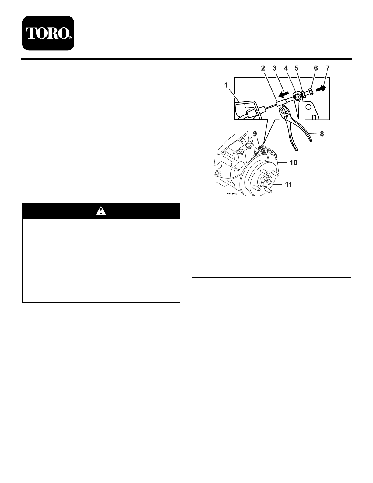
9.Holdthethreadedrodendwithatoolandloosen
thelocknutawayfromthestandardnut(Figure1).
DoNotallowthecabletoturnwhenthenutsare
beingloosened.
1.Cableanchor
2.Threadedrod8.Holdthreadedrodhere
3.Pushleverthisdirection
4.Caliperleverarm10.Caliper
5.Standardnut(shown
againstswivel)
6.Locknut
7.Pullcablethreadedrod
thisdirection
9.Swivel(pivothead)
11.Hub
10.Removeallslackfromcablebypullingonthe
threadedrodend(locknut)withamediumamount
offorce.Usingtheotherhandandngersonly,push
thecaliperleverarmtoengagethebrakepadsonthe
rotoruntiltheleverstops.Whileholdingtheleverat
thestoppedposition,pulltheslackoutofthecable
threadedendthroughtheswivel.Spinthestandard
nutagainsttheswiveltoholdthecaliperleverarm
inplace(Figure1).
Notetheorderofthestandardnutandlocknut(no
nutonthecableanchorsideoftheswivel).
11.Releasethecaliperleverandcable.Turnthewheel
hubbyhandinbothdirectionsrelativetothecaliper;
slightdragofthecaliperpadonthewheelhubis
desired.
©2009—TheToro®Company
8111LyndaleAvenueSouth
Bloomington,MN55420
Registeratwww.T oro.com.
12.Ifthereisnomovementbetweenthehubandthe
caliperthenbackoffthestandardnutoneturnfrom
theswivelandrepeatstep11(drivereleasevalves
mustbeintheopenpositiononthehydros).
OriginalInstructions(EN)
PrintedintheUSA.
AllRightsReserved
Page 2
13.Ifthehubmovesveryfreelyrelativetothecaliper,
thentightenthestandardnutoneturnagainstthe
swivelandrepeatstep11.
14.Afteradjustingthebrakesonbothsidesofthe
mower,cyclethebrakehandleaminimumofsix
timestoallowthecabletoseatintothesheathand
mountingtabs.
15.Readjustbothbrakesfollowingtheprocedurein
steps10through13.
16.Oncestep11isachieved,holdthethreadedrod
endwithatoolandtightenthelocknutagainstthe
standardnut.DoNotallowthecabletoturnwhen
thenutsaretightened(Figure1).
17.Ifabrakecomponenthasbeenremovedorreplaced,
seethestepsbelow;otherwiseproceedtostep18.
BurnishingtheBrakeProcedure:
A.Clearthecaliperareaofanyammablematerial
beforestartingtheburnishingprocess.
B.Close(runposition)thedrivewheelrelease
valves.RefertoUsingtheDriveWheelRelease
ValvessectioninOperation.
C.Applytheparkingbrake.
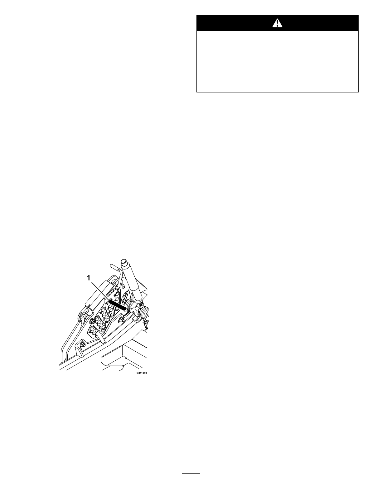
D.Installa1/2x6inch(approx.)rodorbolt
throughthe2inchheightofcuthole(see
Figure2).
Enginemustberunninganddrivewheels
mustbeturningsobrakeburnishingcanbe
performed.Contactwithmovingpartsorhot
surfacesmaycausepersonalinjury.
Keepngers,hands,andclothingclearof
rotatingcomponentsandhotsurfaces.
F.Releasetheparkbrakesothehandlerestsonthe
1/2x6inchrodorbolt.
G.Movethethrottletohighidle.
H.Movebothmotioncontrolleverstothefull
forwardpositionandholdfor15seconds.
I.Movebothmotioncontrolleverstothefull
reversepositionandholdfor15seconds.
J.Turnofftheengineandcompletelyreleasethe
parkbrakebyremovingthe1/2x6inchrodor
bolt.
K.Allowthehubstocooluntiltheyarecoolenough
tosafelytouch.
L.Open(pushposition)thedrivewheelrelease
valves.RefertoUsingtheDriveWheelRelease
ValvessectioninOperation.
M.Readjustbothbrakesfollowingtheprocedurein
steps10through13
Figure2
1.2inchheightofcutlocation
E.Startthemowerwhileintheoperatorposition.
18.Close(runposition)thedrivewheelreleasevalves.
RefertoUsingtheDriveWheelReleaseValves
sectioninOperation.
19.Installthereartiresandtorquelugnutsto90-95
ft-lb(122-129N-m).
20.Removejackstands.
2
Page 3

EnsacadoresE-ZVac
FormNo.3362-713RevA
™
TodoslosEnsacadoresEZVac
Asegúresedequeelfrenodeestacionamientoestá
ajustado.GuardeesteAnexoconsuManualdeloperador.
Ajustedelfrenode
estacionamiento
Compruebequeelfrenoestácorrectamenteajustado.
1.Coloquelamáquinasobreunasupercienivelada.
2.Desengraneelmandodecontroldelascuchillas,
pongalaspalancasdecontroldemovimientoen
posicióndebloqueo/puntomuerto,ypongaelfreno
deestacionamiento.
3.Pareelmotor,espereaquesedetengantodaslas
piezasenmovimientoyretirelallave.
4.Levantelapartetraseradelamáquinayapóyela
sobresoportesjos.
Puedeserpeligrosoconarúnicamenteen
gatosmecánicosohidráulicosparaelevar
laplataformadelcortacéspedpararealizar
tareasdemantenimientooreparación.Los
gatosmecánicosohidráulicospuedenno
proporcionarsucienteapoyo,opuedenfallar
ydejarcaerlamáquina,loquepodríaprovocar
lesiones.
Noconfíeúnicamenteengatosmecánicoso
hidráulicosparaapoyarlamáquina.Utilice
soportesjosuotromediodesustentación
equivalente.
5.Retirelasruedastraserasdelamáquina.
6.Eliminecualquiersuciedaddelazonadelosfrenos.
™
G3
Frenoizquierdoilustrado
1.Anclajedelcable7.Tiredelavarillaroscada
2.Varillaroscada
3.Empujelapalancaeneste
sentido
4.Palancadelapinza10.Pinza
5.Tuercaestándar(en
lailustración,contrael
cabezaldegiro)
6.Contratuerca
10.Eliminelaholguradelcabletirandodelextremo
roscadodelavarilla(contratuerca)conunafuerza
media.Usandolaotramanoylosdedossolamente,
empujelapalancadelapinzahastaquehagatopey
laspastillasdefrenoagarrenelrotor.Sujetandola
palancacontradeltope,tiredelextremoroscadodel
cableatravésdelpivote.Aprietelatuercaestándar
contraelpivoteparasujetarlapalancadelapinzaen
sulugar(Figura1).
Anexos
Figura1
delcableenestesentido
8.Sujeteaquílavarilla
roscada
9.Pivote
11.Cubo
7.Abralasválvulasdealiviodelasruedasmotrices
(posicióndeempujar).ConsulteUsodelasválvulas
dedesvíodelasruedasmotricesenlasecciónUso.
8.Quiteelfrenodeestacionamiento.
9.Sujeteelextremodelavarillaroscadaconuna
herramientayaojelacontratuerca,alejándoladela
tuercaestándar(Figura1).Nodejequeelcablegire
mientrasseaojanlastuercas.
©2009—TheToro®Company
8111LyndaleAvenueSouth
Bloomington,MN55420
Registresuproductoenwww.T oro.com.
Observeelordendelatuercaestándarylasdos
contratuercas(nohaytuercaenelladodelpivote
queestájuntoalanclajedelcable).
11.Sueltelapalancadelapinzayelcable.Gireelcubo
delaruedaamanoenambossentidosrespectoala
pinza;esdeseablequehayaunaligerafricciónentre
lapastillayelcubodelarueda.
Traduccióndeloriginal(ES)
ImpresoenEE.UU.
Reservadostodoslosderechos
Page 4

12.Sinohaymovimientoentreelcuboylapinza,aoje
latuercaestándarunavueltayrepitaelpaso11(las
válvulasdedesvíodelastransmisionesdebenestar
enlaposicióndeabierto).
13.Sieldelcubosemuevemuylibrementerespectoa
lapinza,aprietelastuercasdelasruedasunavuelta
contraelpivoteyrepitaelpaso11.
14.Despuésdeajustarlosfrenosenambosladosdel
cortacésped,accionelamanetadefrenounmínimo
deseisvecesparaqueelcableseasienteenlafunda
ylaspestañasdemontaje.
15.Vuelvaaajustarambosfrenossiguiendoel
procedimientodelospasos10a13.
E.Arranqueelcortacéspeddesdelaposicióndel
operador.
Elmotordebeestarenmarchaylasruedas
motricesdebenestargirandopararealizarel
bruñido.Elcontactoconpiezasenmovimiento
osuperciescalientespuedecausarlesiones
personales.
Mantengaalejadosdeloscomponentes
rotativosydelasuperciescalienteslosdedos,
lasmanosylaropa.
16.Unavezlogradoloindicadoenelpaso11,sujeteel
extremodelavarillaroscadaconunaherramientay
aprietalacontratuercacontralatuercaestándar.No
dejequeelcablegiremientrasseaprietanlastuercas
(Figura1).
17.Siseharetiradoocambiadocualquiercomponente
delfreno,consultelospasossiguientes;delo
contrariovayaalpaso18.
Procedimientodebruñidodelfreno:
A.Eliminecualquiermaterialinamabledelazona
delapinzaantesdeiniciarelprocedimientode
bruñido.
B.Cierrelasválvulasdealiviodelasruedasmotrices
(posicióndemarcha).ConsulteUsodelas
válvulasdedesvíodelasruedasmotricesenla
secciónUso.
C.Pongaelfrenodeestacionamiento.
D.Instaleunavarillaounpernode1/2x6pulgadas
(aprox.)poreltaladrodealturadecortede51
mm(verFigura2).
F.Quiteelfrenodeestacionamientodemodoque
lapalancadescansesobrelavarillaoelpernode
1/2x6pulgadas.
G.Pongaelaceleradorenralentíalto.
H.Muevaambaspalancasdecontroldemovimiento
alaposiciónmásadelantadaposibleysujételas
enesaposicióndurante15segundos.
I.Muevaambaspalancasdecontroldemovimiento
alaposiciónmásatrasadaposibleysujételasen
esaposicióndurante15segundos.
J.Pareelmotoryquitecompletamenteelfrenode
estacionamientoretirandolavarillaoelpernode
1/2x6pulgadas.
K.Dejequeseenfríenloscuboshastaquesehayan
enfriadolosucienteparapoderlostocarsin
peligrodequemarse.
L.Abralasválvulasdealiviodelasruedasmotrices
(posicióndeempujar).ConsulteUsodelas
válvulasdedesvíodelasruedasmotricesenla
secciónUso.
Figura2
1.Posicióndealturadecortede51mm
M.Vuelvaaajustarambosfrenossiguiendoel
procedimientodelospasos10a13.
18.Cierrelasválvulasdealiviodelasruedasmotrices
(posicióndemarcha).ConsulteUsodelasválvulas
dedesvíodelasruedasmotricesenlasecciónUso.
19.Instalelosneumáticostraserosyaprietelastuercasa
122–129Nm.
20.Retirelossoportes.
2
 Loading...