

Page 1
FormNo.3395-248RevB
48inand52inE-ZVacTwin
BaggingSystemor60inand72in
E-ZVacTripleBaggingSystem
ZMasterG3Mower
ModelNo.78562—SerialNo.290000001andUp
ModelNo.78563—SerialNo.290000001andUp
ModelNo.78564—SerialNo.290000001andUp
Registeratwww.T oro.com.
OriginalInstructions(EN)
*3395-248*B
Page 2
ThisproductcomplieswithallrelevantEuropeandirectives.
Fordetails,pleaseseetheDeclarationofIncorporation(DOI)
atthebackofthispublication.
Introduction
Readthisinformationcarefullytolearnhowtooperateand
maintainyourproductproperlyandtoavoidinjuryand
productdamage.Youareresponsibleforoperatingthe
productproperlyandsafely.
YoumaycontactTorodirectlyatwww .Toro.comforproduct
safetyandoperationtrainingmaterials,accessoryinformation,
helpndingadealer,ortoregisteryourproduct.
Wheneveryouneedservice,genuineT oroparts,oradditional
information,contactanAuthorizedServiceDealerorToro
CustomerServiceandhavethemodelandserialnumbersof
yourproductready .Figure1,Figure2andFigure3identies
thelocationofthemodelandserialnumbersontheproduct.
Writethenumbersinthespaceprovided.
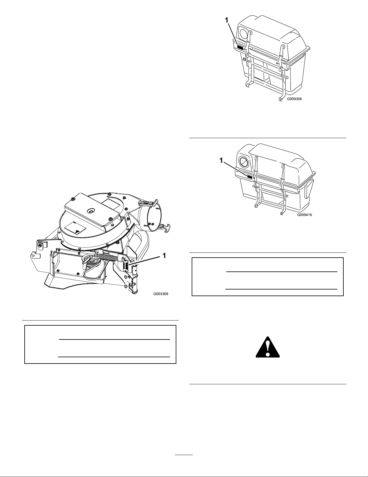
Figure2
48-and52-inchbaggerserialnumber
1.Baggermodelandserialnumberlocation
Figure1
1.Blowermodelandserialnumberlocation
ModelNo.
SerialNo.
Figure3
60-and72-inchbaggerserialnumber
1.Baggermodelandserialnumberlocation
ModelNo.
SerialNo.
Thismanualidentiespotentialhazardsandhassafety
messagesidentiedbythesafetyalertsymbol(Figure4),
whichsignalsahazardthatmaycauseseriousinjuryordeath
ifyoudonotfollowtherecommendedprecautions.
Figure4
1.Safetyalertsymbol
Thismanualuses2wordstohighlightinformation.
Importantcallsattentiontospecialmechanicalinformation
andNoteemphasizesgeneralinformationworthyofspecial
attention.
©2015—TheToro®Company
8111LyndaleAvenueSouth
Bloomington,MN55420
Contactusatwww.Toro.com.
2
PrintedintheUSA
AllRightsReserved
Page 3

Contents
Safety
Safety...........................................................................3
SafetyandInstructionalDecals.................................4
Setup............................................................................5
1PreparingtheMachine...........................................6
2InstallingtheSideBumpers....................................6
3InstallingtheBaggerMountingBrackets...................7
4InstallingtheHoodAssemblyandBags....................7
5InstallingtheMuferDeector...............................9
6RoutingtheBlowerBeltintotheBlower
Assembly...........................................................10
7InstallingtheBlowerAssembly..............................10
8InstallingtheDischargeTubes...............................12
9InstallingtheBeltCover........................................16
10InstallingtheWeights..........................................17
11InstallingtheBumpers........................................19
12AdjustingtheParkingBrake.................................19
13CheckingtheTirePressure..................................20
Operation....................................................................20
PositioningtheAdjustableBafe..............................21
EmptyingtheGrassBags.........................................21
ClearingObstructionsfromtheBagger
System..............................................................21
RemovingtheBagger..............................................22
UsingtheGrassDeector.......................................22
TransportingtheMachine........................................22
OperatingTips......................................................22
Maintenance.................................................................24
RecommendedMaintenanceSchedule(s)......................24
CleaningtheHoodScreen.......................................24
CleaningtheBaggerandBags...................................24
InspectingtheBlowerBelt.......................................24
ReplacingtheBlowerBeltfor60-and72-inch
Machines...........................................................24
ReplacingtheBlowerBeltfor48-and52-inch
Machines...........................................................25
CheckingandAdjustingtheBlowerLatch..................25
GreasingtheIdlerArm...........................................26
InspectingtheBagger.............................................26
InspectingtheMowerBlades...................................26
InstallingtheMowerBlades.....................................26
ReplacingtheGrassDeector..................................26
Storage........................................................................27
Troubleshooting...........................................................28
ThefollowinglistcontainssafetyinformationspecictoToro
productsandothersafetyinformationyoumustknow .
•Becomefamiliarwiththesafeoperationoftheequipment,
withtheoperatorcontrols,andsafetysigns.
•Useextracarewithgrasscatchersorotherattachments.
Thesecanchangetheoperatingcharacteristicsandthe
stabilityofthemachine.
•Followthemanufacturer'srecommendationsforadding
orremovingwheelweightsorcounterweightstoimprove
stability.
•Donotuseagrasscatcheronsteepslopes.Aheavy
grasscatchercouldcauselossofcontroloroverturnthe
machine.
•Slowdownanduseextracareonhillsides.Besureto
travelintherecommendeddirectiononhillsides.Turf
conditionscanaffectthestabilityofthemachine.Use
extremecautionwhileoperatingneardrop-offs.
•Keepallmovementonslopesslowandgradual.Donot
makesuddenchangesinspeed,directionsorturning.
•Thegrasscatchercanobstructtheviewtotherear.Use
extracarewhenoperatinginreverse.
•Usecarewhenloadingorunloadingthemachineintoa
trailerortruck.
•Neveroperatewiththedischargedeectorraised,
removedoraltered,unlessusingagrasscatcher.
•Keephandsandfeetawayfrommovingparts.Donot
makeadjustmentswiththeenginerunning.
•Stoponlevelground,disengagedrives,chockorblock
wheels,shutoffenginebeforeleavingtheoperator's
positionforanyreasonincludingemptyingthegrass
catcheroruncloggingthechute.
•Ifyouremovethegrasscatcher,besuretoinstallany
dischargedeectororguardthatmighthavebeen
removedtoinstallthegrasscatcher.Donotoperatethe
machinewithouteithertheentiregrasscatcherorthe
grassdeectorinplace.
•Stoptheenginebeforeremovingthegrasscatcheror
uncloggingthechute.
•Donotleavegrassingrasscatcherforextendedperiods
oftime.
•Grasscatchercomponentsaresubjecttowear,damage
anddeterioration,whichcouldexposemovingpartsor
allowobjectstobethrown.Frequentlycheckcomponents
andreplacewithmanufacturer'srecommendedparts,
whennecessary.
3
Page 4
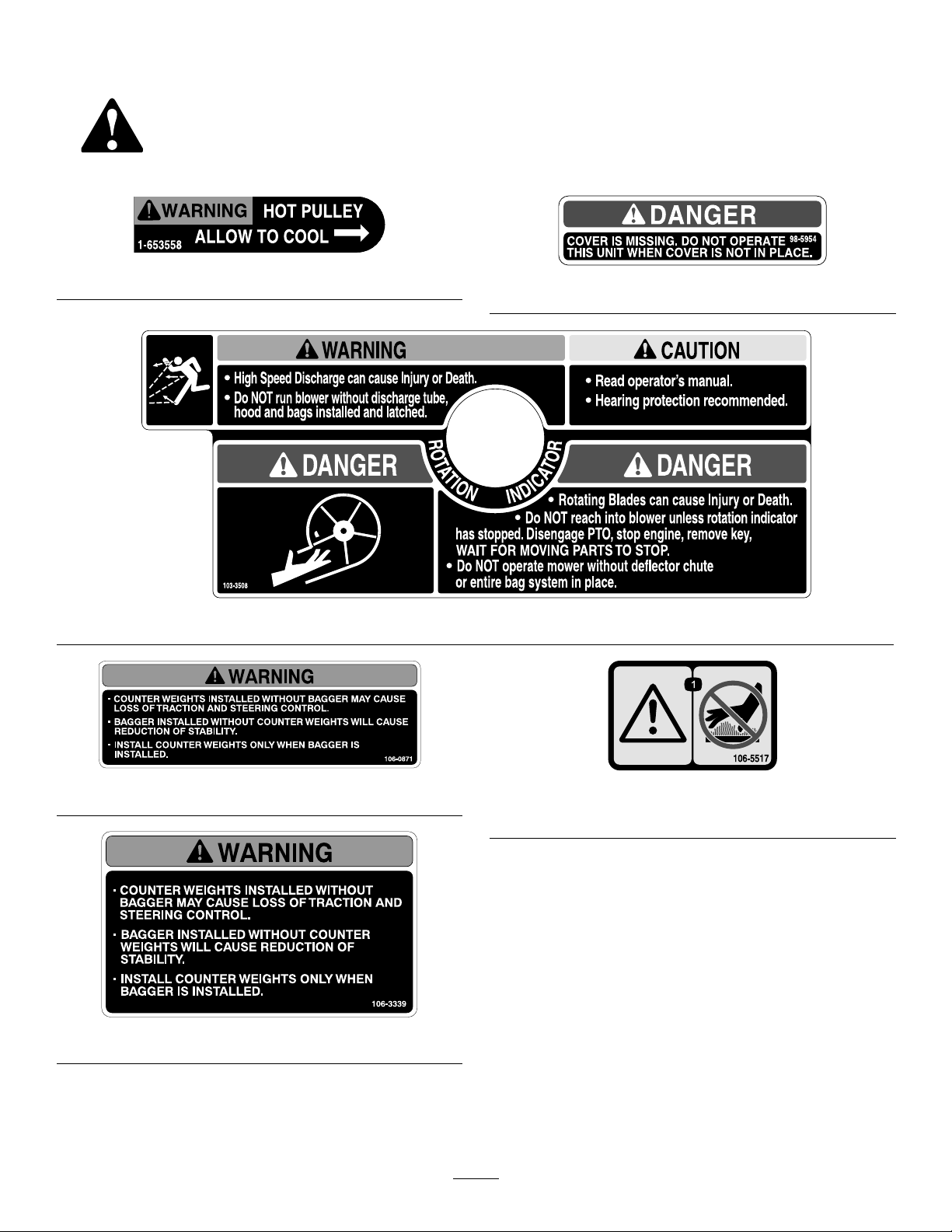
SafetyandInstructionalDecals
Safetydecalsandinstructionsareeasilyvisibletotheoperatorandarelocatednearanyareaofpotential
danger.Replaceanydecalthatisdamagedorlost.
1-653558
103-3508
98-5954
106-0871
1.Warning—donottouchthehotsurface.
106-3339
4
106-5517
Page 5

Setup
LooseParts
Usethechartbelowtoverifythatallpartshavebeenshipped.
ProcedureDescription
1
2
3
4
5
6
7
8
Nopartsrequired
Leftbumper
Rightbumper1
Carriagebolt(3/8x1-1/4inches)
Flangenut(3/8inch)
Uppermountingbracket1
Lowermountingbracket1
Carriagebolt(3/8x1-1/4inches)
Carriagebolt(1/2x2–1/2inches)
Flangenut(3/8inch)
Flangenut(1/2inch)
Hoodassembly1
Bag(48-inchand52-inchdecks)
Bag(60-inchand72-inchdecks)
Pinandhairpin-cotterassembly2
Muferdeector
Flangenut(3/8inch)
Carriagebolt(3/8x1-1/4inches)
Blowerbelt(fromBlowerandDriveKit)
Blowerassembly(fromtheBlowerand
DriveKit)
Spring(fromtheBlowerandDriveKit)
Uppertube1
Lowertube1
Bolt(#10x3/4inches)
Locknut(#10)
Washer(7/32inch)
Qty.
Use
–
1
2
6
4
2
4
2
2
3
1
2
2
1
1
1
3
3
3
Preparethemachine.
Installthesidebumpers.
Installthebaggermountingbrackets.
Installthehoodassemblyandbags.
Installthemuferdeector.
Routetheblowerbeltintotheblower
assembly.
Installtheblowerassembly .
Installthedischargetubes.
9
10
Beltcover(fromBlowerandDriveKit)
Casterweight(ifneeded)
Clevispin
Hairpincotter2
Lockwasher(3/8inch)
Weight-mountbracket1
Bolt(3/8x1-1/2inches)
Flatwasher(3/8inch)
Carriagebolt(5/16x3/4inch)
Flangenut(5/16inch)
Frontweight(48-inch,52-inch,and
60-inchdecks)
Frontweight(72-inchdecks)
5
1Installthebeltcover.
2
2
6
6
6
3
3
3
1
Installtheweights.
Page 6
ProcedureDescription
11
Bumper2
Spacer
Locknut(5/16inch)
Qty.
Use
2
2
Installthebumpers(formachineswith
MyRide™suspensionsystem).
12
13
Note:Determinetheleftandrightsidesofthemachinefromthenormaloperatingposition.
1
Nopartsrequired
Nopartsrequired
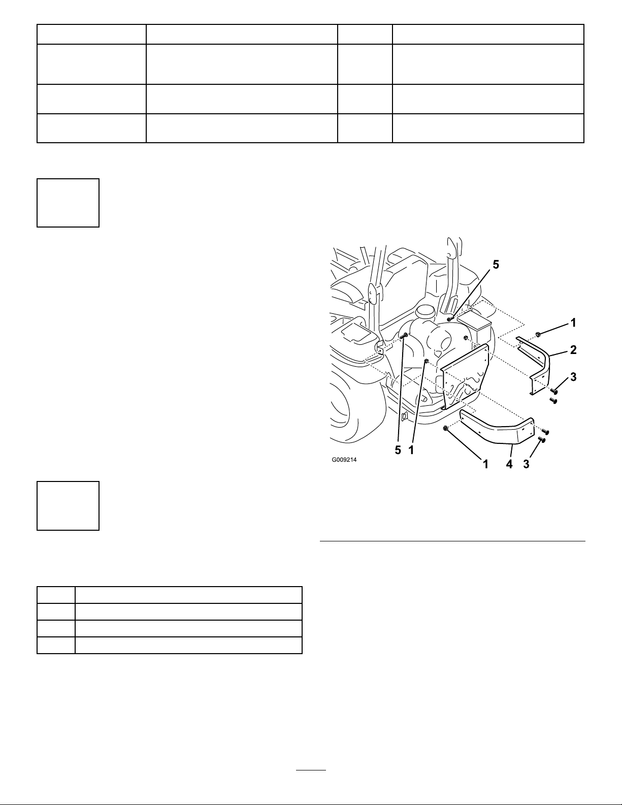
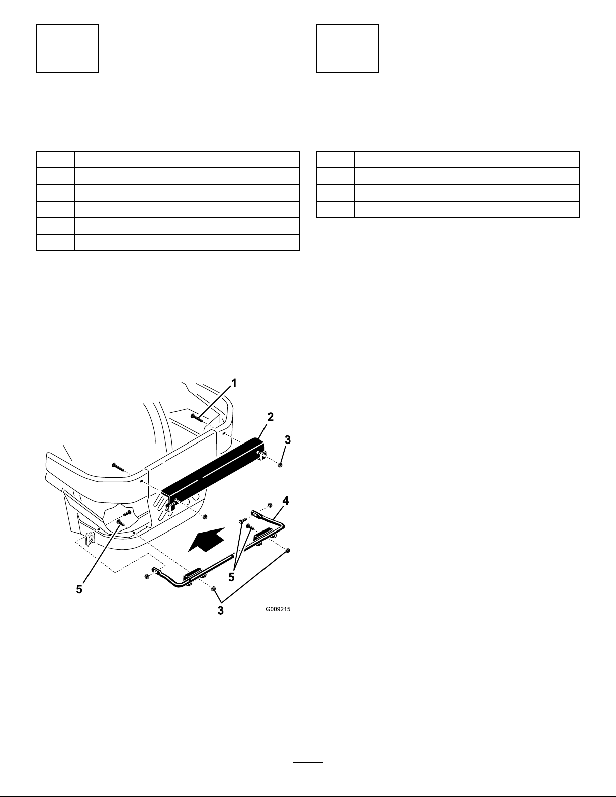
2.Installthenewleftandrightsidebumperswith2
carriagebolts(3/8x1-1/4inches),4previously
removedcarriagebolts,and6angenuts(3/8inch)as
showninFigure5.
PreparingtheMachine
NoPartsRequired
Procedure
Performthefollowingproceduretopreparethemachinefor
attachingtheblowerandnishingkit.
1.DisengagethePTO,movethemotion-controllevers
totheNEUTRAL-LOCKEDpositionandsettheparking
brake.
2.Stoptheengine,removethekey,andwaitforallmoving
partstostopbeforeleavingtheoperatingposition.
3.Repairallbentordamagedareasofmachinedeckand
replaceanymissingparts.
4.Cleanthemachineofanydebrisonthemachinedeck
orrearpartofthemachinetoeaseinstallation.
–
–
Adjusttheparkingbrake.
Checkthetirepressure.
Figure5
2
InstallingtheSideBumpers
Partsneededforthisprocedure:
1
Leftbumper
1Rightbumper
2
Carriagebolt(3/8x1-1/4inches)
6
Flangenut(3/8inch)
Procedure
1.Removethenutsandboltsholdingthesidebumpers
tothemachine(Figure5).
Note:Discardallnutsandonlythe1boltremoved
fromeachside.
1.Flangenut(3/8inch)4.Leftbumper
2.Rightbumper
3.Useexistingbolts
6
5.Bolt(3/8x1-1/4inches)
Page 7
3
4
InstallingtheBaggerMounting Brackets
Partsneededforthisprocedure:
1Uppermountingbracket
1Lowermountingbracket
4
Carriagebolt(3/8x1-1/4inches)
2
Carriagebolt(1/2x2–1/2inches)
4
Flangenut(3/8inch)
2
Flangenut(1/2inch)
Procedure
1.Installthelowermountingbrackettothemachine
framewith4carriagebolts(3/8x1-1/4inches)and
4angenuts(3/8inch)asshowninFigure6.
2.Installtheuppermountingbrackettotheleftandright
sidebumperswith2carriagebolts(1/2x2-1/2inches)
and2angenuts(1/2inch)asshowninFigure6.
InstallingtheHoodAssembly andBags
Partsneededforthisprocedure:
1Hoodassembly
2
Bag(48-inchand52-inchdecks)
3
Bag(60-inchand72-inchdecks)
2Pinandhairpin-cotterassembly
Procedure
1.Positionthehoodassemblyonitsback.
2.Slidehooksontothelowermountingbracket(Figure
7).
3.Rotatethehoodassemblyuponthelowerbagger
mountingbracket(Figure7).
4.Aligntheholeinthebaggerwiththeuppermounting
bracket(Figure7).
5.Installthepinandsecureitwiththehairpincotteron
bothsides(Figure7).
Figure6
1.Carriagebolt(1/2x2-1/2
inches)
2.Uppermountingbracket
3.Flangenut(1/2inch)6.Flangenut(3/8inch)
4.Lowermountingbracket
5.Carriagebolt(3/8x1-1/4
inches)
7
Page 8
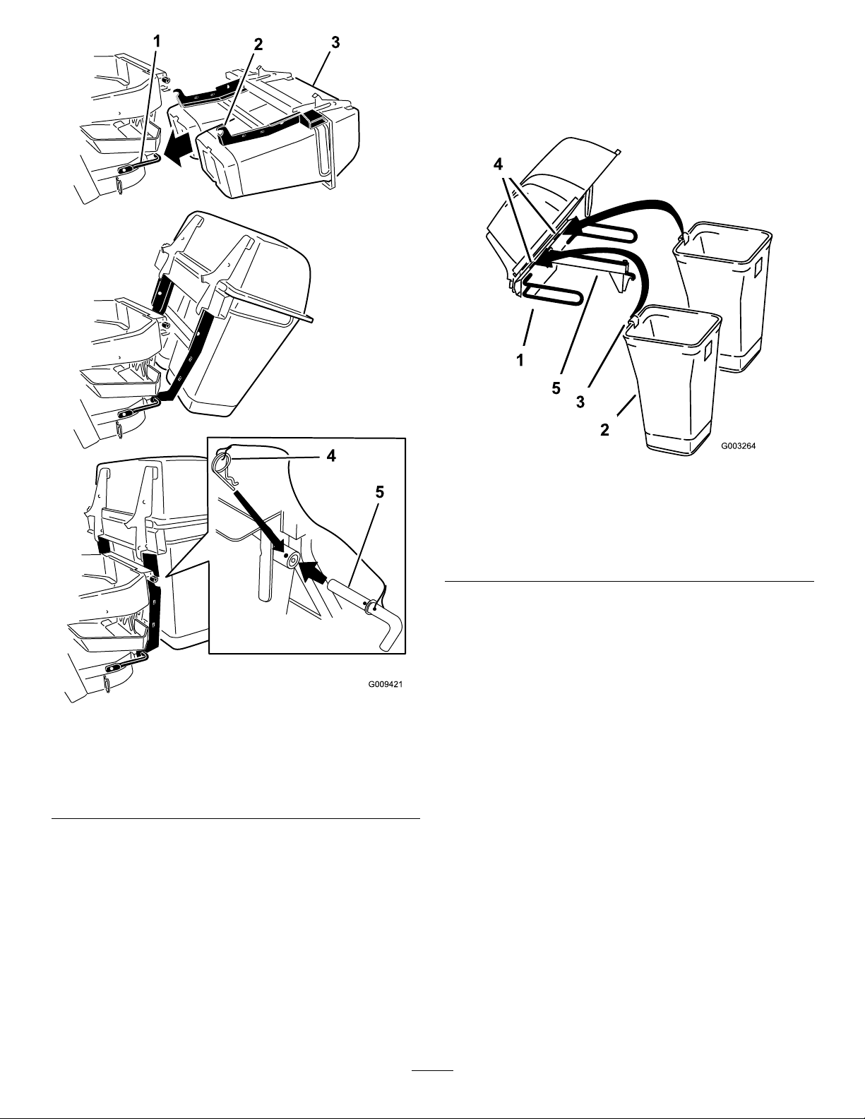
6.Installthebagtabintothenotchinthehoodassembly
(Figure8orFigure9).
Note:Dothisforallthebags.
Note:Thebagswillrestonthebaggerframe.
Figure7
1.Lowermountingbracket4.Hairpincotterconnected
tolanyard
2.Hook5.Pinconnectedtolanyard
3.Hoodassembly
Figure8
Twinbaggershown
1.Hoodassembly4.Notch
2.Bag
3.Bagtab
5.Baggerframe
8
Page 9
Triplebaggershown
Figure9
Figure11
Triplebaggershown
1.Hoodassembly4.Notch
2.Bag
3.Bagtab
5.Baggerframe
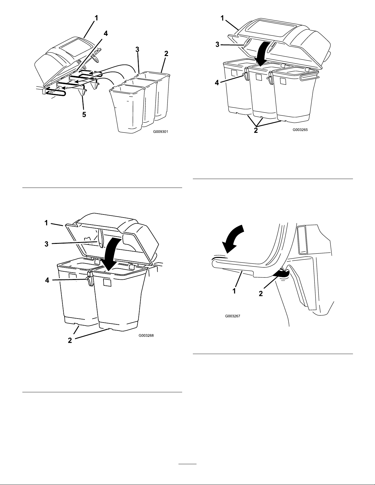
7.Lowerthebaggerhoodoverthebags(Figure10or
Figure11).
1.Hood3.Baggerlatch
2.Bag4.Latchhook
8.Positionthebaggerlatchunderthelatchhook(Figure
12).
9.Pushdownonbaggerlatchuntilitlocksintoplace
(Figure12).
Figure12
Figure10
Twinbaggershown
1.Hood3.Baggerlatch
2.Bag4.Latchhook
1.Baggerlatch2.Latchhook
9
Page 10
5
InstallingtheMuferDeector
Partsneededforthisprocedure:
1
Muferdeector
2
Flangenut(3/8inch)
2
Carriagebolt(3/8x1-1/4inches)
Procedure
Installthemuferdeectortothesideofthebaggerframe
(Figure13).
Note:Ensurethemuferdeectorispositionedoverthe
tailpipeofthemufer.
Figure13
1.Muferdeector3.Carriagebolt(3/8x1-1/4
inches)
2.Flangenut(3/8inch)
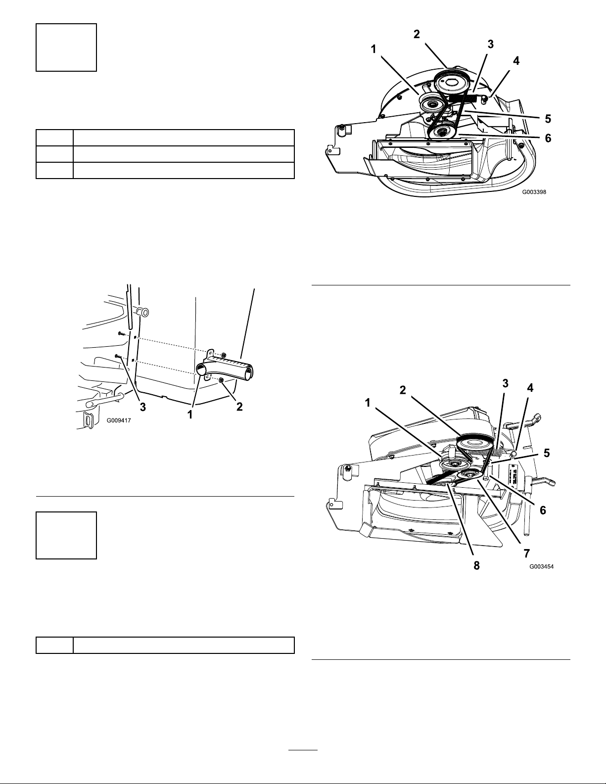
Figure14
Blowerfor60-and72-inchmachines
1.Idlerpulley
2.Machinedeckpulley5.Belt
3.Spring
2.For48-and52-inchmachines,loosenthebelt-guide
bolt(Figure15).
3.Installthebeltaroundtheblowerpulleyandxed-idler
pulley(Figure15).
4.Tightenthebelt-guidebolt.
4.Springpeg
6.Blowerpulley
6
RoutingtheBlowerBeltinto theBlowerAssembly
Partsneededforthisprocedure:
1
Blowerbelt(fromBlowerandDriveKit)
Procedure
1.For60-and72-inchmachinedecks,installthebelt
aroundtheblowerpulley(Figure14).
Figure15
1.Idlerpulley5.Belt
2.Machinedeckpulley6.Belt-guidebolt
3.Spring
4.Springpeg
10
7.Fixed-idlerpulley
8.Blowerpulley
Page 11

7
InstallingtheBlowerAssembly
Partsneededforthisprocedure:
1
Blowerassembly(fromtheBlowerandDriveKit)
1
Spring(fromtheBlowerandDriveKit)
Procedure
WARNING
Anuncovereddischargeopeningcouldallowthe
lawnmowertothrowobjectsatyouorbystanders,
resultinginseriousinjury.Also,contactwiththe
bladecouldoccur.
•Neveroperatethelawnmowerunlessyouinstall
acoverplate,amulchplate,oragrasschuteand
catcher.
•Makesurethatthegrassdeectorisinstalled
whenthegrasschuteandcatcherareremoved.
1.Removethesidedischargechutefromthemowerdeck
(Figure16).
Note:Saveallthehardwareandthesidedischarge
chute.Installthesidedischargechutewhenthebagger
andblowerareremoved.
Figure17
48-and52-inchmowerdeckshown
1.Blowerassembly3.Pivothole
2.Mowerdeck4.Blower-assemblypeg
Figure18
60-and72-inchmowerdeckshown
1.Blowerassembly3.Pivothole
2.Mowerdeck4.Blower-assemblypeg
Figure16
1.Bolt
2.Spacer6.Grassdeector
3.Locknut
4.Spring8.J–hookendofspring
2.Slidetheblower-assemblypegintothepivothole
(Figure17orFigure18).
5.Springinstalled
7.Lendofspring(place
behindthedeckedge
beforeinstallingthebolt)
11
Page 12

3.Closetheblowerassemblytoseeifthelatchesare
adjustedcorrectly.
5.Pullthespring-loadedidlerpulleybackandroutethe
beltaroundthemower-deckpulley .
Note:Loosenortightentheboltsothelatchesrmly
holdtheblowerassemblyagainstthemowerdeck,but
canbereleasedbyhand(Figure19).
Figure19
1.Latch3.Blowerassembly
2.Bolt
4.InstallthespringasshowninFigure20.
Note:Makesurethatthehooksareinthecorrect
position.
Note:Ensurethatthebeltisroutedaroundtheblower
pulleyscorrectly(Figure21).
Figure21
1.Mower-deckpulley3.Blower
2.Spring-loadedidlerpulley
1.Spring-loadedidlerpulley
2.Short-hookend
Figure20
3.Long-hookend
8
InstallingtheDischargeTubes
Partsneededforthisprocedure:
1Uppertube
1Lowertube
3
Bolt(#10x3/4inches)
3
Locknut(#10)
3
Washer(7/32inch)
Procedure
Important:Makesurethatthemowerdeckisin
thelowestheight-of-cutpositionwhileinstallingthe
dischargetubes.
Note:Remembertoreplacethegrassdeectorwhenthe
baggerisremovedfromthemachine.RefertoReplacingthe
GrassDeector(page26).
1.DisengagethePTOandsettheparkingbrake.
2.Stoptheengine,removethekey,andwaitforallmoving
partstostopbeforeleavingtheoperatingposition.
3.Lowerthemachinedecktothelowestheight-of-cut
position.
4.Removethebagsforviewingthetubeunderthehood.
12
Page 13

5.Installtheuppertubeintothebaggeropeningandpull
itbackoutsothattherubbersealisprotrudingout
(Figure22orFigure23).
Figure22
Twinbaggershown
1.Uppertube3.Baggerhood
2.Baggeropening
6.Withthehoodinthedownposition,measurethe
distancethetubeisinsidethehood.
Measurefromthehoodplatetotheedgeofthetubeas
showninFigure24.
Note:Thisdistanceneedstobe19mm(3/4inch).
Figure23
Triplebaggershown
1.Uppertube3.Baggerhood
2.Baggeropening
1.Hoodplate
2.Uppertube
3.Hoodinthedownposition
Figure24
4.19mm(3/4inch)
5.Edgeoftube
13
Page 14

7.Oncethe19mm(3/4inch)measurementhasbeen
achieved,marktheuppertubeontheoutsidewhere
therubbersealprotrudesout(Figure25).
Note:Thisismarkedtoensurethecorrectposition
fortheuppertubewhendrillingtheholesand
connectingtheupperandlowertubes.
Note:Therubbersealmustprotrudeoutfromthe
baggerhood.
9.Slidethelowertubeontothebootandlatchthem
together(Figure27orFigure28).
Note:Thereisalatchonthetopandbottomofthe
blowerhousing.
Figure25
1.Uppertube3.Baggerhood
2.Rubbersealprotrudingout4.Markhereagainstthe
rubberseal
8.Installthelowertubeintotheuppertube(Figure26).
1.Blowerassembly
2.Lowertube
Figure27
Twinbaggershown
3.Latch(twinbaggershown)
Figure26
1.Lowertube2.Uppertube
14
Page 15

12.Usingthe3holesorindentationsintheuppertubeasa
template,drill3holes(7/32inchdiameter)wherethe
upperandlowertubesjointogether(Figure29).
Figure28
Triplebaggershown
1.Blowerassembly
2.Lowertube
3.Latch(triplebagger
shown)
10.Makesurethatthemachinedeckisinthelowest
height-of-cutposition.
11.ChecktomakesurethatthemarkfromFigure25is
stillinplace.
Figure29
1.Baggerhood4.Lowertube
2.Uppertube5.Blowerassembly
3.Drill7/32inchdiameter
holeshere(useuppertube
asatemplate)
13.Removethelowertubefromtheblower.
15
Page 16

14.Jointheupperandlowertubeswith3bolts(#10x
1
2
G009305
3/4inches),3atwashers(7/32inch),and3locknuts
(#10)asshowninFigure30.
9
InstallingtheBeltCover
Partsneededforthisprocedure:
1
Beltcover(fromBlowerandDriveKit)
Procedure
1.Lowerthemowerdecktothelowestheight-of-cut
position.
2.Installthenewbeltcoversothatthenotchesonboth
sidesgooverthebelt-coversupportsandsecurethe
latch(Figure31orFigure32).
Figure30
1.Lowertube
2.Uppertube
3.Flatwasher(7/32inch)
15.Installthelowertubeontotheblowerhousingand
secureitwiththelatches.
16.Installthebagsontothebagger.
4.Locknut(#10)
5.Bolt(#10x3/4inches)
Figure31
48-and52-inchbaggershown
1.Beltcover3.Notch
2.Belt-coversupport
16
Page 17

G009303
1
2
Thefollowingtableshowswhatweightsareusedwhena
baggerisinstalled.
Figure32
60-and72-inchbaggershown
1.Beltcover3.Notch
2.Belt-coversupport
48-inchmachine
deckwithbagger
52-inchmachine
deckwithbagger
60-inchmachine
deckwithbagger
72-inchmachine
deckwithbagger
Frontweights
used
30
30
32
12
Casterweights
used
1.Installcasterweightsonthefrontcasterswithaclevis
pinandahairpincotter(Figure33).
2.Installthenutontoeachtapboltandinstallthetap
boltsintoeachweight(Figure33).
3.Tightenthetapboltsoittouchestheframeandthen
tightenthejamnutagainsttheweight.
10
InstallingtheWeights
Partsneededforthisprocedure:
2
Casterweight(ifneeded)
2
Clevispin
2Hairpincotter
6
Lockwasher(3/8inch)
1Weight-mountbracket
6
Bolt(3/8x1-1/2inches)
6
Flatwasher(3/8inch)
3
Carriagebolt(5/16x3/4inch)
3
Flangenut(5/16inch)
3
Frontweight(48-inch,52-inch,and60-inchdecks)
1
Frontweight(72-inchdecks)
Procedure
TocomplywithANSI/OPEIB71.4-2012Standard,add
weightstothemachine.
Figure33
1.Tapbolt(3/8x1-1/2
inches)
2.Nut(3/8inch)5.Clevispin
3.Casterweight
4.Hairpincotter
6.Installthetapboltagainst
theframeandtightenthe
nut.
CAUTION
Thebaggeraddsalotofweighttotherearofthe
machineandmaycauseanunstablecondition
whichcouldresultinalossofcontrol.
17
Page 18

4.Installtheweight-mountbracketunderthefootrest
with2carriagebolts(5/16x3/4inch)and2ange
nuts(5/16inch)asshowninFigure34).
Figure34
1.Carriagebolt(5/16x3/4
inch)
2.Weight-mountbracket
3.Flangenut(5/16inch)
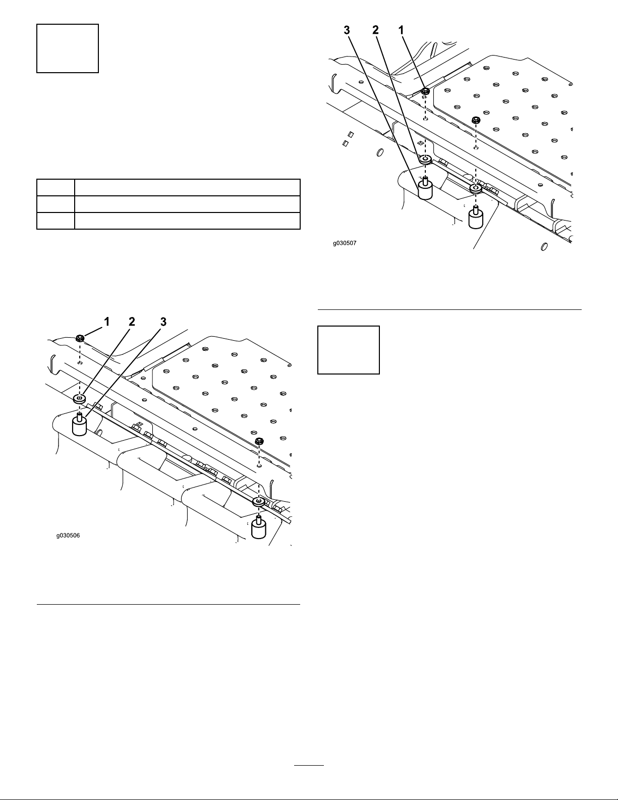
5.Installthefrontweightsontopofthefootrest(Figure
35).
Figure36
1.Weight-mountbracket
2.Flatwasher(3/8inch)4.Bolt(3/8x1inch)
3.Lockwasher(3/8inch)
6.Securethefrontweightsontopofthefootrestandto
theweight-mountbracketwith6bolts(3/8x1inch),6
lockwashers(3/8inch),3angenuts(3/8inch)and6
atwashers(3/8inch)asshowninFigure35.
Figure35
1.Frontweight
2.Flatwasher(3/8inch)5.Holeinfootrest
3.Lockwasher(3/8inch)6.Flangenut(3/8inch)
4.Bolt(3/8x1inch)
18
Page 19
11
InstallingtheBumpers
MachineswithMyRide™Suspension
System
Partsneededforthisprocedure:
2Bumper
2
Spacer
2
Locknut(5/16inch)
Procedure
For48-inch,52-inch,and60-inchdecks,installthe
bumperstothe2outsideholesofthetoeboard(Figure37).
Figure38
1.Locknut3.Bumper
2.Spacer
12
AdjustingtheParkingBrake
NoPartsRequired
Procedure
Checktomakesuretheparkingbrakeisadjustedproperly.
RefertoyourOperator’ sManualforthecorrectprocedure.
Figure37
1.Locknut3.Bumper
2.Spacer
For72-inchdecks,installthebumperstothe2insideholes
ofthetoeboard(Figure38).
19
Page 20

Operation
13
CheckingtheTirePressure
NoPartsRequired
Procedure
Note:Increasethetirepressureduetotheadditionalweight.
Checkandincreasetheairpressureinthefrontcasterwheels
andreartires(Figure39).
Airpressureinthereartires:138kPa(20psi)
Airpressureinthefrontcasterwheels:172kPa(25psi)
Note:Determinetheleftandrightsidesofthemachine
fromthenormaloperatingposition.
Important:Settheparkingbrakewhenleavingthe
machineunattended,evenifjustforafewminutes.
WARNING
Toavoidpersonalinjury,followtheseprocedures:
•Becomefamiliarwithalloperatingandsafety
instructionsinthe
machinebeforeusingthisattachment.
•Neverremovethebaggerorbaggertubeswhile
theengineisrunning.
•Alwaysshuttheengineoffandwaitforall
movingpartstostopbeforeclearingan
obstructionfromthebaggingsystem.
•Neverdomaintenanceorrepairswhilethe
engineisrunning.
•Settheparkingbrake.
Operator's Man ual
foryour
Figure39
WARNING
Withoutthegrassdeector,baggertubesor
completebaggerassemblymountedinplace,you
andothersareexposedtobladecontactandthrown
debris.Contactwiththerotatingmowerblade(s)
andthrowndebriswillcauseinjuryordeath.
•Alwaysinstallthegrassdeectorwhenremoving
thebaggerandchangingtosidedischarge
mode.
•Ifthegrassdeectoriseverdamaged,replaceit
immediately.Thegrassdeectorroutesmaterial
downtowardtheturf.
•Neverputyourhandsorfeetunderthemower
deck.
•Nevertrytoclearthedischargeareaormower
bladesunlessyoumovethepowertake-off
(PTO)tooffandrotatetheignitionkeytooff.
Alsoremovethekeyandpullthewireoffthe
sparkplug(s).
•Turnofftheenginebeforeuncloggingthe
dischargechute.
20
Page 21

CAUTION
Childrenorbystandersmaybeinjuredifthey
moveorattempttooperatethemachinewhileitis
unattended.
Alwaysremovetheignitionkeyandsettheparking
brakewhenleavingthemachineunattended,even
ifjustforafewminutes.
PositioningtheAdjustable
Bafe
AdjustthebafetopositionB(middleposition)forbagging.
RefertotheOperatorManualforthemachine.
Figure41
1.Bag2.Bottomhandle
6.Repeatfortheotherbag.
7.Installthebagtabintothenotchinthebaggersupport
frame.
Figure40
EmptyingtheGrassBags
Grassbagsareheavywhenfull.Becarefulwhenliftingor
handlingagrassbagthatisfull.
1.DisengagethePTO,settheparkingbrake,andchock
orblockthetiresifonaslope.
2.Unlatchthebaggerlatch.
3.Openthebaggerhood.
4.Compressthedebrisintothebags.Withbothhands,
liftuponthebagandunhookitfromthebagger
bracket.
5.Grabthehandleonthebottomofthebagandtipit
overtoemptythebag(Figure41).
Note:Dothisforbothbags.
8.Lowerthebaggerhoodoverthebags.
9.Latchthebaggerhood.
ClearingObstructionsfrom theBaggerSystem
WARNING
Whenthebaggerisinoperation,theblowercanbe
rotatingandcutofforinjurehands.
•Beforeadjusting,cleaning,repairingand
inspectingtheblower,andbeforeunclogging
thechute,turnofftheengineandwaitforall
movingpartstostop.Removethekey .
•Useastick,notyourhands,toremovean
obstructionfromtheblowerandtube.
•Keepface,hands,feet,andanyotherpartof
yourbodyorclothingawayfromconcealed,
moving,orrotatingparts.
1.DisengagethePTOandsettheparkingbrake.
2.Turnofftheengine,removethekey,andwaitforall
movingpartstostopbeforeleavingtheoperating
position.
3.Emptythebags.
4.Unlatchthelowertube.
5.Removethetubesfromthebagger.
21
Page 22

6.Useastickorsimilarobject,notyourhands,toremove
andcleartheobstructionfromthetubeassembly .
UsingtheGrassDeector
Note:Inmostcases,thedebriscanbeshakenoutof
thetubes.
7.Iftheblowerassemblyisplugged,unlatchthebagger
blowerassembly,removethebelt,andswingitopen.
8.Useastickorsimilarobject,notyourhands,toremove
andcleartheobstructionfromtheblowerassembly.
9.Afteryouremovetheobstruction,installthecomplete
baggersystemandresumeoperation.
RemovingtheBagger
WARNING
Componentsaroundenginewillbehotifthe
machinehasbeenrunning.Touchinghot
componentscancauseburns.
•Donottouchenginecomponentswhenhot.
•Allowenginetocoolbeforeremovingthebagger.
1.DisengagethePTO,settheparkingbrake,andchock
orblockthetires.
2.Turnofftheengine,removethekey,andwaitforall
movingpartstostopbeforeleavingtheoperating
position.
3.Unlatchthelowertubefromtheblowerandremove
thetubefromtheblowerassembly.
4.Removethetubefromthebaggerhood.
DANGER
Withoutthegrassdeector,dischargecover,or
completegrasscatcherassemblymountedin
place,youandothersareexposedtobladecontact
andthrowndebris.Contactwithrotatingmower
blade(s)andthrowndebriswillcauseinjuryor
death.
•Alwaysinstallthegrassdeectorwhenremoving
thebaggerandchangingtosidedischarge
mode.
•Ifthegrassdeectoriseverdamaged,replaceit
immediately.Thegrassdeectorroutesmaterial
downtowardtheturf.
•Neverputyourhandsorfeetunderthemower
deck.
•Nevertrytoclearthedischargeareaormower
bladesunlessyoumovethepowertake-off
(PTO)totheOFFposition,rotatetheignition
keytooffandremovethekey.
•Neveruseyourhandstoclearthedischarge
area.Useastickorsimilarobjecttoclearthe
dischargearea.
TransportingtheMachine
Donotleavegrassordebrisinthebaggerwhiletransporting
themachine.
5.Lowerthemowerdecktothelowestheight-of-cut
position.
6.Unlatchthebeltcoveroverthemower-pulleyassembly.
7.Removethebaggerbeltfromthemower-pulley
assembly.
8.Opentheblowerassembly.
9.Removetheblowerassemblyfromthepivothole.
10.Ifyouarechangingtosidedischargemode,ensurethat
thegrassdeectorisinstalledandcanbeloweredinto
workingposition.
11.Removethehoodandbagassembly.
DANGER
Transportingthemachinewithgrassordebrisin
thebaggercandamagethemachine.
Donotleavegrassordebrisinthebaggerwhile
transportingthemachine.
OperatingTips
MachineSize
Rememberthatthemachineislongerandwiderwiththis
attachmentinstalled.Byturningtoosharplyinconned
placesyoumaydamagetheattachmentorotherproperty.
Trimming
Alwaystrimwiththeleftsideofthemowerdeck.Donot
trimwiththerightsideofthemowerdeckbecauseyoucould
damagethebaggingtubes.
22
Page 23

CuttingHeight
ReducingPlugging
Foroptimumbaggingperformance,setthedeckheight-of-cut
toremovenomorethat51to76mm(2to3inches)or1/3of
thegrassheight,whicheverisless.Cuttingoffmorethanthis
willreducethecapacityofthevacuumsystem.
CuttingFrequency
Cutthegrassoften,especiallywhenitgrowsrapidly.Youwill
havetocutyourgrasstwiceifitgetsexcessivelylong(referto
BaggingLongGrass(page23)).
CuttingTechnique
Forbestlawnappearance,besuretoslightlyoverlapthe
mowerdeckintothepreviouslycutarea.Thishelpsreduce
theloadontheengineandreducesthechanceofpluggingthe
blowerassemblyandtubes.
BaggingSpeed
Thebaggingsystemmayplugifyoudrivetoofastandthe
enginespeedgetstooslow .Onhillsitmaybenecessary
toslowthegroundspeedofthemachine.Mowdownhill
wheneverpossible.
Toavoidpluggingthebaggingsystem,reducegroundspeed
andmowthegrassatahighheight-of-cut,thenlowerthe
mowerdecktoyournormalcuttingheightandrepeatthe
baggingprocess.
SignsofPlugging
Asyouarebagging,asmallamountofgrassclippings
normallyblowoutthefrontofthemowerdeck.Anexcessive
amountofclippingblowoutindicatesthatthebaggerisfull
orthetubeisplugged.
BaggingBlades
Inmostmowingconditions,thestandardhighliftbladeswill
providethebestbaggingperformance.
TheToroAtomicbladeisrecommendedforbaggingleaves
indryconditions.Indrydustyconditions,themediumlift
orlowliftbladeswillreducedustanddirtblowoutwhile
providingeffectivebaggingairow .
ContactanAuthorizedServiceDealerfortheproperblades
fordifferentmowingconditions.
CAUTION
Asthebaggerlls,extraweightisaddedtotheback
ofthemachine.Ifyoustopandstartsuddenlyon
hills,youmaylosesteeringcontrolorthemachine
maytip.
•Donotstartorstopsuddenlywhengoinguphill
ordownhill.Avoiduphillstarts.
•Ifyoudostopthemachinewhengoinguphill,
disengagethePTO.Thenbackdownthehill
usingaslowspeed.
•Donotchangespeedsorstoponslopes.
BaggingLongGrass
Ifthegrassiseverallowedtogrowlongerthannormal,orif
itcontainsahighdegreeofmoisture,raisethecuttingheight
higherthanusualandcutandbagthegrassatthissetting.
Thencutandbagthegrassagainusingthelower,normal
setting.
Excessivelylonggrassisheavyandmaynotbepropelled
completelyintothebagger.Ifthishappens,thetubeand
blowermayplug.Toavoidpluggingthebaggingsystem,mow
thegrassatahighheight-of-cut,thenlowerthemowerdeck
toyournormalcuttingheightandrepeatthebaggingprocess.
CurbClimbingandLoading
Alwaysliftthedecktothehighestpositionwhenloadingthe
machineontrailersorascending/descendingacurb.Leaving
themowerdeckinalowerpositioncancausedamagetothe
mowerdeckwhileloadingandgoingoveracurb.Ifacurb
ishigherthan152mm(6inches),crossitatasharpangle
withthedeckfullyraised.Useextremecautionwhenloading
ontoatrailer.
BaggingWetGrass
Ifpossible,alwaystrytocutgrasswhenitisdry.Wetgrass
cancauseplugging.
23
Page 24

Maintenance
RecommendedMaintenanceSchedule(s)
MaintenanceService
Interval
Aftertherst8hours
Beforeeachuseordaily
Every25hours
Every50hours
Every100hours
MaintenanceProcedure
•Inspecttheblowerbelt.
•Inspectthebagger.
•Cleanthehoodscreen.
•Cleanthebagger.
•Inspecttheblowerbelt.
•Greasetheidlerarm.
•Inspectthebagger.
CleaningtheHoodScreen
ServiceInterval:Beforeeachuseordaily
Thescreensneedtobecleanedbeforeeachuse.Inwetgrass
theywillneedtobecleanedmoreoften.
1.Disengagethepowertake-off(PTO)andsetthe
parkingbrake.
2.Turnofftheengine,removethekey,andwaitforall
movingpartstostopbeforeleavingtheoperating
position.
3.Openthebaggerhood.
4.Cleanthedebrisfromthescreen.
5.Closethebaggerhood.
ReplacingtheBlowerBeltfor 60-and72-inchMachines
1.DisengagethePTO,movethemotion-controllevers
totheNEUTRAL-LOCKEDposition,andsettheparking
brake.
2.Stoptheengine,removethekey,andwaitforallmoving
partstostopbeforeleavingtheoperatingposition.
3.Pullbackonthespring-loadedidlerpulleytorelieve
thebelttension(Figure42).
4.Removetheexistingbaggerbeltfromthemower-deck
pulleyandthentheblowerpulleys.
5.Installthenewbeltaroundtheblowerpulleysandthe
mower-deckpulley(Figure42).
CleaningtheBaggerandBags
ServiceInterval:Beforeeachuseordaily
Thebaggerneedstobecleaneddaily.
1.Washtheinsideandoutsideofthebaggerhood,bags,
tube,andtheundersideofthemowerdeck.Useamild
automotivedetergenttoremovedirt.
2.Makesurethatyouremovemattedgrassfromallparts.
3.Afterwashingalltheparts,letthemdrythoroughly.
Note:Withallpartsinstalled,startandrunthemachinefor
aminutetoassistindrying.
InspectingtheBlowerBelt
ServiceInterval:Aftertherst8hours
Every25hours
Checkbeltsforcracks,frayededges,burnmarksoranyother
damage.Replacedamagedbelts.
Figure42
1.Idlerpulley
2.Mower-deckpulley5.Belt
3.Spring
6.InstallthespringasshowninFigure43.
4.Springpeg
6.Blowerpulley
24
Page 25

Figure43
1.Spring-loadedidlerpulley
2.Short-hookend
7.Pullbackonthespring-loadedidlerpulleyandinstall
thebeltontothespring-loadedidlerpulley(Figure42).
3.Long-hookend
Figure44
1.Idlerpulley5.Belt
2.Mower-deckpulley6.Belt-guidebolt
3.Spring
4.Springpeg
7.Fixed-idlerpulley
8.Blowerpulley
ReplacingtheBlowerBeltfor 48-and52-inchMachines
1.DisengagethePTO,movethemotion-controllevers
totheNEUTRAL-LOCKEDposition,andsettheparking
brake.
2.Stoptheengine,removethekey,andwaitforallmoving
partstostopbeforeleavingtheoperatingposition.
3.Loosenthebelt-guidebolt(Figure44).
4.Removetheexistingblowerbelt.
5.Installthenewbeltaroundtheblowerpulley(Figure
44).
6.Installthebeltbetweenthexed-idlerpulleyandthe
belt-guidebolt.
7.Tightenthebelt-guidebolt(Figure44).
8.InstallthespringasshowninFigure45.
Figure45
1.Spring-loadedidlerpulley
2.Short-hookend
9.Installthebeltontothespring-loadedidlerpulley
(Figure44).
3.Long-hookend
CheckingandAdjustingthe BlowerLatch
Closetheblowerassemblytoseeifthelatchesareadjusted
correctly.Loosenortightentheboltssothatthelatches
rmlyholdtheblowerassemblyagainstthemowerdeckbut
canbereleasedbyhand.
25
Page 26

Figure46
1.Latch3.Blowerassembly
2.Bolt
InspectingtheBagger
ServiceInterval:Every100hours
Aftertherst8hours
1.DisengagethePTO,movethemotion-controllevers
totheNEUTRAL-LOCKEDposition,andsettheparking
brake.
2.Stoptheengine,removethekey,andwaitforallmoving
partstostopbeforeleavingtheoperatingposition.
3.Checktheuppertube,lowertube,baggerhood,and
theblowerassembly.Replacethesepartsiftheyare
crackedorbroken.
4.Checkthebags,baggerframe,andscreen.Replaceany
partsthatarecrackedorbroken.
5.Tightenallnuts,boltsandscrews.
GreasingtheIdlerArm
ServiceInterval:Every50hours
Greasethebaggerbeltidlerarm(Figure47)every50hours.
Figure47
InspectingtheMowerBlades
1.Inspectthemowerbladesregularlyandwhenevera
bladestrikesaforeignobject.
2.Ifbladesarebadlywornordamaged,installnewblades.
RefertoyourmachineOperator'sManualforcomplete
blademaintenance.
InstallingtheMowerBlades
Inmostmowingconditions,thestandardhighliftbladeswill
providethebestbaggingperformance.
TheToroAtomicbladeisrecommendedforbaggingleaves
indryconditions.Indrydustyconditions,themediumlift
orlowliftbladeswillreducedustanddirtblowoutwhile
providingeffectivebaggingairow .
ContactanAuthorizedServiceDealerfortheproperblades
fordifferentmowingconditions.
RefertothemachinesOperator'sManualformoreinformation
oninstallingblades.
ReplacingtheGrassDeector
WARNING
Anuncovereddischargeopeningcouldallowthe
lawnmowertothrowobjectsatyouorbystanders,
resultinginseriousinjury.Also,contactwiththe
bladecouldoccur.
•Neveroperatethelawnmowerunlessyouinstall
acoverplate,amulchplate,oragrasschuteand
catcher.
•Makesurethatthegrassdeectorisinthedown
position.
1.Removethelocknut,bolt,springandspacerholding
thedeectortothepivotbrackets(Figure48).
26
Page 27

2.Removethedamagedorworngrassdeector.
3.Placethespacerandspringontothegrassdeector.
PlacetheL-endofthespringbehindthedeckedge.
Note:MakesurethattheL-endofthespringis
installedbehindthedeckedgebeforeinstallingthebolt
asshowninFigure48
4.Installtheboltandnut.
5.PlacetheJ-hookendofthespringaroundthegrass
deector(Figure48).
Important:Thegrassdeectormustbeableto
lowerdownintoposition.Liftthedeectorupto
testthatitlowersintothefulldownposition.
Storage
1.Cleanthebaggerattachment.RefertoCleaningthe
BaggerandBags(page24).
2.Inspectthebaggerattachmentfordamage.Referto
InspectingtheBagger(page26).
3.Makesurethatthebagsareemptyandthoroughlydry.
4.Checkthebeltforwearorcracks.
5.Storethemachineinaclean,dryplace,outofdirect
sunlight.Ifyoumuststorethemachineoutside,cover
itwithaweatherproofcover.Thisprotectstheplastic
partsandextendsthelifeofthemachine.
Figure48
1.Bolt
2.Spacer6.Grassdeector
3.Locknut
4.Spring8.J-hookendofspring
5.Spring(installed)
7.L-endofspring,place
behinddeckedgebefore
installingbolt
27
Page 28

Troubleshooting
Problem
Thereisabnormalvibration.
Thereisreducedbaggingperformance.
Theblowerandtubesplugtoofrequently.
PossibleCauseCorrectiveAction
1.Thecuttingblade(s)is/arebentor
unbalanced.
2.Theblademountingboltisloose.2.Tightentheblademountingbolt.
3.Theblowerpulleyorpulleyassembly
isloose.
4.Thebaggerbeltisworn.4.Replacethebelt.
5.Theblowerfanblade(s)is/arebentor
unbalanced.
1.Theenginespeedislow.
2.Thebagger-hoodscreenisplugged.2.Removethedebris,leavesorgrass
3.Loosebaggerbelt.3.Replacethebaggerbelt.
4.Theblowerortubeisplugged.4.Locateandremovethepluggeddebris.
5.Thebagsarefull.
1.Thebagsaretoofull.1.Dumpthebagsmorefrequently.
2.Theenginespeedislow.
3.Thegrassistoowet.
4.Thegrassistoolong.
5.Thescreeninthehoodisplugged.5.Removethedebris,leavesorgrass
6.Thegroundspeedistoofast.6.Drivesloweratfullthrottle.
7.Thebaggerbeltisworn.7.Replacethebelt.
1.Installnewcuttingblade(s).
3.Tightentheappropriatepulley .
5.ContactanAuthorizedServiceDealer.
1.Alwaysoperatethebaggeratfull
throttle.
clippingsfromthescreen.
5.Emptythebags.
2.Alwaysoperatethebaggeratfull
throttle.
3.Cutthegrasswhenitisdry .
4.Cutnomorethan2-3inches(51-76
mm)or1/3ofthegrassheight,which
everisless.
clippingsfromthescreen.
Thereisdebrisblowout.
Theblowerimpellerdoesnotspinfreely.
1.Thebagsaretoofull.1.Dumpthebagsmorefrequently.
2.Thegroundspeedistoofast.2.Drivesloweratfullthrottle.
3.Themowerdeckisnotleveled.
1.Theblowerisplugged.1.Removethedebris,leavesorgrass
2.Theimpellerisnotaligned.
3.Seethemoweroperator'smanualfor
levelingthemowerdeck.
clippingsfromtheblowerimpeller .
2.ContactanAuthorizedServiceDealer.
28
Page 29

Notes:
29
Page 30

DeclarationofIncorporation
TheT oroCompany,81 11LyndaleAve.South,Bloomington,MN,USAdeclaresthatthefollowingunit(s)
conform(s)tothedirectiveslisted,wheninstalledinaccordancewiththeaccompanyinginstructionsontocertain
ToromodelsasindicatedontherelevantDeclarationsofConformity.
ModelNo.
78562315000001andUp
78563315000001andUp
SerialNo.
ProductDescriptionInvoiceDescription
48inand52inE-ZV ac
TwinBaggingSystem,Z
MasterG3Mower
60inE-ZVacTripleBagging
System,ZMasterG3Mower
E-ZVAC48IN,52INSOFT
BAGGER
E-ZV AC60"SOFTBAGGER
GeneralDescription
Bagger
Bagger
Directive
2006/42/EC,
2000/14/EC
2006/42/EC,
2000/14/EC
RelevanttechnicaldocumentationhasbeencompiledasrequiredperPartBofAnnexVIIof2006/42/EC.
Wewillundertaketotransmit,inresponsetorequestsbynationalauthorities,relevantinformationonthispartly
completedmachinery.Themethodoftransmissionshallbeelectronictransmittal.
ThismachineryshallnotbeputintoserviceuntilincorporatedintoapprovedToromodelsasindicatedonthe
associatedDeclarationofConformityandinaccordancewithallinstructions,wherebyitcanbedeclaredin
conformitywithallrelevantDirectives.
Certied:EUTechnicalContact:
PeterT etteroo
ToroEuropeNV
B-2260Oevel-Westerloo
Belgium
ChuckHolley
Sr.EngineeringManager
811 1LyndaleAve.South
Bloomington,MN55420,USA
May29,2015
Tel.003214562960
Fax003214581911
30
Page 31

InternationalDistributorList
Distributor:
AgrolancKft
BalamaPrimaEngineeringEquip.HongKong85221552163
B-RayCorporation
CascoSalesCompany
CeresS.A.CostaRica
CSSCTurfEquipment(pvt)Ltd.SriLanka
CyrilJohnston&Co.
CyrilJohnston&Co.RepublicofIreland
EquiverMexico525553995444ParklandProductsLtd.NewZealand6433493760
FemcoS.A.Guatemala
ForGarderOU
G.Y .K.CompanyLtd.
GeomechanikiofAthensGreece
GolfinternationalTurizm
GuandongGoldenStarChina
HakoGroundandGardenSweden
HakoGroundandGarden
HayterLimited(U.K.)
HydroturfInt.CoDubai
HydroturfEgyptLLC
IrrimacPortugal351212388260ToroEuropeNVBelgium3214562960
IrrigationProductsInt'lPvtLtd.India0091442449
JeanHeybroekb.v.Netherlands31306394611VictusEmakPoland48618238369
Country:
Hungary3627539640
Korea82325512076
PuertoRico7877888383
NorthernIreland442890813121
Estonia3723846060
Japan81726325861
Turkey902163365993Riversa
Norway4722907760
UnitedKingdom441279723444
UnitedArabEmirates97143479479T-MarktLogisticsLtd.Hungary3626525500
Egypt2025194308ToroAustraliaAustralia61395807355
PhoneNumber:Distributor:
5062391138
94112746100
442890813121
5024423277
30109350054
862087651338
4635100000
4387
Country:
MaquiverS.A.Colombia
MaruyamaMfg.Co.Inc.
Mountelda.s.CzechRepublic
Mountelda.s.Slovakia
MunditolS.A.
NormaGarden
OslingerTurfEquipmentSA
OyHakoGroundandGarden
Ab
Perfetto
PratoverdeSRL.
Prochaska&Cie
RTCohen2004Ltd.
LelyTurfcare
SolvertS.A.S.
SpyprosStavrinidesLimitedCyprus
SurgeSystemsIndiaLimited
ValtechMorocco21253766
Japan81332522285
Argentina54114821
Russia749541 16120
Ecuador59342396970
Finland35898700733
Poland48618208416
Italy390499128
Austria4312785100
Israel97298617979
Spain
Denmark4566109200
France331308177
India911292299901
Phone
Number:
5712364079
420255704
220
420255704
220
9999
128
34952837500
00
35722434131
3636
EuropeanPrivacyNotice
TheInformationToroCollects
ToroWarrantyCompany(Toro)respectsyourprivacy.Inordertoprocessyourwarrantyclaimandcontactyouintheeventofaproductrecall,weaskyou
tosharecertainpersonalinformationwithus,eitherdirectlyorthroughyourlocalT orocompanyordealer.
TheT orowarrantysystemishostedonserverslocatedwithintheUnitedStateswhereprivacylawmaynotprovidethesameprotectionasapplies
inyourcountry.
BYSHARINGYOURPERSONALINFORMATIONWITHUS,YOUARECONSENTINGTOTHEPROCESSINGOFYOURPERSONALINFORMATION
ASDESCRIBEDINTHISPRIV ACYNOTICE.
TheWayT oroUsesInformation
Toromayuseyourpersonalinformationtoprocesswarrantyclaims,tocontactyouintheeventofaproductrecallandforanyotherpurposewhichwetell
youabout.ToromayshareyourinformationwithT oro'safliates,dealersorotherbusinesspartnersinconnectionwithanyoftheseactivities.Wewillnot
sellyourpersonalinformationtoanyothercompany.Wereservetherighttodisclosepersonalinformationinordertocomplywithapplicablelawsand
withrequestsbytheappropriateauthorities,tooperateoursystemsproperlyorforourownprotectionorthatofotherusers.
RetentionofyourPersonalInformation
Wewillkeepyourpersonalinformationaslongasweneeditforthepurposesforwhichitwasoriginallycollectedorforotherlegitimatepurposes
(suchasregulatorycompliance),orasrequiredbyapplicablelaw .
Toro'sCommitmenttoSecurityofYourPersonalInformation
Wetakereasonableprecautionsinordertoprotectthesecurityofyourpersonalinformation.Wealsotakestepstomaintaintheaccuracyandcurrent
statusofpersonalinformation.
AccessandCorrectionofyourPersonalInformation
Ifyouwouldliketorevieworcorrectyourpersonalinformation,pleasecontactusbyemailatlegal@toro.com.
AustralianConsumerLaw
AustraliancustomerswillnddetailsrelatingtotheAustralianConsumerLaweitherinsidetheboxoratyourlocalToroDealer.
374-0269RevH
Page 32

TheToroTotalCoverageWarranty
ALimitedWarranty(seewarrantyperiodsbelow)Contractor
Landscape
Equipment
(LCE)
ConditionsandProductsCovered
TheToroCompanyanditsafliate,T oroW arrantyCompany,pursuanttoanagreement
betweenthem,jointlypromisetotheoriginalpurchasertorepairtheT oroProducts
listedbelowifdefectiveinmaterialsorworkmanship.
Thefollowingtimeperiodsapplyfromthedateofpurchasebytheoriginalowner:
ProductsWarrantyPeriod
21in.Mowers2yearsResidentialUse
1yearCommercialUse
4
•Engines
Honda–2years
Kawasaki–3years
30in.Mowers2yearsResidentialUse
1yearCommercialUse
4
•Engines
Mid-SizeWalk-BehindMowers
4
•Engines
GrandStand
4
•Engines
•Frame
®
ZMaster
•Engines
2000SeriesMowers
4
•Frame
®
ZMaster
•Engines
•Frame
ZMaster
•Engines
®
4
4
3000SeriesMowers
5000SeriesMowers
®
Mowers
Kawasaki–3years
2years
Kawasaki–3years
5yearsor1,200hours
3years
Lifetime(originalowneronly)
4yearsor500hours
3years
Lifetime(originalowneronly)
5yearsor1,200hours
3years
Lifetime(originalowneronly)
5yearsor1,200hours
KohlerCommand–2years
KohlerEFI–3years
•Frame
®
ZMaster
•Engines
6000SeriesMowers
4
•Frame
®
ZMaster
•Engines
7000SeriesMowers
4
•Frame
®
ZMaster
•Engines
8000SeriesMowers
4
•Frame
Lifetime(originalowneronly)
5yearsor1,200hours
Kawasaki–3years
Lifetime(originalowneronly)
5yearsor1,200hours
2years
Lifetime(originalowneronly)
2yearsor1,200hours
2years
Lifetime(originalowneronly)
AllMowers
•Battery90daysPartsandLabor
1yearPartsonly
•BeltsandTires90days
•Attachments1year
1
Residentialusemeansuseoftheproductonthesamelotasyourhome.Useatmorethanone
locationisconsideredcommercialuseandthecommercialwarrantywouldapply.
2
Whicheveroccursrst.
3
LifetimeFrameW arranty-Ifthemainframe,consistingofthepartsweldedtogethertoformthe
tractorstructurethatothercomponentssuchastheenginearesecuredto,cracksorbreaksin
normaluse,itwillberepairedorreplaced,atToro'soption,underwarrantyatnocostforpartsand
labor.Framefailureduetomisuseorabuseandfailureorrepairrequiredduetorustorcorrosion
arenotcovered.
4
SomeenginesusedonToroProductsarewarrantedbytheenginemanufacturer .
1
1
2
3
2
3
2
3
2
3
2
3
2
3
2
3
InstructionsforObtainingWarrantyService
IfyouthinkthatyourT oroProductcontainsadefectinmaterialsorworkmanship,
followthisprocedure:
1.ContactanyAuthorizedToroServiceDealertoarrangeserviceattheir
dealership.T olocateadealerconvenienttoyou,refertotheYellowPagesof
yourtelephonedirectory(lookunder“LawnMowers”)oraccessourwebsite
atwww.Toro.com.Youmayalsocallthenumberslistedinitem#3tousethe
24-hourT oroDealerlocatorsystem.
2.Bringtheproductandyourproofofpurchase(salesreceipt)totheService
Dealer.Thedealerwilldiagnosetheproblemanddetermineifitiscovered
underwarranty.
3.IfforanyreasonyouaredissatisedwiththeServiceDealer’sanalysisorwith
theassistanceprovided,contactusat:
RLCCustomerCareDepartment
ToroWarrantyCompany
811 1LyndaleAvenueSouth
Bloomington,MN55420-1 196
888-865-5676(U.S.Customers)
888-865-5691(Canadacustomers)
OwnerResponsibilities
YoumustmaintainyourT oroProductbyfollowingthemaintenanceprocedures
describedintheOperator'sManual.Suchroutinemaintenance,whetherperformedby
adealerorbyyou,isatyourexpense.
ItemsandConditionsNotCovered
Thereisnootherexpresswarrantyexceptforspecialemissionsystemcoverage
andenginewarrantycoverageonsomeproducts.Thisexpresswarrantydoesnot
coverthefollowing:
•Costofregularmaintenanceserviceorparts,suchaslters,fuel,lubricants,oil
changes,sparkplugs,airltersbladesharpeningorwornblades,cable/linkage
adjustments,orbrakeandclutchadjustments
•Componentsfailingduetonormalwear
•Anyproductorpartwhichhasbeenalteredormisusedorneglectedandrequires
replacementorrepairduetoaccidentsorlackofpropermaintenance
•Pickupanddeliverycharges
•RepairsorattemptedrepairsbyanyoneotherthananAuthorizedT oroService
Dealer
•Repairsnecessaryduetofailuretofollowrecommendedfuelprocedure(consult
Operator'sManualformoredetails)
–Removingcontaminantsfromthefuelsystemisnotcovered
–Useofoldfuel(morethanonemonthold)orfuelwhichcontainsmorethan
10%ethanolormorethat15%MTBE
–Failuretodrainthefuelsystempriortoanyperiodofnon-useoverone
month
GeneralConditions
AllrepairscoveredbythesewarrantiesmustbeperformedbyanAuthorizedT oro
ServiceDealerusingT oroapprovedreplacementparts.
NeitherTheToroCompanynorToroWarrantyCompanyisliableforindirect,
incidentalorconsequentialdamagesinconnectionwiththeuseoftheT oro
Productscoveredbythiswarranty ,includinganycostorexpenseofproviding
substituteequipmentorserviceduringreasonableperiodsofmalfunctionor
non-usependingcompletionofrepairsunderthiswarranty.
Allimpliedwarrantiesofmerchantability(thattheproductistforordinaryuse)
andtnessforuse(thattheproductistforaparticularpurpose)arelimitedto
thedurationoftheexpresswarranty.
Somestatesdonotallowexclusionsofincidentalorconsequentialdamages,
orlimitationsonhowlonganimpliedwarrantylasts,sotheaboveexclusions
andlimitationsmaynotapplytoyou.
Thiswarrantygivesyouspeciclegalrights,andyoumayalsohaveotherrights
whichvaryfromstatetostate.
CountriesOtherthantheUnitedStatesorCanada
CustomerswhohavepurchasedT oroproductsoutsidetheUnitedStatesorCanadashouldcontacttheirT oroDistributor(Dealer)toobtainguaranteepoliciesforyourcountry,
province,orstate.IfforanyreasonyouaredissatisedwithyourDistributor'sserviceorhavedifcultyobtainingguaranteeinformation,contacttheToroimporter.Ifallother
remediesfail,youmaycontactusatT oroWarrantyCompany .
AustralianConsumerLaw:AustraliancustomerswillnddetailsrelatingtotheAustralianConsumerLaweitherinsidetheboxoratyourlocalT oroDealer.
374-0252RevG
 Loading...