

Page 1

TripleBaggingSystem
FormNo.3424-821RevA
ZMaster
®
Professional7500-DSeriesRiding
Mowerwith60inor72inTURBOFORCE
SideDischargeMower
ModelNo.78560—SerialNo.400000000andUp
®
Registeratwww.T oro.com.
OriginalInstructions(EN)
*3424-821*A
Page 2
WARNING
CALIFORNIA
Proposition65Warning
Useofthisproductmaycauseexposure
tochemicalsknowntotheStateof
Californiatocausecancer,birthdefects,
orotherreproductiveharm.
Introduction
Readthisinformationcarefullytolearnhowtooperate
andmaintainyourproductproperlyandtoavoid
injuryandproductdamage.Youareresponsiblefor
operatingtheproductproperlyandsafely .
YoumaycontactT orodirectlyatwww.Toro.com
forproductsafetyandoperationtrainingmaterials,
accessoryinformation,helpndingadealer,orto
registeryourproduct.
ModelNo.
SerialNo.
Thismanualidentiespotentialhazardsandhas
safetymessagesidentiedbythesafety-alertsymbol
(Figure2),whichsignalsahazardthatmaycause
seriousinjuryordeathifyoudonotfollowthe
recommendedprecautions.
g000502
Figure2
Safety-alertsymbol
Thismanualuses2wordstohighlightinformation.
Importantcallsattentiontospecialmechanical
informationandNoteemphasizesgeneralinformation
worthyofspecialattention.
Wheneveryouneedservice,genuineToroparts,or
additionalinformation,contactanAuthorizedService
DealerorToroCustomerServiceandhavethemodel
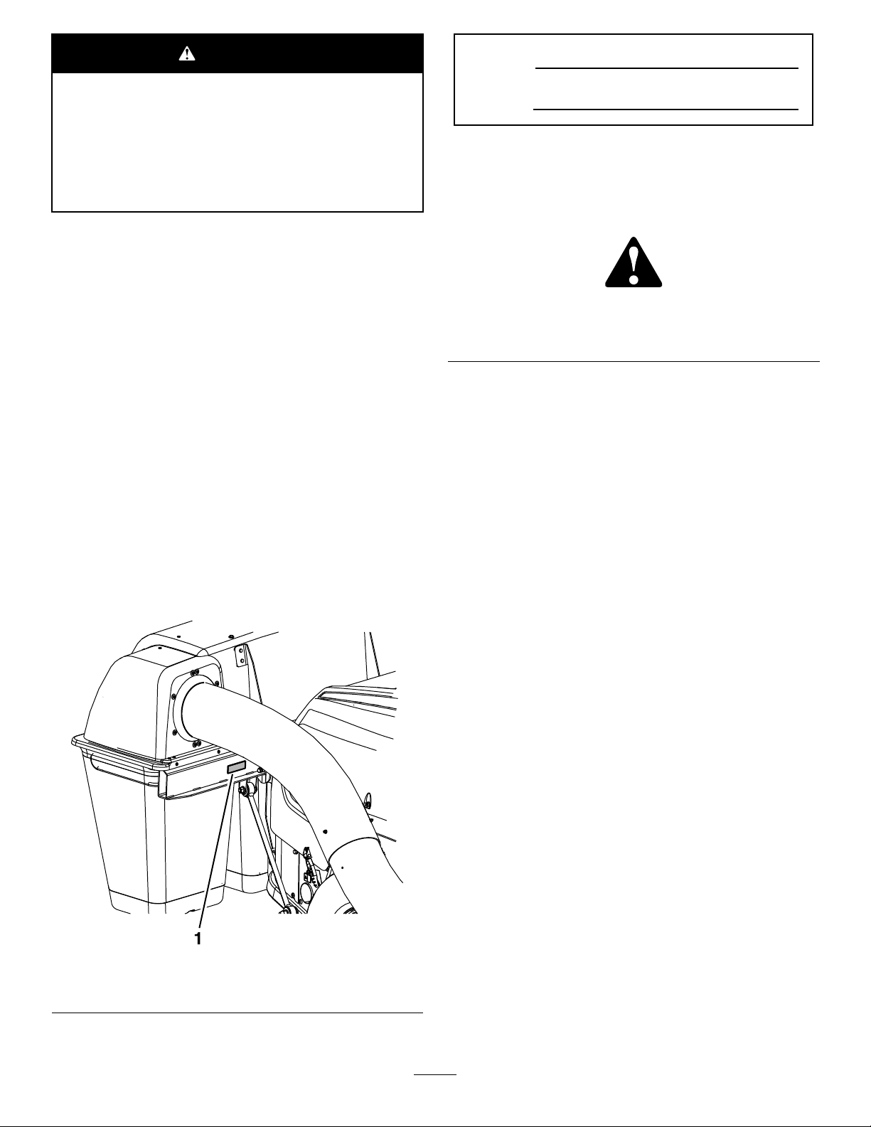
andserialnumbersofyourproductready.Figure1
identiesthelocationofthemodelandserialnumbers
ontheproduct.Writethenumbersinthespace
provided.
1.Modelandserialnumberlocation
©2018—TheToro®Company
8111LyndaleAvenueSouth
Bloomington,MN55420
Figure1
g241694
Contactusatwww.Toro.com.
2
PrintedintheUSA
AllRightsReserved
Page 3

Contents
Safety
Safety.......................................................................3
SafetyandInstructionalDecals..........................4
Setup........................................................................6
1PreparingtheMachine.....................................6
2InstallingtheWeights.......................................8
3InstallingtheBlowerAssembly.........................9
4InstallingtheMountBrackets..........................11
5InstallingtheHoodAssemblyand
Bags..............................................................12
6InstallingtheDischargeTubes.......................13
7AdjustingtheParkingBrake...........................15
8CheckingtheTirePressure............................15
Operation................................................................15
PositioningtheAdjustableBafe.......................15
EmptyingtheGrassBags.................................16
ClearingObstructionsfromtheBagger
System..........................................................16
RemovingtheCollectionSystemforSide
Discharge......................................................17
UsingtheGrassDeector.................................19
TransportingtheMachine.................................19
OperatingTips.................................................19
Maintenance...........................................................21
RecommendedMaintenanceSchedule(s)...........21
CleaningtheHoodScreen................................21
CleaningtheBaggerandBags.........................22
CheckingtheConditionoftheBelt....................22
InspectingtheBlowerBelt................................22
GreasingtheIdlerArm......................................22
InspectingtheBaggerAttachment....................23
InspectingtheMowerBlades............................23
InstallingtheMowerBlades..............................23
Storage...................................................................23
Troubleshooting......................................................24
DANGER
Theenginecanbecomehotwhenoperating.
Severeburnscanoccurfromcontactinghot
surfaces.
Allowengines,especiallythemufer,tocool
beforetouching.
DANGER
Debris,suchasleaves,grass,orbrushcan
catchre.Areintheengineareacancause
personalinjuryandpropertydamage.
•Keeptheengineandmuferareafreeof
debris.
•Takecarewhenopeningthebaggercover
tokeepdebrisfromfallingontotheengine
andmuferarea.
•Allowthemachinetocoolbeforestoringit.
•Becomefamiliarwiththesafeoperationofthe
equipment,withtheoperatorcontrols,andsafety
signs.
•Useextracarewithgrasscatchersorother
attachments.Thesecanchangetheoperating
characteristicsandthestabilityofthemachine.
•Followthemanufacturer'srecommendations
foraddingorremovingwheelweightsor
counterweightstoimprovestability.
•Donotuseagrasscatcheronsteepslopes.A
heavygrasscatchercouldcauselossofcontrol
oroverturnthemachine.
•Slowdownanduseextracareonhillsides.Be
suretotravelintherecommendeddirectionon
hillsides.Turfconditionscanaffectthestabilityof
themachine.Useextremecautionwhileoperating
neardrop-offs.
•Keepallmovementonslopesslowandgradual.
Donotmakesuddenchangesinspeed,directions
orturning.
•Thegrasscatchercanobstructtheviewtothe
rear.Useextracarewhenoperatinginreverse.
•Usecarewhenloadingorunloadingthemachine
intoatrailerortruck.
•Neveroperatewiththedischargedeectorraised,
removedoraltered,unlessusingagrasscatcher.
•Keephandsandfeetawayfrommovingparts.Do
notmakeadjustmentswiththeenginerunning.
•Stopthemachineonlevelground,disengage
thedrives,chockorblockthewheels,shutoff
theengine,andremovethekeybeforeleaving
3
Page 4
theoperator'spositionforanyreason,including
emptyingthegrasscatcheroruncloggingthe
chute.
•Ifyouremovethegrasscatcher,installany
dischargedeectororguardthatmighthavebeen
removedtoinstallthegrasscatcher.Donot
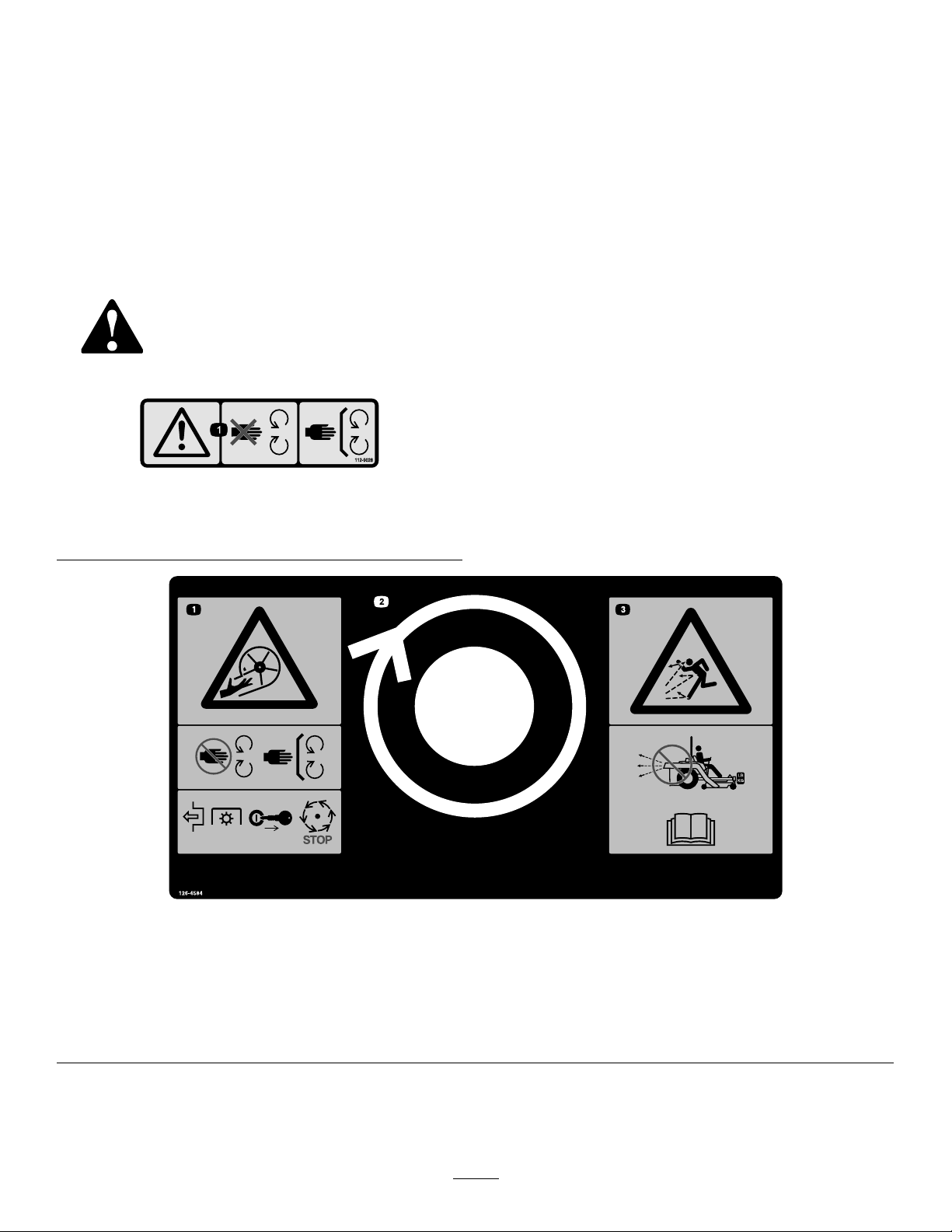
SafetyandInstructionalDecals
Safetydecalsandinstructionsareeasilyvisibletotheoperatorandarelocatednearanyarea
ofpotentialdanger.Replaceanydecalthatisdamagedormissing.
112-9028
operatethemachinewithouteithertheentiregrass
catcherorthegrassdeectorinplace.
•Grasscatchercomponentsaresubjecttowear,
damageanddeterioration,whichcouldexpose
movingpartsorallowobjectstobethrown.
Frequentlycheckcomponentsandreplace
withmanufacturer'srecommendedparts,when
necessary.
decal112-9028
1.Warning—stayawayfrommovingparts;keepallguardsin
place.
126-4584
1.Impeller/Rotatingbladeshazard—keephandsawayfrommovingparts.Keepallsafetydevicesinplaceandworking.Donot
reachintotheblowerunlesstherotationindicatorhasstopped.DisengagethePTO,shutofftheengine,removethekey ,
andwaitforallmovingpartstostop.
2.Rotationindicator
3.Thrownobjectshazard—high-speeddischargecancauseinjuryordeath.Donotruntheblowerwithouttheentirecollection
systeminstalledandlatched.ReadtheOperator’sManual.
decal126-4584
4
Page 5
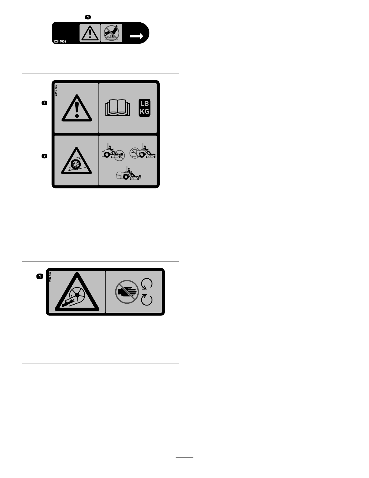
126-4659
1.Warning—hotpulley;allowtocool.
126-4662
1.Warning—readtheOperator’sManualforthecorrect
quantityofcounterbalanceweight(s).
2.Lossoftractionandsteeringorreducedstabilityhazard—Ez
Vaccounterbalanceweight(s)installedwithouttheEzV ac
maycauselossoftractionandsteeringcontrol.TheEzVac
installedwithouttheEzVaccounterbalanceweight(s)can
causereducedstability.Installweight(s)onlywhentheEz
Vacisinstalled.
decal126-4659
decal126-4662
126-4853
1.Impeller/Rotatingbladeshazard—keephandsawayfrom
movingparts.Keepallsafetydevicesinplaceandworking.
Donotreachintotheblowerunlesstherotationindicator
hasstopped.
decal126-4853
5
Page 6

Setup
LooseParts
Usethechartbelowtoverifythatallpartshavebeenshipped.
ProcedureDescription
1
2
3
4
5
6
Nopartsrequired
Weightassembly2
Bolt(3/8x6-1/2inches)
Bracketassembly2
Casterweight—20.4kg(45lb)
Casterweight—9.1kg(20lb)
Clevispin
Hairpincotter2
Locknut(3/8inch)
Washer2
Bolt(3/8x8inches)
Blowerbelt(fromBlowerandDriveKit)
Knob(fromBlowerandDriveKit)
Beltcover(fromBlowerandDriveKit)
Blowerassembly(fromtheBlowerand
DriveKit)
Spring(fromtheBlowerandDriveKit)
Lowermountbracket2
Bolt(3/8x2-1/2inches)
Thickwasher
Locknut(3/8inch)
Carriagebolt(3/8x3inches)
Hoodassembly1
Bag3
Rod-supportassembly2
Thrustwasher4
Baggerpin2
Flatwasher2
Mount-pinlanyard2
Locknut(1/2inch)
Lowertubeasembly1
Uppertube1
Hex-washerheadbolt(#10x3/4inch)
Flatwasher3
Locknut(#10)
Qty.
Use
–
2
2
6
2
4
2
1
1
1
1
1
6
5
8
2
2
3
3
Preparethemachine.
Installtheweights.
Installtheblowerassembly .
Installthemountbrackets.
Installthehoodassemblyandbags.
Installthedischargetubes.
7
8
Nopartsrequired
Nopartsrequired
–
–
Note:Determinetheleftandrightsidesofthemachinefromthenormaloperatingposition.
6
Adjusttheparkingbrake.
Checkthetirepressure.
Page 7
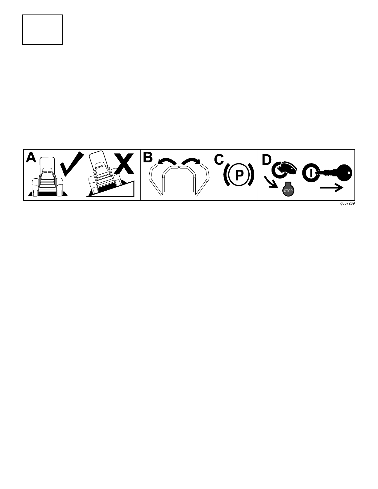
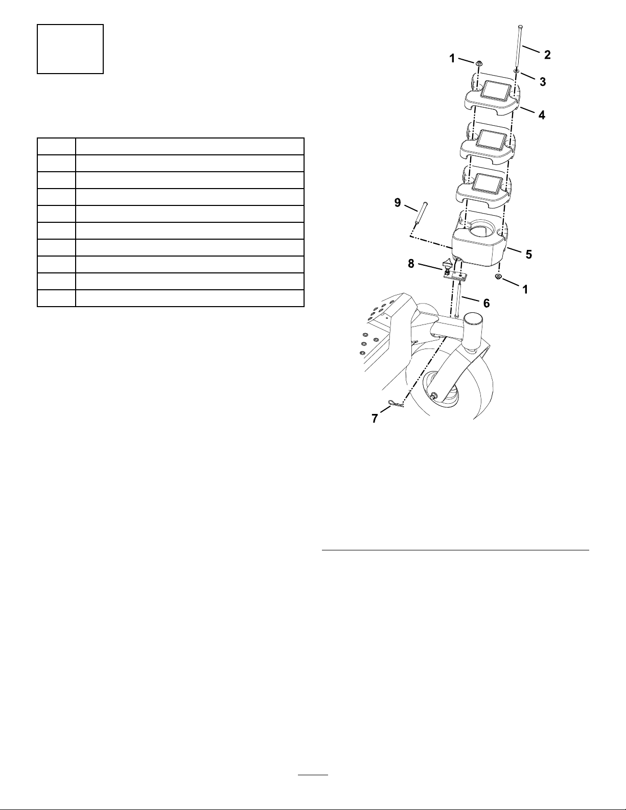
1
PreparingtheMachine
NoPartsRequired
Procedure
1.Parkthemachineonalevelsurface.
2.Movethemotion-controlleverstotheNEUTRAL-LOCKposition.
3.Engagetheparkingbrake.
4.Shutofftheengineandremovethekey.
g037289
Figure3
7
Page 8
2
InstallingtheWeights
Partsneededforthisprocedure:
2Weightassembly
2
Bolt(3/8x6-1/2inches)
2Bracketassembly
2
Casterweight—20.4kg(45lb)
6
Casterweight—9.1kg(20lb)
2
Clevispin
2Hairpincotter
4
Locknut(3/8inch)
2Washer
2
Bolt(3/8x8inches)
Procedure
1.Insertthebolt(3/8x6-1/2inches)intoholeon
thebottomsideofthebracketandtherearof
theremovable20.4kg(45lb)casterweight
(Figure4).
Carefullyplacetheweightandbracketassembly
ontothecasterarmcenteringtheholeofthe
weightoverthecasterwheel.
2.Securethebottomofthebrackettothecaster
armusingaclevispinandhairpincotter(Figure
4).
3.Tightentheknobontheweightassemblyuntilit
isclampedsecurelytothecasterarm(Figure4).
4.Install3casterweights(9.1kg(20lb)overthe
weightassemblyboltandstackthemsecurely
ontothe20.4kg(45lb)casterweight(Figure4).
5.Securetherearoftheweightassemblywitha
locknut(3/8inch)asshowninFigure4.
6.Installthebolt(3/8x8inches)andwasher
throughthetopofthefrontholesoftheweight
assemblyandsecureitusingalocknut(3/8
inch)asshowninFigure4.
7.Repeatthisprocedureontheothersideofthe
machine.
Figure4
1.Locknut(3/8inch)6.Bolt(3/8x6-1/2inches)
2.Bolt(3/8x8inches)
3.Washer8.Bracketassembly
4.Casterweight—9.1kg(20
lb)
5.Casterweight—20.4kg
(45lb)
7.Hairpincotter
9.Clevispin
g260769
8
Page 9
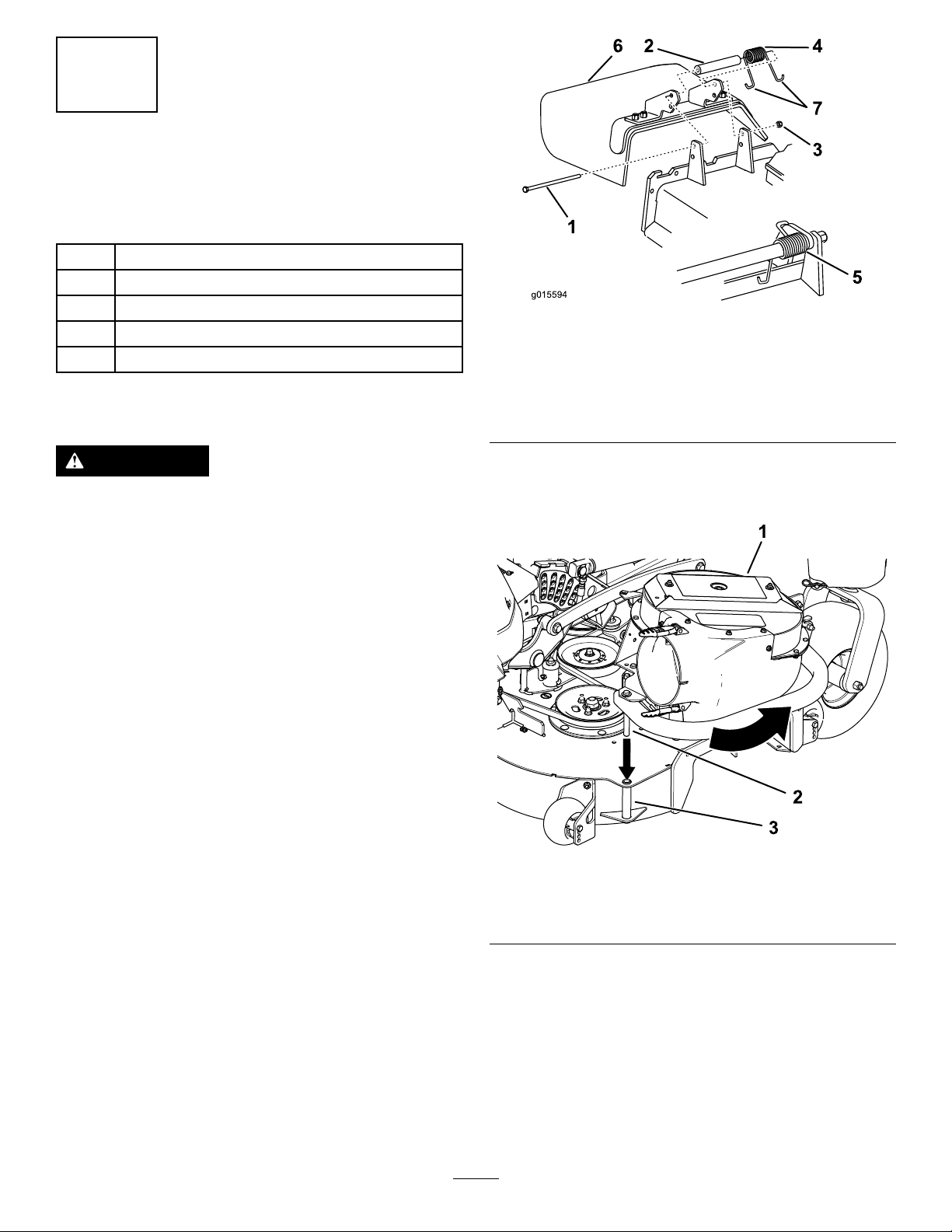
3
InstallingtheBlower Assembly
Partsneededforthisprocedure:
1
Blowerbelt(fromBlowerandDriveKit)
1
Knob(fromBlowerandDriveKit)
1
Beltcover(fromBlowerandDriveKit)
1
Blowerassembly(fromtheBlowerandDriveKit)
1
Spring(fromtheBlowerandDriveKit)
Procedure
Figure5
1.Bolt
2.Spacer6.Grassdeector
3.Locknut
4.Spring
5.Springinstalled
7.J-hookendofspring
g015594
WARNING
Anuncovereddischargeopeningcouldallow
thelawnmowertothrowobjectstowardyou
orbystanders,resultinginseriousinjury .
Also,contactwiththebladecouldoccur.
•Donotoperatethemachineunlessyou
installacoverplate,amulchplate,ora
grasschuteandcatcher.
•Ensurethatyouinstallthegrassdeector
whenthegrasschuteandcatcherare
removed.
1.Removethesidedischargechutefromthe
mowerdeck(Figure5).
Note:Saveallthehardwareandtheside
dischargechute.Installthesidedischargechute
whenthebaggerandblowerareremoved.
2.Inserttheblowerpivotpinintotheblower
supportandrotatetheblowerassemblyinward
towardthemachine(Figure6).
g260773
Figure6
1.Blowerassembly3.Blowersupport
2.Blowerpivotpin
9
Page 10

3.Pullthespring-loadedidlerbackandinstallthe
beltoverthedeckpulleyassembly(Figure7).
Figure7
1.Blowerpulley3.Deckpulley
2.Blowerbelt
4.Spring-loadedidler
4.Positionthebeltcoveratanangleandslideit
underthedeckframe(Figure8).
5.Pushdownontherearofthecoverandslideit
backwardundertheblower.
6.Withthebeltcoverrestingonthedeck,slideit
forwarduntilitseatsunderbothlipsonthedeck
(Figure9).
g260772
g260774
Figure9
1.Blower3.Knob
2.Beltcover4.Decklip
7.Securethebeltcoverusingtheknob(Figure9).
1.Blower
2.Beltcover
g242180
Figure8
3.Mowerframe
10
Page 11

4
InstallingtheMount Brackets
Partsneededforthisprocedure:
2Lowermountbracket
6
Bolt(3/8x2-1/2inches)
5
Thickwasher
8
Locknut(3/8inch)
2
Carriagebolt(3/8x3inches)
3.Looselyinstall1carriagebolt(3/8x3inches),1
thickwasher,and1locknut(3/8inch)intoeach
lowermountbracketthroughthefrontoftherear
bumper(Figure11).
Procedure
1.Looselyinstallalowermountbracketontheleft
andrightsideoftherearbumpercrosstube
(Figure10).
2.Alignthemountingholesandlooselyinstall
thebracketsusing2bolts(3/8x2-1/2inches),
2thickwashers,and2locknuts(3/8inch)as
showninFigure10.
Note:Youdonotinstallathickwasheronthe
left,outerside(Figure10).
Figure11
1.Carriagebolt(3/8x3
inches)
2.Thickwasher
4.Looselyinstall2bolts(3/8x2-1/2inches)and
2locknuts(3/8inch)atthefrontoftheframe
brackets(Figure11).
3.Locknut(3/8inch)
4.Bolt(3/8x2-1/2inches)
Note:Theheadoftheboltsshouldface
outwardoneachbracket(Figure1 1).
5.Tightenallthefasteners.
g260786
Figure10
1.Lowermountbracket4.Rearbumpercrosstube
2.Nowasherinstalledhere.
3.Thickwasher
5.Bolt(3/8x2-1/2inches)
6.Locknut(3/8inch)
g260785
11
Page 12

3.Liftthehopperassemblyandpivotitupward
towardtherearofthemachine.
5
InstallingtheHood AssemblyandBags
Partsneededforthisprocedure:
1Hoodassembly
3Bag
2Rod-supportassembly
4Thrustwasher
2Baggerpin
2Flatwasher
2Mount-pinlanyard
2
Locknut(1/2inch)
Procedure
Note:Use2peopleforthisprocedure.
1.Positionthehoodassemblyonitsback.
2.Pickupthebaggerframelegsandhookthe
notchontothelowerbagger-mountbar(Figure
12).
4.Securetherod-supportassemblytoeach
sideoftherearframeusing2baggerpins,2
atwashers,4thrustwashers,2mount-pin
lanyards,and2locknuts(1/2inch)asshownin
Figure13.
Figure13
1.Rod-supportassembly4.Mount-pinlanyard
2.Flatwasher
3.Baggerpin
5.Raisethehoodandinstallthebagassemblies
byslidingthebagframehooksontotheretaining
slotsonthehopperframe.
5.Locknut(1/2inch)
6.Thrustwasher
g260808
Figure12
1.Lowerbagger-mountbar2.Frameleg
6.Closeandlatchthehood.
g242492
12
Page 13

6
InstallingtheDischarge Tubes
Partsneededforthisprocedure:
1Lowertubeasembly
1Uppertube
3
Hex-washerheadbolt(#10x3/4inch)
3Flatwasher
3
Locknut(#10)
Procedure
1.DisengagethePTOandsettheparkingbrake.
2.Shutofftheengine,removethekey,andwait
forallmovingpartstostopbeforeleavingthe
operatingposition.
3.Lowerthemachinedecktothelowest
height-of-cutposition.
4.For60-inchdecks,shortentheuppertubeas
follows:
A.Locatethe3holesintheuppertube.
Measure16.5cm(6-1/2inches)upfromthe
endofthetubeandmarkthelocationinall
3areas(Figure14).
5.Installthelowertubeintotheuppertube(Figure
15).
g003424
Figure15
1.Lowertube2.Uppertube
6.Inserttheuppertubeintothehopperseal.
Pushin,thenpullout,sothatthesealis
extendedoutward.
7.Alignthedimpleontheuppertubewiththeend
ofthehoppersealandcenteritbetweenthe2
screws(Figure16).
Figure14
1.Newholelocation
2.Measure16.5cm(6-1/2inches).
3.Measureat3locations—76to89mm(3-1/2inches).
4.Cutthetubehere.
B.Drill3holes(4.8mmor3/16inch)asshown
inFigure14.
C.Measureat3locations—76to89mm(3
to3-1/2inches)fromtheendofthetube,
createthemarks,andapplymaskingtape
aroundthetubeasaguide(Figure14).
D.Carefullycutthetubeanddiscardtheend.
g009351
g007027
Figure16
1.Dimple
8.Slidethelowertubeontothebootandlatch
themtogether(Figure17).
Note:Thereisalatchonthetopandbottom
oftheblowerhousing.
13
Page 14

washers,and3locknuts(#10)asshownin
Figure19.
Installtheboltheadinsidethetubetoprovide
minimumobstructiontoow.Ensurethatthe
upperandthelowerendsareorientedproperly
asyouassemblethetubes(thepartinglines
shouldroughlylineup).
Figure17
1.Blowerassembly
2.Lowertube
3.Latch(triplebagger
shown)
9.Drillthe5.6mm(7/32inch)diameterholesin
thelowertubeusingtheuppertubeholesasthe
reference(Figure18).
g003423
g003392
Figure19
1.Lowertube
2.Uppertube5.Hex-washerheadbolt
3.Flatwasher
4.Locknut(#10)
(#10x3/4inch)
11.Withthebaggerendinrst,installthelower
tubeontotheblowerhousingandsecureitwith
thelatches.
Figure18
1.Drilltheholeshere.
10.Removethetubesfromthemachineand
assembletheupperandlowertubesusing3
hex-washerheadbolts(#10x3/4inch),3at
g007028
14
Page 15

Operation
7
AdjustingtheParking Brake
NoPartsRequired
Procedure
Ensurethattheparkingbrakeisadjustedproperly;
refertoyourOperator’sManual.
8
CheckingtheTirePressure
NoPartsRequired
Procedure
Note:Determinetheleftandrightsidesofthe
machinefromthenormaloperatingposition.
Important:Engagetheparkingbrakewhenyou
leavethemachineunattended.
WARNING
Toavoidpersonalinjury,followthese
procedures:
•Becomefamiliarwithalloperatingand
safetyinstructionsintheOperator's
Manualforthemowerbeforeusingthis
attachment.
•Neverremovethedischargetube,bags,
baggertop,orthechutewhiletheengine
isrunning.
•Alwaysshutofftheengine,waitforall
movingpartstostop,andremovethekey
beforeclearinganobstructionfromthe
baggingsystem.
•Neverdomaintenanceorrepairswhilethe
engineisrunning.
Note:Increasethetirepressureduetotheadditional
weight.
Checkandincreasetheairpressureinthefrontcaster
wheelsandreartires(Figure20).
Airpressureinthereartires:138kPa(20psi)
Airpressureinthefrontcasterwheels:172kPa
(25psi)
Figure20
PositioningtheAdjustable
Bafe
AdjustthebafetopositionB(middleposition)for
bagging;refertotheOperator’sManualforthe
machine.
g001055
g000947
Figure21
15
Page 16

EmptyingtheGrassBags
ClearingObstructionsfrom
Grassbagsareheavywhenfull.Becarefulwhen
liftingorhandlingagrassbagthatisfull.
1.Parkthemachineonalevelsurface.
2.Movethemotion-controlleverstothe
NEUTRAL-LOCKposition.
3.Engagetheparkingbrake.
4.Shutofftheengineandremovethekey.
5.Chockthetiresifonaslope.
6.Unlatchthebaggerlatch.
7.Openthebaggerhood.
8.Compressthedebrisintothebags.Withboth
hands,liftuponthebagandunhookitfromthe
baggerbracket.
9.Grabthehandleonthebottomofthebagand
tipitovertoemptythebag(Figure22).
theBaggerSystem
WARNING
Whenthebaggerisinoperation,theblower
canberotatingandcutofforinjurehands.
•Beforeadjusting,cleaning,repairingand
inspectingtheblower,oruncloggingthe
chute,shutofftheengine,waitforall
movingpartstostop,andremovethekey .
•Useastick,notyourhands,toremovean
obstructionfromtheblowerandtube.
•Keepyourface,hands,feet,andanyother
partofyourbodyorclothingawayfrom
concealed,moving,orrotatingparts.
1.Parkthemachineonalevelsurface.
2.Movethemotion-controlleverstothe
NEUTRAL-LOCKposition.
3.Engagetheparkingbrake.
Figure22
1.Bag2.Bottomhandle
10.Repeatfortheotherbags.
11.Installthebagtabintothenotchinthebagger
supportframe.
Note:Repeatthisstepfortheotherbags.
12.Lowerthebaggerhoodoverthebags.
4.Shutofftheengineandremovethekey.
5.Emptythebags.
6.Unlatchthelowertube.
7.Removethetubesfromthebagger.
8.Useastickorsimilarobject,notyourhands,to
removeandcleartheobstructionfromthetube
assembly.
Note:Inmostcases,thedebriscanbeshaken
outofthetubes.
9.Iftheblowerassemblyisplugged,unlatchthe
g003357
baggerblowerassembly ,removethebelt,and
swingitopen.
10.Useastickorsimilarobject,notyourhands,
toremoveandcleartheobstructionfromthe
blowerassembly.
11.Afteryouremovetheobstruction,installthe
completebaggersystemandresumeoperation.
13.Latchthebaggerhood.
16
Page 17

RemovingtheCollection SystemforSideDischarge
CAUTION
Failingtoremovethefrontbaggerweights
andoperatingthemachinewithoutthebagger
attachmentmaycauseanunstablecondition
whichcouldresultinalossofcontrol.
•Alwaysremovethefrontweightswhen
removingthebaggerattachment.
•Neveroperatethemachinewithoutthe
baggerattachmentandthefrontweights
stillinstalled.
1.Parkthemachineonalevelsurface.
2.Movethemotion-controlleverstothe
NEUTRAL-LOCKposition.
3.Engagetheparkingbrake.
4.Shutofftheengineandremovethekey.
5.Chockthetiresandemptythehopper.
6.Removethedischargetubebyreleasingthe
latchesattheblower.Slidethetubeoffthe
bloweroutletandremovetheupperendfrom
thehopper(Figure23).
g242158
Figure24
1.Belt-coverbracket4.Belt
2.Beltcover5.Decksheave
3.Knob
CAUTION
Thedecksheavebecomeshot.Touching
ahotdecksheavecancausesevere
burns.
Allowthedecksheavetocoolcompletely
beforeremovingthebelt.
Figure23
1.Hopper5.Beltcover
2.Clevispin
3.Casterarmweight
4.Hairpin8.Bag
6.Blower
7.Tubes
7.Removetheknobfromthebelt-coverbracket
andtakeoffthebeltcover(Figure24).
8.Pulltheidler-releasehandleandremovethebelt
fromtheuppergrooveofthedecksheave.
9.Unlatchthefrontendoftheblower,pivotthe
blowerback,andliftitoffthedeck(Figure25).
g242330
g242410
Figure25
1.Blowerlatch
2.Pivottheblowerawayfromthedeck.
17
Page 18

10.Installthedischargedeectorusingtheparts
showninFigure26.
Figure26
E.Removethebracketassemblyandall
mountinghardwarefromthecasterarm.
F.Repeatthisprocedureontheothersideof
themachine.
g015594
1.Bolt
2.Spacer6.Grassdeector
3.Locknut
4.Spring
5.Springinstalled
7.J-hookendofspring
WARNING
Anuncovereddischargeopeningcould
allowthelawnmowertothrowobjectsat
youorbystanders,resultinginserious
injury.Also,contactwiththebladecould
occur.
•Neveroperatethelawnmowerunless
youinstallacoverplate,amulch
plate,oragrasschuteandcatcher.
•Ensurethatthegrassdeectorisin
thedownposition.
11.Installtheplasticbeltcoverandtightenthe
knobs.
12.Removethebagsfromthehopperassemblyby
openingthehopperandliftinguptherearofthe
bagandunhookingthefrontclip.
13.Removethehopperassembly.
Figure27
1.Bolt(3/8x6-1/2inches)
2.Knob
3.Bracket
4.Casterweight—20.4kg
(45lb)
5.Clevispin10.Bolt(3/8x8inches)
6.Hairpincotter
7.Casterweight—9.1kg(20
lb)
8.Locknut(3/8inch)
9.Washer
g242048
14.Removethecasterweightsasfollows:
A.Removethelocknut(3/8inch)fromthe
bottomofthe20.4kg(45lb)weight
mountedtothecasterarm(Figure27).
B.Removethebolt(3/8x8inches)and
washer(Figure27).
C.Removethelocknut(3/8inch)fromthetop
9.1kg(20lb)casterweight(Figure27).
D.Carefullyliftandremoveeachweightfrom
thecasterarms.
15.Removethecasterweightsbylooseningthe
clampingknobsuntilyoucanmovetheweight
relativetothecasterarm.Removethehairpin
cottersandclevispinsthatsecuretheweights
tothecasterarms.Carefullylifttheweightsoff
ofthecasterarms.
18
Page 19

UsingtheGrassDeector
DANGER
Withoutthegrassdeector,dischargecover,
orcompletegrasscatcherassemblymounted
inplace,youandothersareexposedtoblade
contactandthrowndebris.Contactwith
rotatingmowerblade(s)andthrowndebris
willcauseinjuryordeath.
•Alwaysinstallthegrassdeectorwhen
removingthebaggerandchangingtoside
dischargemode.
•Ifthegrassdeectoriseverdamaged,
replaceitimmediately.Thegrassdeector
routesmaterialdowntowardtheturf.
•Neverputyourhandsorfeetunderthe
mowerdeck.
CuttingHeight
Donotsetthemowercuttingheighttoolowbecause
longgrasssurroundingthemowercanpreventair
fromgettingunderthemowerandenteringthe
baggingsystem.Ifenoughairdoesnotgetunderthe
mower,thebaggingsystemwillplug.
CuttingFrequency
Cutthegrassoften,especiallywhenitgrowsrapidly.
Youwillhavetocutyourgrasstwiceifitgets
excessivelylong.
CuttingTechnique
Forbestlawnappearance,besuretoslightlyoverlap
themowerintothepreviouslycutarea.Thishelps
reducetheloadontheengineandreducesthechance
ofpluggingthechuteanddischargetube.
•Nevertrytoclearthedischargeareaor
mowerbladesunlessyoumovethepower
take-off(PTO)totheOFFposition,rotate
theignitionkeytooffandremovethekey.
•Neveruseyourhandstoclearthe
dischargearea.Useastickorsimilar
objecttoclearthedischargearea.
TransportingtheMachine
Donotleavegrassordebrisinthebaggerwhile
transportingthemachine.
DANGER
Transportingthemachinewithgrassordebris
inthebaggercandamagethemachine.
Donotleavegrassordebrisinthebagger
whiletransportingthemachine.
OperatingTips
TipsforBagging
RememberingtheSize
Rememberthatthemachineislongerandwiderwith
thisattachmentinstalled.Byturningtoosharplyin
connedplacesyoumaydamagetheattachment.
BaggingSpeed
Mostoftenyouwillbagwiththemowerthrottleinthe
Fastpositionanddriveatanormalgroundspeed.
However,inextremelydryanddustygrass,youmay
wanttoslightlyreducethethrottlespeedandincrease
thegroundspeedofthemower.Thebaggingsystem
mayplugifyoudrivetoofastandtheenginespeed
getstooslow.Onhillsitmaybenecessarytoslow
themowergroundspeed.Thishelpsmaintainthe
enginespeedandbaggingefciency.Mowdownhill
wheneverpossible.
CAUTION
Asthebaggerlls,extraweightisaddedto
thebackofthemachine.Ifyoustopand
startsuddenlyonhills,youmaylosesteering
controlorthemachinemaytip.
•Donotstartorstopsuddenlywhengoing
uphillordownhill.Avoiduphillstarts.
•Ifyoudostopthemachinewhengoing
uphill,disengagethebladecontrol.Then
backdownthehillusingaslowspeed.
•Avoidsuddenturnsorrapidspeed
changesonslopes.
•Donotoperatethemachinewithoutthe
baggerattachmentandthefrontweights
stillinstalled.
Trimming
Alwaystrimwiththeleftsideofthemower.Donottrim
withtherightsideofthemowerbecauseyoucould
damagethebaggerchuteanddischargetube.
BaggingLongGrass
Excessivelylonggrassisheavyandmaynotbe
propelledcompletelyintothegrassbags.Ifthis
happens,thedischargetubeandchutemayplug.T o
avoidpluggingthebaggingsystem,mowthegrass
19
Page 20

atahighheightofcut,thenlowerthemowertoyour
normalcuttingheightandrepeatthebaggingprocess.
BaggingWetGrass
Alwaystrytocutgrasswhenitisdrybecauseyour
lawnwillhaveaneatappearance.Ifyoumustcutwet
grass,usetheconventionalsidedischargefeatureof
themower.Severalhourslater,whentheclippings
aredry,installthecompletebaggerattachmentand
vacuumupthegrassclippings.
SignsofPlugging
Asyouarebagging,asmallamountofgrassclippings
normallyblowoutthefrontofthemower.Anexcessive
amountofclippingsblowingoutindicatesthatthe
bagsarefullorthesystemisplugged.
20
Page 21

Maintenance
RecommendedMaintenanceSchedule(s)
MaintenanceService
Interval
Aftertherst8hours
Aftertherst10hours
Beforeeachuseordaily
Every25hours
Every50hours
Beforestorage
MaintenanceProcedure
•Inspecttheblowerbelt.
•Inspectthebagger.
•Cleanthehoodscreen.
•Cleanthebagger.
•Inspecttheblowerbelt.
•Greasetheidlerarm.
•Checktheconditionofthebelt.
•Inspectthebagger.
CAUTION
Ifyouleavethekeyintheignitionswitch,someonecouldaccidentlystarttheengineand
seriouslyinjureyouorotherbystanders.
Removethekeyfromtheignitionanddisconnectthewirefromthesparkplugbeforeyoudo
anymaintenance.Setthewireasidesothatitdoesnotaccidentallycontactthesparkplug.
DANGER
Enginescanbecomehotwhentheyareoperating.Severeburnscanoccurfromcontactinghot
surfaces.
Allowengines,especiallythemufer,tocoolbeforetouching.
DANGER
Debris,suchasleaves,grass,orbrushcancatchre.Areintheengineareacancause
personalinjuryandpropertydamage.
•Keeptheengineandmuferareafreeofdebrisaccumulation.
•Takecarewhenopeningthebaggercovertokeepdebrisfromfallingontotheengineand
muferarea.
•Allowthemachinetocoolbeforestoringit.
CleaningtheHoodScreen
ServiceInterval:Beforeeachuseordaily
Thescreensneedtobecleanedbeforeeachuse.In
wetgrasstheywillneedtobecleanedmoreoften.
1.Parkthemachineonalevelsurface.
2.Movethemotion-controlleverstothe
NEUTRAL-LOCKposition.
3.Engagetheparkingbrake.
4.Shutofftheengineandremovethekey.
5.Openthebaggerhood.
6.Cleanthedebrisfromthescreen.
7.Closethebaggerhood.
21
Page 22

CleaningtheBaggerand
GreasingtheIdlerArm
Bags
ServiceInterval:Beforeeachuseordaily
Cleanthebaggerdaily.
1.Washtheinsideandoutsideofthebagger
hood,bags,tube,andtheundersideofthe
mowerdeck.Useamildautomotivedetergent
toremovedirt.
2.Removemattedgrassfromallparts.
3.Afterwashingalltheparts,letthemdry
thoroughly.
Note:Withallpartsinstalled,startandrunthe
machineforaminutetodrythem.
CheckingtheConditionof theBelt
ServiceInterval:Every50hours
1.Parkthemachineonalevelsurface.
ServiceInterval:Every25hours
Greasethebaggerbeltidlerarm(Figure28)every
25hours.
g003455
Figure28
2.Movethemotion-controlleverstothe
NEUTRAL-LOCKposition.
3.Engagetheparkingbrake.
4.Shutofftheengineandremovethekey.
5.Inspectthebeltfordamageorwear.Replace
thebeltwithoneofthefollowing:
DeckPartNo.
60-inchdeck103-0866
72-inchdeck103-0867
InspectingtheBlowerBelt
ServiceInterval:Aftertherst8hours
Every25hours
Checkbeltsforcracks,frayededges,burnmarksor
anyotherdamage.Replacedamagedbelts.
22
Page 23

InspectingtheBagger
Storage
Attachment
ServiceInterval:Aftertherst10hours
Beforestorage
1.Checkthechute,dischargetube,andthebagger
top.Replacethesepartsiftheyarecrackedor
broken.
2.Tightenallnuts,bolts,andscrews.
3.Inspectallthefastenersandlatches;replace
anythataremissingordamaged.
4.Inspectthegrassbagsfordeterioration.
WARNING
Youorbystanderscouldbeseverely
injuredbyyingdebrisorthrownobjects
thatmaypassthroughtorn,worn,or
deterioratedgrassbags.
•Checkthegrassbagsforholes,rips,
wear,andotherdeterioration.
•Ifthebaghasdeteriorated,install
newgrassbagssuppliedby
themanufacturerofthisbagger
attachment.
1.Cleanthebaggerattachment;refertoCleaning
theBaggerandBags(page22).
2.Inspectthebaggerattachmentfordamage;refer
toInspectingtheBaggerAttachment(page23).
3.Ensurethatthebagsareemptyandthoroughly
dry.
4.Checkthebeltforwearorcracks.
5.Storethemachineinaclean,dryplace,outof
directsunlight.Ifyoumuststorethemachine
outside,coveritwithaweatherproofcover.This
protectstheplasticpartsandextendsthelifeof
themachine.
InspectingtheMower Blades
1.Inspectthemowerbladesregularlyand
wheneverabladestrikesaforeignobject.
2.Ifbladesarebadlywornordamaged,install
newblades.RefertoyourmachineOperator's
Manualforcompleteblademaintenance.
InstallingtheMowerBlades
Inmostmowingconditions,thestandardhigh-lift
bladesprovidethebestbaggingperformance.
TheT oroAtomicbladeisrecommendedforbagging
leavesindryconditions.Indrydustyconditions,the
mediumliftorlowliftbladeswillreducedustanddirt
blowoutwhileprovidingeffectivebaggingairow.
ContactanAuthorizedServiceDealerfortheproper
bladesfordifferentmowingconditions.
RefertothemachinesOperator'sManualformore
informationoninstallingblades.
23
Page 24

Troubleshooting
Problem
Thereisabnormalvibration.
Thereisreducedbaggingperformance.
Theblowerandtubesplugtoofrequently.
PossibleCauseCorrectiveAction
1.Thecuttingblade(s)is/arebentor
unbalanced.
2.Theblade-mountingboltisloose.2.Tightentheblade-mountingbolt.
3.Theblowerpulleyorpulleyassembly
isloose.
4.Thebaggerbeltisworn.4.Replacethebelt.
5.Theblowerfanblade(s)is/arebentor
unbalanced.
1.Theenginespeedislow.
2.Thebagger-hoodscreenisplugged.2.Removethedebris,leavesorgrass
3.Loosebaggerbelt.3.Replacethebaggerbelt.
4.Theblowerortubeisplugged.4.Locateandremovethepluggeddebris.
5.Thebagsarefull.
1.Thebagsaretoofull.1.Dumpthebagsmorefrequently.
2.Theenginespeedislow.
3.Thegrassistoowet.
4.Thegrassistoolong.
5.Thescreeninthehoodisplugged.5.Removethedebris,leavesorgrass
6.Thegroundspeedistoofast.6.Drivesloweratfullthrottle.
7.Thebaggerbeltisworn.7.Replacethebelt.
1.Installnewcuttingblade(s).
3.Tightentheappropriatepulley.
5.ContactanAuthorizedServiceDealer.
1.Alwaysoperatethebaggeratfull
throttle.
clippingsfromthescreen.
5.Emptythebags.
2.Alwaysoperatethebaggeratfull
throttle.
3.Cutthegrasswhenitisdry.
4.Cutnomorethan51to76mm(2to
3inches)or1/3ofthegrassheight,
whicheverisless.
clippingsfromthescreen.
Thereisdebrisblowout.
Theblowerimpellerdoesnotspinfreely.
1.Thebagsaretoofull.1.Dumpthebagsmorefrequently.
2.Thegroundspeedistoofast.2.Drivesloweratfullthrottle.
3.Themowerdeckisnotleveled.
1.Theblowerisplugged.1.Removethedebris,leavesorgrass
2.Theimpellerisnotaligned.
3.Seethemoweroperator'smanualfor
levelingthemowerdeck.
clippingsfromtheblowerimpeller .
2.ContactanAuthorizedServiceDealer.
24
Page 25

Notes:
Page 26

Notes:
Page 27

DeclarationofIncorporation
TheT oroCompany,8111LyndaleAve.South,Bloomington,MN,USAdeclaresthatthefollowingunit(s)
conform(s)tothedirectiveslisted,wheninstalledinaccordancewiththeaccompanyinginstructionsontocertain
ToromodelsasindicatedontherelevantDeclarationsofConformity.
ModelNo.
SerialNo.
78560
400000000andup
andUp
ProductDescriptionInvoiceDescription
TripleBaggingSystem,Z
MasterProfessional7500-D
SeriesRidingMowerwith
60inor72inTURBOFORCE
SideDischargeMower
TRIPLEBAGASSEMBLY
GeneralDescription
Bagger
Directive
2006/42/EC,
2000/14/EC
RelevanttechnicaldocumentationhasbeencompiledasrequiredperPartBofAnnexVIIof2006/42/EC.
Wewillundertaketotransmit,inresponsetorequestsbynationalauthorities,relevantinformationonthispartly
completedmachinery.Themethodoftransmissionshallbeelectronictransmittal.
ThismachineryshallnotbeputintoserviceuntilincorporatedintoapprovedT oromodelsasindicatedonthe
associatedDeclarationofConformityandinaccordancewithallinstructions,wherebyitcanbedeclaredin
conformitywithallrelevantDirectives.
Certied:
AuthorizedRepresentative:
MarcelDutrieux
ManagerEuropeanProductIntegrity
ToroEuropeNV
Nijverheidsstraat5
2260Oevel
Belgium
JohnHurst
Sr.EngineeringManager
811 1LyndaleAve.South
Bloomington,MN55420,USA
July10,2018
Tel.+3216386659
Page 28

 Loading...