


FormNo.3440-329RevA
60inand72inDFSE-ZVac
CollectionSystem
Z500SeriesZMaster
ModelNo.78544—SerialNo.280000001andUp
ModelNo.78545—SerialNo.280000001andUp
®
Mowers
™
Registeratwww.T oro.com.
OriginalInstructions(EN)
CV
*3440-329*A

Introduction
Readthisinformationcarefullytolearnhowtooperate
andmaintainyourproductproperlyandtoavoid
injuryandproductdamage.Youareresponsiblefor
operatingtheproductproperlyandsafely .
YoumaycontactT orodirectlyatwww.T oro.com
forproductsafetyandoperationtrainingmaterials,
accessoryinformation,helpndingadealer,orto
registeryourproduct.
g007732
Figure2
BaggerSerialNumber
1.Baggermodelandserialnumberlocation
Wheneveryouneedservice,genuineToroparts,or
additionalinformation,contactanAuthorizedService
DealerorToroCustomerServiceandhavethemodel
andserialnumbersofyourproductready.Figure1
andFigure2identiesthelocationofthemodeland
serialnumbersontheproduct.Writethenumbersin
thespaceprovided.
Figure1
1.Blowermodelandserialnumberlocation
ModelNo.
SerialNo.
Thismanualidentiespotentialhazardsandhas
safetymessagesidentiedbythesafetyalertsymbol
(Figure3),whichsignalsahazardthatmaycause
seriousinjuryordeathifyoudonotfollowthe
recommendedprecautions.
g000502
Figure3
1.Safetyalertsymbol
Thismanualuses2wordstohighlightinformation.
Importantcallsattentiontospecialmechanical
g003368
informationandNoteemphasizesgeneralinformation
worthyofspecialattention.
ModelNo.
SerialNo.
©2020—TheToro®Company
8111LyndaleAvenueSouth
Bloomington,MN55420
Contents
Safety.......................................................................3
SafetyandInstructionalDecals..........................4
Setup........................................................................5
1PreparingtheMower........................................6
2InstallingtheBaggerMountingBracket............6
3InstallingtheHandleAssembly........................8
4TighteningallMountingBolts...........................9
5InstallingtheBaggerAssembly........................9
6RoutingtheBlowerBeltintotheBlower
Assembly......................................................10
7InstallingtheBlowerAssembly.......................10
8SizingtheUpperTubefor152cm(60inch)
MowerswithGasEngines.............................12
9InstallingtheDischargeTubes.......................13
10InstallingtheBeltCover...............................16
Contactusatwww.Toro.com.
2
PrintedintheUSA
AllRightsReserved

11InstallingtheWeights...................................17
12AdjustingtheParkingBrake.........................17
13CheckingtheTirePressure..........................18
Operation................................................................19
PositioningtheAdjustableBafe.......................19
EmptyingtheBagger........................................20
ClearingObstructionsfromtheCollection
System..........................................................20
RemovingtheBagger.......................................20
UsingtheGrassDeector.................................21
TransportingMachines.....................................21
OperatingTips.................................................21
Maintenance...........................................................23
RecommendedMaintenanceSchedule(s)...........23
CleaningtheBaggerScreen.............................23
CleaningtheCollectionSystem........................23
InspectingtheBlowerBelt................................23
ReplacingtheBlowerBelt.................................23
CheckingandAdjustingtheBlower
Latch.............................................................24
GreasingtheIdlerArmandHandle
Pivot..............................................................24
InspectingtheCollectionSystem......................25
AdjustingtheDoorClosing...............................25
AdjustingtheDoorOpening..............................25
AdjustingtheLatches.......................................26
InspectingtheMowerBlades............................26
InstallingtheMowerBlades..............................26
InstallingtheGrassDeector............................27
Storage...................................................................28
Troubleshooting......................................................29
Safety
Thefollowinglistcontainssafetyinformationspecic
toToroproductsandothersafetyinformationyou
mustknow.
•Becomefamiliarwiththesafeoperationofthe
equipment,withtheoperatorcontrols,andsafety
signs.
•Useextracarewithgrasscatchersorother
attachments.Thesecanchangetheoperating
characteristicsandthestabilityofthemachine.
•Followthemanufacturer'srecommendations
foraddingorremovingwheelweightsor
counterweightstoimprovestability.
•Donotuseagrasscatcheronsteepslopes.A
heavygrasscatchercouldcauselossofcontrol
oroverturnthemachine.
•Slowdownanduseextracareonhillsides.Be
suretotravelintherecommendeddirectionon
hillsides.Turfconditionscanaffectthemachine's
stability.Useextremecautionwhileoperatingnear
drop-offs.RefertothetractionunitOperator's
Manualforoperationnearslopesanddrop-offs.
•Keepallmovementonslopesslowandgradual.
Donotmakesuddenchangesinspeed,directions
orturning.
•Thegrasscatchercanobstructtheviewtothe
rear.Useextracarewhenoperatinginreverse.
•Usecarewhenloadingorunloadingthemachine
intoatrailerortruck.Ifthemachineistobedriven
ontoatruckortrailerwiththehopperfull,always
backuptheramp.
•Neveroperatewiththedischargedeectorraised,
removedoraltered,unlessusingagrasscatcher.
•Keephandsandfeetawayfrommovingparts.Do
notmakeadjustmentswiththeenginerunning.
•Stoponlevelground,disengagedrives,chock
orblockwheels,shutoffenginebeforeleaving
theoperator'spositionforanyreasonincluding
emptyingthegrasscatcheroruncloggingthe
chute.
•Ifyouremovethegrasscatcher,besuretoinstall
anydischargedeectororguardthatmighthave
beenremovedtoinstallthegrasscatcher.Donot
operatethemowerwithouteithertheentiregrass
catcherorthegrassdeectorinplace.
•Stoptheenginebeforeremovingthegrasscatcher
oruncloggingthechute.
•Donotleavegrassingrasscatcherforextended
periodsoftime.
•Grasscatchercomponentsaresubjecttowear,
damageanddeterioration,whichcouldexpose
movingpartsorallowobjectstobethrown.
Frequentlycheckcomponentsandreplace
3

withmanufacturer'srecommendedparts,when
necessary.
SafetyandInstructionalDecals
Safetydecalsandinstructionsareeasilyvisibletotheoperatorandarelocatednearanyarea
ofpotentialdanger.Replaceanydecalthatisdamagedorlost.
1-653554
decal1-653554
decal106-3339
106-3339
decal1-653558
1-653558
decal98-5954
98-5954
decal103-3507
103-3507
4

Setup
LooseParts
Usethechartbelowtoverifythatallpartshavebeenshipped.
ProcedureDescription
1
2
3
4
5
6
7
8
9
10
11
Nopartsrequired
Baggermountingbracket1
Baggersideplate2
Spacer
Bolt(3/8x1-1/2inches)
Bolt(3/8x1inch)(forZ593mowers
only)
Flangenut(3/8inch)
Curvedwasher
Handleassembly1
Washer2
Bolt(3/8x1-1/4inches)
Clevis-pinspring
Locknut(3/8inch)
Nopartsrequired
Baggerassembly1
Clevispin
Hairpincotter2
Blowerbelt(fromtheBlowerandDrive
Kit)
Blowerassembly(fromtheBlowerand
DriveKit)
Spring(fromtheBlowerandDriveKit)
Uppertube1
Uppertube1
Lowertube1
Bolt(#10x3/4inches)
Locknut(#10)
Washer(7/32inch)
Beltcover(fromtheBlowerandDrive
Kit)
Casterweight(ifneeded)
U-bolt2
Nut(1/2inch)
Lockwasher(1/2inch)
Plate2
Topweight(for60inchmowerdecks
only)
Qty.
–
2
14
2
14
14
3
1
3
–
2
1
1
1
3
3
3
1Installthebeltcover.
2
4
4
2
Preparethemower.
Installthebaggermountingbracket.
Installthehandleassembly .
Tightenallmountingbolts.
Installthebaggerassembly .
Routetheblowerbeltintotheblower
assembly.
Installtheblowerassembly .
Sizetheuppertubefor152cm(60inch)
mowerswithgasengines.
Installthedischargetubes.
Installtheweights.
Use
12
13
Nopartsrequired
Nopartsrequired
5
–
–
Adjusttheparkingbrake.
Checkthetirepressure.

Note:Determinetheleftandrightsidesofthemachinefromthenormaloperatingposition.
1
PreparingtheMower
NoPartsRequired
Procedure
Performthefollowingproceduretopreparethemower
forattachingtheblowerandnishingkit.
1.DisengagethePTO,movethemotion-control
leverstotheNEUTRAL-LOCKEDpositionandset
theparkingbrake.
2.Stoptheengine,removethekey ,andwait
forallmovingpartstostopbeforeleavingthe
operatingposition.
3.Repairallbentordamagedareasofmower
deckandreplaceanymissingparts.
4.Cleanthemowerofanydebrisonthedeckor
rearpartofthemowertoeaseinstallation.
2
InstallingtheBagger
MountingBracket
Partsneededforthisprocedure:
1Baggermountingbracket
2Baggersideplate
2
Spacer
14
Bolt(3/8x1-1/2inches)
2
Bolt(3/8x1inch)(forZ593mowersonly)
14
Flangenut(3/8inch)
14
Curvedwasher
Procedure
Important:Donottightenanyboltsuntilboth
sidebracketsandbaggermountingbracketaret
looseonthemachine.
RefertoTighteningtheMountingBoltsforthe
correctproceduretotightenthebolts.
1.Removethebolts,nuts,andwashersholding
therollbartoonesideofthemachine.Discard
thenuts,bolts,andwashers(Figure4,Figure
5,andFigure6).
2.Installthebaggersideplateandtherollbar
sectiontothesideofthemachineusing4bolts
(3/8x1-1/2inches),4curvedwashers(3/8
inch),and4angenuts(3/8inch)(Figure4,
Figure5,andFigure6).
3.Repeatthestepsabovefortheoppositeside
(Figure4,Figure5,andFigure6).
Note:Makesurethecurvedwashersare
installedasshowninFigure4,Figure5,and
Figure6.
4.Installthebaggermountingbrackettotheleft
andrightsidebaggerbracketswith4bolts(3/8
x1-1/2inches),4curvedwashers(3/8inch),
and4angenuts(3/8inch)(Figure4,Figure
5,andFigure6).
5.Installthebaggermountingbrackettothe
rearframeofthemachinewith2bolts(3/8x
1-1/2inches)(use2bolts(3/8x1inch)for
Z593mowersasshowninFigure5),2curved
washers(3/8inch),and2angenuts(3/8inch)
(Figure4,Figure5,andFigure6).
6

Figure4
ForZ500GasMowers
1.Bolt(3/8x1-1/2inches)6.ROPS
2.Curvedwasher(3/8inch)7.Flangenut(3/8inch)
3.Baggermountingbracket
4.Spacer
5.Baggersideplate
8.Sideviewofbaggerside
plate
9.Holestousewhen
installingthesidebracket
g003379
g003380
ForKubotaDieselMowers
1.Bolt(3/8x1inch)
2.Curvedwasher(3/8inch)
3.Baggermountingbracket
Figure5
6.Baggersideplate
7.ROPS
8.Flangenut(3/8inch)
4.Bolt(3/8x1-1/2inches)9.Sideviewofbaggerside
plate
5.Spacer
10.Holestousewhen
installingthesidebracket
7

Figure6
ForDaihatsuDieselMowers
3
InstallingtheHandle
Assembly
Partsneededforthisprocedure:
1Handleassembly
2Washer
3
Bolt(3/8x1-1/4inches)
1
Clevis-pinspring
3
Locknut(3/8inch)
Procedure
1.Positionthehandleassemblybetweenthe
ROPSrollbarandthebaggermountingbracket
(Figure8).
2.Installthehandleassemblytothebagger
mountingbracketandthemachinewith3bolts
g003378
(3/8x1-1/4inches)and3locknuts(3/8inch)
(Figure7andFigure8).
1.Bolt(3/8x1-1/2inches)6.ROPS
2.Curvedwasher ,(3/8inch)7.Flangenut(3/8inch)
3.Baggermountingbracket
4.Spacer
5.Baggersideplate
8.Sideviewofbaggerside
plate
9.Holestousewhen
installingthesidebracket
1.Handleassembly
2.Washer
g008105
Figure7
3.Bolt(3/8x1-1/4inches)
4.Nut(3/8inch)
8

Figure9
g007701
Figure8
1.Handleassembly
2.Bolt(3/8x1-1/4inches)
3.Washer
3.Installthebaggerarmlinkagetothebagger
assemblywithaclevispinspring(Figure9).
4.Nut(3/8inch)
5.Thisboltisnotusedon
Kubotapoweredmachines
1.Baggerarmlink
2.Baggerassembly
3.Clevispinspring
4
TighteningallMounting
Bolts
g007703
NoPartsRequired
Procedure
Thefollowingstepsarethecorrectsequenceto
tightenthesidebracketsandthebaggermounting
bracket.Allmountingboltsneedtobetorquedto48
N⋅m(35ft-lb).
1.Tightenthebaggermountingbrackettotherear
framerst.
2.TightentheROPSandsidebracketstotheside
ofthemower.
3.Ifthebaggermountingbracketmovessideto
sidean1/8inchormore,installoneorboth
ofthespacersbetweenthebaggermounting
bracketandmountingplates(Figure4,Figure
5,andFigure6).
4.Tightenthebaggermountingbrackettotheside
brackets.
9

5
6
InstallingtheBagger
Assembly
Partsneededforthisprocedure:
1Baggerassembly
2
Clevispin
2Hairpincotter
Procedure
1.Installthebaggerassemblyontothebagger
mountingbracket(Figure10).
2.Installthe2clevispinsintothebaggerassembly
andbaggermountingbracket.Secureitwith2
hairpincotters(Figure10).
RoutingtheBlowerBelt
intotheBlowerAssembly
Partsneededforthisprocedure:
1
Blowerbelt(fromtheBlowerandDriveKit)
Procedure
1.Installthebeltaroundtheblowerpulley(Figure
11).
2.Installthespringtotheidlerarmandthepegon
theblowerassembly(Figure11).
Figure10
1.Hoodassembly3.Hairpincotter
2.Clevispin
4.Baggermountingbracket
g003398
Figure11
1.Idlerpulley4.Peg
2.Mower-deckpulley5.Belt
g007702
3.Spring
6.Blowerpulley
10

7
InstallingtheBlower
Assembly
Partsneededforthisprocedure:
1
Blowerassembly(fromtheBlowerandDriveKit)
1
Spring(fromtheBlowerandDriveKit)
Procedure
WARNING
Anuncovereddischargeopeningcouldallow
thelawnmowertothrowobjectsatyouor
bystanders,resultinginseriousinjury.Also,
contactwiththebladecouldoccur.
2.Slidetheblower-assemblypegintothepivot
hole.For152cm(60inch)mowersreferto
Figure13andfor183cm(72inch)mowersrefer
toFigure14.
•Neveroperatethelawnmowerunlessyou
installacoverplate,amulchplate,ora
grasschuteandcatcher.
•Makesurethatthegrassdeectoris
installedwhenyouremovethegrasschute
andcatcher.
1.Removetheside-dischargechutefromthe
mowerdeck(Figure12).
Figure13
152cm(60inch)MowerDeck
1.Blowerassembly3.Pivothole
2.Mowerdeck,152cm(60
inch)shown
4.Blower-assemblypeg
g003397
Figure12
1.Bolt
2.Spacer6.Grassdeector
3.Locknut
4.Spring8.J-hookendofthespring
5.Springinstalled
7.L-endofspring(Place
itbehindthedeckedge
beforeinstallingthebolt)
g002519
11

Note:Makesurethatthehooksareinthe
correctposition.
Figure16
g003638
Figure14
183cm(72inch)MowerDeck
1.Blowerassembly3.Pivothole
2.Mowerdeck,183cm(72
inch)shown
4.Blower-assemblypeg
3.Closetheblowerassemblytoseeifthelatches
areadjustedcorrectly(Figure15).
Note:Loosenortightentheboltsothelatches
rmlyholdtheblowerassemblyagainstthe
mowerdeckbutcanbereleasedbyhand
(Figure15).
1.Spring-loadedidlerpulley
2.Short-hookend
g003377
5.Pullthespring-loadedidlerpulleybackand
routethebeltaroundthemower-deckpulley
3.Long-hookend
(Figure17).
Note:Ensurethatthebeltisroutedaroundthe
blowerpulleyscorrectly(Figure17).
g003399
Figure17
Figure15
1.Latch3.Blowerassembly
2.Bolt
4.InstallthespringasshowninFigure16.
1.Mower-deckpulley3.Blower
2.Spring-loadedIdlerpulley
g003400
12

8
SizingtheUpperTubefor
152cm(60inch)Mowers
withGasEngines
Partsneededforthisprocedure:
1Uppertube
Procedure
Note:Thisprocedureisfor152cm(60inch)mowers
withgasenginesonly.
1.Measureup89mm(3-1/2inches)fromthe
bottomoftheuppertube.Usetheexisting3
holesasmarksandthenmarkitinseveral
placestocreatealinearoundthetube(Figure
18).
2.Cutthe89mm(3-1/2inches)offtheuppertube
(Figure18).
Note:Noticethethreeindentationsinthetube.
Thisiswhereholeswillbedrilledinthefollowing
procedure.
Figure18
1.Indentationsfordrilling
holes
2.Uppertube5.Linetocuttube
3.Cutoff89mm(3-1/2
inches)for152cm(60
inch)mowerswithgas
enginesonly
4.Usetheexistingholesto
createaline
g003391
9
InstallingtheDischarge
Tubes
Partsneededforthisprocedure:
1Uppertube
1Lowertube
3
Bolt(#10x3/4inches)
3
Locknut(#10)
3
Washer(7/32inch)
Procedure
Important:Makesurethatthemowerdeckisin
thelowestheight-of-cutpositionwhileinstalling
thedischargetubes.
13
Note:Remembertoreplacethegrassdeectorwhen
thebaggerisremovedfromthemower.Referto
InstallingtheGrassDeector(page27).
1.DisengagethePTOandsettheparkingbrake.
2.Stoptheengine,removethekey,andwait
forallmovingpartstostopbeforeleavingthe
operatingposition.
3.Lowerthemowerdecktothelowestheight-of-cut
position.
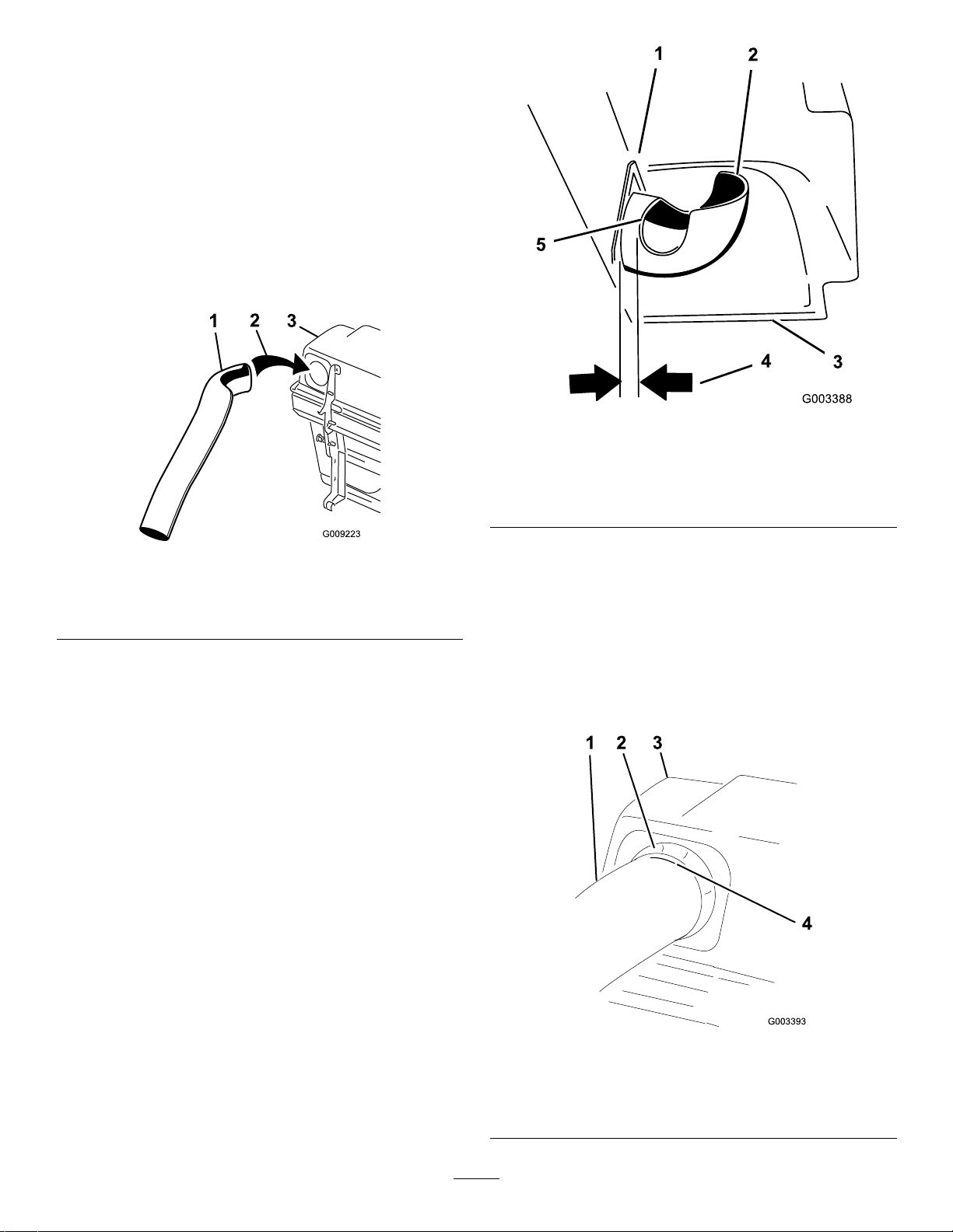
4.Installtheuppertubeintothebaggeropening
andpullitbackoutsothattherubbersealis
protrudingout(Figure19).
g003388
Figure20
Figure19
1.Uppertube3.Baggerhood
2.Baggeropening
5.Measurethedistancethetubeisinsidethe
hood.
Note:Measurefromthehoodplatetotheedge
ofthetubeasshowninFigure20.Thisdistance
needstobe19mm(3/4inch).
1.Hoodplate
2.Uppertube
3.Hoodinthedownposition
g009223
6.Oncethe19mm(3/4inch)measurementhas
4.19mm(3/4inch)
5.Edgeoftube
beenachieved,marktheuppertubeonthe
outsidewheretherubbersealprotrudesout
(Figure21).
Note:Thisismarkedtoensurethecorrect
positionfortheuppertubewhendrillingthe
holesandconnectingtheupperandlowertubes.
Note:Therubbersealmustprotrudeoutfrom
thebaggerhood.
Figure21
1.Uppertube3.Baggerhood
2.Rubbersealprotrudingout4.Markhereagainstthe
rubberseal.
14
g003393

7.Installthelowertubeintotheuppertube(Figure
22).
Figure22
1.Lowertube2.Uppertube
g003424
8.Slidethelowertubeontothebootandlatch
themtogether(Figure23).
Note:Thereisalatchonthetopandbottom
oftheblowerhousing.
g003423
Figure23
1.Blowerassembly3.Latch
2.Lowertube
9.Makesurethatthemowerdeckisinthelowest
height-of-cutpositionandthemarkontheupper
tubeisstillpositionedagainsttheprotruding
rubberseal.
ChecktomakesurethatthemarkfromFigure
21isstillinplace.
15

10.Usingthe3holesorindentationsintheupper
tubeasatemplate,drill3holes(7/32inch
diameter)wheretheupperandlowertubesjoin
together(Figure24).
12.Jointheupperandlowertubeswith3bolts(#10
x3/4inches),3atwashers(7/32inch),and3
locknuts(#10)asshowninFigure25.
Figure24
1.Baggerhood4.Lowertube
2.Uppertube5.Blowerassembly
3.Drill7/32inchdiameter
holeshere(usetheupper
tubeasatemplate)
11.Removethelowertubefromtheblower.
g003392
g003390
1.Lowertube
2.Uppertube
3.Flatwasher(7/32inch)
13.Installthelowertubeontotheblowerhousing
andsecureitwiththelatches.
Figure25
4.Locknut(#10)
5.Bolt,(#10x3/4inches)
10
InstallingtheBeltCover
Partsneededforthisprocedure:
1
Beltcover(fromtheBlowerandDriveKit)
Procedure
1.Lowerthemowerdecktothelowestheight-of-cut
position.
2.Installthenewbeltcoversothatthenotcheson
bothsidesgooverthebelt-coversupportsand
securethelatch(Figure26).
16

Figure26
1.Beltcover5.Latch
2.Blowerassembly6.Beltcovernotch
3.Pulleyassembly7.Beltcoversupport
4.Beltcoverbracket
2.Installplate,nuts(1/2inch)andlockwasher(1/2
inch)undertheframeandweight(Figure27).
3.Repeatforoppositeside.
Note:AllZMastermowersreceivethecaster
weights.
g003370
g001366
Figure27
1.Frontcasterweight4.Nut
2.U-bolt5.Frontcaster
3.Plate6.Lockwasher
11
InstallingtheWeights
Partsneededforthisprocedure:
2
Casterweight(ifneeded)
2U-bolt
4
Nut(1/2inch)
4
Lockwasher(1/2inch)
2Plate
2
Topweight(for60inchmowerdecksonly)
Procedure
TocomplywithANSI/OPEIB71.4-2004Standard,you
mustaddweightstothemachine.
CAUTION
Note:OnlyZMastermowerswith153cm(60
inch)mowerdecksreceivethetopweights.
4.Installthetopweightsontopofeachcaster
weightfor153cm(60inch)mowerswith2bolts
(1/2x2-1/2inches)(Figure28).
Figure28
1.Topweight3.Frontcasterweight
2.Bolt(1/2x2-1/2inches)
4.Frontcasterwheel
g003344
Thebaggeraddsalotofweighttotherear
ofthemachineandmaycauseanunstable
condition,whichcouldresultinalossof
control.
1.Placecasterweightsonthefrontcasters.
17

12
AdjustingtheParking
Brake
NoPartsRequired
Procedure
Checktheparkingbrakeforproperadjustment.
1.Disengagebrakelever(leverdown).
2.Measurethelengthofthespring.
Themeasurementshouldbe70mm(2-3/4inch)
betweenwashers(Figure29).
thecorrectmeasurementisobtained(Figure
29).Tightenjamnutattheyoke.
13
CheckingtheTirePressure
NoPartsRequired
Procedure
Note:Increasethetirepressureduetotheadditional
weight.
Checkandincreasetheairpressureinthefrontcaster
wheelsandthereartires(Figure30).
Pressure:
Reartires:138kPa(20psi)
Frontcasterwheels:172kPa(25psi)
Figure29
1.Brakelever
2.Spring(2-3/4inches/70
mm)
3.Adjustingnuts
4.Collaronbrakerod
3.Ifadjustmentisnecessary,loosenthejamnut
belowthespringandtightenthenutdirectly
belowtheyoke(Figure29).Turnthenutuntil
thecorrectmeasurementisobtained.Tighten
thetwonutstogetherandrepeatonopposite
sideofunit.
4.Turnnutsclockwisetoshortenspringlengthand
turncounter-clockwisetolengthenthespring.
5.Engageparkingbrake,leverup.
6.Measurethedistancebetweenthetrunnionroller
andthecollaronbrakerod.Themeasurement
shouldbe5–7mm(3/16–1/4inch)(Figure29).
7.Ifadjustmentisnecessary,loosenthejamnut
directlybelowtheyoke.Turnthebottomroduntil
5.5–7mm(3/16–1/4inch)
6.Jamnutandyoke
7.Trunnionroller
g003788
g001055
Figure30
18

Operation
Note:Determinetheleftandrightsidesofthe
machinefromthenormaloperatingposition.
Important:Settheparkingbrakewhenyouleave
themachine,evenifjustforafewminutes.
WARNING
Toavoidpersonalinjury,followthese
procedures:
CAUTION
Childrenorbystandersmaybeinjuredifthey
moveorattempttooperatethetractorwhile
itisunattended.
Alwaysremovetheignitionkeyandsetthe
parkingbrakewhenleavingthemachine
unattended,evenifjustforafewminutes.
PositioningtheAdjustable
•Becomefamiliarwithalloperatingand
safetyinstructionsintheOperator's
Manualforyourmachinebeforeusingthis
attachment.
•Neverremovethebaggerorbaggertubes
whiletheengineisrunning.
•Alwaysshuttheengineoffandwaitforall
movingpartstostopbeforeclearingan
obstructionfromthebaggingsystem.
•Neverdomaintenanceorrepairswhilethe
engineisrunning.
•Settheparkingbrake.
WARNING
Withoutthegrassdeector,baggertubesor
completecollectionsystemmountedinplace,
youandothersareexposedtobladecontact
andthrowndebris.Contactwiththerotating
mowerblade(s)andthrowndebriswillcause
injuryordeath.
Bafe
AdjustthebafetopositionB(middleposition)for
bagging.RefertotheOperator’sManualforthe
machineforthebafeadjustmentprocedure.
g000947
Figure31
•Alwaysinstallthegrassdeectorwhen
youremovethecollectionsystemand
changetoside-dischargemode.
•Ifthegrassdeectoriseverdamaged,
replaceitimmediately.Thegrassdeector
routesmaterialdowntowardtheturf.
•Neverputyourhandsorfeetunderthe
mower.
•Nevertrytoclearthedischargeareaor
mowerbladesunlessyoumovethepower
takeoff(PTO)tooffandrotatetheignition
keytooff.Alsoremovethekeyandpull
thewireoffthesparkplug(s).
•T urnofftheenginebeforeuncloggingthe
dischargechute.
•Neveruseyourhandstounclogthe
dischargechute,useastickorsimilar
object.
19

EmptyingtheBagger
1.DisengagethePTOandsettheparkingbrake.
2.Liftthehandletoopenthedoorandemptythe
hopper.
3.Pushthehandledowntoclosethedoor(Figure
32).
Note:Ifthemachineistobedrivenontoa
truckortrailerwiththehopperfull,alwaysback
uptheramp.Thiswillreducethechanceof
rearwardtip.
Figure32
Note:Inmostcases,thedebriscanbeshaken
outofthetubes.
7.Iftheblowerassemblyisplugged,unlatchthe
blowerassembly,removethebelt,andswing
itopen.
8.Useastickorsimilarobject,notyourhands,
toremoveandcleartheobstructionfromthe
blowerassembly.
9.Afteryouremovetheobstruction,install
thecompletecollectionsystemandresume
operation.
RemovingtheBagger
WARNING
Componentsaroundenginewillbehotifthe
machinehasbeenrunning.Touchinghot
g008035
componentscancauseburns.
•Donottouchenginecomponentswhen
theyarehot.
ClearingObstructionsfrom
theCollectionSystem
WARNING
Whenyouoperatecollectionsystem,the
blowerrotatesandcancutofforinjurehands.
•Beforeadjusting,cleaning,repairing
andinspectingtheblower,andbefore
uncloggingthechute,turnofftheengine
andwaitforallmovingpartstostop.
Removethekey.
•Useastick,notyourhands,toremovean
obstructionfromtheblowerandtube.
•Keepface,hands,feet,andanyother
partofyourbodyorclothingawayfrom
concealed,moving,orrotatingparts.
1.DisengagethePTOandsettheparkingbrake.
2.Turnofftheengine,removethekey ,andwait
forallmovingpartstostopbeforeleavingthe
operatingposition.
3.Emptythebagger.
4.Unlatchthelowertube.
5.Removethetubesfromthebagger.
6.Useastickorsimilarobject,notyourhands,to
removeandcleartheobstructionfromthetube
assembly.
•Allowenginetocoolbeforeremovingthe
bagger.
1.DisengagethePTO,settheparkingbrake,and
chockorblockthetires.
2.Turnofftheengine,removethekey ,andwait
forallmovingpartstostopbeforeleavingthe
operatingposition.
3.Unlatchthelowertubefromtheblowerand
removethetubefromtheblowerassembly.
4.Removethetubefromthebaggerhood.
5.Lowerthemowerdecktothelowestheight-of-cut
position.
6.Unlatchthebeltcoveroverthemower-pulley
assembly.
7.Removetheblowerbeltfromthemower-pulley
assembly.
8.Opentheblowerassembly .
9.Removetheblowerassemblyfromthepivot
hole.
10.Ifyouarechangingtoside-dischargemode,
ensurethatthegrassdeectorisinstalledand
canbeloweredintoworkingposition.
11.Removethecollectionsystemassembly.
20

UsingtheGrassDeector
DANGER
(2to3inches)or1/3ofthegrassheight,whichever
isless.Cuttingoffmorethanthiswillreducethe
capacityofthevacuumsystem.
Withoutthegrassdeector,dischargecover,
orcompletegrasscatcherassemblymounted
inplace,youandothersareexposedtoblade
contactandthrowndebris.Contactwith
rotatingmowerblade(s)andthrowndebris
willcauseinjuryordeath.
•Alwaysinstallthegrassdeectorwhen
removingthecollectionsystemand
changingtosidedischargemode.
•Ifthegrassdeectoriseverdamaged,
replaceitimmediately.Thegrassdeector
routesmaterialdowntowardtheturf.
•Neverputyourhandsorfeetunderthe
mower.
•Nevertrytoclearthedischargeareaor
mowerbladesunlessyoumovethepower
takeoff(PTO)totheoffposition,rotatethe
ignitionkeytooffandremovethekey.
TransportingMachines
Donotleavegrassordebrisinthebaggerwhile
transportingthemachineonatrailerortruck.
DANGER
Transportingthemachinewithgrassordebris
inthebaggercandamagethemachine.
Donotleavegrassordebrisinthebagger
whiletransportingthemachineonatraileror
truck.
CuttingFrequency
Cutthegrassoften,especiallywhenitgrowsrapidly .
Youneedtocutyourgrasstwiceifitgetsexcessively
long;refertoBaggingLongGrass(page21).
CuttingTechnique
Forbestlawnappearance,besuretoslightlyoverlap
themowerintothepreviouslycutarea.Thishelps
reducetheloadontheengineandreducesthechance
ofpluggingtheblowerassemblyandtubes.
BaggingSpeed
Thebaggingsystemmayplugifyoudrivetoofastand
theenginespeedgetstooslow.Onhills,youmay
needtoslowthegroundspeedofthemachine.Mow
downhillwheneverpossible.
CAUTION
Asthebaggerlls,extraweightisaddedto
thebackofthemachine.Ifyoustopand
startsuddenlyonhills,youmaylosesteering
controlorthemachinemaytip.
•Donotstartorstopsuddenlywhengoing
uphillordownhill.Avoiduphillstarts.
•Ifyoudostopthemachinewhengoing
uphill,disengagethePTO.Thenbackdown
thehillusingaslowspeed.
•Donotchangespeedsorstoponslopes.
OperatingTips
MachineSize
Rememberthatthemachineislongerandwiderwith
thisattachmentinstalled.Ifyouturntoosharplyin
connedplaces,youmaydamagetheattachmentor
otherproperty.
Trimming
Alwaystrimwiththeleftsideofthemower.Donottrim
withtherightsideofthemowerbecauseyoucould
damagethebaggingtubes.
CuttingHeight
Foroptimumbaggingperformance,setthedeck
height-of-cuttoremovenomorethan51to76mm
BaggingLongGrass
Ifthegrassgrowslongerthannormal,orifitcontains
ahighdegreeofmoisture,raisethecuttingheight
higherthanusualandcutandbagthegrassatthis
setting.Thencutandbagthegrassagainusingthe
lower,normalsetting.
Excessivelylonggrassisheavyandmaynotbe
propelledcompletelyintothebagger.Ifthishappens,
thetubeandblowermayplug.Toavoidplugging
thebaggingsystem,mowthegrassatahigh
height-of-cut,thenlowerthemowertoyournormal
cuttingheightandrepeatthebaggingprocess.
BaggingWetGrass
Ifpossible,alwaystrytocutgrasswhenitisdry.Wet
grasscancauseplugging.
21

ReducingPlugging
Toavoidpluggingthebaggingsystem,reduce
thegroundspeedandmowthegrassatahigh
height-of-cut,thenlowerthemowertoyournormal
cuttingheightandrepeatthebaggingprocess.
SignsofPlugging
Asyouusethebagger,asmallamountofgrass
clippingsnormallyblowoutthefrontofthemower.An
excessiveamountofclippingblow-outindicatesthat
thebaggerisfullorthetubeisplugged.
BaggingBlades
Inmostmowingconditions,thestandardhighlift
bladesprovidesthebestbaggingperformance.
TheT oroAtomicbladeisrecommendedforbagging
leavesindryconditions.Indry,dustyconditions,the
mediumliftorlowliftbladesreducesdustanddirt
blowoutwhileprovidingeffectivebaggingairow.
ContactanAuthorizedServiceDealerfortheproper
bladesfordifferentmowingconditions.
CurbClimbingandLoading
Alwaysliftthedecktothehighestpositionwhenloading
themachineontrailersorascending/descendinga
curb.Leavingthemowerinalowerpositionwhile
loadingorgoingoveracurbcancausedamagetothe
mower.Ifacurbishigherthan152mm(6inches),
crossitatasharpanglewiththedeckfullyraised.
Useextremecautionwhenloadingontoatrailer.Use
afull-widthramp;therampshouldbelongenoughso
thattheangledoesnotexceed15degrees.
22

Maintenance
RecommendedMaintenanceSchedule(s)
MaintenanceService
Interval
Aftertherst8hours
Beforeeachuseordaily
Every25hours
Every50hours
Every100hours
MaintenanceProcedure
•Inspecttheblowerbelt.
•Inspectthecollectionsystem.
•Cleanthehoodscreen.
•Cleanthecollectionsystem.
•Inspecttheblowerbelt.
•Greasetheidlerarm.
•Greasethehandlepivot.
•Inspectthecollectionsystem.
CleaningtheBaggerScreen
ServiceInterval:Beforeeachuseordaily
Cleanthescreenbeforeeachuse(moreofteninwet
grass).
1.Disengagethepowertakeoff(PTO)andsetthe
parkingbrake.
2.Turnofftheengine,removethekey ,andwait
forallmovingpartstostopbeforeleavingthe
operatingposition.
3.Openthebagger.
4.Cleanthedebrisfromthescreen.
5.Closethebagger.
ReplacingtheBlowerBelt
1.DisengagethePTO,movethemotion-control
leverstotheNEUTRAL-LOCKEDposition,andset
theparkingbrake.
2.Stoptheengine,removethekey,andwait
forallmovingpartstostopbeforeleavingthe
operatingposition.
3.Pullbackonthespring-loadedidlerpulleyto
relievethebelttension(Figure33).
4.Removetheexistingbaggerbeltfromthe
mower-deckpulleyandthentheblowerpulleys.
5.Installthenewbeltaroundtheblowerpulleys
andthemower-deckpulley(Figure33).
CleaningtheCollection
System
ServiceInterval:Beforeeachuseordaily
1.Washtheinsideandoutsideofthebaggerhood,
tube,andtheundersideofthemower.Usea
mildautomotivedetergenttoremovedirt.
2.Makesureyouremovemattedgrassfromall
parts.
3.Afterwashingallparts,letthemdrythoroughly.
Note:Withallpartsinstalled,startandrunthe
machineforaminutetoassistindrying.
InspectingtheBlowerBelt
ServiceInterval:Aftertherst8hours
Every25hours
Checkthebeltsforcracks,frayededges,burnmarks,
oranyotherdamage.Replacedamagedbelts.
Figure33
1.Idlerpulley4.Peg
2.Mower-deckpulley5.Belt
3.Spring
g003398
6.Blowerpulley
23

6.InstallthespringasshowninFigure34.
Figure34
GreasingtheIdlerArmand
HandlePivot
ServiceInterval:Every50hours—Greasetheidler
arm.
Every100hours—Greasethehandlepivot.
Greasetheblowerbeltidlerarm(Figure36).
g003638
1.Spring-loadedidlerpulley
2.Short-hookend
3.Long-hookend
7.Pullbackonthespring-loadedidlerpulleyand
installthebeltontothespring-loadedidlerpulley
(Figure33).
CheckingandAdjustingthe
BlowerLatch
Closetheblowerassemblytoseeifthelatchesare
adjustedcorrectly.Loosenortightentheboltssothe
latchesrmlyholdtheblowerassemblyagainstthe
mowerdeckbutcanbereleasedbyhand.
g003455
Figure36
Greasethehandlepivot(Figure37).
Figure35
1.Latch3.Blowerassembly
2.Bolt
g003400
g009229
Figure37
24

InspectingtheCollection
System
ServiceInterval:Aftertherst8hours
Every100hours
1.DisengagethePTO,movethemotion-control
leverstotheNEUTRAL-LOCKEDposition,andset
theparkingbrake.
2.Stoptheengine,removethekey,andwait
forallmovingpartstostopbeforeleavingthe
operatingposition.
3.Checktheuppertube,lowertube,bagger,and
theblowerassembly.
Note:Replacethesepartsiftheyarecracked
orbroken.
4.Checkthebaggerframe.
Note:Replaceanypartsthatarecrackedor
broken.
5.Tightenallnutsboltsandscrews.
AdjustingtheDoorClosing
Thetwohingelinksandtwostopscrewscanbe
adjustedtoprovidecompleteclosingofthedoor.
1.DisengagethePTO,movethemotion-control
leverstotheNEUTRAL-LOCKEDposition,andset
theparkingbrake.
2.Stoptheengine,removethekey,andwait
forallmovingpartstostopbeforeleavingthe
operatingposition.
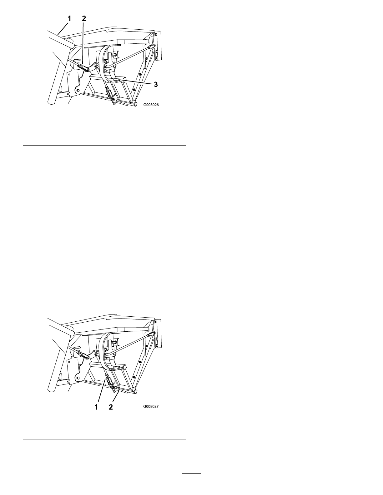
3.Withthedoorclosed,loosenthenutsandadjust
thestopboltssothatthecontactarmisstraight
upanddown(Figure38andFigure39).
1.Contactarm—straightup
anddown
2.Stopbolt
1.Contactarm
2.Stopbolt
g008022
Figure38
3.Hingelinks
g008023
Figure39
3.Hingelinks
4.Adjustthelengthofthehingelinkstosothatthe
doorcompletelyclosesandreasonableforceis
onthehandle(Figure38andFigure39).
Note:Lengthenthelinkstoreducetheforce.
Shortenthelinkstoincreasetheforce
Note:Makesurethatboththeleftandright
sidesareadjustedthesamedistance.Withthe
doorclosed,thelinksshouldbeslightlytightto
minimizerattling.
5.Tightenthenuts.
AdjustingtheDoorOpening
Note:Performthisprocedureafteradjustingthedoor
tocompletelyclose.
Adjustthehandlelinktosothatthedooropensas
muchaspossible(Figure40).
Note:Lengthenthehandlelinktoopenthedoor
farther.Shortenthehandlelinktoopenthedoorless
Note:Howfarthedooropensiscontrolledbythe
contactarmhittingthestop.Thestopisnotadjustable
andpreventsthedoorfrombeingopenedtoofar.
25
InspectingtheMower
Blades
1.Inspectthemowerbladesregularlyand
wheneverabladestrikesaforeignobject.
2.Ifbladesarebadlywornordamaged,installnew
blades.RefertoyourmowerOperator'sManual
forcompleteblademaintenance.
Figure40
1.Handle
2.Handlelink
3.Stop
AdjustingtheLatches
Note:Adjusttheopendoorandcloseddoorpositions
beforeadjustingthelatches.
1.DisengagethePTO,movethemotion-control
leverstotheNEUTRAL-LOCKEDposition,andset
theparkingbrake.
2.Stoptheengine,removethekey,andwait
forallmovingpartstostopbeforeleavingthe
operatingposition.
3.Closethedoor.
4.Ensurethatthelatchescompletelyengageand
contactsthelatchrodweldedtothedoor(Figure
41).
g008026
InstallingtheMowerBlades
Inmostmowingconditions,thestandardhigh-lift
bladeswillprovidethebestbaggingperformance.
TheT oroAtomicbladeisrecommendedforbagging
leavesindryconditions.Indrydustyconditions,the
medium-liftorlow-liftbladesreducesdustanddirt
blowoutwhileprovidingeffectivebaggingairow.
ContactanAuthorizedServiceDealerfortheproper
bladesfordifferentmowingconditions.
RefertothemowerOperator'sManualformore
informationoninstallingblades.
Note:Thelatchesneedtobetightagainstthe
latchrod.Theyneedtobelooseenoughto
moveorwiggle.
Figure41
1.Latchlink2.Latchrod
g008027
26

InstallingtheGrass
Deector
WARNING
Anuncovereddischargeopeningcouldallow
thelawnmowertothrowobjectsatyouor
othersandresultinseriousinjury.Also,
contactwiththebladecouldoccur.
•Neveroperatethelawnmowerunlessyou
installacoverplate,amulchplate,ora
grasschuteandcatcher.
•Makesurethatthegrassdeectorisinthe
downposition.
1.Removethelocknut,bolt,springandspacer
holdingthedeectortothepivotbrackets
(Figure42).
2.Removethedamagedorworngrassdeector.
3.Placethespacerandspringontothegrass
deector.
Figure42
1.Bolt
2.Spacer6.GrassDeector
3.Locknut
4.Spring8.J-hookendofspring
5.Springinstalled
7.Lendofspring,place
behinddeckedgebefore
installingbolt
g002519
Note:PlacetheLendofthespringbehindthe
deckedge.
Note:MakesurethattheLendofthespringis
installedbehindthedeckedgebeforeinstalling
theboltasshowninFigure42
4.Installtheboltandnut.
5.PlacetheJ-hookendofthespringaroundthe
grassdeector(Figure42).
Important:Thegrassdeectormustbeable
tolowerdownintoposition.Liftthedeector
uptotestthatitlowersintothefulldown
position.
27

Storage
1.Cleanthebagger.RefertoCleaningtheBagger
Screen(page23)andCleaningtheCollection
System(page23).
2.Inspectthebaggerfordamage.Referto
InspectingtheCollectionSystem(page25).
3.Makesurethatthebaggerisemptyand
thoroughlydry.
4.Checkthebeltforwearorcracks.
5.Storethemachineinaclean,dryplace,outof
directsunlight.Ifyoumuststorethemachine
outside,coveritwithaweatherproofcover.This
protectstheplasticpartsandextendsthelifeof
themachine.
28

Troubleshooting
Problem
Thereisabnormalvibration.
Baggingperformanceisreduced.
Blowerandtubesplugtoofrequently .
PossibleCauseCorrectiveAction
1.Cuttingblade(s)is/arebentor
unbalanced.
2.Ablade-mountingboltisloose.2.Tightentheblade-mountingbolt.
3.Ablowerpulleyorpulleyassemblyis
loose.
4.Ablowerbeltisworn.4.Replacetheblowerbelt.
5.Blowerfanblade(s)is/arebentor
unbalanced.
1.Theenginespeedislow.1.Alwaysoperatethecollectionsystem
2.Thescreeninthebaggerhoodis
plugged.
3.Ablowerbeltisloose.3.Replacetheblowerbelt.
4.Atubeorblowerisplugged.4.Locateandremovethepluggeddebris.
5.Thebaggerisfull.
1.Thebaggeristoofull.1.Dumpthebaggermorefrequently.
2.Theenginespeedislow.2.Alwaysoperatethecollectionsystem
3.Grassistoowet.3.Cutgrasswhenitisdry.
4.Grassistoolong.4.Cutnomorethan51-76mm(2-3
5.Thescreeninthebaggerhoodis
plugged.
6.Thegroundspeedistoofast.6.Drivesloweratfullthrottle.
7.Ablowerbeltisworn.7.Replacetheblowerbelt.
1.Installnewcuttingblade(s).
3.Tightentheappropriatepulley.
5.ContactanAuthorizedServiceDealer.
atfullthrottle.
2.Removedebris,leavesorgrass
clippingsfromthescreen.
5.Emptythebagger.
atfullthrottle.
inches)or1/3ofthegrassheight,
whicheverisless.
5.Removedebris,leavesorgrass
clippingsfromthescreen.
Debrisblowout.
Theblowerimpellerdoesnotspinfreely.
1.Thebaggeristoofull.1.Dumpthebaggermorefrequently.
2.Thegroundspeedistoofast.2.Drivesloweratfullthrottle.
3.Themowerdeckisnotlevel.
1.Theblowerisplugged.1.Removedebris,leavesorgrass
2.Theimpellernotaligned.
3.SeetheOperator'sManualforthe
machineforlevelingthemowerdeck.
clippingsfromtheblowerimpeller .
2.ContactanAuthorizedServiceDealer.
29

Notes:

Notes:

TheToroTotalCoverageWarranty
ALimitedWarranty(seewarrantyperiodsbelow)Contractor
Landscape
Equipment
(LCE)
ConditionsandProductsCovered
TheToroCompanyanditsafliate,ToroWarrantyCompany ,pursuanttoanagreement
betweenthem,jointlypromisetotheoriginalpurchasertorepairtheToroProducts
listedbelowifdefectiveinmaterialsorworkmanship.
Thefollowingtimeperiodsapplyfromthedateofpurchasebytheoriginalowner:
ProductsWarrantyPeriod
21in.Mowers2yearsResidentialUse
1yearCommercialUse
4
•Engines
Honda–2years
Kawasaki–3years
30in.Mowers2yearsResidentialUse
1yearCommercialUse
4
•Engines
Mid-SizeWalk-BehindMowers
4
•Engines
GrandStand
4
•Engines
•Frame
®
ZMaster
•Engines
2000SeriesMowers
4
•Frame
®
ZMaster
•Engines
•Frame
ZMaster
•Engines
®
4
4
3000SeriesMowers
5000SeriesMowers
®
Mowers
Kawasaki–3years
2years
Kawasaki–3years
5yearsor1,200hours
3years
Lifetime(originalowneronly)
4yearsor500hours
3years
Lifetime(originalowneronly)
5yearsor1,200hours
3years
Lifetime(originalowneronly)
5yearsor1,200hours
KohlerCommand–2years
KohlerEFI–3years
•Frame
®
ZMaster
•Engines
6000SeriesMowers
4
•Frame
®
ZMaster
•Engines
7000SeriesMowers
4
•Frame
®
ZMaster
•Engines
8000SeriesMowers
4
•Frame
Lifetime(originalowneronly)
5yearsor1,200hours
Kawasaki–3years
Lifetime(originalowneronly)
5yearsor1,200hours
2years
Lifetime(originalowneronly)
2yearsor1,200hours
2years
Lifetime(originalowneronly)
AllMowers
•Battery90daysPartsandLabor
1yearPartsonly
•BeltsandTires90days
•Attachments1year
1
Residentialusemeansuseoftheproductonthesamelotasyourhome.Useatmorethanone
locationisconsideredcommercialuseandthecommercialwarrantywouldapply.
2
Whicheveroccursrst.
3
LifetimeFrameW arranty-Ifthemainframe,consistingofthepartsweldedtogethertoformthe
tractorstructurethatothercomponentssuchastheenginearesecuredto,cracksorbreaksin
normaluse,itwillberepairedorreplaced,atT oro'soption,underwarrantyatnocostforpartsand
labor.Framefailureduetomisuseorabuseandfailureorrepairrequiredduetorustorcorrosion
arenotcovered.
4
SomeenginesusedonT oroProductsarewarrantedbytheenginemanufacturer.
1
1
2
3
2
3
2
3
2
3
2
3
2
3
2
3
InstructionsforObtainingWarrantyService
IfyouthinkthatyourToroProductcontainsadefectinmaterialsorworkmanship,
followthisprocedure:
1.ContactanyAuthorizedToroServiceDealertoarrangeserviceattheir
dealership.T olocateadealerconvenienttoyou,refertotheY ellowPagesof
yourtelephonedirectory(lookunder“LawnMowers”)oraccessourwebsite
atwww.Toro.com.Youmayalsocallthenumberslistedinitem#3tousethe
24-hourT oroDealerlocatorsystem.
2.Bringtheproductandyourproofofpurchase(salesreceipt)totheService
Dealer.Thedealerwilldiagnosetheproblemanddetermineifitiscovered
underwarranty.
3.IfforanyreasonyouaredissatisedwiththeServiceDealer’sanalysisorwith
theassistanceprovided,contactusat:
RLCCustomerCareDepartment
ToroWarrantyCompany
811 1LyndaleAvenueSouth
Bloomington,MN55420-1 196
888-865-5676(U.S.Customers)
888-865-5691(Canadacustomers)
OwnerResponsibilities
YoumustmaintainyourToroProductbyfollowingthemaintenanceprocedures
describedintheOperator'sManual.Suchroutinemaintenance,whetherperformedby
adealerorbyyou,isatyourexpense.
ItemsandConditionsNotCovered
Thereisnootherexpresswarrantyexceptforspecialemissionsystemcoverage
andenginewarrantycoverageonsomeproducts.Thisexpresswarrantydoesnot
coverthefollowing:
•Costofregularmaintenanceserviceorparts,suchaslters,fuel,lubricants,oil
changes,sparkplugs,airltersbladesharpeningorwornblades,cable/linkage
adjustments,orbrakeandclutchadjustments
•Componentsfailingduetonormalwear
•Anyproductorpartwhichhasbeenalteredormisusedorneglectedandrequires
replacementorrepairduetoaccidentsorlackofpropermaintenance
•Pickupanddeliverycharges
•RepairsorattemptedrepairsbyanyoneotherthananAuthorizedToroService
Dealer
•Repairsnecessaryduetofailuretofollowrecommendedfuelprocedure(consult
Operator'sManualformoredetails)
–Removingcontaminantsfromthefuelsystemisnotcovered
–Useofoldfuel(morethanonemonthold)orfuelwhichcontainsmorethan
10%ethanolormorethat15%MTBE
–Failuretodrainthefuelsystempriortoanyperiodofnon-useoverone
month
GeneralConditions
AllrepairscoveredbythesewarrantiesmustbeperformedbyanAuthorizedToro
ServiceDealerusingT oroapprovedreplacementparts.
NeitherTheToroCompanynorToroWarrantyCompanyisliableforindirect,
incidentalorconsequentialdamagesinconnectionwiththeuseoftheToro
Productscoveredbythiswarranty,includinganycostorexpenseofproviding
substituteequipmentorserviceduringreasonableperiodsofmalfunctionor
non-usependingcompletionofrepairsunderthiswarranty .
Allimpliedwarrantiesofmerchantability(thattheproductistforordinaryuse)
andtnessforuse(thattheproductistforaparticularpurpose)arelimitedto
thedurationoftheexpresswarranty .
Somestatesdonotallowexclusionsofincidentalorconsequentialdamages,
orlimitationsonhowlonganimpliedwarrantylasts,sotheaboveexclusions
andlimitationsmaynotapplytoyou.
Thiswarrantygivesyouspeciclegalrights,andyoumayalsohaveotherrights
whichvaryfromstatetostate.
CountriesOtherthantheUnitedStatesorCanada
CustomerswhohavepurchasedT oroproductsoutsidetheUnitedStatesorCanadashouldcontacttheirT oroDistributor(Dealer)toobtainguaranteepoliciesforyourcountry ,
province,orstate.IfforanyreasonyouaredissatisedwithyourDistributor'sserviceorhavedifcultyobtainingguaranteeinformation,contacttheT oroimporter .Ifallother
remediesfail,youmaycontactusatToroWarrantyCompany.
AustralianConsumerLaw:AustraliancustomerswillnddetailsrelatingtotheAustralianConsumerLaweitherinsidetheboxoratyourlocalToroDealer.
374-0252RevG
 Loading...