

Page 1

FormNo.3359-401RevA
60inand72inDFSE-ZVac
CollectionSystem
Z500SeriesZMasterMowers
ModelNo.78544—SerialNo.280000001andUp
ModelNo.78545—SerialNo.280000001andUp
Registeratwww.T oro.com.OriginalInstructions(EN)
Page 2
Introduction
Readthisinformationcarefullytolearnhowtooperate
andmaintainyourproductproperlyandtoavoidinjury
andproductdamage.Youareresponsibleforoperating
theproductproperlyandsafely.
YoumaycontactTorodirectlyatwww.Toro.comfor
productandaccessoryinformation,helpndinga
dealer,ortoregisteryourproduct.
Wheneveryouneedservice,genuineToroparts,or
additionalinformation,contactanAuthorizedService
DealerorToroCustomerServiceandhavethemodel
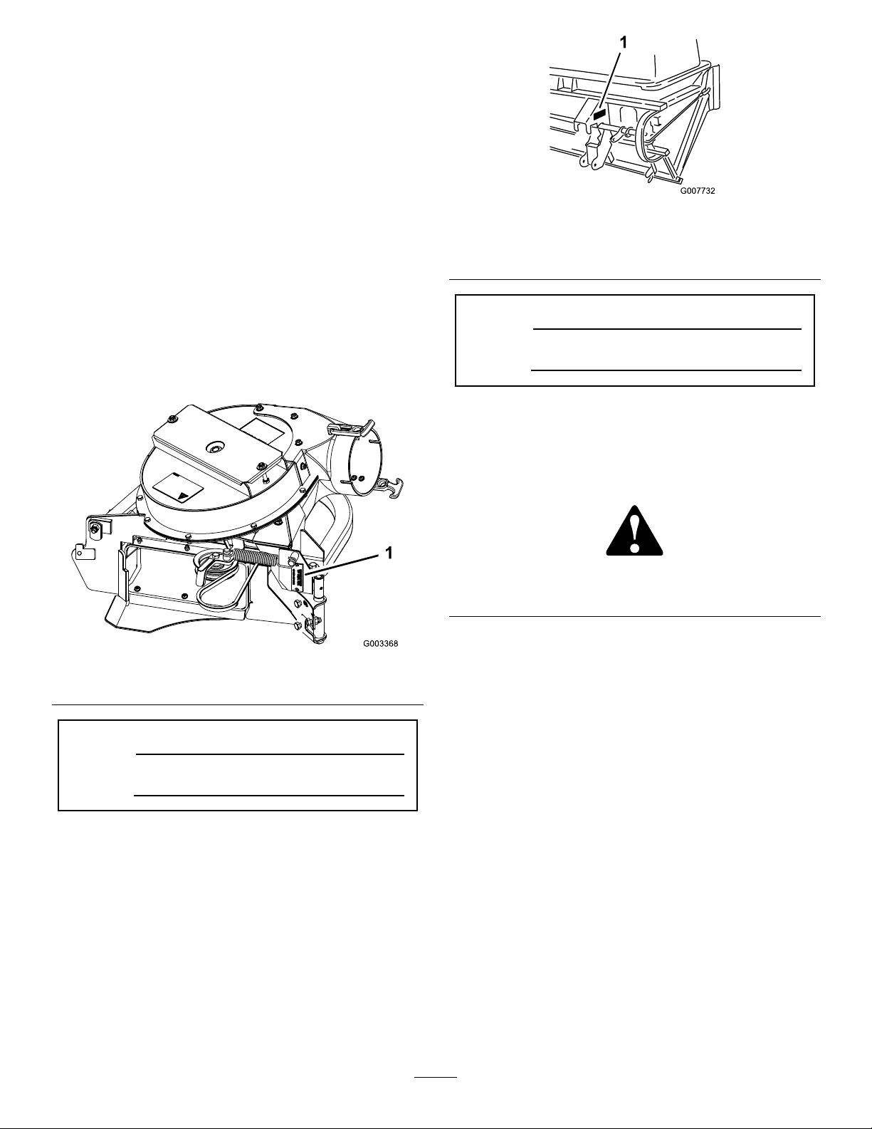
andserialnumbersofyourproductready .Figure1
andFigure2identiesthelocationofthemodeland
serialnumbersontheproduct.Writethenumbersin
thespaceprovided.
Figure2
BaggerSerialNumber
1.Baggermodelandserialnumberlocation
ModelNo.
SerialNo.
Thismanualidentiespotentialhazardsandhas
safetymessagesidentiedbythesafetyalertsymbol
(Figure3),whichsignalsahazardthatmaycauseserious
injuryordeathifyoudonotfollowtherecommended
precautions.
Figure3
1.Safetyalertsymbol
Figure1
1.Blowermodelandserialnumberlocation
ModelNo.
SerialNo.
Thismanualuses2otherwordstohighlightinformation.
Importantcallsattentiontospecialmechanical
informationandNoteemphasizesgeneralinformation
worthyofspecialattention.
Contents
Introduction.................................................................2
Safety...........................................................................3
SafetyandInstructionalDecals.............................4
Setup............................................................................5
1PreparingtheMower.........................................6
2InstallingtheBaggerMountingBracket..............6
3InstallingtheHandleAssembly..........................8
4TighteningallMountingBolts............................9
5InstallingtheBaggerAssembly...........................9
6RoutingtheBlowerBeltintotheBlower
Assembly.......................................................10
7InstallingtheBlowerAssembly.........................10
8SizingtheUpperTubefor60inchMowers
withGasEngines...........................................12
©2008—TheToro®Company
8111LyndaleAvenueSouth
Bloomington,MN55420
Contactusatwww.Toro.com.
2
PrintedintheUSA.
AllRightsReserved
Page 3

9InstallingtheDischargeTubes..........................13
10InstallingtheBeltCover.................................15
11InstallingtheW eights.....................................16
12AdjustingtheParkingBrake...........................16
13CheckingtheTirePressure.............................17
Operation...................................................................18
PositioningtheAdjustableBafe........................18
EmptyingtheBagger..........................................19
ClearingObstructionsfromtheCollection
System............................................................19
RemovingtheBagger.........................................19
UsingtheGrassDeector...................................20
TransportingMachines.......................................20
OperatingTips...................................................20
Maintenance...............................................................22
RecommendedMaintenanceSchedule(s)................22
CleaningtheBaggerScreen.................................22
CleaningtheCollectionSystem...........................22
InspectingtheBlowerBelt..................................22
ReplacingtheBlowerBelt...................................22
CheckingandAdjustingtheBlower
Latch..............................................................23
GreasingtheIdlerArmandHandle
Pivot..............................................................23
InspectingtheCollectionSystem........................24
AdjustingtheDoorClosing................................24
AdjustingtheDoorOpening..............................25
AdjustingtheLatches.........................................25
InspectingtheMowerBlades..............................25
InstallingtheMowerBlades................................25
InstallingtheGrassDeector.............................26
Storage.......................................................................26
Troubleshooting.........................................................27
Safety
Thefollowinglistcontainssafetyinformationspecic
toToroproductsandothersafetyinformationyoumust
know .
•Becomefamiliarwiththesafeoperationofthe
equipment,withtheoperatorcontrols,andsafety
signs.
•Useextracarewithgrasscatchersorother
attachments.Thesecanchangetheoperating
characteristicsandthestabilityofthemachine.
•Followthemanufacturer’srecommendationsfor
addingorremovingwheelweightsorcounterweights
toimprovestability .
•Donotuseagrasscatcheronsteepslopes.Aheavy
grasscatchercouldcauselossofcontroloroverturn
themachine.
•Slowdownanduseextracareonhillsides.Besure
totravelintherecommendeddirectiononhillsides.
Turfconditionscanaffectthemachine’sstability.
Useextremecautionwhileoperatingneardrop-offs.
•Keepallmovementonslopesslowandgradual.Do
notmakesuddenchangesinspeed,directionsor
turning.
•Thegrasscatchercanobstructtheviewtotherear.
Useextracarewhenoperatinginreverse.
•Usecarewhenloadingorunloadingthemachine
intoatrailerortruck.Ifthemachineistobedriven
ontoatruckortrailerwiththehopperfull,always
backuptheramp.
•Neveroperatewiththedischargedeectorraised,
removedoraltered,unlessusingagrasscatcher.
•Keephandsandfeetawayfrommovingparts.Do
notmakeadjustmentswiththeenginerunning.
•Stoponlevelground,disengagedrives,chockor
blockwheels,shutoffenginebeforeleavingthe
operator’spositionforanyreasonincludingemptying
thegrasscatcheroruncloggingthechute.
•Ifyouremovethegrasscatcher,besuretoinstallany
dischargedeectororguardthatmighthavebeen
removedtoinstallthegrasscatcher.Donotoperate
themowerwithouteithertheentiregrasscatcheror
thegrassdeectorinplace.
•Stoptheenginebeforeremovingthegrasscatcher
oruncloggingthechute.
•Donotleavegrassingrasscatcherforextended
periodsoftime.
•Grasscatchercomponentsaresubjecttowear,
damageanddeterioration,whichcouldexpose
movingpartsorallowobjectstobethrown.
3
Page 4
Frequentlycheckcomponentsandreplacewith
manufacturer’srecommendedparts,whennecessary.
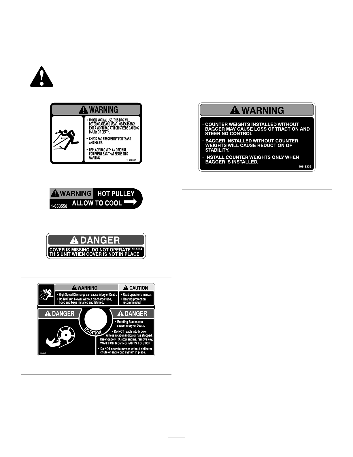
SafetyandInstructionalDecals
Safetydecalsandinstructionsareeasilyvisibletotheoperatorandarelocatednearanyareaof
potentialdanger.Replaceanydecalthatisdamagedorlost.
1-653554
106-3339
1-653558
98-5954
103-3507
4
Page 5

Setup
LooseParts
Usethechartbelowtoverifythatallpartshavebeenshipped.
ProcedureDescription
1
2
3
4
5
6
7
8
9
Nopartsrequired
Baggermountingbracket1
Baggersideplate2
Spacer
Bolt,(3/8x1-1/2inches)
Bolt,(3/8x1inch)(forZ593mowers
only)
FlangeNut,(3/8inch)
Curvedwasher
Handleassembly1
Washer2
Bolt(3/8x1-1/4inches)
Clevispinspring
Locknut(3/8inch)
Nopartsrequired
Baggerassembly1
Clevispin
Hairpincotter2
Blowerbelt(fromBlowerandDriveKit)
Blowerassembly(fromBlowerand
DriveKit)
Spring(fromBlowerandDriveKit)
Uppertube1
Uppertube1
Lowertube1
Bolt,(#10x3/4inches)
Locknut,(#10)
Washer,(7/32inch)
Qty.
14
14
14
Use
–
2
2
3
1
3
–
2
1
1
1
3
3
3
Preparethemower.
Installthebaggermountingbracket
Installthehoodassembly.
Tightenallmountingbolts
Installthebaggerassembly.
Routetheblowerbeltintotheblower
assembly.
Installtheblowerassembly.
Sizetheuppertubefor60inchmowers
withgasengines.
Installthedischargetubes.
10
11
Beltcover(fromBlowerandDriveKit)
Casterweight
U-bolt2
Nut,(1/2inch)
Lockwasher,(1/2inch)
Plate2
Topweight(for60inchmowerdecks
only)
5
2
4
4
2
2
Installthebeltcover .
Installtheweights.
Page 6

ProcedureDescription
Qty.
Use
12
13
Note:Determinetheleftandrightsidesofthemachinefromthenormaloperatingposition.
Nopartsrequired
Nopartsrequired
1
PreparingtheMower
InstallingtheBaggerMounting
–
–
2
Bracket
NoPartsRequired
Partsneededforthisprocedure:
Procedure
Performthefollowingproceduretopreparethemower
forattachingtheblowerandnishingkit.
1.DisengagethePTO,movethemotioncontrollevers
totheneutrallockedpositionandsettheparking
brake.
2.Stoptheengine,removethekey,andwaitforall
movingpartstostopbeforeleavingtheoperating
position.
3.Repairallbentordamagedareasofmowerdeckand
replaceanymissingparts.
4.Cleanthemowerofanydebrisonthedeckorrear
partofthemowertoeaseinstallation.
1Baggermountingbracket
2Baggersideplate
2
Spacer
14
Bolt,(3/8x1-1/2inches)
2
Bolt,(3/8x1inch)(forZ593mowersonly)
14
FlangeNut,(3/8inch)
14
Curvedwasher
Procedure
Important:Donottightenanyboltsuntilbothside
bracketsandbaggermountingbracketaretloose
onthemachine.
RefertoTighteningtheMountingBoltsforthe
correctproceduretotightenthebolts.
Adjusttheparkingbrake.
Checkthetirepressure.
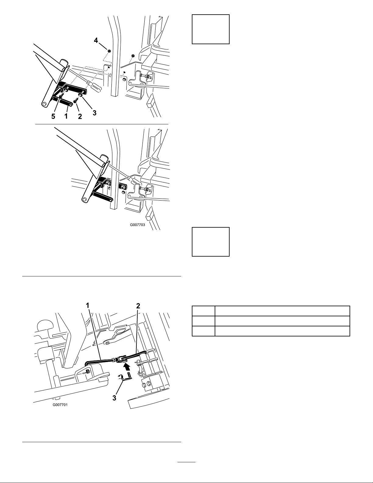
1.Removethebolts,nuts,andwashersholdingtheroll
bartoonesideofthemachine.Discardthenuts,
bolts,andwashers(Figure4,Figure5,andFigure6).
2.Installthebaggersideplateandtherollbarsection
tothesideofthemachineusing4bolts(3/8x1-1/2
inches),4curvedwashers(3/8inch),and4ange
nuts(3/8inch)(Figure4,Figure5,andFigure6).
3.Repeatthestepsabovefortheoppositeside
(Figure4,Figure5,andFigure6).
Note:Makesurethecurvedwashersareinstalledas
showninFigure4,Figure5,andFigure6.
4.Installthebaggermountingbrackettotheleftand
rightsidebaggerbracketswith4bolts(3/8x1-1/2
inches),4curvedwashers(3/8inch),and4ange
nuts(3/8inch)(Figure4,Figure5,andFigure6).
5.Installthebaggermountingbrackettotherearframe
ofthemachinewith2bolts(3/8x1-1/2inches)(use
6
Page 7
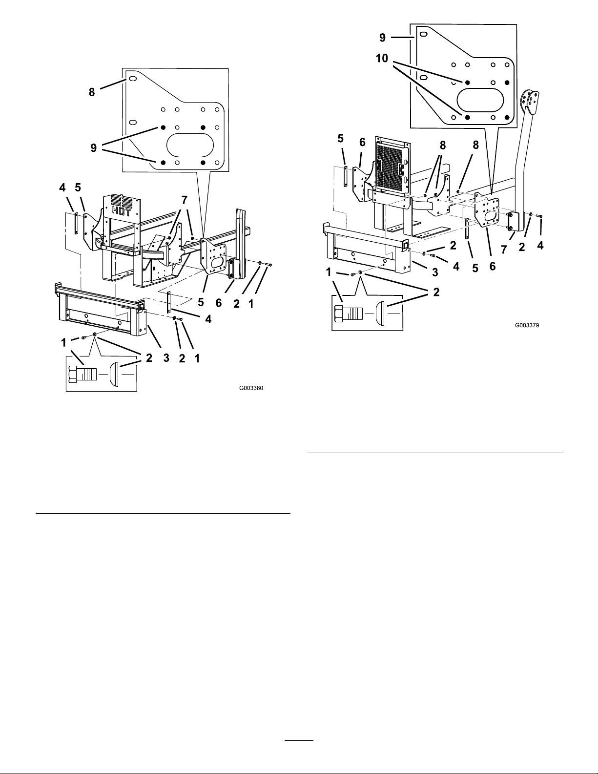
2bolts(3/8x1inch)forZ593mowersasshownin
Figure5),2curvedwashers(3/8inch),and2ange
nuts(3/8inch)(Figure4,Figure5,andFigure6).
Figure4
ForZ500GasMowers
1.Bolt,(3/8x1-1/2inches)6.ROPS
2.Curvedwasher,(3/8inch)7.Flangenut,(3/8inch)
3.Baggermountingbracket
4.Spacer
5.Baggersideplate
8.Sideviewofbaggerside
plate
9.Holestowheninstalling
thesidebracket
Figure5
ForKubotaDieselMowers
1.Bolt,(3/8x1inch)
2.Curvedwasher,(3/8inch)7.ROPS
3.Baggermountingbracket
4.Bolt,(3/8x1-1/2inches)9.Sideviewofbaggerside
5.Spacer
6.Baggersideplate
8.Flangenut,(3/8inch)
plate
10.Holestowheninstalling
thesidebracket
7
Page 8
3
InstallingtheHandleAssembly
Partsneededforthisprocedure:
1Handleassembly
2Washer
3
Bolt(3/8x1-1/4inches)
1
Clevispinspring
3
Locknut(3/8inch)
Procedure
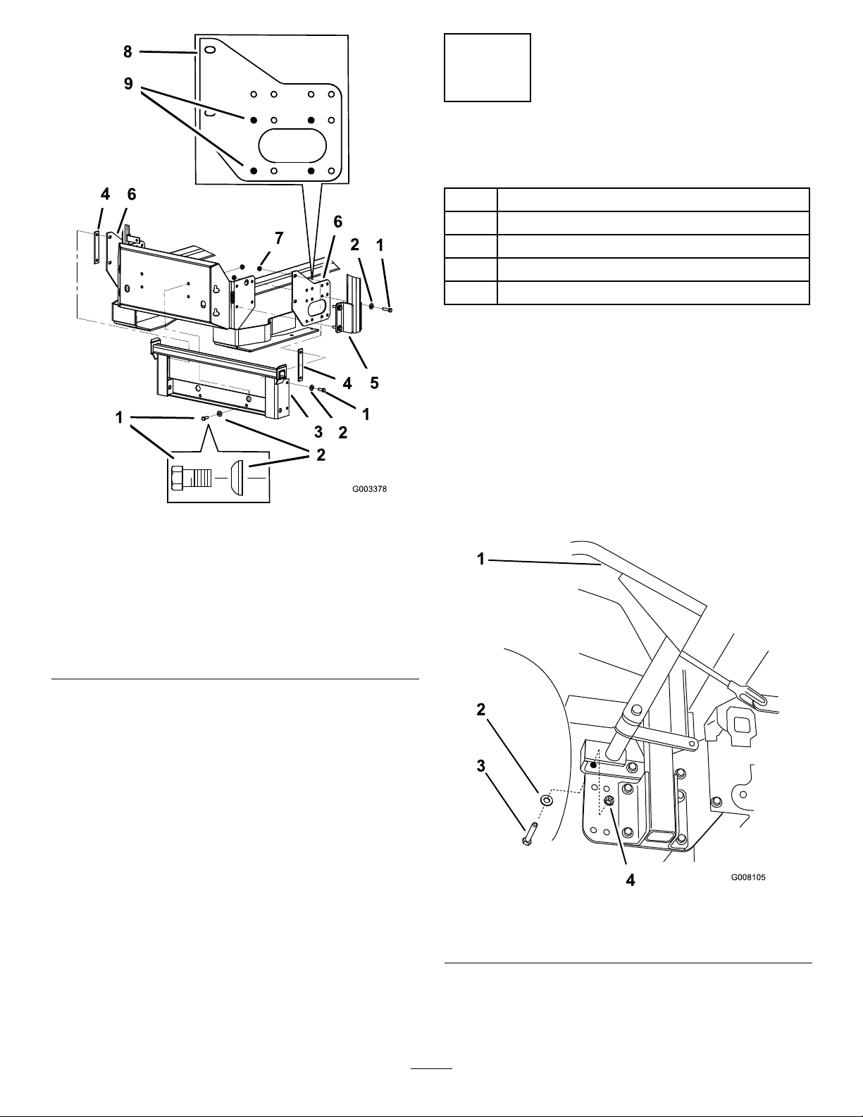
1.PositionthehandleassemblybetweentheROPSroll
barandthebaggermountingbracket(Figure8).
2.Installthehandleassemblytothebaggermounting
bracketandthemachinewith3bolts(3/8x1-1/4
inches)and3locknuts(3/8inch)(Figure7and
Figure8).
Figure6
ForDaihatsuDieselMowers
1.Bolt,(3/8x1-1/2inches)6.ROPS
2.Curvedwasher,(3/8inch)7.Flangenut,(3/8inch)
3.Baggermountingbracket
4.Spacer
5.Baggersideplate
8.Sideviewofbaggerside
plate
9.Holestowheninstalling
thesidebracket
Note:ThemiddleboltisnotusedonKubota
poweredengines(Figure8).
Figure7
1.Handleassembly
2.Washer
3.Bolt(3/8x1-1/4inches)
4.Nut(3/8inch)
8
Page 9
4
TighteningallMountingBolts
NoPartsRequired
Procedure
Thefollowingstepsarethecorrectsequencetotighten
thesidebracketsandthebaggermountingbracket.All
mountingboltsneedtobetorquedto35ft-lb(48N⋅m).
1.Tightenthebaggermountingbrackettotherear
framerst.
2.TightentheROPSandsidebracketstothesideof
themower.
3.Ifthebaggermountingbracketmovessidetosidean
1/8inchormore,installoneorbothofthespacers
betweenthebaggermountingbracketandmounting
plates(Figure4,Figure5,andFigure6).
4.Tightenthebaggermountingbrackettotheside
brackets.
Figure8
1.Handleassembly
2.Bolt(3/8x1-1/4inches)
3.Washer
3.Installthebaggerarmlinkagetothebaggerassembly
withaclevispinspring(Figure9).
4.Nut(3/8inch)
5.Thisboltisnotusedon
Kubotapoweredmachines
5
InstallingtheBagger
Assembly
Partsneededforthisprocedure:
1Baggerassembly
2
Clevispin
2Hairpincotter
Procedure
1.Installthebaggerassemblyontothebagger
mountingbracket(Figure10).
2.Installthe2clevispinsintothebaggerassemblyand
baggermountingbracket.Secureitwith2hairpin
cotters(Figure10).
1.Baggerarmlink
2.Baggerassembly
Figure9
3.Clevispinspring
9
Page 10

Figure10
1.Hoodassembly3.Hairpincotter
2.Clevispin
4.Baggermountingbracket
6
RoutingtheBlowerBeltinto
Figure11
1.Idlerpulley4.Peg
2.Mowerdeckpulley5.Belt
3.Spring
7
InstallingtheBlowerAssembly
6.Blowerpulley
theBlowerAssembly
Partsneededforthisprocedure:
1
Blowerbelt(fromBlowerandDriveKit)
Procedure
1.Installthebeltaroundtheblowerpulley(Figure11).
2.Installthespringtotheidlerarmandthepegonthe
blowerassembly(Figure11).
Partsneededforthisprocedure:
1
Blowerassembly(fromBlowerandDriveKit)
1
Spring(fromBlowerandDriveKit)
Procedure
Anuncovereddischargeopeningcouldallow
thelawnmowertothrowobjectsinthe
operator’sorbystander’sdirectionandresult
inseriousinjury.Also,contactwiththeblade
couldoccur.
•Neveroperatethelawnmowerunlessyou
installacoverplate,amulchplate,oragrass
chuteandcatcher.
•Makesurethegrassdeectorisinstalled
whenthegrasschuteandcatcherare
removed.
1.Removethesidedischargechutefromthemower
deck(Figure12).
10
Page 11
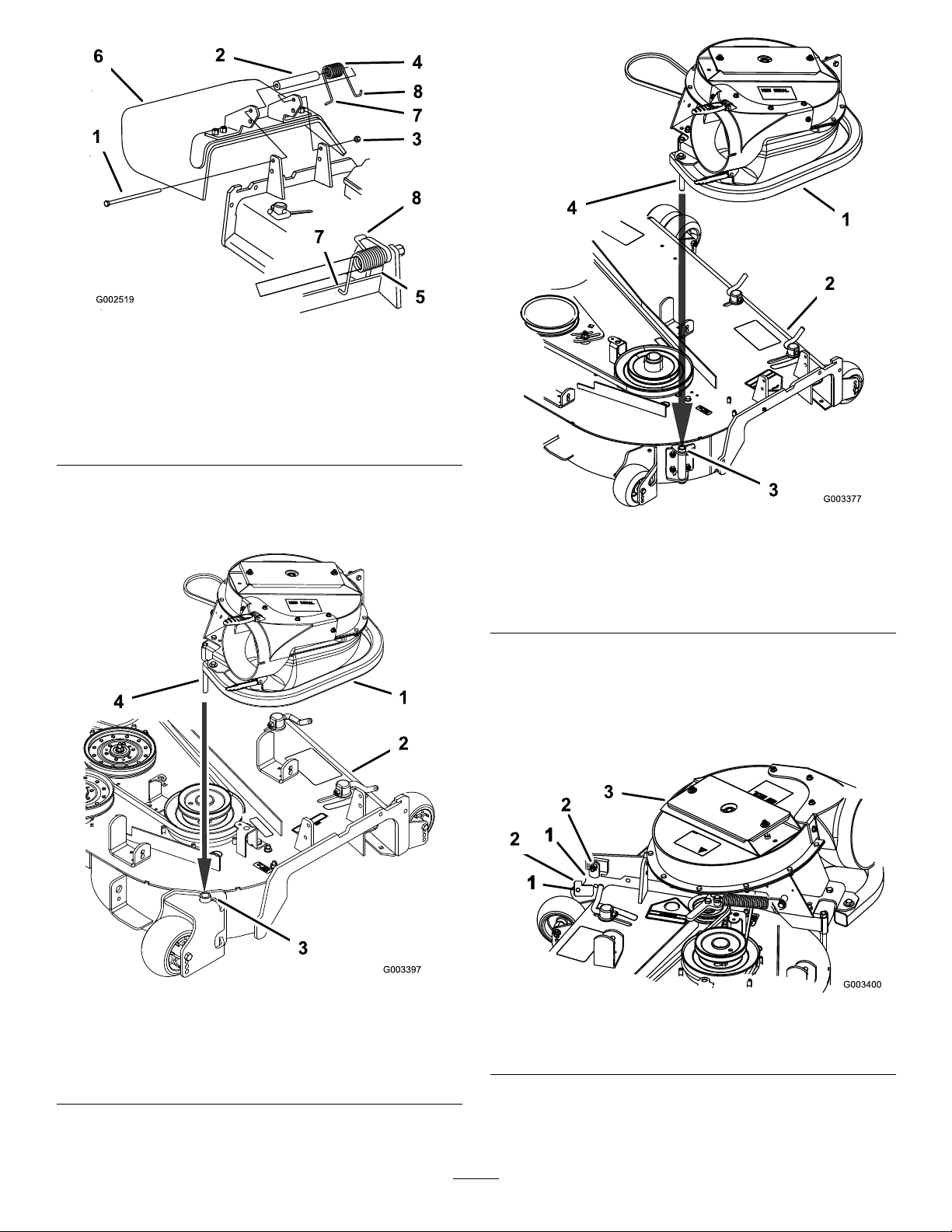
Figure12
1.Bolt
2.Spacer6.GrassDeector
3.Locknut
4.Spring8.Jhookendofspring
5.Springinstalled
7.Lendofspring,place
behinddeckedgebefore
installingbolt
2.Slidetheblowerassemblypegintothepivothole.
For60inchmowersrefertoFigure13andfor72
inchmowersrefertoFigure14.
Figure14
72inchMowerDeck
1.Blowerassembly3.Pivothole
2.Mowerdeck,72inch(183
cm)shown
4.Blowerassemblypeg
3.Closetheblowerassemblytoseeifthelatchesare
adjustedcorrectly.Loosenortightentheboltso
thelatchesrmlyholdtheblowerassemblyagainst
themowerdeck,butcanbereleasedbyhand
(Figure15).
Figure13
60inchMowerDeck
1.Blowerassembly3.Pivothole
2.Mowerdeck,60inch(152
cm)shown
4.Blowerassemblypeg
Figure15
1.Latch3.Blowerassembly
2.Bolt
4.InstallthespringasshowninFigure16.
Makesurethehooksareinthecorrectposition.
11
Page 12

8
SizingtheUpperTubefor60
inchMowerswithGasEngines
Partsneededforthisprocedure:
1Uppertube
Procedure
Figure16
1.Springloadedidlerpulley
2.Shorthookend
5.Pullthespringloadedidlerpulleybackandroute
thebeltaroundthemowerdeckpulley .Ensurethe
beltisroutedaroundtheblowerpulleyscorrectly
(Figure17).
3.Longhookend
Note:Thisprocedureisfor60inchmowerswithgas
enginesonly .
1.Measureup3–1/2inches(89mm)fromthebottom
oftheuppertube.Usetheexisting3holesasmarks
andthenmarkitinseveralplacestocreatealine
aroundthetube(Figure18).
2.Cutthe3–1/2inches(89mm)offtheuppertube
(Figure18).
Note:Noticethethreeindentationsinthetube.
Thisiswhereholeswillbedrilledinthefollowing
procedure.
Figure17
1.Mowerdeckpulley3.Blower
2.SpringloadedIdlerpulley
12
Page 13

Figure18
1.Indentationsfordrilling
holes
2.Uppertube5.Linetocuttube
3.Cutoff3–1/2inches(89
mm)for60inchmowers
withgasenginesonly
4.Usetheexistingholesto
createaline
2.Stoptheengine,removethekey,andwaitforall
movingpartstostopbeforeleavingtheoperating
position.
3.Lowerthemowerdecktothelowestheight-of-cut
position.
4.Installtheuppertubeintothebaggeropeningand
pullitbackoutsotherubbersealisprotrudingout
(Figure19).
Figure19
1.Uppertube3.Baggerhood
2.Baggeropening
5.Measurethedistancethetubeisinsidethehood.
Measurefromthehoodplatetotheedgeofthetube
asshowninFigure20.Thisdistanceneedstobe
3/4inch(19mm).
9
InstallingtheDischargeTubes
Partsneededforthisprocedure:
1Uppertube
1Lowertube
3
Bolt,(#10x3/4inches)
3
Locknut,(#10)
3
Washer,(7/32inch)
Procedure
Important:Makesurethemowerdeckisinthe
lowestheight-of-cutpositionwhileinstallingthe
dischargetubes.
Note:Remembertoreplacethegrassdeectorwhen
thebaggerisremovedfromthemower.Referto
ReplacingtheGrassDeector.
1.DisengagethePTOandsettheparkingbrake.
1.Hoodplate
2.Uppertube
3.Hoodinthedownposition
Figure20
4.3/4inch(19mm)
5.Edgeoftube
13
Page 14

6.Oncethe3/4inch(19mm)measurementhasbeen
achieved,marktheuppertubeontheoutsidewhere
therubbersealprotrudesout.Thisismarkedto
ensurethecorrectpositionfortheuppertubewhen
drillingtheholesandconnectingtheupperand
lowertubes(Figure21).
Note:Therubbersealmustprotrudeoutfromthe
baggerhood.
Figure22
1.Lowertube2.Uppertube
8.Slidethelowertubeontothebootandlatchthem
together(Figure23).
Figure21
1.Uppertube3.Baggerhood
2.Rubbersealprotrudingout4.Markhereagainstthe
rubberseal
7.Installthelowertubeintotheuppertube(Figure22).
Note:Thereisalatchonthetopandbottomof
theblowerhousing.
1.Blowerassembly3.Latch
2.Lowertube
14
Figure23
Page 15

9.Makesurethemowerdeckisinthelowest
height-of-cutpositionandthemarkontheupper
tubeisstillpositionedagainsttheprotrudingrubber
seal.
ChecktomakesurethemarkfromFigure21isstill
inplace.
10.Usingthethreeholesorindentationsintheupper
tubeasatemplate,drillthreeholes(7/32inch
diameter)wheretheupperandlowertubesjoin
together(Figure24).
1.Lowertube
2.Uppertube
3.Flatwasher,(7/32inch)
Figure25
4.Locknut,(#10)
5.Bolt,(#10x3/4inches)
Figure24
1.Baggerhood4.Lowertube
2.Uppertube5.Blowerassembly
3.Drill7/32inchdiameter
holeshere(useupper
tubeasatemplate)
11.Removethelowertubefromtheblower.
12.Jointheupperandlowertubeswith3bolts(#10
x3/4inches),3atwashers(7/32inch),and3
locknuts(#10)(Figure25).
13.Installthelowertubeontotheblowerhousingand
secureitwiththelatches.
10
InstallingtheBeltCover
Partsneededforthisprocedure:
Beltcover(fromBlowerandDriveKit)
Procedure
1.Lowerthemowerdecktothelowestheight-of-cut
position.
2.Installthenewbeltcoversothenotchesonboth
sidesgooverthebeltcoversupportsandsecurethe
latch(Figure26).
15
Page 16
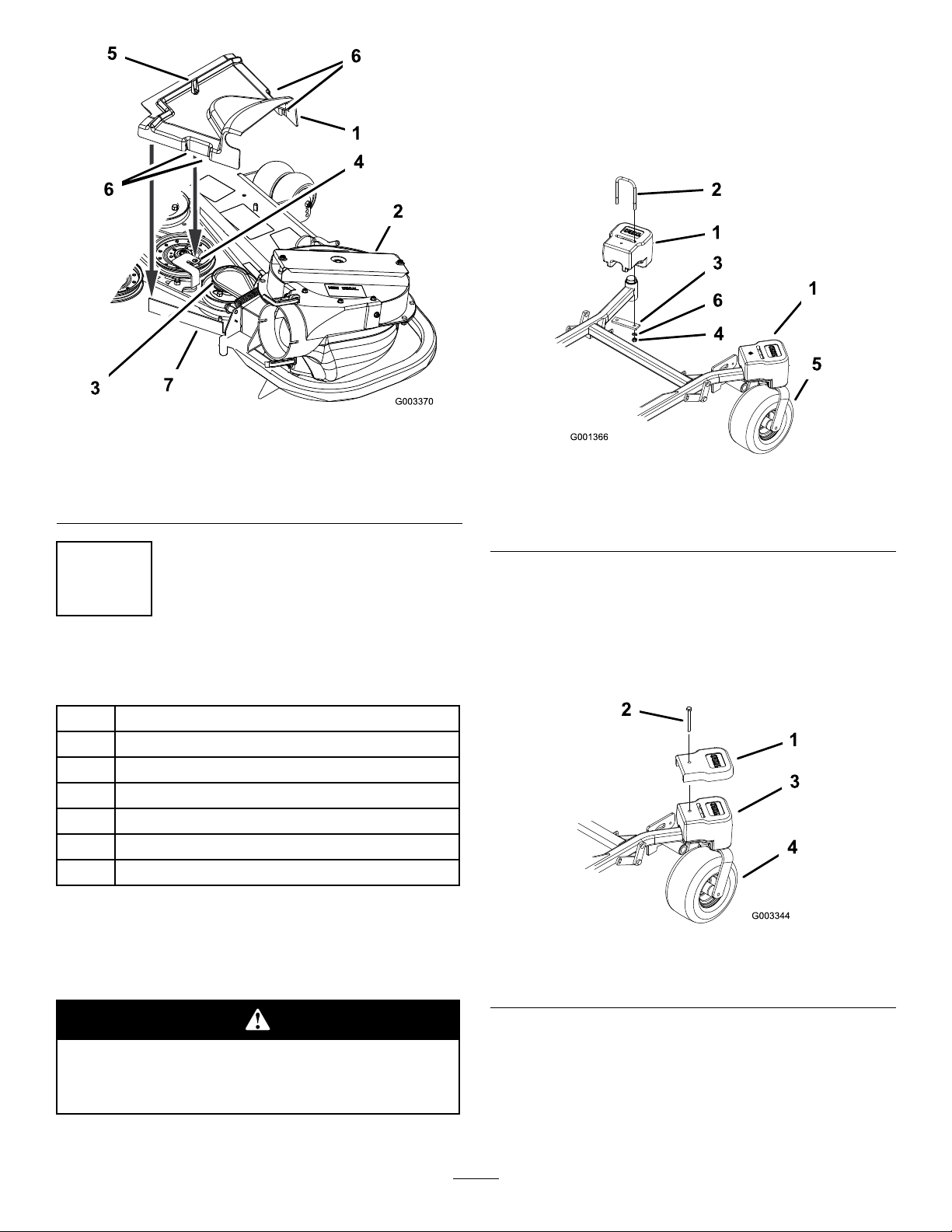
Figure26
1.Beltcover5.Latch
2.Blowerassembly6.Beltcovernotch
3.Pulleyassembly7.Beltcoversupport
4.Beltcoverbracket
2.Installplate,nuts(1/2inch)andlockwasher
(1/2inch)undertheframeandweight(Figure27).
3.Repeatforoppositeside.
Note:AllZMastermowersreceivethecaster
weights.
Figure27
1.Frontcasterweight4.Nut
2.U-bolt5.Frontcaster
3.Plate6.Lockwasher
11
InstallingtheWeights
Partsneededforthisprocedure:
2
Casterweight
2U-bolt
4
Nut,(1/2inch)
4
Lockwasher,(1/2inch)
2Plate
2
Topweight(for60inchmowerdecksonly)
2
Procedure
TocomplywithANSI/OPEIB71.4-2004Standard,
weightsmustbeaddedtothemachine.
Note:OnlyZMastermowerswith60inchmower
decksreceivethetopweights.
4.Installthetopweightsontopofeachcasterweight
for60inchmowerswith2bolts(1/2x2–1/2inches)
(Figure28).
Figure28
1.Topweight3.Frontcasterweight
2.Bolt,(1/2x2–1/2inches)
4.Frontcasterwheel
Thebaggeraddsalotofweighttotherear
ofthemachineandmaycauseanunstable
conditionwhichcouldresultinalossofcontrol.
1.Placecasterweightsonthefrontcasters.
16
Page 17
12
13
AdjustingtheParkingBrake
NoPartsRequired
Procedure
Checktheparkingbrakeforproperadjustment.
1.Disengagebrakelever(leverdown).
2.Measurethelengthofthespring.
Themeasurementshouldbe2-3/4inch(70mm)
betweenwashers(Figure29).
CheckingtheTirePressure
NoPartsRequired
Procedure
Note:Increasethetirepressureduetotheadditional
weight.
Checkandincreasetheairpressureinthefrontcaster
wheelsandreartires(Figure30).
Pressure:Reartires-20psi(138kPa)
Frontcasterwheels-25psi(172kPa)
Figure29
1.Brakelever
2.Spring(2-3/4inches/70
mm)
3.Adjustingnuts7.Trunnionroller
4.Collaronbrakerod
3.Ifadjustmentisnecessary,loosenthejamnutbelow
thespringandtightenthenutdirectlybelowthe
yoke(Figure29).Turnthenutuntilthecorrect
measurementisobtained.Tightenthetwonuts
togetherandrepeatonoppositesideofunit.
4.Turnnutsclockwisetoshortenspringlengthand
turncounter-clockwisetolengthenthespring.
5.Engageparkingbrake,leverup.
6.Measurethedistancebetweenthetrunnionroller
andthecollaronbrakerod.
Themeasurementshouldbe3/16-1/4inch(5-7
mm)(Figure29).
7.Ifadjustmentisnecessary,loosenthejamnut
directlybelowtheyoke.Turnthebottomroduntil
thecorrectmeasurementisobtained(Figure29).
Tightenjamnutatyoke
5.3/16–1/4inch(5–7mm)
6.Jamnutandyoke
Figure30
17
Page 18
Operation
Note:Determinetheleftandrightsidesofthe
machinefromthenormaloperatingposition.
Important:Settheparkingbrakewhenleavingthe
machineunattended,evenifjustforafewminutes.
Toavoidpersonalinjury,followthese
procedures:
•Becomefamiliarwithalloperatingand
safetyinstructionsintheoperator’smanual
foryourmowerbeforeusingthisattachment.
•Neverremovethebaggerorbaggertubes
whiletheengineisrunning.
•Alwaysshuttheengineoffandwaitforall
movingpartstostopbeforeclearingan
obstructionfromthebaggingsystem.
•Neverdomaintenanceorrepairswhilethe
engineisrunning.
Childrenorbystandersmaybeinjuredifthey
moveorattempttooperatethetractorwhileit
isunattended.
Alwaysremovetheignitionkeyandsetthe
parkingbrakewhenleavingthemachine
unattended,evenifjustforafewminutes.
PositioningtheAdjustable
Bafe
AdjustthebafetopositionB(middleposition)for
bagging.RefertothemachinesOperatorManualfor
thebafeadjustmentprocedure.
•Settheparkingbrake.
Withoutthegrassdeector,baggertubesor
completecollectionsystemmountedinplace,
youandothersareexposedtobladecontact
andthrowndebris.Contactwiththerotating
mowerblade(s)andthrowndebriswillcause
injuryordeath.
•Alwaysinstallthegrassdeectorwhen
removingthecollectionsystemand
changingtosidedischargemode.
•Ifthegrassdeectoriseverdamaged,
replaceitimmediately.Thegrassdeector
routesmaterialdowntowardtheturf.
•Neverputyourhandsorfeetunderthe
mower.
•Nevertrytoclearthedischargeareaor
mowerbladesunlessyoumovethepower
takeoff(PTO)tooffandrotatetheignition
keytooff.Alsoremovethekeyandpullthe
wireoffofthesparkplug(s).
Figure31
•Turnofftheenginebeforeuncloggingthe
dischargechute.
18
Page 19

EmptyingtheBagger
1.DisengagethePTOandsettheparkingbrake.
2.Liftuponthehandletoopenthedoorandempty
thehopper.
3.Pushthehandledowntoclosethedoor(Figure32).
Note:Ifthemachineistobedrivenontoatruck
ortrailerwiththehopperfull,alwaysbackupthe
ramp.Thiswillreducethechanceofrearwardtip.
Figure32
Note:Inmostcases,thedebriscanbeshakenout
ofthetubes.
7.Iftheblowerassemblyisplugged,unlatchthe
blowerassembly,removethebelt,andswingitopen.
8.Usingastickorsimilarobject,notyourhands,to
removeandcleartheobstructionfromtheblower
assembly.
9.Afteryouremovetheobstruction,installthe
completecollectionsystemandresumeoperation.
RemovingtheBagger
Componentsaroundenginewillbehotifthe
machinehasbeenrunning.Touchinghot
componentscancauseburns.
•Donottouchenginecomponentswhenhot.
ClearingObstructionsfrom
theCollectionSystem
Whenthecollectionsystemisinoperation,the
blowercanberotatingandcutofforinjure
hands.
•Beforeadjusting,cleaning,repairing
andinspectingtheblower,andbefore
uncloggingthechute,turnofftheengine
andwaitforallmovingpartstostop.
Removethekey .
•Useastick,notyourhands,toremovean
obstructionfromtheblowerandtube.
•Keepface,hands,feet,andanyotherpartof
yourbodyorclothingawayfromconcealed,
moving,orrotatingparts.
1.DisengagethePTOandsettheparkingbrake.
2.Turnofftheengine,removethekey,andwaitforall
movingpartstostopbeforeleavingtheoperating
position.
3.Emptythebagger.
4.Unlatchthelowertube.
5.Removethetubesfromthebagger.
6.Usingastickorsimilarobject,notyourhands,to
removeandcleartheobstructionfromthetube
assembly.
•Allowenginetocoolbeforeremovingthe
bagger.
1.DisengagethePTO ,settheparkingbrake,and
chockorblockthetires.
2.Turnofftheengine,removethekey,andwaitforall
movingpartstostopbeforeleavingtheoperating
position.
3.Unlatchthelowertubefromtheblowerandremove
thetubefromtheblowerassembly.
4.Removethetubefromthebaggerhood.
5.Lowerthemowerdecktothelowestheight-of-cut
position.
6.Unlatchthebeltcoveroverthemowerpulley
assembly.
7.Removetheblowerbeltfromthemowerpulley
assembly.
8.Opentheblowerassembly .
9.Removetheblowerassemblyfromthepivothole.
10.Ifyouarechangingtosidedischargemode,ensure
thegrassdeectorisinstalledandcanbelowered
intoworkingposition.
11.Removethecollectionsystemassembly.
19
Page 20

UsingtheGrassDeector
Withoutthegrassdeector,dischargecover,
orcompletegrasscatcherassemblymounted
inplace,youandothersareexposedtoblade
contactandthrowndebris.Contactwith
rotatingmowerblade(s)andthrowndebriswill
causeinjuryordeath.
•Alwaysinstallthegrassdeectorwhen
removingthecollectionsystemand
changingtosidedischargemode.
•Ifthegrassdeectoriseverdamaged,
replaceitimmediately.Thegrassdeector
routesmaterialdowntowardtheturf.
•Neverputyourhandsorfeetunderthe
mower.
CuttingHeight
Foroptimumbaggingperformance,setthedeck
height-of-cuttoremovenomorethat2to3inches(51
to76mm)or1/3ofthegrassheight,whicheverisless.
Cuttingoffmorethanthiswillreducethecapacityof
thevacuumsystem.
CuttingFrequency
Cutthegrassoften,especiallywhenitgrowsrapidly.
Youwillhavetocutyourgrasstwiceifitgetsexcessively
long(refertoBaggingLongGrass).
CuttingTechnique
Forbestlawnappearance,besuretoslightlyoverlap
themowerintothepreviouslycutarea.Thishelps
reducetheloadontheengineandreducesthechance
ofpluggingtheblowerassemblyandtubes.
•Nevertrytoclearthedischargeareaor
mowerbladesunlessyoumovethepower
takeoff(PTO)totheoffposition,rotatethe
ignitionkeytooffandremovethekey .
TransportingMachines
Donotleavegrassordebrisinthebaggerwhile
transportingthemachineonatrailerortruck.
Transportingthemachinewithgrassordebris
inthebaggercandamagethemachine.
Donotleavegrassordebrisinthebaggerwhile
transportingthemachineonatrailerortruck.
OperatingTips
BaggingSpeed
Thebaggingsystemmayplugifyoudrivetoofastand
theenginespeedgetstooslow .Onhillsitmaybe
necessarytoslowthemachinesgroundspeed.Mow
downhillwheneverpossible.
Asthebaggerlls,extraweightisaddedto
thebackofthemachine.Ifyoustopandstart
suddenlyonhills,youmaylosesteeringcontrol
orthemachinemaytip.
•Donotstartorstopsuddenlywhengoing
uphillordownhill.Avoiduphillstarts.
•Ifyoudostopthemachinewhengoing
uphill,disengagethePTO.Thenbackdown
thehillusingaslowspeed.
•Donotchangespeedsorstoponslopes.
MachineSize
Rememberthatthemachineislongerandwiderwith
thisattachmentinstalled.Byturningtoosharplyin
connedplacesyoumaydamagetheattachmentor
otherproperty.
Trimming
Alwaystrimwiththeleftsideofthemower.Donot
trimwiththerightsideofthemowerbecauseyoucould
damagethebaggingtubes.
BaggingLongGrass
Ifthegrassiseverallowedtogrowlongerthannormal,
orifitcontainsahighdegreeofmoisture,raisethe
cuttingheighthigherthanusualandcutandbagthe
grassatthissetting.Thencutandbagthegrassagain
usingthelower,normalsetting.
Excessivelylonggrassisheavyandmaynotbe
propelledcompletelyintothebagger.Ifthishappens,
thetubeandblowermayplug.Toavoidpluggingthe
baggingsystem,mowthegrassatahighheight-of-cut,
20
Page 21

thenlowerthemowertoyournormalcuttingheight
andrepeatthebaggingprocess.
BaggingWetGrass
Ifpossible,alwaystrytocutgrasswhenitisdry.Wet
grasscancauseplugging.
ReducingPlugging
Toavoidpluggingthebaggingsystem,reduceground
speedandmowthegrassatahighheight-of-cut,then
lowerthemowertoyournormalcuttingheightand
repeatthebaggingprocess.
SignsofPlugging
Asyouarebagging,asmallamountofgrassclippings
normallyblowoutthefrontofthemower.Anexcessive
amountofclippingblow-outindicatesthatthebagger
isfullorthetubeisplugged.
BaggingBlades
Inmostmowingconditions,thestandardhighlift
bladeswillprovidethebestbaggingperformance.
TheT oroAtomicbladeisrecommendedforbagging
leavesindryconditions.Indrydustyconditions,the
mediumliftorlowliftbladeswillreducedustanddirt
blowoutwhileprovidingeffectivebaggingairow .
ContactanAuthorizedServiceDealerfortheproper
bladesfordifferentmowingconditions.
CurbClimbingandLoading
Alwaysliftthedecktothehighestpositionwhenloading
themachineontrailersorascending/descendinga
curb.Leavingthemowerinalowerpositioncancause
damagetothemowerwhileloadingandgoingovera
curb.Ifacurbishigherthan6inches(152mm),crossit
atasharpanglewiththedeckfullyraised.Useextreme
cautionwhenloadingontoatrailer.
21
Page 22

Maintenance
RecommendedMaintenanceSchedule(s)
MaintenanceService
Interval
Aftertherst8hours
Beforeeachuseordaily
Every25hours
Every50hours
Every100hours
MaintenanceProcedure
•Inspecttheblowerbelt.
•Inspectthecollectionsystem.
•Cleanthehoodscreen.
•Cleanthecollectionsystem.
•Inspecttheblowerbelt.
•Greasetheidlerarm.
•Greasethehandlepivot.
•Inspectthecollectionsystem.
CleaningtheBaggerScreen
ServiceInterval:Beforeeachuseordaily
Thescreensneedtobecleanedbeforeeachuse.Inwet
grasstheywillneedtobecleanedmoreoften.
1.Disengagethepowertakeoff(PTO)andsetthe
parkingbrake.
2.Turnofftheengine,removethekey,andwaitforall
movingpartstostopbeforeleavingtheoperating
position.
3.Openthebagger.
4.Cleanthedebrisfromthescreen.
5.Closethebagger.
ReplacingtheBlowerBelt
1.DisengagethePTO,movethemotioncontrollevers
totheneutrallockedposition,andsettheparking
brake.
2.Stoptheengine,removethekey,andwaitforall
movingpartstostopbeforeleavingtheoperating
position.
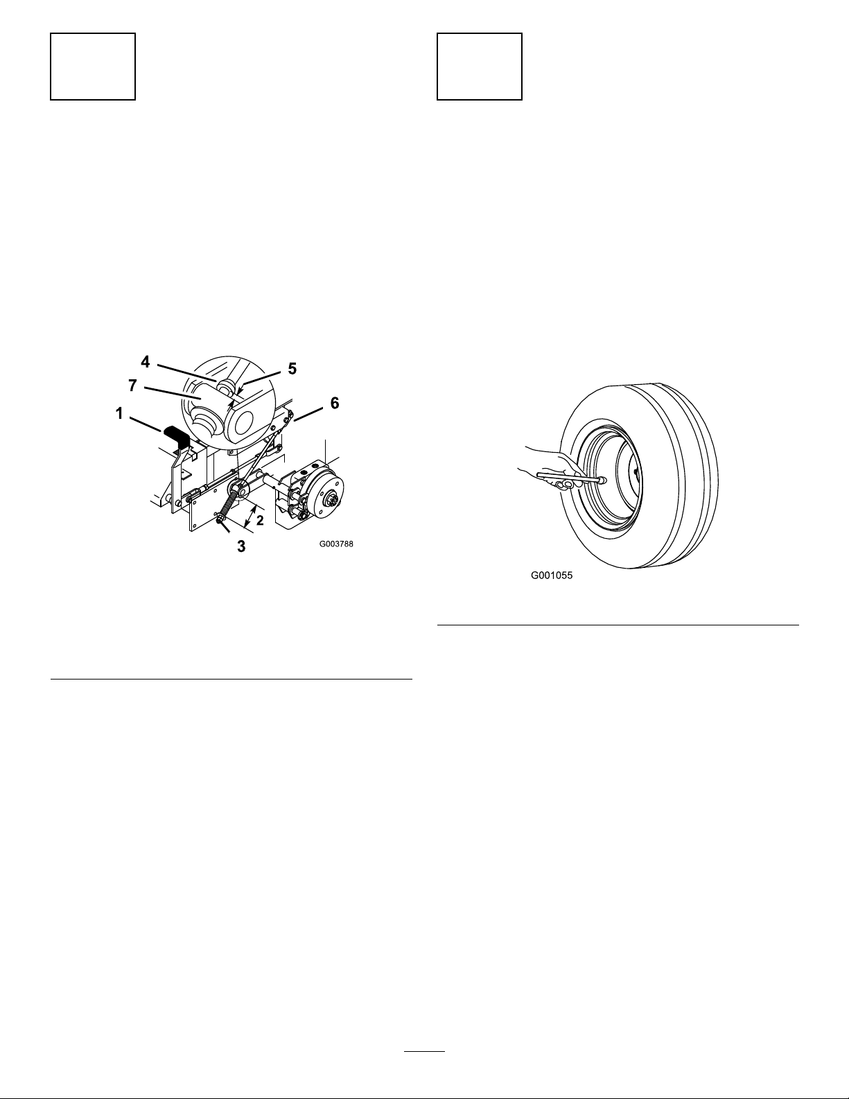
3.Pullbackonthespringloadedidlerpulleytorelieve
thebelttension(Figure33).
4.Removetheexistingblowerbeltfromthemower
deckpulleyandthentheblowerpulleys.
5.Installthenewbeltaroundtheblowerpulleysand
themowerdeckpulley(Figure33).
CleaningtheCollection
System
ServiceInterval:Beforeeachuseordaily
1.Washtheinsideandoutsideofthebaggerhood,
tube,andtheundersideofthemower.Useamild
automotivedetergenttoremovedirt.
2.Makesureyouremovemattedgrassfromallparts.
3.Afterwashingallparts,letthemdrythoroughly.
Note:Withallpartsinstalled,startandrunthemachine
foraminutetoassistindrying.
InspectingtheBlowerBelt
ServiceInterval:Aftertherst8hours
Every25hours
Checkbeltsforcracks,frayededges,burnmarksorany
otherdamage.Replacedamagedbelts.
22
Page 23

Figure33
1.Idlerpulley4.Peg
2.Mowerdeckpulley5.Belt
3.Spring
Figure35
1.Latch3.Blowerassembly
2.Bolt
6.Blowerpulley
GreasingtheIdlerArmand
6.InstallthespringasshowninFigure34.
Figure34
1.Springloadedidlerpulley
2.Shorthookend
3.Longhookend
7.Pullbackonthespringloadedidlerpulleyand
installthebeltontothespringloadedidlerpulley
(Figure33).
HandlePivot
ServiceInterval:Every50hours—Greasetheidler
arm.
Every100hours—Greasethehandle
pivot.
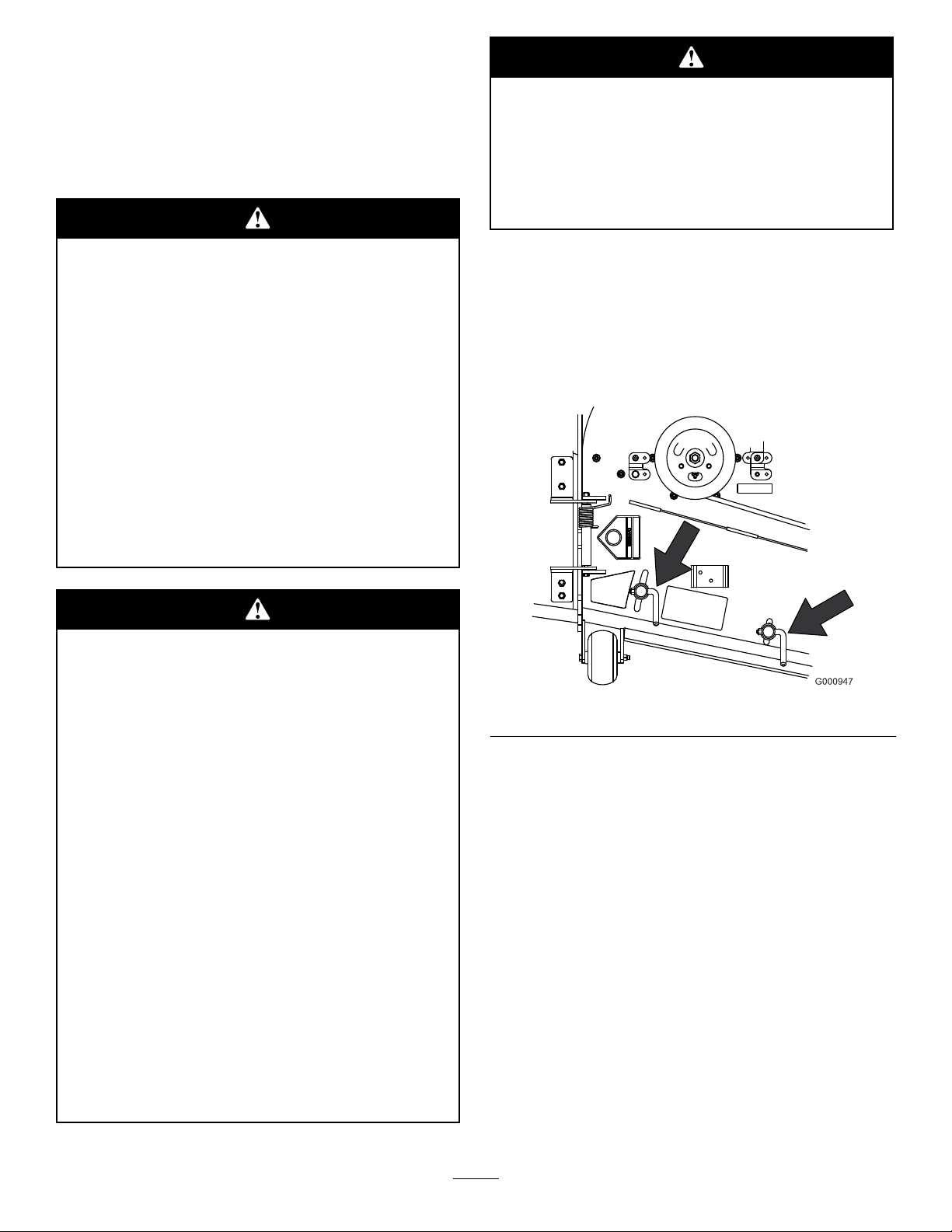
Greasetheblowerbeltidlerarm(Figure36).
Figure36
CheckingandAdjustingthe
BlowerLatch
Closetheblowerassemblytoseeifthelatchesare
adjustedcorrectly.Loosenortightentheboltssothe
latchesrmlyholdtheblowerassemblyagainstthe
mowerdeck,butcanbereleasedbyhand.
23
Page 24

Greasethehandlepivot(Figure37).
Figure37
InspectingtheCollection
System
ServiceInterval:Aftertherst8hours
Every100hours
1.DisengagethePTO,movethemotioncontrollevers
totheneutrallockedposition,andsettheparking
brake.
2.Stoptheengine,removethekey,andwaitforall
movingpartstostopbeforeleavingtheoperating
position.
3.Checktheuppertube,lowertube,bagger,andthe
blowerassembly.Replacethesepartsiftheyare
crackedorbroken.
4.Checkthebaggerframe.Replaceanypartsthatare
crackedorbroken.
5.Tightenallnutsboltsandscrews.
5.Afterthestopboltshavebeenadjusted,thelengthof
thehingelinkscanbeadjustedtoprovidecomplete
closingofthedoorandreasonableforceonthe
handle.Lengthenthelinkstoreducetheforce.
Shortenthelinkstoincreasetheforce(Figure38
andFigure39).
6.Makesureboththeleftandrightsidesareadjusted
thesamedistance.Withthedoorclosed,thelinks
shouldbeslightlytighttominimizerattling.
7.Tightenthenuts.
Figure38
1.Contactarmstraightup
anddown
2.Stopbolt
3.Hingelinks
AdjustingtheDoorClosing
Thetwohingelinksandtwostopscrewscanbeadjusted
toprovidecompleteclosingofthedoor.
1.DisengagethePTO,movethemotioncontrollevers
totheneutrallockedposition,andsettheparking
brake.
2.Stoptheengine,removethekey,andwaitforall
movingpartstostopbeforeleavingtheoperating
position.
3.Withthedoorclosed,thestopboltsneedtobe
adjustedsothatthecontactarmisstraightupand
down(Figure38andFigure39).
4.Ifadjustmentisneed,loosenthenutsandadjustthe
stopbolts(Figure38andFigure39).
24
1.Contactarm
2.Stopbolt
Figure39
3.Hingelinks
Page 25

AdjustingtheDoorOpening
Performthisafteradjustingthedoorclosing.
Adjustthehandlelinktoobtainthemaximumdoor
opening.Lengthenthehandlelinktoopenthedoor
farther.Shortenthehandlelinktoopenthedoorless
(Figure40).
Note:Themaximumdooropeningiscontrolledbythe
contactarmhittingthestop.Thestopisnotadjustable
andpreventsthedoorfrombeingopenedtoofar.
Figure40
1.Handle
2.Handlelink
3.Stop
Figure41
1.Latchlink2.Latchrod
InspectingtheMowerBlades
1.Inspectthemowerbladesregularlyandwhenevera
bladestrikesaforeignobject.
2.Ifbladesarebadlywornordamaged,installnew
blades.RefertoyourmowerOperator’ sManualfor
completeblademaintenance.
InstallingtheMowerBlades
AdjustingtheLatches
Thelatchescanbeadjustaftertheopenandcloseddoor
positionshavebeenset.
1.DisengagethePTO,movethemotioncontrollevers
totheneutrallockedposition,andsettheparking
brake.
2.Stoptheengine,removethekey,andwaitforall
movingpartstostopbeforeleavingtheoperating
position.
3.Closethedoor.
4.Checkthetoensurethelatchescompletelyengage
andcontactsthelatchrodweldedtothedoor
(Figure41).
5.Thelatchesneedtobetightagainstthelatchrod.
Theyneedtobelooseenoughtomoveorwiggle.
Inmostmowingconditions,thestandardhighliftblades
willprovidethebestbaggingperformance.
TheToroAtomicbladeisrecommendedforbagging
leavesindryconditions.Indrydustyconditions,the
mediumliftorlowliftbladeswillreducedustanddirt
blowoutwhileprovidingeffectivebaggingairow .
ContactanAuthorizedServiceDealerfortheproper
bladesfordifferentmowingconditions.
RefertothemowerOperator’ sManualformore
informationoninstallingblades.
25
Page 26

InstallingtheGrassDeector
Storage
1.Cleanthebagger.RefertoCleaningtheBagger.
Anuncovereddischargeopeningcouldallow
thelawnmowertothrowobjectsinthe
operator’sorbystander’sdirectionandresult
inseriousinjury.Also,contactwiththeblade
couldoccur.
•Neveroperatethelawnmowerunlessyou
installacoverplate,amulchplate,oragrass
chuteandcatcher.
•Makesurethegrassdeectorisinthedown
position.
1.Removethelocknut,bolt,springandspacerholding
thedeectortothepivotbrackets(Figure42).
2.Removethedamagedorworngrassdeector.
3.Placethespacerandspringontothegrassdeector.
PlacetheLendofthespringbehindthedeckedge.
Note:MakesuretheLendofthespringisinstalled
behindthedeckedgebeforeinstallingtheboltas
showninFigure42
4.Installtheboltandnut.
5.PlacetheJhookendofthespringaroundthegrass
deector(Figure42).
2.Inspectthebaggerfordamage.RefertoInspecting
theCollectionSystem.
3.Makesurethebaggerisemptyandthoroughlydry.
4.Checkthebeltforwearorcracks.
5.Storethemachineinaclean,dryplace,outofdirect
sunlight.Ifyoumuststorethemachineoutside,
coveritwithaweatherproofcover.Thisprotectsthe
plasticpartsandextendsthelifeofthemachine.
Important:Thegrassdeectormustbeableto
lowerdownintoposition.Liftthedeectorup
totestthatitlowersintothefulldownposition.
Figure42
1.Bolt
2.Spacer6.GrassDeector
3.Locknut
4.Spring8.Jhookendofspring
5.Springinstalled
7.Lendofspring,place
behinddeckedgebefore
installingbolt
26
Page 27

Troubleshooting
Problem
Abnormalvibration.
Reducedbaggingperformance.
Blowerandtubesplugtoofrequently.
PossibleCauseCorrectiveAction
1.Cuttingblade(s)is/arebentor
unbalanced.
2.Blademountingboltisloose.2.Tightentheblademountingbolt.
3.Looseblowerpulleyorpulleyassembly.3.Tightentheappropriatepulley.
4.Wornblowerbelt.4.Replacebelt.
5.Blowerfanblade(s)is/arebentor
unbalanced.
1.Lowenginespeed.1.Alwaysoperatethecollectionsystem
2.Pluggedscreeninbaggerhood.2.Removedebris,leavesorgrass
3.Looseblowerbelt.3.Replacetheblowerbelt.
4.Apluggedtubeorblower.4.Locateandremovepluggeddebris.
5.Fullbagger .5.Emptythebagger.
1.Baggeristoofull.1.Dumpmorefrequently.
2.Lowenginespeed.2.Alwaysoperatethecollectionsystem
3.Grassistoowet.3.Cutgrasswhenitisdry.
4.Grassistoolong.4.Cutnomorethan2-3inches(51-76
5.Pluggedscreeninhood.5.Removedebris,leavesorgrass
6.Groundspeedistoofast.6.Drivesloweratfullthrottle.
7.Wornblowerbelt.7.Replacebelt.
1.Installnewcuttingblade(s).
5.ContactanAuthorizedServiceDealer.
atfullthrottle.
clippingsfromthescreen.
atfullthrottle.
mm)or1/3ofthegrassheight,which
everisless.
clippingsfromthescreen.
Debrisblowout.
Blowerimpellerdoesnotspinfreely .
1.Baggeristoofull.1.Dumpmorefrequently.
2.Groundspeedistoofast.2.Drivesloweratfullthrottle.
3.Mowerdeckisnotleveled.
1.Pluggedblower .1.Removedebris,leavesorgrass
2.Impellernotaligned.
3.Seethemoweroperator’smanualfor
levelingthemowerdeck.
clippingsfromtheblowerimpeller.
2.ContactanAuthorizedServiceDealer.
27
Page 28

Landscape
Contractor
Equipment (LCE)
The Toro Total Coverage Guarantee
A Limited Warranty
Conditions and Products Covered
The Toro® Company and its afliate, Toro Warranty Company, pursuant to an
agreement between them, jointly promise to repair the listed Toro Products if
defective in materials or workmanship. The following time periods apply from
the date of purchase:
This warranty applies to:
•
ProLine Mid-Size Mowers and Attachments
•
Z Master Mid-Mount ZRTs and Attachments
Components
Traction Unit Frame and Carrier Frame
All Spindles
Engines* and /Hydraulic System
Deck Shells (34 ″ -72 ″ )
Z500 Series Electric Clutch
Remaining Components
* S o m e e n g i n e s u s e d o n T o r o L C E P r o d u c t s a r e w a r r a n t e d b y t h e e n g i n e m a n u f a c t u r e r .
This warranty includes the cost of parts and labor, but you must pay
transportation costs.
Warranty Period
1 year
1 year
2 year
3 years Parts
2 years Labor
2 years
2 years
2 years
1 year
Instructions for Obtaining Warranty Service
If you think that your Toro Product contains a defect in materials or
workmanship, follow this procedure:
1. Contact any Toro Authorized or Master Service Dealer to arrange service at
their dealership. To locate a dealer convenient to you, access our website at
www.Toro.com. You may also call our Toro Customer Care Department
toll free at 888–865–5676 (U.S. Customers) or 888–865–5691 (Canada
customers).
2. Bring the product and your proof of purchase (sales receipt) to the Service
Dealer.
If for any reason you are dissatised with the Service Dealer’s analysis or with
the assistance provided, contact us at:
LCB Customer Service Department
Toro Warranty Company
8111 Lyndale Avenue South
Bloomington, MN 55420-1196
Owner Responsibilities
You must maintain your Toro Product by following the maintenance procedures
described in the operator’s manual. Such routine maintenance, whether
performed by a dealer or by you, is at your expense.
Items and Conditions Not Covered
There is no other express warranty except for special emission system coverage
on some products. This express warranty does not cover the following:
• Cost of regular maintenance service or parts, such as lters, fuel, lubricants,
tune-up parts, blade sharpening, brake and clutch adjustments.
• Any product or part which has been altered or misused or required
replacement or repair due to normal wear, accidents, or lack of proper
maintenance.
• Repairs necessary due to improper fuel, contaminants in the fuel system, or
failure to properly prepare the fuel system prior to any period of non-use
over three months.
• Pickup and delivery charges.
General Conditions
All repairs covered by this warranty must be performed by an Authorized Toro
Service Dealer using Toro approved replacement parts.
Neither The Toro® Company nor Toro Warranty Company is liable for
indirect, incidental or consequential damages in connection with the
use of the Toro Products covered by this warranty, including any
cost or expense of providing substitute equipment or service during
reasonable periods of malfunction or non-use pending completion
of repairs under this warranty.
Some states do not allow exclusions of incidental or consequential
damages, or limitations on how long an implied warranty lasts, so
the above exclusions and limitations may not apply to you.
All implied warranties of merchantability (that the product is t
for ordinary use) and tness for use (that the product is t for
a particular purpose) are limited to the duration of the express
warranty.
This warranty gives you specic legal rights, and you may also have
other rights which vary from state to state.
Countries Other than the United States or Canada
Customers who have purchased Toro products exported from the United States or Canada should contact their Toro Distributor (Dealer) to obtain guarantee
policies for your country, province, or state. If for any reason you are dissatised with your Distributor’s service or have difculty obtaining guarantee information,
contact the Toro importer. If all other remedies fail, you may contact us at Toro Warranty Company.
374-0037 Rev F
 Loading...