

Page 1

DeluxeSeatKit
ZMaster
ModelNo.117-6174
ModelNo.78540
®
G3RidingMower
Installation
LooseParts
Usethechartbelowtoverifythatallpartshavebeenshipped.
FormNo.3370-467RevA
InstallationInstructions
ProcedureDescription
1
2
3
4
5
6
1
Qty.
Nopartsrequired
Nopartsrequired
SeatBeltKit
Deluxesuspensionseat1
Flangenut(5/16inch)
Plasticties4
Deluxesuspensionseat1
Flangenut(5/16inch)
Flangenut(3/8inch)(International
mowersonly)
Plasticties4
Decal1Installthedecal.
–
–
1Installtheseatbelt.
4
4
4
Removetheseat(Domesticand
AustralianMowers).
Removetheseat(InternationalMowers).
Installtheseat(DomesticandAustralian
Mowers).
Installtheseat(InternationalMowers).
Use
RemovingtheSeat(Domestic
andAustralianMowers)
NoPartsRequired
Procedure
1.Unlatchtheseatandtiptheseatforward.
2.Removethenutsholdingtheseattothemounting
frame(Figure1).
3.Disconnectthewireharnessfromtheseatswitch.
4.Removetheseatfromtheframeandsetitaside.
©2011—TheToro®Company
8111LyndaleAvenueSouth
Bloomington,MN55420
Registeratwww.T oro.com.
1.Seat
2.Seatframe
Figure1
3.Nut
OriginalInstructions(EN)
PrintedintheUSA.
AllRightsReserved
Page 2
2
RemovingtheSeat
(InternationalMowers)
NoPartsRequired
Procedure
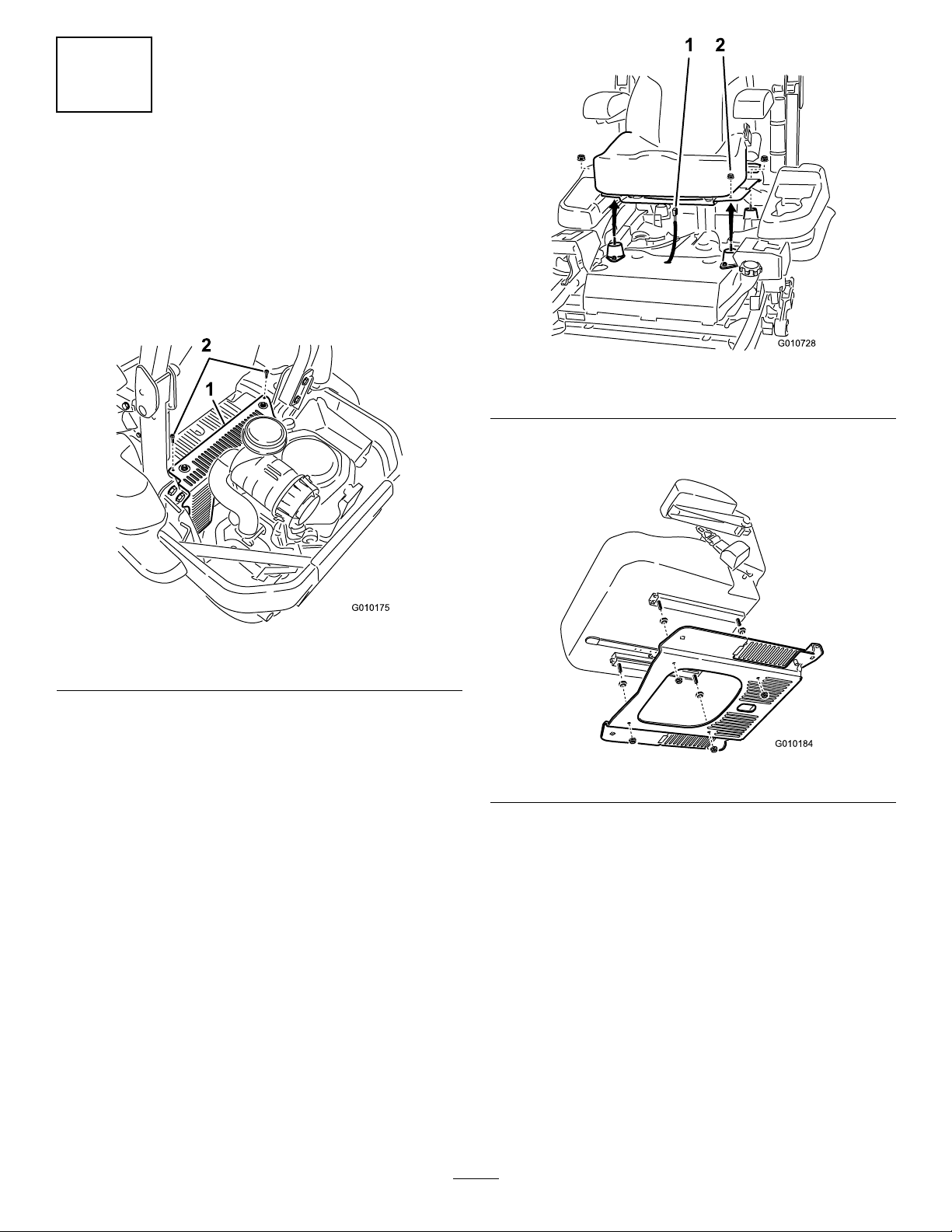
1.Removethehydraulicunitshroudfromthemachine
Figure2).Savehardwareandshroud.
(
Figure3
1.Harnessconnector2.Flangenuts
4.Removetheseatplatefromtheseatbyremovingthe
4spacersand4angenuts(Figure4).
Figure2
1.Hydraulicunitshroud2.Bolts
2.Removethe4angenutsholdingtheseattothe
machine(Figure3).
3.Unplugtheharnessconnectorfromtheseatswitch
locatedundertheseattowardsthefront(Figure3).
Figure4
2
Page 3
3
InstallingtheSeatBelt
Partsneededforthisprocedure:
1
SeatBeltKit
Procedure
WARNING
Seriousinjuryordeathcanhappenwhentheseat
beltisusedwithoutarollbarinstalled.
Donotinstalltheseatbeltwithoutarollbar
installed.
Ifyoudonothavearollbar,contactanAuthorized
ServicedealertoobtainthecorrectRollOver
ProtectionSystem(ROPS).
WARNING
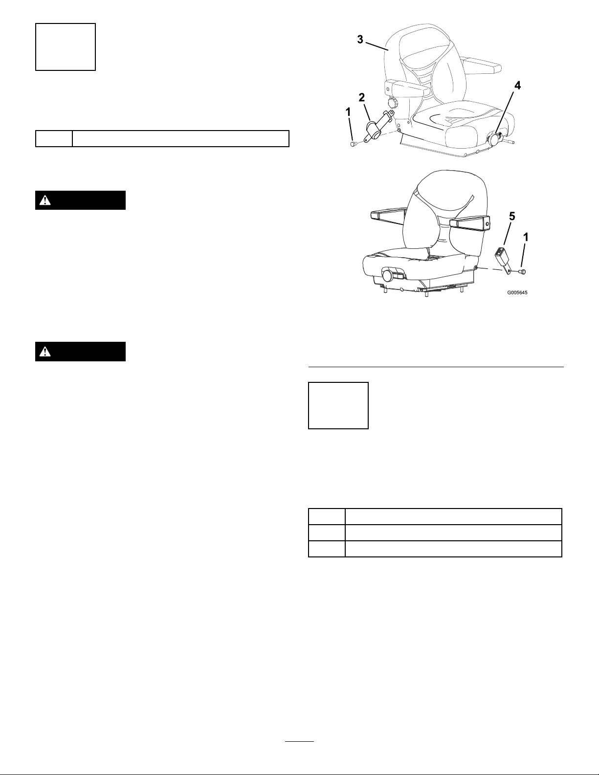
Figure5
1.Bolt,(7/16x1inch)4.Suspensionadjustment
knob
2.Seatbeltretractor5.Seatbeltreceiver
3.Seat
Toavoidinjuryordeathfromrollover:keepthe
rollbarintheraisedlockedpositionandusethe
seatbelt.
Ensurethattherearpartoftheseatissecuredwith
theseatlatch.
Installtheseatbeltkitretractorandreceivertothe
deluxeseatusingthe2bolts(7/16x1inch)(Figure5).
Torquetheboltsto55ft.-lb.(74.6N-m).
4
InstallingtheSeat(Domestic
andAustralianMowers)
Partsneededforthisprocedure:
1Deluxesuspensionseat
4
Flangenut(5/16inch)
4Plasticties
Procedure
1.Removetheplasticpackingcoversguardingtheseat
studs.Donotremovethespacersontheseatstuds.
2.Positionthenewseatintotheseatmountingframe
(Figure6).
3.Securetheseattotheseatframewith4angenuts
(5/16inch)(Figure6).
Torquethenutsto20ft.-lb.(29.8N-m).
3
Page 4

Figure6
1.Seat3.Flangenut(5/16inch)
2.Seatplate
5
InstallingtheSeat
(InternationalMowers)
Partsneededforthisprocedure:
1Deluxesuspensionseat
4
Flangenut(5/16inch)
4
Flangenut(3/8inch)(Internationalmowersonly)
4Plasticties
4.Plugtheharnessconnectorintotheseatswitch
locatedundertheseat(Figure7).
Figure7
5.Moveseattothefurthestrearposition.Use
theplastictiestoattachthewireharnesstoseat
Figure7).
(
6.Carefullylowertheseatdownandensuretheharness
doesnotgetpinched.Ifitdoes,repositionthe
plasticties.
Procedure
1.Removetheplasticpackingcoversguardingtheseat
studs.Donotremovethespacersontheseatstuds.
2.Securetheseatplatetotheseatwith4angenuts
(5/16inch)(
Torquethenutsto22.5ft.-lb.(30.5N-m).
1.Seat3.Flangenut(5/16inch)
2.Seatplate
Figure8)
Figure8
3.Positionthenewseatintotheseatmountingframe
(Figure9).
4.Plugtheharnessconnectorintotheseatswitch
locatedundertheseattowardsthefront.
5.Carefullylowertheseatdownandensuretheharness
doesnotgetpinched.
6.Installtheseattothemachineframewith4ange
nuts(3/8inch)(Figure9).
Torquethenutsto35ft.-lb.(47.5N-m).
4
Page 5

Figure9
1.Harnessconnector
7.Installthehydraulicunitshroudtothemachine
(Figure10).
2.Flangenuts(3/8inch)
6
InstallingtheDecal
Partsneededforthisprocedure:
1Decal
Procedure
Removethebackingoffthedecalandplacethedecalon
thebackoftheseatasshowninFigure11.
Figure10
1.Hydraulicunitshroud2.Bolts
8.Moveseattothefurthestrearposition.Usethe
plastictiestoattachthewireharnesstotheseat.
9.Carefullylowertheseatdownandensuretheharness
doesnotgetpinched.Ifitdoes,repositionthe
plasticties.
1.Backofseat
Figure11
2.Decal
5
Page 6

Operation
PositioningtheSeat
ChangingtheSeatPosition
Theseatcanmoveforwardandbackward.Positionthe
seatwhereyouhavethebestcontrolofthemachine
andaremostcomfortable.
1.Toadjust,pushtheleverdownwardtounlockseat
(Figure12).
2.Slidetheseattothedesiredpositionandrelease
levertolockinposition.
ChangingtheSeatSuspension
Theseatcanbeadjustedtoprovideasmoothand
comfortableride.Positiontheseatwhereyouaremost
comfortable.
Toadjustit,turntheknobinfronteitherdirectionto
providethebestcomfort(Figure12).
ChangingtheArmrestPosition
Thearmrestscanbeadjustedtoprovideacomfortable
ride.Positionthearmrestswhereyouaremost
comfortable.
Toadjustit,raisethearmrestandturntheknobin
eitherdirectiontoprovidethebestcomfort(Figure12).
ChangingtheBackPosition
Thebackoftheseatcanbeadjustedtoprovidea
comfortableride.Positionthebackoftheseatwhereit
ismostcomfortable.
Toadjustit,turntheknob,undertheright-sidearm
rest,ineitherdirectiontoprovidethebestcomfort
Figure12).
(
1.Backrestknob
2.Seatpositionadjustment
lever
Figure12
3.Seatsuspensionknob
4.Armrestadjustmentknob
6
Page 7

Notes:
7
Page 8

 Loading...