

Page 1

BlowerandDriveKit
60inand72inE-ZVac
ModelNo.78538—SerialNo.260000001andUp
ModelNo.78539—SerialNo.260000001andUp
Note:Determinetheleftandrightsidesofthemachinefromthenormaloperatingposition.
LooseParts
Usethechartbelowtoverifythatallpartshavebeenshipped.
®
BaggersforZ500SeriesZMaster
FormNo.3355-156RevB
®
Mowers
InstallationInstructions
ProcedureDescription
1
2
3
4
5
6
7
Qty.
Nopartsrequired
Nopartsrequired
Pulleyassembly1Installthepulleyassembly.
Nopartsrequired
Blowerpivot1
Metaltemplate1
Bolt(3/8x1inch)
Locknut(3/8inch)
Blowerpivot1
Metaltemplate1
Bolt(3/8x1inch)
Locknut(3/8inch)
Blowerassembly1
Baggerbelt1
Blowerbeltcover1
Spring
–
–
–
3
3
4
4
1
Preparethemower.
Removetheexistingbeltcoverand
bracket.
Removetheexistinganti-scalproller
andbracket.
Installtheblowerpivotfora60inch
bagger.
Installtheblowerpivotfora72inch
bagger.
Installtheblower,baggerbelt,spring,
andbeltcover.
Use
1
PreparingtheMower
NoPartsRequired
Procedure
Performthefollowingproceduretopreparethemower
forattachingtheblowerandnishingkit.
1.DisengagethePTO,movethemotioncontrollevers
totheneutrallockedpositionandsettheparking
brake.
©2008—TheToro®Company
8111LyndaleAvenueSouth
Bloomington,MN55420
Registeratwww.T oro.com.
2.Stoptheengine,removethekey,andwaitforall
movingpartstostopbeforeleavingtheoperating
position.
3.Repairallbentordamagedareasofmowerdeckand
replaceanymissingparts.
4.Cleanthemowerofanydebrisonthedeckorrear
partofthemowertoeaseinstallation.
OriginalInstructions(EN)
PrintedintheUSA.
AllRightsReserved
Page 2
2
RemovingtheExistingBelt
CoverandBracket
NoPartsRequired
Procedure
Note:Cleantheareaaroundthebeltcoverbefore
removing.
1.Lowerthemowerdecktothelowestheight-of-cut
position.
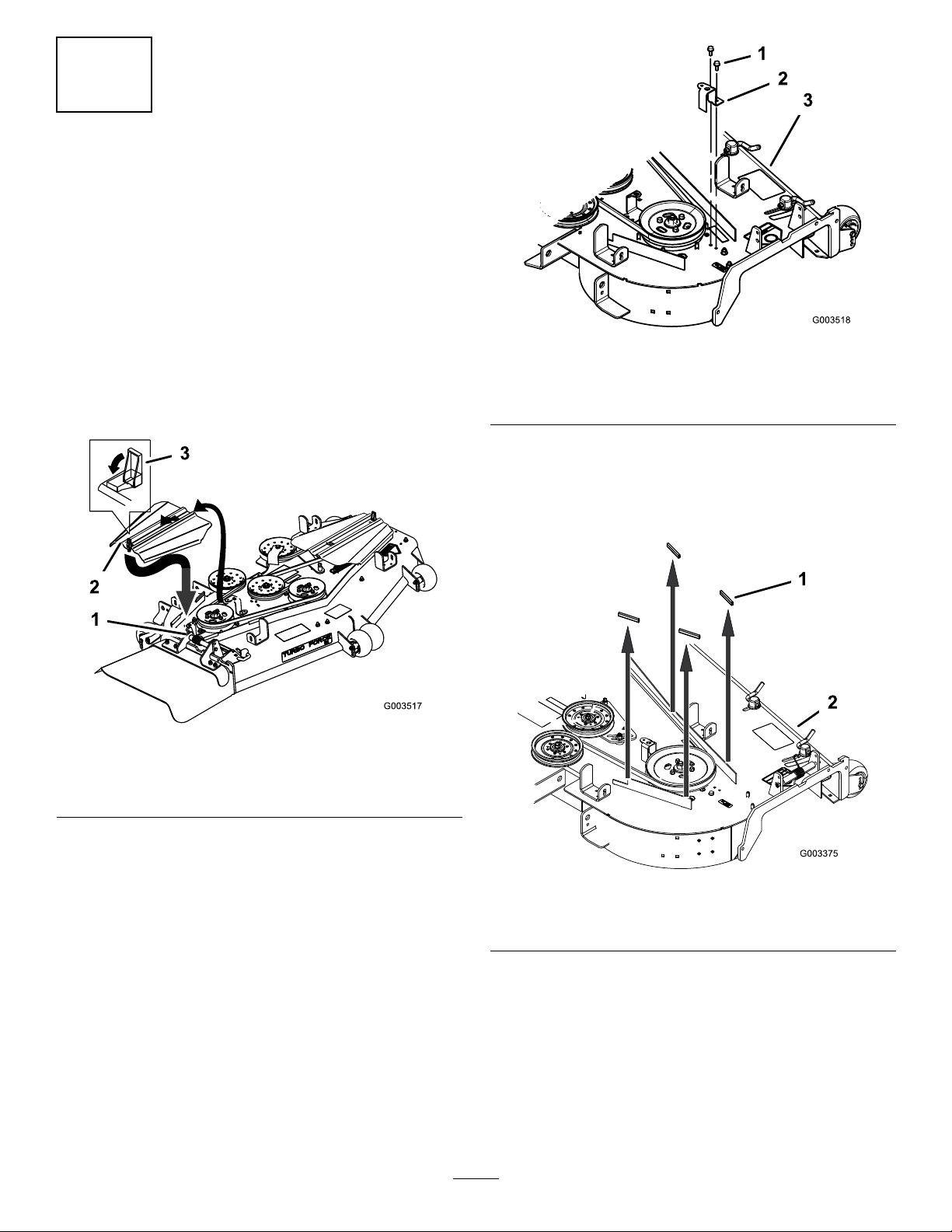
2.Unlatchandremovetherightbeltcover(Figure1).
Savethishardware.
Figure2
1.Selfthreadingbolt
2.Right-handbeltcover
bracket
4.Storetherightbeltcoverforlateruse.Ifthebagger
blowerandpulleyisremoveditcanbereused.
5.For72inchmowerdecksonly,removethe4rubber
stopsfromthemowerdeck(Figure3).
3.Mowerdeck
Figure1
1.Righthandbeltcover
bracket
2.Beltcover
3.Removetheoutsideright-handbeltcoverbracket
(Figure1).
3.Latch
1.Rubberstop(72inch
mowersonly)
Figure3
2.Mowerdeck
2
Page 3
3
InstallingthePulleyAssembly
Partsneededforthisprocedure:
1Pulleyassembly
Procedure
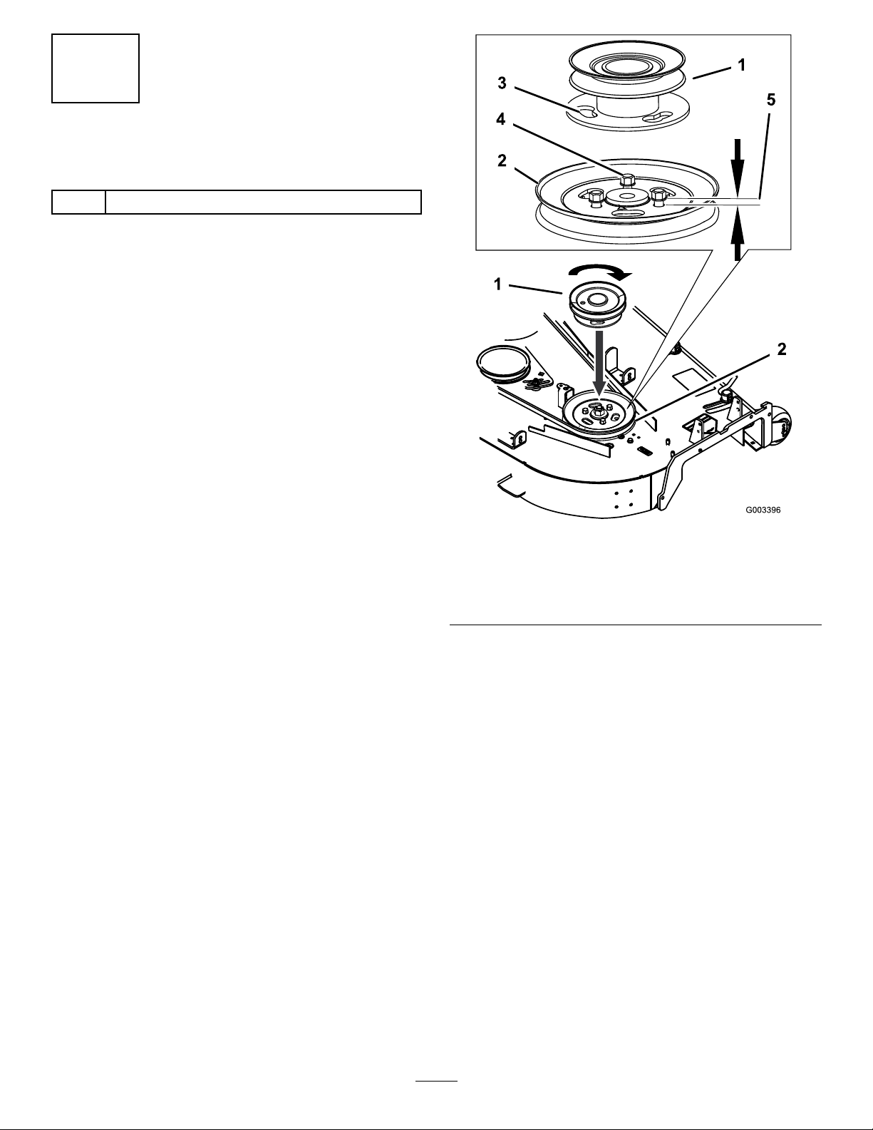
1.Loosen,butdonotremove,thetappingboltsonthe
existingmowerdeckpulley(Figure4).Thereshould
bea3/16inch(5mm)clearancebetweenthebolt
headandpulley .
2.Alignthenewpulleyassemblysothattheopenings
toverthepulleyboltheads(Figure4).
3.Turnthepulleytolockitintoposition(Figure4).
Note:Ifthepulleydoesnotturn,loosenthebolts
moretoraisetheboltheadsandallowthepulleyto
lockintoposition.
4.Afterthenewpulleyassemblyisinposition,tighten
theexistingboltstosecurenewpulleyassembly .
Note:Torquetheboltsto23ft-lb±2ft-lb(31
N-m±3N-m).
1.Pulley
assembly
2.Mowerdeck
pulley
Figure4
3.Lockingslots
4.Boltheads
5.3/16inch
(5mm)
3
Page 4

4
5
RemovingtheExisting
Anti-ScalpRollerandBracket
NoPartsRequired
Procedure
Note:Donotperformthisprocedureifapivotis
installed.
1.Cleantheareaaroundtheright,rearanti-scalpwheel.
2.Removetheanti-scalprollerfromthebracketby
looseningandremovingtheangenut(3/8inch)
andaxlebolt(3/8x4-1/2inch)asshowninFigure5.
Saveallhardwareforlateruse.
3.Removethethreecarriagebolts(3/8x3/4inch)and
angenuts(3/8inch)securingthebrackettothe
mower(Figure5).Saveallhardwareforlateruse.
InstallingtheBlowerPivotfor
a60inchBagger
Partsneededforthisprocedure:
1Blowerpivot
1Metaltemplate
3
Bolt(3/8x1inch)
3
Locknut(3/8inch)
Procedure
Note:Donotperformthisprocedureifapivotis
installed.
1.Installthemetaltemplate,withthenumber60in
it,tothemowerdeckwiththepreviouslyremoved
carriageboltsandnutsusingtheexistingholesinthe
mowerdeck(Figure6).
Makesurethecarriageboltsandnutsaretightand
thetemplateistightagainstthemowerdeck.
1.Anti-scalproller
2.Anti-scalpbracket
3.Bolt,(3/8x4–1/2inch)
2.Centerpunchthenewmowerdeckholelocations
usingthe3holesinthetemplate(Figure6).
3.Removethemetaltemplateanddrillthree,1/8inch
diameter,pilotholeswithasharpdrillbit(Figure6).
4.Drillthree,13/32inchdiameter,holesintothepilot
holeswithasharpdrillbit(Figure6).
Figure5
4.Carriagebolt,(3/8x3/4
inch)
5.Flangenut,(3/8inch)
6.Mowerdeck
4
Page 5

Figure6
1.Mowerdeck4.Templatelocationon
2.Drillthree,1/8inchpilot
holesand13/32inch
diameterholes,here
3.Templatewiththenumber
60init
mowerdeck
5.Nuts
6.Carriagebolts
5.Installthenewblowerpivotwith3bolts(3/8x1
inch)and3locknuts(3/8inch)usingthedrilled
holes(Figure7).
6.Installtheanti-scalprollertotheblowerpivotwith
thepreviouslyremoveaxlebolt(3/8x4-1/2inches),
spacer,bushing,andangenut(3/8inch)(Figure7).
6
InstallingtheBlowerPivotfor
a72inchBagger
Partsneededforthisprocedure:
1Blowerpivot
1Metaltemplate
4
Bolt(3/8x1inch)
4
Locknut(3/8inch)
Procedure
Note:Donotperformthisprocedureifapivotis
installed.
1.Installthemetaltemplate,withthenumber72in
it,tothemowerdeckwiththepreviouslyremoved
carriageboltsandnutsusingtheexistingholesinthe
mowerdeck(Figure8).
Makesurethecarriageboltsandnutsaretightand
thetemplateistightagainstthemowerdeck.
2.Centerpunchthenewmowerdeckholelocations
usingthe4holesinthetemplate(Figure8).
3.Removethemetaltemplateanddrillfour,1/8inch
diameter,pilotholeswithasharpdrillbit(Figure8).
1.Mowerdeck
2.Bolt,(3/8x1
inch)
3.Locknut,(3/8
inch)
Figure7
4.Bolt,(3/8x
4–1/2inch)
5.Spacer
6.Anti-scalproller9.Drilledholes
7.Bushing
8.Blowerpivot
4.Drillfour,13/32inchdiameter,holesintothepilot
holeswithasharpdrillbit(Figure8).
assembly
5
Page 6

Figure8
1.Mowerdeck4.Templatelocationon
2.Drillfour,1/8inchpilot
holesand13/32inch
diameterholes,here
3.Templatewiththenumber
72init
mowerdeck
5.Nuts
6.Carriagebolts
Figure9
1.Mowerdeck6.Anti-scalproller
2.Bolt,(3/8x1inch)
3.Flangenut,(3/8inch)
4.Bolt,(3/8x4–1/2inch)9.Carriagebolt,(3/8x3/4
5.Blowerpivotassembly
7.Bushing
8.Anti-scalpbracket
inch)
10.Spacer
5.Installthenewblowerpivotwith4bolts(3/8x1
inch)and4locknuts(3/8inch)usingthedrilled
holes(Figure9).
6.Installtheanti-scalprollerbracketwiththepreviously
removedcarriageboltsandnutstothemowerdeck
(Figure9).
7.Installtheanti-scalprollertothebracketwiththe
previouslyremoveaxlebolt(3/8x4-1/2inches),
bushings,andangenut(3/8inch)(Figure9).
7
InstallingtheBlower
Assembly,BaggerBelt,
SpringandBlowerBeltCover
Partsneededforthisprocedure:
1Blowerassembly
1Baggerbelt
1Blowerbeltcover
1
Spring
Procedure
RefertothebaggerOperator’sManualforthecorrect
proceduretoinstalltheblower,baggerbelt,spring,and
blowerbeltcover.
6
Page 7

Notes:
7
Page 8

 Loading...