

Page 1
Form No. 3355-379 Rev B
Blower and Drive Kit
For 52in E-Z Vac® Bagger for Z400 and Z500 Series Z
Master® Mowers
Model No. 78537 —Serial No. 260000001 and Up
Installation Instructions
Note: Deter mine the left and right sides of the mac hine from the nor mal operating position.
Loose Parts
Use the chart below to verify that all parts have been shipped.
Step
1
2
3
4
5
6
No parts required
No parts required
No parts required
Pulley assembly
Pivot bracket
Metal template
Bolt (3/8 x 1 inch)
Locknut (3/8 inch)
Blower assembly
Bagger belt
Blower belt cover
Description
Qty.
–
–
–
1
1
1
3
3
1
1
1
Verify an existing pivot tube.
Prepare the mower and remove the
belt cover.
Remove the existing anti-scalp
roller and bracket.
Install the pulley assembly.
Install the pivot bracket.
Install the blower, bagger belt,
spring, and belt cover.
Use
Step
1
Verifying an Existing Pivot
Tube
No Parts Required
Procedure
If y our mo w er has a pi v ot tube as sho wn in Figure
1 , then proceed to Ste p 6 and the Operator’ s
Man ual to install the blo w er assembly .
Note: Do not remo v e the existing pi v ot tube .
© 2006—The Toro® Company
8111 Lyndale Avenue South
Bloomington, MN 55420
Register at www.Toro.com. Original Instructions (EN)
Figure 1
1. Z400 mower deck 3. Z500 mower deck
2. Pivot tube 4. Pivot tube
Printed in the USA.
All Rights Reserved
Page 2
Step
2
Preparing the Mower and
Remove the Belt Cover
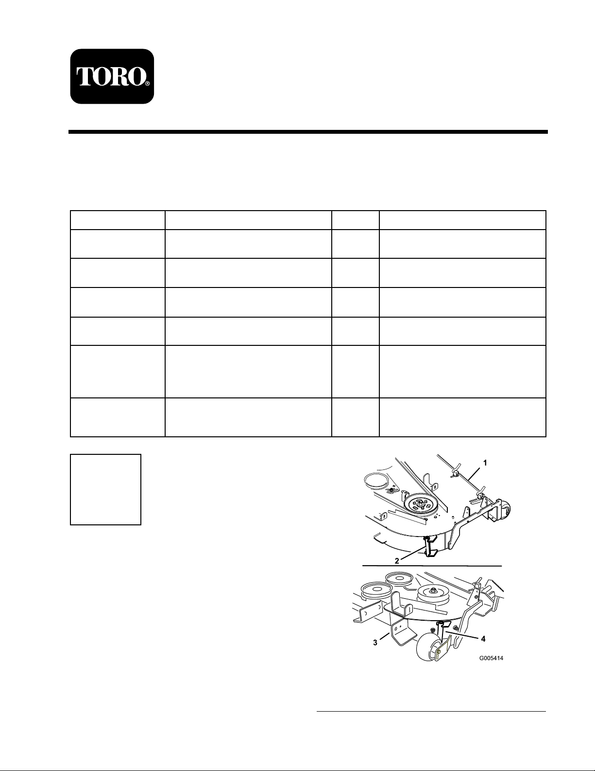
1. R emo v e the anti-scalp roller from the brac k et
b y loosening and remo ving the flang e n ut (3/8
inc h) and axle bolt (3/8 x 4-1/2 inc h) as sho wn
in Figure 2 .
2. R emo v e the three car riag e bolts (3/8 x 3/4
inc h) and flang e n uts (3/8 inc h) securing the
brac k et to the mo w er ( Figure 2 ). Sa v e the
fasteners for later use .
No Parts Required
Procedure
P erfor m the follo wing procedure to pre pare the
mo w er for attac hing the blo w er and finishing kit.
1. Diseng ag e the PTO , mo v e the motion control
lev ers to the neutral loc k ed position and set
the parking brak e .
2. Stop the engine , remo v e the k ey , and w ait for
all mo ving par ts to stop before lea ving the
operating position.
3. R e pair all bent or damag ed areas of mo w er
dec k and re place any missing par ts .
4. Clean the mo w er of any debris on the dec k or
rear par t of the mo w er to ease installation.
Note: Clean the area around the belt co v er
before remo ving .
5. Unlatc h and remo v e the right belt co v er . Sa v e
this hardw are .
6. Store the right belt co v er for later use . If the
bag g er blo w er and pulley is remo v ed it can be
reused.
3. R emo v e the brac k et and discard.
1. Anti-scalp roller
2. Anti-scalp bracket
3. Bolt, (3/8 x 4–1/2 inch)
Figure 2
4. Carriage bolt, (3/8 x 3/4
inch)
5. Flange nut, (3/8 inch)
6. Mower deck
Step
3
Removing the Existing
Anti-Scalp Roller and
Bracket
No Parts Required
Procedure
Note: Clean the area around the right, rear
anti-scalp wheel.
Step
4
Installing the Pulley
Assembly
Parts needed for this step:
1
Pulley assembly
Procedure
1. Lo w er the mo w er dec k to the lo w est
height-of-cut position.
2
Page 3

2. Loosen, but do not remo v e , the tapping bolts
on the existing mo w er dec k pulley ( Figure 3 ).
T here should be a 3/16 inc h (5 mm) clearance
betw een the bolt head and pulley .
3. Align the new pulley assembly so that the
openings fit o v er the pulley bolt heads ( Figure
3 ).
4. T ur n the pulley to loc k it into position ( Figure
3 ).
Note: If the pulley does not tur n, loosen
the bolts to raise the bolt heads and allo w the
pulley to loc k into position.
5. After the new pulley assembly is in position,
tighten the existing bolts to secure new pulley
assembly .
Note: T or que the bolts to 23 ft-lb ± 2 ft-lb
(31 N ⋅ m ± 3 N ⋅ m).
Figure 4
1. Bolt 3. Mower deck
2. Belt cover support bracket
Figure 3
1. Pulley assembly 4. Bolt heads
2. Mower deck pulley
3. Locking slots
5. 3/16 inch (5mm)
6. R emo v e the belt co v er suppor t brac k et from
the mo w er dec k ( Figure 4 ).
Step
5
Installing the Pivot Bracket
Parts needed for this step:
1
Pivot bracket
1
Metal template
3
Bolt (3/8 x 1 inch)
3
Locknut (3/8 inch)
Procedure
1. Install the metal template , with the n umber 52
in it, to the mo w er dec k with the previously
remo v ed car riag e bolts and n uts using the
existing holes in the mo w er dec k ( Figure 5 ).
Mak e sure the car riag e bolts and n uts are tight
and the template is tight ag ainst the mo w er
dec k.
2. Center punc h the new mo w er dec k hole
locations using the 3 holes in the template
( Figure 5 ).
3. R emo v e the metal template and drill three , 1/8
inc h diameter , pilot holes with a shar p drill bit
( Figure 5 ).
3
Page 4

4. Drill three , 13/32 inc h diameter , holes into the
pilot holes with a shar p drill bit ( Figure 5 ).
5. R emo v e par t of the metal belt co v er suppor t
on top of the mo w er . R efer to Figure 5 for the
cor rect size and location to remo v e .
Figure 5
1. Cut 1 inch (25 mm) off the
metal belt cover support
here
2. Mower deck 6. Carriage bolts
3. Drill three, 1/8 inch pilot
holes and 13/32 inch
diameter holes, here
4. Template with the number
52 in it
5. Template location on
mower deck
7. Lock nuts
1. Mower deck
2. Bolt, (3/8 x 1
inch)
3. Locknut, (3/8
inch)
Step
6
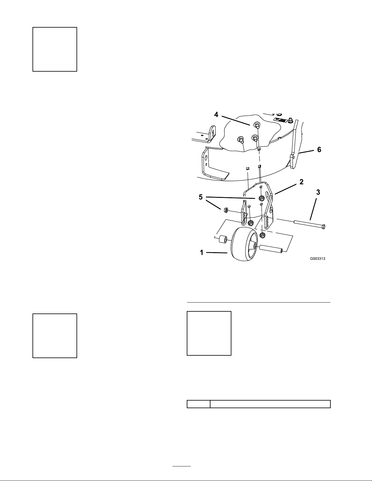
Figure 6
4. Bolt, (3/8 x
4–1/2 inch)
5. Spacer
6. Anti-scalp roller 9. Drilled holes
7. Bushing
8. Blower pivot
assembly
6. Install the new blo w er pi v ot assembly using
the 3 bolts (3/8 x 1 inc h) and 3 loc kn uts (3/8
inc h) ( Figure 6 ).
7. Install the anti-scalp roller with the axle bolt
(3/8 x 4-1/2 inc hes), flang e n ut (3/8 inc h)
( Figure 6 ).
Installing the Blower
Assembly, Bagger Belt,
Spring, and Blower Belt
Cover
Parts needed for this step:
1
Blower assembly
1
Bagger belt
1
Blower belt cover
Procedure
R efer to the bag g er Operator’ s Manual for the
cor rect procedure to install the blo w er , bag g er
belt, spring, and blo w er belt co v er .
4
 Loading...