

Page 1
FormNo.3395-266RevA
60inor72inE-ZVac
Z500SeriesZMaster
ModelNo.78534—SerialNo.315000001andUp
ModelNo.78535—SerialNo.315000001andUp
®
Mowers
™
Bagger
Registeratwww.T oro.com.
OriginalInstructions(EN)
*3395-266*A
Page 2
WARNING
CALIFORNIA
Proposition65Warning
Thisproductcontainsachemicalorchemicals
knowntotheStateofCaliforniatocausecancer,
birthdefects,orreproductiveharm.
Introduction
Readthisinformationcarefullytolearnhowtooperateand
maintainyourproductproperlyandtoavoidinjuryand
productdamage.Youareresponsibleforoperatingthe
productproperlyandsafely.
YoumaycontactTorodirectlyatwww .Toro.comforproduct
safetyandoperationtrainingmaterials,accessoryinformation,
helpndingadealer,ortoregisteryourproduct.
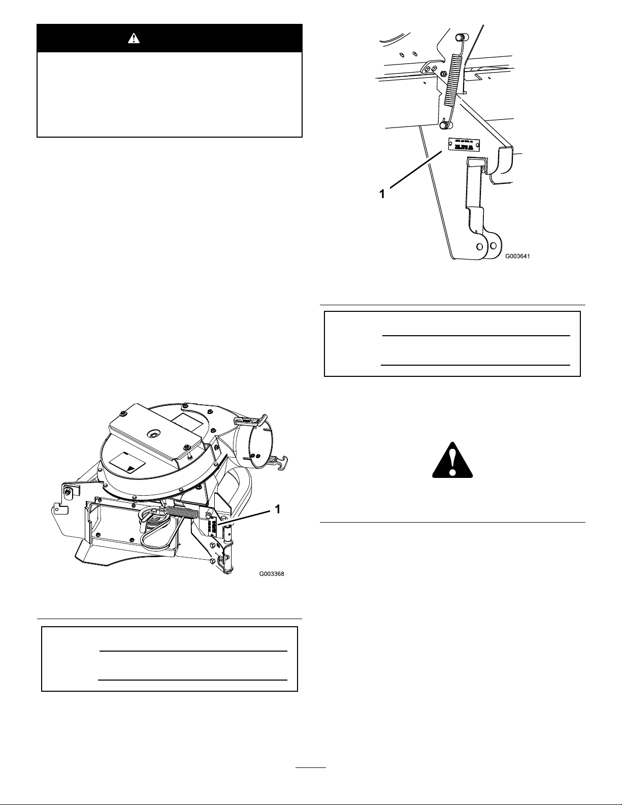
Figure2
1.Baggermodelandserialnumberlocation
Wheneveryouneedservice,genuineT oroparts,oradditional
information,contactanAuthorizedServiceDealerorToro
CustomerServiceandhavethemodelandserialnumbersof
yourproductready.Figure1identiesthelocationofthe
modelandserialnumbersontheproduct.Writethenumbers
inthespaceprovided.
Figure1
1.Blowermodelandserialnumberlocation
ModelNo.
SerialNo.
Thismanualidentiespotentialhazardsandhassafety
messagesidentiedbythesafetyalertsymbol(Figure3),
whichsignalsahazardthatmaycauseseriousinjuryordeath
ifyoudonotfollowtherecommendedprecautions.
Figure3
1.Safetyalertsymbol
Thismanualuses2wordstohighlightinformation.
Importantcallsattentiontospecialmechanicalinformation
andNoteemphasizesgeneralinformationworthyofspecial
attention.
Contents
ModelNo.
SerialNo.
©2015—TheToro®Company
8111LyndaleAvenueSouth
Bloomington,MN55420
Safety...........................................................................3
SafetyandInstructionalDecals.................................4
Setup............................................................................5
1PreparingtheMachine...........................................6
2InstallingtheBaggerMountingBracket....................6
3TighteningallMountingBolts.................................8
4InstallingtheHoodAssemblyandBags....................8
5RoutingtheBaggerBeltintotheBlower
Assembly............................................................9
Contactusatwww.Toro.com.
2
PrintedintheUSA
AllRightsReserved
Page 3

6InstallingtheBlowerAssembly...............................9
7SizingtheUpperTubefor60-inchMachineswith
GasEngines.......................................................11
8InstallingtheDischargeTubes...............................12
9InstallingtheBeltCover........................................15
10InstallingtheWeights..........................................15
11AdjustingtheParkingBrake.................................16
12CheckingtheTirePressure..................................16
Operation....................................................................17
PositioningtheAdjustableBafe..............................17
EmptyingtheGrassBags.........................................17
ClearingObstructionsfromtheBagger
System..............................................................18
RemovingtheBagger..............................................18
UsingtheGrassDeector.......................................19
TransportingtheMachine........................................19
OperatingTips......................................................19
Maintenance.................................................................21
RecommendedMaintenanceSchedule(s)......................21
CleaningtheHoodScreen.......................................21
CleaningtheBaggerandBags...................................21
InspectingtheBaggerBelt.......................................21
ReplacingtheBaggerBelt........................................21
CheckingandAdjustingtheBlowerLatch..................22
GreasingtheIdlerArm...........................................22
InspectingtheBagger.............................................22
InspectingtheMowerBlades...................................22
InstallingtheMowerBlades.....................................22
InstallingtheGrassDeector...................................23
Storage........................................................................24
Safety
ThefollowinglistcontainssafetyinformationspecictoToro
productsandothersafetyinformationyoumustknow .
•Becomefamiliarwiththesafeoperationoftheequipment,
withtheoperatorcontrols,andsafetysigns.
•Useextracarewithgrasscatchersorotherattachments.
Thesecanchangetheoperatingcharacteristicsandthe
stabilityofthemachine.
•Followthemanufacturer'srecommendationsforadding
orremovingwheelweightsorcounterweightstoimprove
stability.
•Donotuseagrasscatcheronsteepslopes.Aheavy
grasscatchercouldcauselossofcontroloroverturnthe
machine.
•Slowdownanduseextracareonhillsides.Besureto
travelintherecommendeddirectiononhillsides.Turf
conditionscanaffectthemachine'sstability.Useextreme
cautionwhileoperatingneardrop-offs.
•Keepallmovementonslopesslowandgradual.Donot
makesuddenchangesinspeed,directionsorturning.
•Thegrasscatchercanobstructtheviewtotherear.Use
extracarewhenoperatinginreverse.
•Usecarewhenloadingorunloadingthemachineintoa
trailerortruck.
•Neveroperatewiththedischargedeectorraised,
removedoraltered,unlessusingagrasscatcher.
•Keephandsandfeetawayfrommovingparts.Donot
makeadjustmentswiththeenginerunning.
•Stoponlevelground,disengagedrives,chockorblock
wheels,shutoffenginebeforeleavingtheoperator's
positionforanyreasonincludingemptyingthegrass
catcheroruncloggingthechute.
•Ifyouremovethegrasscatcher,besuretoinstallany
dischargedeectororguardthatmighthavebeen
removedtoinstallthegrasscatcher.Donotoperatethe
machinewithouteithertheentiregrasscatcherorthe
grassdeectorinplace.
•Stoptheenginebeforeremovingthegrasscatcheror
uncloggingthechute.
•Donotleavegrassingrasscatcherforextendedperiods
oftime.
•Grasscatchercomponentsaresubjecttowear,damage
anddeterioration,whichcouldexposemovingpartsor
allowobjectstobethrown.Frequentlycheckcomponents
andreplacewithmanufacturer'srecommendedparts,
whennecessary.
3
Page 4
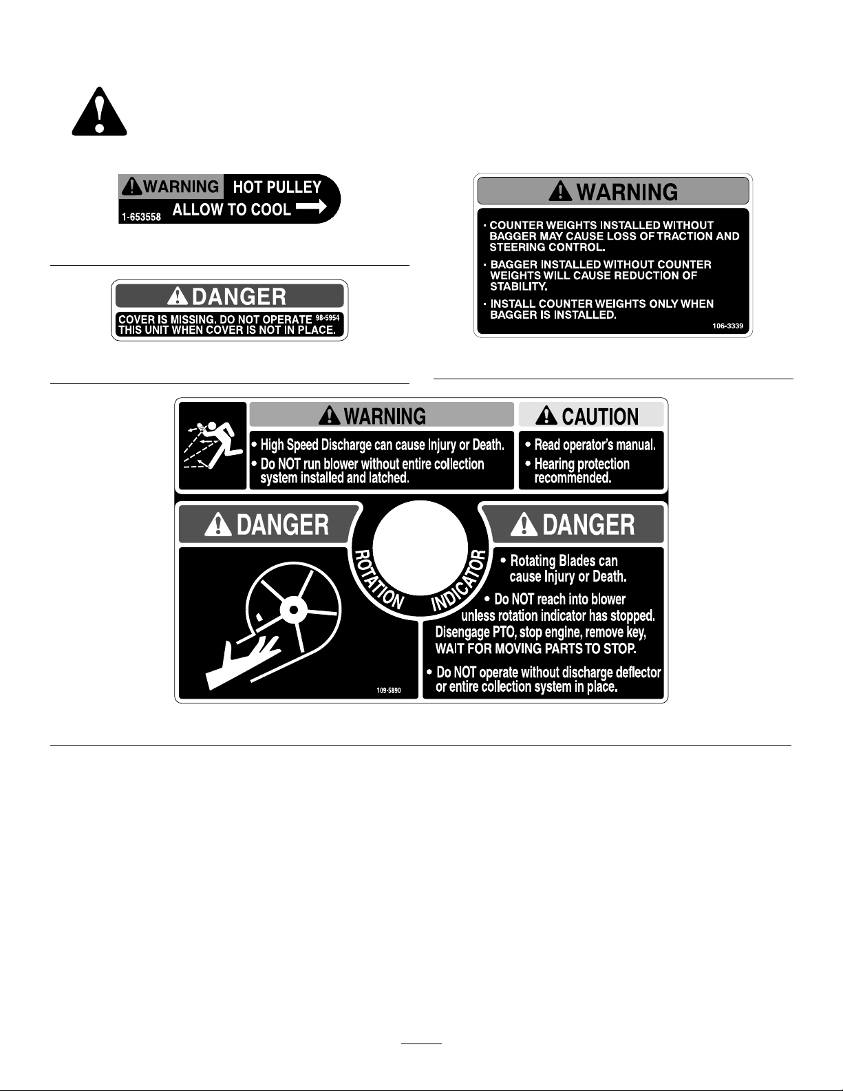
SafetyandInstructionalDecals
Safetydecalsandinstructionsareeasilyvisibletotheoperatorandarelocatednearanyareaofpotential
danger.Replaceanydecalthatisdamagedorlost.
1-653558
98-5954
109-5890
106-3339
4
Page 5

Setup
LooseParts
Usethechartbelowtoverifythatallpartshavebeenshipped.
ProcedureDescription
1
2
3
4
5
6
7
8
9
10
Nopartsrequired
Baggermountingbracket1
Baggersideplate2
Spacer
Bolt(3/8x1-1/2inches)
Bolt(3/8x1inch)(forZ593machines
only)
FlangeNut(3/8inch)
Curvedwasher
Nopartsrequired
Hoodassembly1
Bags3
Clevispin
Hairpincotter2
Baggerbelt(fromtheBlowerandDrive
Kit)
Blowerassembly(fromtheBlowerand
DriveKit)
Spring(fromtheBlowerandDriveKit)
Uppertube1
Uppertube1
Lowertube1
Bolt(#10x3/4inches)
Locknut(#10)
Washer(7/32inch)
Beltcover(fromtheBlowerandDrive
Kit)
Casterweight
U-bolt2
Nut(1/2inch)
Lockwasher(1/2inch)
Plate2
Topweight(for60inchmowerdecks
only)
Bolt,1/2x2–1/2inch-fortopweights
Qty.
–
2
14
2
14
14
–
2
1
1
1
3
3
3
1Installthebeltcover.
2
4
4
2
2
Preparethemachine.
Installthebaggermountingbracket.
Tightenallmountingbolts.
Installthehoodassemblyandbags.
Routethebaggerbeltintotheblower
assembly.
Installtheblowerassembly .
Sizetheuppertubefor60-inch
machineswithgasengines.
Installthedischargetubes.
Installtheweights.
Use
11
12
Note:Determinetheleftandrightsidesofthemachinefromthenormaloperatingposition.
Nopartsrequired
Nopartsrequired
5
–
–
Adjusttheparkingbrake.
Checkthetirepressure.
Page 6
3.Repeatthestepsabovefortheoppositeside(Figure
4,Figure5,andFigure6).
1
PreparingtheMachine
NoPartsRequired
Procedure
1.DisengagethePTO,movethemotioncontrollevers
totheNEUTRAL-LOCKEDpositionandsettheparking
brake.
2.Stoptheengine,removethekey,andwaitforallmoving
partstostopbeforeleavingtheoperatingposition.
3.Repairallbentordamagedareasofmowerdeckand
replaceanymissingparts.
4.Cleanthemachineofanydebrisonthedeckorrear
partofthemachinetoeaseinstallation.
2
Note:Makesurethecurvedwashersareinstalledas
showninFigure4,Figure5,andFigure6.
4.Installthebaggermountingbrackettotheleftandright
sidebaggerbracketswith4bolts(3/8x1-1/2inches),
4curvedwashers(3/8inch),and4angenuts(3/8
inch)asshowninFigure4,Figure5,andFigure6.
5.Installthebaggermountingbrackettotherearframe
ofthemachinewith2bolts(3/8x1-1/2inches)(use
2bolts(3/8x1inch)forZ593machinesasshownin
Figure5),2curvedwashers(3/8inch),and2ange
nuts(3/8inch)asshowninFigure4,Figure5,and
Figure6.
InstallingtheBaggerMounting Bracket
Partsneededforthisprocedure:
1Baggermountingbracket
2Baggersideplate
2
Spacer
14
Bolt(3/8x1-1/2inches)
2
Bolt(3/8x1inch)(forZ593machinesonly)
14
FlangeNut(3/8inch)
14
Curvedwasher
Procedure
Important:Donottightenanyboltsuntilbothside
bracketsandbaggermountingbracketaretlooseon
themachine.
Referto3TighteningallMountingBolts(page8)forthe
correctproceduretotightenthebolts.
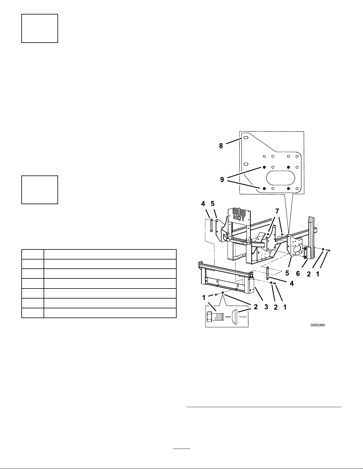
1.Removethebolts,nuts,andwashersholdingtheroll
bartoonesideofthemachine.Discardthenuts,bolts,
andwashers(Figure4,Figure5,andFigure6).
Figure4
ForZ500GasMowers
1.Bolt(3/8x1-1/2inches)6.ROPS
2.Curvedwasher(3/8inch)7.Flangenut(3/8inch)
3.Baggermountingbracket
4.Spacer9.Holesforinstallingthe
5.Baggersideplate
8.Sideviewofbaggerside
plate
sidebracket
2.Installthebaggersideplateandtherollbarsection
tothesideofthemachineusing4bolts(3/8x1-1/2
inches),4curvedwashers(3/8inch),and4angenuts
(3/8inch)asshowninFigure4,Figure5,andFigure6.
6
Page 7
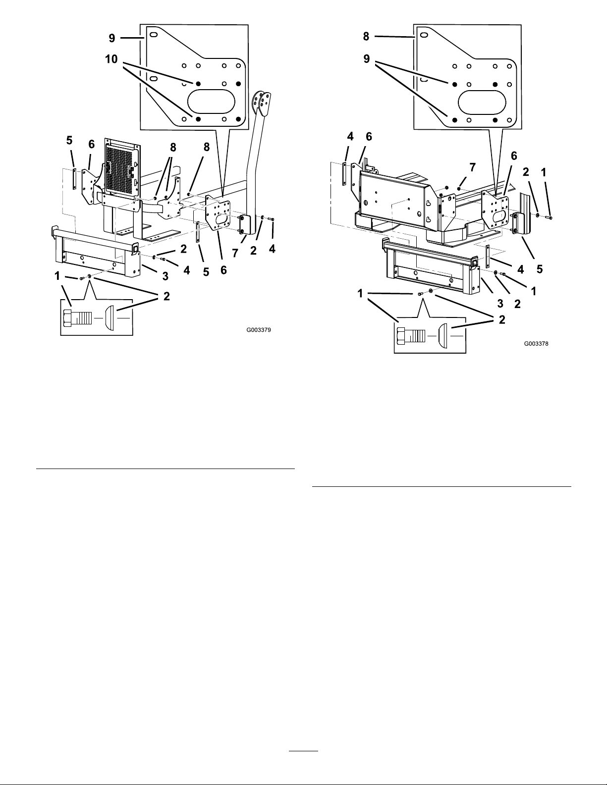
Figure5
ForZ593DieselMowers
1.Bolt(3/8x1inch)
2.Curvedwasher(3/8inch)7.ROPS
3.Baggermountingbracket
4.Bolt(3/8x1-1/2inches)9.Sideviewofbaggerside
5.Spacer10.Holesforinstallingthe
6.Baggersideplate
8.Flangenut(3/8inch)
plate
sidebracket
Figure6
ForZ597DieselMowers
1.Bolt(3/8x1-1/2inches)6.ROPS
2.Curvedwasher(3/8inch)7.Flangenut(3/8inch)
3.Baggermountingbracket
4.Spacer9.Holesforinstallingthe
5.Baggersideplate
8.Sideviewofbaggerside
plate
sidebracket
7
Page 8
3
TighteningallMountingBolts
NoPartsRequired
Procedure
Note:Allmountingboltsneedtobetorquedto48N-m
(35ft-lb).
1.Tightenthebaggermountingbrackettotherearframe
rst.
2.TightentheROPSandsidebracketstothesideofthe
machine.
3.Ifthebaggermountingbracketmovessidetoside
0.32cm(1/8inch)ormore,installoneorbothofthe
spacersbetweenthebaggermountingbracketand
mountingplates(Figure4,Figure5,andFigure6).
4.Tightenthebaggermountingbrackettotheside
brackets.
4
InstallingtheHoodAssembly andBags
Partsneededforthisprocedure:
1Hoodassembly
3Bags
2
Clevispin
2Hairpincotter
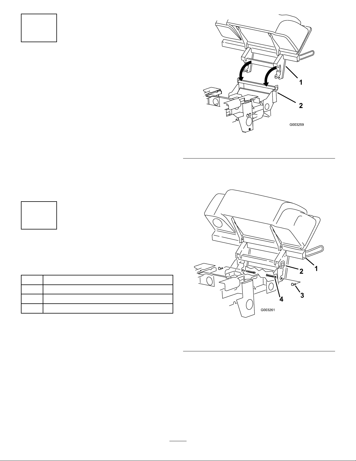
Figure7
1.Hoodassembly2.Baggermountingbracket
2.Installthe2clevispinsintothehoodassemblyand
baggermountingbracket.Securethemwith2hairpin
cotters(Figure8).
Procedure
1.Installthehoodassemblyontothebaggermounting
bracket(Figure7).
Figure8
1.Hoodassembly3.Hairpincotter
2.Baggermountingbracket
3.Installthebagtabintothenotchinthehoodassembly.
Dothisforallbags(Figure9).
Note:Thebagswillrestonthebaggerframe.
8
4.Clevispin
Page 9
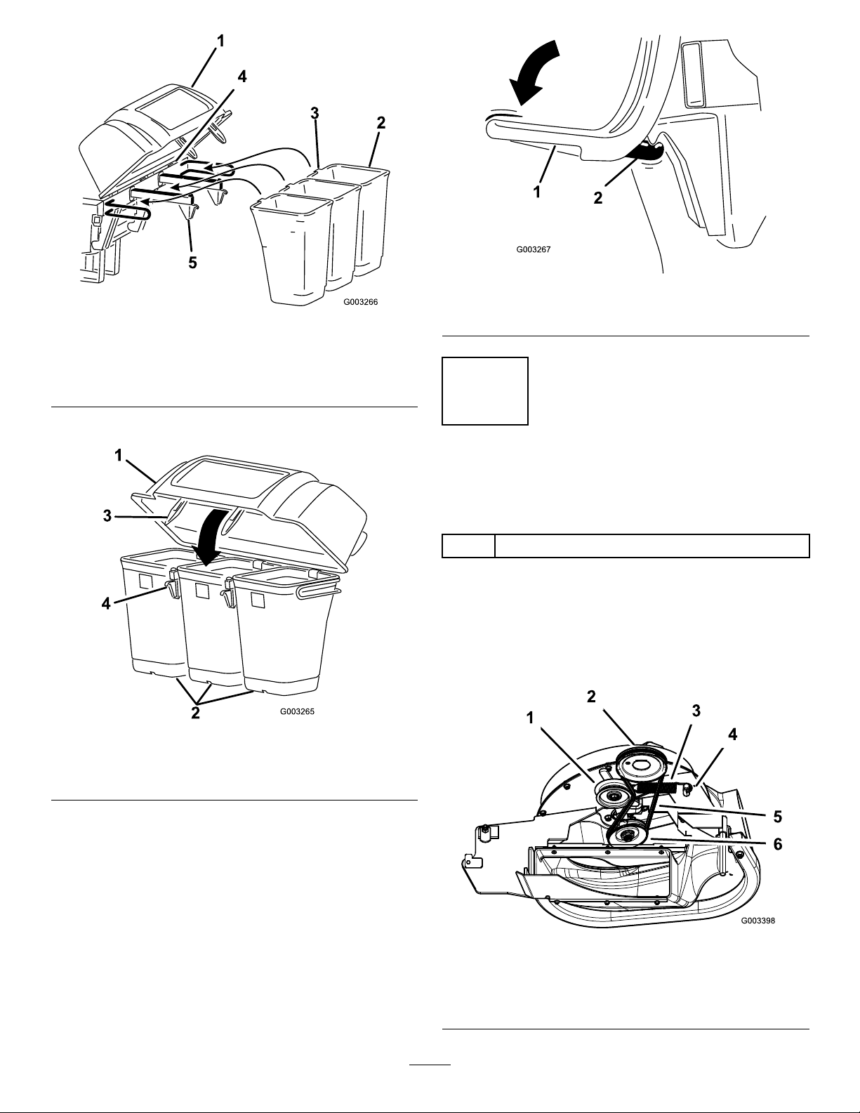
Figure11
Figure9
1.Hoodassembly4.Notch
2.Bag
3.Bagtab
4.Lowerthebaggerhoodoverthebags(Figure10).
5.Baggerframe
1.Baggerlatch2.Latchhook
5
RoutingtheBaggerBeltinto theBlowerAssembly
Partsneededforthisprocedure:
1
Baggerbelt(fromtheBlowerandDriveKit)
Procedure
1.Installthebeltaroundtheblowerpulley(Figure12).
2.Installthespringtotheidlerarmandthepegonthe
blowerassembly(Figure12).
Figure10
1.Hood3.Baggerlatch
2.Bag4.Latchhook
5.Positionthebaggerlatchunderthelatchhook(Figure
11).
6.Pushdownonthebaggerlatchuntilitlocksintoplace
(Figure11).
1.Idlerpulley4.Peg
2.Mower-deckpulley5.Belt
3.Spring
9
Figure12
6.Blowerpulley
Page 10

6
InstallingtheBlowerAssembly
Partsneededforthisprocedure:
1
Blowerassembly(fromtheBlowerandDriveKit)
1
Spring(fromtheBlowerandDriveKit)
Procedure
WARNING
Anuncovereddischargeopeningcouldallowthe
machinetothrowobjectsintheoperator'sor
bystander'sdirectionandresultinseriousinjury.
Also,contactwiththebladecouldoccur.
•Neveroperatethemachineunlessyouinstalla
coverplate,amulchplate,oragrasschuteand
catcher.
•Makesurethegrassdeectorisinstalledwhen
thegrasschuteandcatcherareremoved.
1.Removethesidedischargechutefromthemowerdeck
(Figure13).
Figure14
60-inchMowerDeck
1.Blowerassembly3.Pivothole
2.Mowerdeck4.Blowerassemblypeg
Figure13
1.Bolt
2.Spacer6.GrassDeector
3.Locknut
4.Spring8.J-hookendofspring
2.Slidetheblowerassemblypegintothepivothole.For
60-inchmachinesrefertoFigure14andfor72-inch
machinesrefertoFigure15.
5.Springinstalled
7.L-endofspring,place
behinddeckedgebefore
installingbolt
10
Page 11

Figure17
Figure15
72-inchMowerDeck
1.Blowerassembly3.Pivothole
2.Mowerdeck4.Blower-assemblypeg
3.Closetheblowerassemblytoseeifthelatchesare
adjustedcorrectly(Figure16).
Note:Loosenortightentheboltsothelatchesrmly
holdtheblowerassemblyagainstthemowerdeckbut
canbereleasedbyhand.
1.Spring-loadedidlerpulley
2.Short-hookend
3.Long-hookend
5.Pullthespring-loadedidlerpulleybackandroutethe
beltaroundthemower-deckpulley(Figure18).
Note:Ensurethatthebeltisroutedaroundtheblower
pulleyscorrectly.
Figure18
Figure16
1.Latch3.Blowerassembly
2.Bolt
4.InstallthespringasshowninFigure17.
Note:Makesurethatthehooksareinthecorrect
position.
1.Mower-deckpulley3.Blower
2.Spring-loadedIdlerpulley
11
Page 12

7
SizingtheUpperTubefor
60-inchMachineswithGas
Engines
Partsneededforthisprocedure:
1Uppertube
Procedure
Note:Thisprocedureisfor60-inchmachineswithgas
enginesonly.
1.Measureup89mm(3-1/2inches)fromthebottomof
theuppertube.Usetheexisting3holesasmarksand
thenmarkitinseveralplacestocreatealinearound
thetube(Figure19).
2.Cutthe89mm(3-1/2inches)offtheuppertube
(Figure19).
Note:Noticethe3indentationsinthetube.Thisis
whereholeswillbedrilledinthefollowingprocedure.
Figure19
1.Indentationsfordrilling
holes
2.Uppertube5.Linetocuttube
3.Cutoff89mm(3-1/2
inches)for60-inch
machineswithgasengines
only
4.Usetheexistingholesto
createaline
8
InstallingtheDischargeTubes
Partsneededforthisprocedure:
1Uppertube
1Lowertube
3
Bolt(#10x3/4inches)
3
Locknut(#10)
3
Washer(7/32inch)
Procedure
Important:Makesurethatthemowerdeckisin
thelowestheight-of-cutpositionwhileinstallingthe
dischargetubes.
Note:Remembertoreplacethegrassdeectorwhenthe
baggerisremovedfromthemachine.RefertoInstallingthe
GrassDeector(page23).
12
Page 13

1.DisengagethePTOandsettheparkingbrake.
2.Stoptheengine,removethekey,andwaitforallmoving
partstostopbeforeleavingtheoperatingposition.
3.Lowerthemowerdecktothelowestheight-of-cut
position.
4.Removethebagsforviewingthetubeunderthehood.
5.Installtheuppertubeintothebaggeropeningand
pullitbackoutsotherubbersealisprotrudingout
(Figure20).
Figure21
Figure20
1.Uppertube3.Baggerhood
2.Baggeropening
6.Withthehoodinthedownposition,measurethe
distancethetubeisinsidethehood.
Note:Measurefromthehoodplatetotheedgeof
thetubeasshowninFigure21.Thisdistanceneeds
tobe19mm(3/4inch).
1.Hoodplate
2.Uppertube
3.Hoodinthedownposition
4.19mm(3/4inch)
5.Edgeoftube
7.Oncethe19mm(3/4inch)measurementhasbeen
achieved,marktheuppertubeontheoutsidewhere
therubbersealprotrudesout(Figure22).
Note:Thisistoensurethecorrectpositionforthe
uppertubewhendrillingtheholesandconnectingthe
upperandlowertubes.Therubbersealmustprotrude
outfromthebaggerhood.
Figure22
1.Uppertube3.Baggerhood
2.Rubbersealprotrudingout4.Markhereagainstthe
rubberseal
8.Installthelowertubeintotheuppertube(Figure23).
13
Page 14

Figure23
1.Lowertube2.Uppertube
9.Slidethelowertubeontothebootandlatchthem
together(Figure24).
10.Makesurethatthemowerdeckisinthelowest
height-of-cutposition.
11.ChecktomakesurethatthemarkfromFigure22is
stillinplace.
12.Usingthe3holesorindentationsintheuppertubeasa
template,drill3holes(7/32inchdiameter)wherethe
upperandlowertubesjointogether(Figure25).
Note:Thereisalatchonthetopandbottomofthe
blowerhousing.
Figure25
1.Baggerhood4.Lowertube
2.Uppertube5.Blowerassembly
3.Drill7/32inchdiameter
holeshere(useuppertube
asatemplate)
13.Removethelowertubefromtheblower.
14.Jointheupperandlowertubeswith3bolts(#10x
3/4inches),3atwashers(7/32inch),and3locknuts
(#10)asshowninFigure26.
Figure24
1.Blowerassembly3.Latch
2.Lowertube
14
Page 15

Figure27
Figure26
1.Lowertube
2.Uppertube
3.Flatwasher(7/32inch)
15.Installthelowertubeontotheblowerhousingand
secureitwiththelatches.
16.Installthebagsontothebagger.
4.Locknut(#10)
5.Bolt(#10x3/4inches)
9
InstallingtheBeltCover
Partsneededforthisprocedure:
1
Beltcover(fromtheBlowerandDriveKit)
Procedure
1.Beltcover5.Latch
2.Blowerassembly6.Belt-covernotch
3.Pulleyassembly7.Belt-coversupport
4.Belt-coverbracket
10
InstallingtheWeights
Partsneededforthisprocedure:
2
Casterweight
2U-bolt
4
Nut(1/2inch)
4
Lockwasher(1/2inch)
2Plate
2
Topweight(for60inchmowerdecksonly)
2
Bolt,1/2x2–1/2inch-fortopweights
1.Lowerthemowerdecktothelowestheight-of-cut
position.
2.Installthenewbeltcoversothenotchesonbothsides
gooverthebelt-coversupportsandsecurethelatch
(Figure27).
Procedure
TocomplywithANSI/OPEIB71.4-2012Standard,add
weightstothemachine.
CAUTION
Thebaggeraddsalotofweighttotherearofthe
machineandmaycauseanunstableconditionthat
couldresultinalossofcontrol.
1.Placecasterweightsonthefrontcasters.
15
Page 16

2.Install1plate,2nuts(1/2inch)and2lockwashers
(1/2inch)undertheframeandweight(Figure28).
3.Repeatfortheoppositeside.
Note:AllZMastermachinesreceivethecaster
weights.
Figure28
1.Frontcasterweight4.Nut
2.U-bolt5.Frontcaster
3.Plate6.Lockwasher
11
AdjustingtheParkingBrake
NoPartsRequired
Procedure
Checktomakesuretheparkingbrakeisadjustedproperly.
RefertoyourOperator’ sManualforthecorrectprocedure.
12
CheckingtheTirePressure
NoPartsRequired
Procedure
Note:Increasethetirepressureduetotheadditionalweight.
Note:OnlyZMastermachineswith60-inchmower
decksreceivethetopweights.
4.Installthetopweightsontopofeachcasterweightfor
60-inchmachineswith2bolts(1/2x2–1/2inches)as
showninFigure29.
Figure29
1.Topweight3.Frontcasterweight
2.Bolt(1/2x2–1/2inches)
4.Frontcasterwheel
Checkandincreasetheairpressureinthefrontcasterwheels
andreartires(Figure30).
Pressure:Reartires—90kPa(20psi)
Frontcasterwheels—90kPa(25psi)
Figure30
16
Page 17

Operation
Note:Determinetheleftandrightsidesofthemachine
fromthenormaloperatingposition.
Important:Settheparkingbrakewhenleavingthe
machineunattended,evenifjustforafewminutes.
WARNING
CAUTION
Childrenorbystandersmaybeinjuredifthey
moveorattempttooperatethetractorwhileitis
unattended.
Alwaysremovetheignitionkeyandsettheparking
brakewhenleavingthemachineunattended,even
ifjustforafewminutes.
Toavoidpersonalinjury,followtheseprocedures:
•Becomefamiliarwithalloperatingandsafety
instructionsinthe
machinebeforeusingthisattachment.
•Neverremovethebaggerorbaggertubeswhile
theengineisrunning.
•Alwaysshuttheengineoffandwaitforall
movingpartstostopbeforeclearingan
obstructionfromthebaggingsystem.
•Neverdomaintenanceorrepairswhilethe
engineisrunning.
•Settheparkingbrake.
Operator's Man ual
foryour
WARNING
Withoutthegrassdeector,baggertubesor
completebaggerassemblymountedinplace,you
andothersareexposedtobladecontactandthrown
debris.Contactwiththerotatingmowerblade(s)
andthrowndebriswillcauseinjuryordeath.
PositioningtheAdjustable
Bafe
AdjustthebafetopositionB(middleposition)forbagging.
RefertotheOperatorManualforthemachine.
Figure31
•Alwaysinstallthegrassdeectorwhenremoving
thebaggerandchangingtosidedischarge
mode.
•Ifthegrassdeectoriseverdamaged,replaceit
immediately.Thegrassdeectorroutesmaterial
downtowardtheturf.
•Neverputyourhandsorfeetunderthemachine.
•Nevertrytoclearthedischargeareaormower
bladesunlessyoumovethepowertake-off
(PTO)tooffandrotatetheignitionkeytooff.
Alsoremovethekeyandpullthewireoffofthe
sparkplug(s).
•Turnofftheenginebeforeuncloggingthe
dischargechute.
EmptyingtheGrassBags
Grassbagsareheavywhenfull.Becarefulwhenliftingor
handlingagrassbagthatisfull.
1.DisengagethePTO,settheparkingbrake,andchock
orblockthetiresifonaslope.
2.Unlatchthebaggerlatch.
3.Openthebaggerhood.
4.Compressthedebrisintothebags.Withbothhands,
liftuponthebagandunhookitfromthebagger
bracket.
5.Grabthehandleonthebottomofthebagandtipit
overtoemptythebag(Figure32).
17
Page 18

5.Removethetubesfromthebagger.
6.Useastickorsimilarobject,notyourhands,toremove
andcleartheobstructionfromthetubeassembly .
Note:Inmostcases,thedebriscanbeshakenoutof
thetubes.
7.Iftheblowerassemblyisplugged,unlatchthebagger
blowerassembly,removethebelt,andswingitopen.
8.Useastickorsimilarobject,notyourhands,toremove
andcleartheobstructionfromtheblowerassembly.
9.Afteryouremovetheobstruction,installthecomplete
baggersystemandresumeoperation.
RemovingtheBagger
Figure32
1.Bag2.Bottomhandle
6.Repeatfortheotherbag.
7.Installthebagtabintothenotchinthebaggersupport
frame.
Note:Dothisforbothbags.
8.Lowerthebaggerhoodoverthebags.
9.Latchthebaggerhood.
ClearingObstructionsfrom theBaggerSystem
WARNING
Whenthebaggerisinoperation,theblowercanbe
rotatingandcutofforinjurehands.
•Beforeadjusting,cleaning,repairingand
inspectingtheblower,andbeforeunclogging
thechute,turnofftheengineandwaitforall
movingpartstostop.Removethekey .
•Useastick,notyourhands,toremovean
obstructionfromtheblowerandtube.
•Keepface,hands,feet,andanyotherpartof
yourbodyorclothingawayfromconcealed,
moving,orrotatingparts.
WARNING
Componentsaroundenginewillbehotifthe
machinehasbeenrunning.Touchinghot
componentscancauseburns.
•Donottouchenginecomponentswhenhot.
•Allowenginetocoolbeforeremovingthebagger.
1.DisengagethePTO,settheparkingbrake,andchock
orblockthetires.
2.Turnofftheengine,removethekey,andwaitforall
movingpartstostopbeforeleavingtheoperating
position.
3.Unlatchthelowertubefromtheblowerandremove
thetubefromtheblowerassembly.
4.Removethetubefromthebaggerhood.
5.Lowerthemowerdecktothelowestheight-of-cut
position.
6.Unlatchthebeltcoveroverthemowerpulleyassembly .
7.Removethebaggerbeltfromthemowerpulley
assembly.
8.Opentheblowerassembly.
9.Removetheblowerassemblyfromthepivothole.
10.Ifyouarechangingtosidedischargemode,ensure
thegrassdeectorisinstalledandcanbeloweredinto
workingposition.
11.Removethehoodandbagassembly.
1.DisengagethePTOandsettheparkingbrake.
2.Turnofftheengine,removethekey,andwaitforall
movingpartstostopbeforeleavingtheoperating
position.
3.Emptythebags.
4.Unlatchthelowertube.
18
Page 19

UsingtheGrassDeector
OperatingTips
DANGER
Withoutthegrassdeector,dischargecover,or
completegrasscatcherassemblymountedin
place,youandothersareexposedtobladecontact
andthrowndebris.Contactwithrotatingmower
blade(s)andthrowndebriswillcauseinjuryor
death.
•Alwaysinstallthegrassdeectorwhenremoving
thebaggerandchangingtosidedischarge
mode.
•Ifthegrassdeectoriseverdamaged,replaceit
immediately.Thegrassdeectorroutesmaterial
downtowardtheturf.
•Neverputyourhandsorfeetunderthemachine.
•Nevertrytoclearthedischargeareaormower
bladesunlessyoumovethepowertakeoff
(PTO)totheoffposition,rotatetheignitionkey
tooffandremovethekey.
TransportingtheMachine
Donotleavegrassordebrisinthebaggerwhiletransporting
themachine.
DANGER
MachineSize
Rememberthatthemachineislongerandwiderwiththis
attachmentinstalled.Byturningtoosharplyinconned
placesyoumaydamagetheattachmentorotherproperty.
Trimming
Alwaystrimwiththeleftsideofthemachine.Donottrim
withtherightsideofthemachinebecauseyoucoulddamage
thebaggingtubes.
CuttingHeight
Foroptimumbaggingperformance,setthedeckheight-of-cut
toremovenomorethan51to76mm(2to3inches)or
1/3ofthegrassheight,whicheverisless.Cuttingoffmore
thanthiswillreducethecapacityofthevacuumsystem.
CuttingFrequency
Cutthegrassoften,especiallywhenitgrowsrapidly.Youwill
havetocutyourgrasstwiceifitgetsexcessivelylong(referto
BaggingLongGrass(page19)).
CuttingTechnique
Forbestlawnappearance,besuretoslightlyoverlapthe
machineintothepreviouslycutarea.Thishelpsreducethe
loadontheengineandreducesthechanceofpluggingthe
blowerassemblyandtubes.
Transportingthemachinewithgrassordebrisin
thebaggercandamagethemachine.
Donotleavegrassordebrisinthebaggerwhile
transportingthemachine.
BaggingSpeed
Thebaggingsystemmayplugifyoudrivetoofastandthe
enginespeedgetstooslow .Onhillsitmaybenecessaryto
slowthemachinesgroundspeed.Mowdownhillwhenever
possible.
CAUTION
Asthebaggerlls,extraweightisaddedtotheback
ofthemachine.Ifyoustopandstartsuddenlyon
hills,youmaylosesteeringcontrolorthemachine
maytip.
•Donotstartorstopsuddenlywhengoinguphill
ordownhill.Avoiduphillstarts.
•Ifyoudostopthemachinewhengoinguphill,
disengagethePTO.Thenbackdownthehill
usingaslowspeed.
•Donotchangespeedsorstoponslopes.
BaggingLongGrass
Ifthegrassiseverallowedtogrowlongerthannormal,orif
itcontainsahighdegreeofmoisture,raisethecuttingheight
higherthanusualandcutandbagthegrassatthissetting.
19
Page 20

Thencutandbagthegrassagainusingthelower,normal
setting.
Excessivelylonggrassisheavyandmaynotbepropelled
completelyintothebagger.Ifthishappens,thetubeand
blowermayplug.Toavoidpluggingthebaggingsystem,mow
thegrassatahighheight-of-cut,thenlowerthemowerto
yournormalcuttingheightandrepeatthebaggingprocess.
BaggingWetGrass
Ifpossible,alwaystrytocutgrasswhenitisdry.Wetgrass
cancauseplugging.
ReducingPlugging
Toavoidpluggingthebaggingsystem,reducegroundspeed
andmowthegrassatahighheight-of-cut,thenlowerthe
mowertoyournormalcuttingheightandrepeatthebagging
process.
SignsofPlugging
Asyouarebagging,asmallamountofgrassclippings
normallyblowoutthefrontofthemachine.Anexcessive
amountofclippingblowoutindicatesthatthebaggerisfull
orthetubeisplugged.
BaggingBlades
Inmostmowingconditions,thestandardhighliftbladeswill
providethebestbaggingperformance.
TheToroAtomicbladeisrecommendedforbaggingleaves
indryconditions.Indrydustyconditions,themediumlift
orlowliftbladeswillreducedustanddirtblowoutwhile
providingeffectivebaggingairow .
ContactanAuthorizedServiceDealerfortheproperblades
fordifferentmowingconditions.
CurbClimbingandLoading
Alwaysliftthedecktothehighestpositionwhenloading
themachineontrailersorascending/descendingacurb.
Leavingthemowerinalowerpositioncancausedamageto
themachinewhileloadingandgoingoveracurb.Ifacurb
ishigherthan152mm(6inches),crossitatasharpangle
withthedeckfullyraised.Useextremecautionwhenloading
ontoatrailer.
20
Page 21

Maintenance
RecommendedMaintenanceSchedule(s)
MaintenanceService
Interval
Aftertherst8hours
Beforeeachuseordaily
Every25hours
Every50hours
Every100hours
MaintenanceProcedure
•Inspectthebaggerbelt.
•Inspectthebagger.
•Cleanthehoodscreen.
•Cleanthebagger.
•Inspectthebaggerbelt.
•Greasetheidlerarm.
•Inspectthebagger.
CleaningtheHoodScreen
ServiceInterval:Beforeeachuseordaily
Thescreensneedtobecleanedbeforeeachuse.Inwetgrass
theywillneedtobecleanedmoreoften.
1.Disengagethepowertakeoff(PTO)andsetthe
parkingbrake.
2.Turnofftheengine,removethekey,andwaitforall
movingpartstostopbeforeleavingtheoperating
position.
3.Openthebaggerhood.
4.Cleanthedebrisfromthescreen.
5.Closethebaggerhood.
ReplacingtheBaggerBelt
1.DisengagethePTO ,movethemotioncontrolleversto
theNEUTRAL-LOCKEDposition,andsettheparking
brake.
2.Stoptheengine,removethekey,andwaitforallmoving
partstostopbeforeleavingtheoperatingposition.
3.Pullbackonthespring-loadedidlerpulleytorelieve
thebelttension(Figure33).
4.Removetheexistingbaggerbeltfromthemower-deck
pulleyandthentheblowerpulleys.
5.Installthenewbeltaroundtheblowerpulleysandthe
mower-deckpulley(Figure33).
CleaningtheBaggerandBags
ServiceInterval:Beforeeachuseordaily
Thebaggerneedstobecleaneddaily.
1.Washtheinsideandoutsideofthebaggerhood,bags,
tube,andtheundersideofthemachine.Useamild
automotivedetergenttoremovedirt.
2.Makesureyouremovemattedgrassfromallparts.
3.Afterwashingallparts,letthemdrythoroughly.
Note:Withallpartsinstalled,startandrunthemachinefor
aminutetoassistindrying.
InspectingtheBaggerBelt
ServiceInterval:Aftertherst8hours
Every25hours
Checkbeltsforcracks,frayededges,burnmarksoranyother
damage.Replacedamagedbelts.
Figure33
1.Idlerpulley4.Peg
2.Mower-deckpulley5.Belt
3.Spring
6.InstallthespringasshowninFigure34.
6.Blowerpulley
21
Page 22

1.Springloadedidlerpulley
2.Shorthookend
Figure34
3.Longhookend
Figure36
7.Pullbackonthespring-loadedidlerpulleyandinstall
thebeltontothespring-loadedidlerpulley(Figure33).
CheckingandAdjustingthe BlowerLatch
Closetheblowerassemblytoseeifthelatchesareadjusted
correctly.Loosenortightentheboltssothelatchesrmly
holdtheblowerassemblyagainstthemowerdeck,butcanbe
releasedbyhand.
Figure35
1.Latch3.Blowerassembly
2.Bolt
InspectingtheBagger
ServiceInterval:Every100hours
Aftertherst8hours
Inspectthebaggerattachmentafterthersteighthoursof
operation,and100hoursthereafter.
1.DisengagethePTO ,movethemotioncontrolleversto
theNEUTRAL-LOCKEDposition,andsettheparking
brake.
2.Stoptheengine,removethekey,andwaitforallmoving
partstostopbeforeleavingtheoperatingposition.
3.Checktheuppertube,lowertube,baggerhood,and
theblowerassembly.Replacethesepartsiftheyare
crackedorbroken.
4.Checkthebags,baggerframe,andscreen.Replaceany
partsthatarecrackedorbroken.
5.Tightenallnutsboltsandscrews.
InspectingtheMowerBlades
1.Inspectthemowerbladesregularlyandwhenevera
bladestrikesaforeignobject.
2.Ifbladesarebadlywornordamaged,installnewblades.
RefertoyourmachineOperator'sManualforcomplete
blademaintenance.
GreasingtheIdlerArm
ServiceInterval:Every50hours
Greasethebaggerbeltidlerarm(Figure36)every50hours.
InstallingtheMowerBlades
Inmostmowingconditions,thestandardhighliftbladeswill
providethebestbaggingperformance.
TheToroAtomicbladeisrecommendedforbaggingleaves
indryconditions.Indrydustyconditions,themediumlift
orlowliftbladeswillreducedustanddirtblowoutwhile
providingeffectivebaggingairow .
22
Page 23

ContactanAuthorizedServiceDealerfortheproperblades
fordifferentmowingconditions.
RefertothemachineOperator'sManualformoreinformation
oninstallingblades.
InstallingtheGrassDeector
WARNING
Anuncovereddischargeopeningcouldallowthe
machinetothrowobjectsintheoperator'sor
bystander'sdirectionandresultinseriousinjury.
Also,contactwiththebladecouldoccur.
•Neveroperatethemachineunlessyouinstalla
coverplate,amulchplate,oragrasschuteand
catcher.
•Makesurethegrassdeectorisinthedown
position.
1.Removethelocknut,bolt,springandspacerholding
thedeectortothepivotbrackets(Figure37).
Figure37
1.Bolt
2.Spacer6.Grassdeector
3.Locknut
4.Spring8.J-hookendofspring
5.Spring(installed)
7.L-endofspring(placeit
behinddeckedgebefore
installingthebolt)
2.Removethedamagedorworngrassdeector.
3.Placethespacerandspringontothegrassdeector.
PlacetheL-endofthespringbehindthedeckedge.
Note:MakesuretheL-endofthespringisinstalled
behindthedeckedgebeforeinstallingtheboltas
showninFigure37
4.Installtheboltandnut.
5.PlacetheJ-hookendofthespringaroundthegrass
deector(Figure37).
Important:Thegrassdeectormustbeableto
lowerdownintoposition.Liftthedeectorupto
testthatitlowersintothefulldownposition.
23
Page 24

Storage
1.Cleanthebaggerattachment.RefertoCleaningthe
BaggerandBags(page21).
2.Inspectthebaggerattachmentfordamage.Referto
InspectingtheBagger(page22).
3.Makesurethatthebagsareemptyandthoroughlydry.
4.Checkthebeltforwearorcracks.
5.Storethemachineinaclean,dryplace,outofdirect
sunlight.Ifyoumuststorethemachineoutside,cover
itwithaweatherproofcover.Thisprotectstheplastic
partsandextendsthelifeofthemachine.
24
Page 25

Notes:
25
Page 26

Notes:
26
Page 27

Notes:
27
Page 28

TheToroTotalCoverageWarranty
ALimitedWarranty(seewarrantyperiodsbelow)Contractor
Landscape
Equipment
(LCE)
ConditionsandProductsCovered
TheToroCompanyanditsafliate,T oroW arrantyCompany,pursuanttoanagreement
betweenthem,jointlypromisetotheoriginalpurchasertorepairtheT oroProducts
listedbelowifdefectiveinmaterialsorworkmanship.
Thefollowingtimeperiodsapplyfromthedateofpurchasebytheoriginalowner:
ProductsWarrantyPeriod
21in.Mowers2yearsResidentialUse
1yearCommercialUse
4
•Engines
Honda–2years
Kawasaki–3years
30in.Mowers2yearsResidentialUse
1yearCommercialUse
4
•Engines
Mid-SizeWalk-BehindMowers
4
•Engines
GrandStand
4
•Engines
•Frame
®
ZMaster
•Engines
2000SeriesMowers
4
•Frame
®
ZMaster
•Engines
•Frame
ZMaster
•Engines
®
4
4
3000SeriesMowers
5000SeriesMowers
®
Mowers
Kawasaki–3years
2years
Kawasaki–3years
5yearsor1,200hours
3years
Lifetime(originalowneronly)
4yearsor500hours
3years
Lifetime(originalowneronly)
5yearsor1,200hours
3years
Lifetime(originalowneronly)
5yearsor1,200hours
KohlerCommand–2years
KohlerEFI–3years
•Frame
®
ZMaster
•Engines
6000SeriesMowers
4
•Frame
®
ZMaster
•Engines
7000SeriesMowers
4
•Frame
®
ZMaster
•Engines
8000SeriesMowers
4
•Frame
Lifetime(originalowneronly)
5yearsor1,200hours
Kawasaki–3years
Lifetime(originalowneronly)
5yearsor1,200hours
2years
Lifetime(originalowneronly)
2yearsor1,200hours
2years
Lifetime(originalowneronly)
AllMowers
•Battery90daysPartsandLabor
1yearPartsonly
•BeltsandTires90days
•Attachments1year
1
Residentialusemeansuseoftheproductonthesamelotasyourhome.Useatmorethanone
locationisconsideredcommercialuseandthecommercialwarrantywouldapply.
2
Whicheveroccursrst.
3
LifetimeFrameW arranty-Ifthemainframe,consistingofthepartsweldedtogethertoformthe
tractorstructurethatothercomponentssuchastheenginearesecuredto,cracksorbreaksin
normaluse,itwillberepairedorreplaced,atToro'soption,underwarrantyatnocostforpartsand
labor.Framefailureduetomisuseorabuseandfailureorrepairrequiredduetorustorcorrosion
arenotcovered.
4
SomeenginesusedonToroProductsarewarrantedbytheenginemanufacturer .
1
1
2
3
2
3
2
3
2
3
2
3
2
3
2
3
InstructionsforObtainingWarrantyService
IfyouthinkthatyourT oroProductcontainsadefectinmaterialsorworkmanship,
followthisprocedure:
1.ContactanyAuthorizedT oroServiceDealertoarrangeserviceattheir
dealership.T olocateadealerconvenienttoyou,refertotheYellowPagesof
yourtelephonedirectory(lookunder“LawnMowers”)oraccessourwebsite
atwww.Toro.com.Youmayalsocallthenumberslistedinitem#3tousethe
24-hourT oroDealerlocatorsystem.
2.Bringtheproductandyourproofofpurchase(salesreceipt)totheService
Dealer.Thedealerwilldiagnosetheproblemanddetermineifitiscovered
underwarranty.
3.IfforanyreasonyouaredissatisedwiththeServiceDealer’sanalysisorwith
theassistanceprovided,contactusat:
RLCCustomerCareDepartment
ToroWarrantyCompany
811 1LyndaleAvenueSouth
Bloomington,MN55420-1 196
888-865-5676(U.S.Customers)
888-865-5691(Canadacustomers)
OwnerResponsibilities
YoumustmaintainyourT oroProductbyfollowingthemaintenanceprocedures
describedintheOperator'sManual.Suchroutinemaintenance,whetherperformedby
adealerorbyyou,isatyourexpense.
ItemsandConditionsNotCovered
Thereisnootherexpresswarrantyexceptforspecialemissionsystemcoverage
andenginewarrantycoverageonsomeproducts.Thisexpresswarrantydoesnot
coverthefollowing:
•Costofregularmaintenanceserviceorparts,suchaslters,fuel,lubricants,oil
changes,sparkplugs,airltersbladesharpeningorwornblades,cable/linkage
adjustments,orbrakeandclutchadjustments
•Componentsfailingduetonormalwear
•Anyproductorpartwhichhasbeenalteredormisusedorneglectedandrequires
replacementorrepairduetoaccidentsorlackofpropermaintenance
•Pickupanddeliverycharges
•RepairsorattemptedrepairsbyanyoneotherthananAuthorizedT oroService
Dealer
•Repairsnecessaryduetofailuretofollowrecommendedfuelprocedure(consult
Operator'sManualformoredetails)
–Removingcontaminantsfromthefuelsystemisnotcovered
–Useofoldfuel(morethanonemonthold)orfuelwhichcontainsmorethan
10%ethanolormorethat15%MTBE
–Failuretodrainthefuelsystempriortoanyperiodofnon-useoverone
month
GeneralConditions
AllrepairscoveredbythesewarrantiesmustbeperformedbyanAuthorizedT oro
ServiceDealerusingT oroapprovedreplacementparts.
NeitherTheToroCompanynorToroWarrantyCompanyisliableforindirect,
incidentalorconsequentialdamagesinconnectionwiththeuseoftheT oro
Productscoveredbythiswarranty ,includinganycostorexpenseofproviding
substituteequipmentorserviceduringreasonableperiodsofmalfunctionor
non-usependingcompletionofrepairsunderthiswarranty.
Allimpliedwarrantiesofmerchantability(thattheproductistforordinaryuse)
andtnessforuse(thattheproductistforaparticularpurpose)arelimitedto
thedurationoftheexpresswarranty.
Somestatesdonotallowexclusionsofincidentalorconsequentialdamages,
orlimitationsonhowlonganimpliedwarrantylasts,sotheaboveexclusions
andlimitationsmaynotapplytoyou.
Thiswarrantygivesyouspeciclegalrights,andyoumayalsohaveotherrights
whichvaryfromstatetostate.
CountriesOtherthantheUnitedStatesorCanada
CustomerswhohavepurchasedT oroproductsoutsidetheUnitedStatesorCanadashouldcontacttheirT oroDistributor(Dealer)toobtainguaranteepoliciesforyourcountry,
province,orstate.IfforanyreasonyouaredissatisedwithyourDistributor'sserviceorhavedifcultyobtainingguaranteeinformation,contacttheToroimporter.Ifallother
remediesfail,youmaycontactusatT oroWarrantyCompany .
AustralianConsumerLaw:AustraliancustomerswillnddetailsrelatingtotheAustralianConsumerLaweitherinsidetheboxoratyourlocalT oroDealer.
374-0252RevG
 Loading...