

Page 1
Form No. 3355-147 Rev A
52in E-Z Vac® Bagger
For Z500 Series Z Master® Mowers
Model No. 78533 —Serial No. 260000001 and Up
Register your product at www.Toro.com Original Instructions (EN)
Page 2
Introduction
R ead this infor mation carefully to lear n ho w to operate
and maintain y our product properly and to a v oid injur y
and product damag e . Y ou are responsible for operating
the product properly and safely .
Y ou ma y contact T oro directly at www .T oro .com for
product and accessor y infor mation, help finding a
dealer , or to register y our product.
W henev er y ou need ser vice , g en uine T oro par ts , or
additional infor mation, contact an A uthorized Ser vice
Dealer or T oro Customer Ser vice and ha v e the model
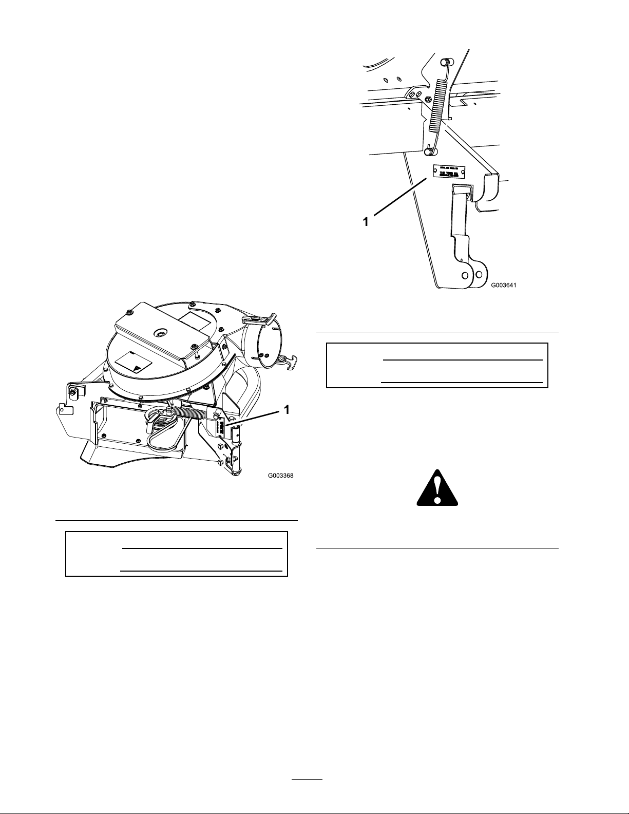
and serial n umbers of y our product ready . Figure 1
identifies the location of the model and serial n umbers
on the product. W rite the n umbers in the space
pro vided.
Figure 2
1. Bagger model and serial number location
Model No.
Serial No.
Figure 1
1. Blower model and serial number location
Model No.
Serial No.
T his man ual identifies potential hazards and has
safety messag es identified b y the safety aler t symbol
( Figure 3 ), whic h signals a hazard that ma y cause
serious injur y or death if y ou do not follo w the
recommended precautions .
Figure 3
1. Safety alert symbol
T his man ual uses 2 other w ords to highlight
infor mation. Impor tant calls attention to special
mec hanical infor mation and Note emphasizes g eneral
infor mation w or th y of special attention.
Contents
Introduction . . . . . . . . . . . . . . . . . . . . . . . . . . . . . . . . . . . . . . . . . . . . . . . . . . . . . . . . . 2
Safety . . . . . . . . . . . . . . . . . . . . . . . . . . . . . . . . . . . . . . . . . . . . . . . . . . . . . . . . . . . . . . . . . . 4
Safety and Instr uctional Decals . . . . . . . . . . . . . . . . . . . . . . . . 4
Setup . . . . . . . . . . . . . . . . . . . . . . . . . . . . . . . . . . . . . . . . . . . . . . . . . . . . . . . . . . . . . . . . . . . 6
1 Pre paring the Mo w er . . . . . . . . . . . . . . . . . . . . . . . . . . . . . . . . . . . . 7
2 Installing the Bag g er Mounting Brac k et . . . . . . . . . . . 7
3 Tightening all Mounting Bolts . . . . . . . . . . . . . . . . . . . . . . . . 9
© 2006—The Toro® Company
8111 Lyndale Avenue South
Bloomington, MN 55420
Contact us at www.Toro.com.
2
Printed in the USA.
All Rights Reserved
Page 3

4 Installing the Hood Assembly and
Bags . . . . . . . . . . . . . . . . . . . . . . . . . . . . . . . . . . . . . . . . . . . . . . . 9
5 R outing the Bag g er Belt into the Blo w er
Assembly . . . . . . . . . . . . . . . . . . . . . . . . . . . . . . . . . . . . . . 11
6 Installing the Blo w er Assembly . . . . . . . . . . . . . . . . . . . . 11
7 Installing the Disc harg e T ubes . . . . . . . . . . . . . . . . . . . . . 13
8 Installing the Belt Co v er . . . . . . . . . . . . . . . . . . . . . . . . . . . . . . 16
9 Installing the W eights . . . . . . . . . . . . . . . . . . . . . . . . . . . . . . . . . 16
10 Adjusting the P arking Brak e . . . . . . . . . . . . . . . . . . . . . . . 17
11 Chec king the Tire Pressure . . . . . . . . . . . . . . . . . . . . . . . . 17
Operation . . . . . . . . . . . . . . . . . . . . . . . . . . . . . . . . . . . . . . . . . . . . . . . . . . . . . . . . . . 19
P ositioning the Adjustable Baffle . . . . . . . . . . . . . . . . . . . . 19
Emptying the Grass Bags . . . . . . . . . . . . . . . . . . . . . . . . . . . . . . . 20
Clearing Obstr uctions from the Bag g er
System . . . . . . . . . . . . . . . . . . . . . . . . . . . . . . . . . . . . . . . . . 20
R emo ving the Bag g er . . . . . . . . . . . . . . . . . . . . . . . . . . . . . . . . . . . . 21
Using the Grass Deflector . . . . . . . . . . . . . . . . . . . . . . . . . . . . . . 21
T ranspor ting Mac hines . . . . . . . . . . . . . . . . . . . . . . . . . . . . . . . . . . 21
Operating Tips . . . . . . . . . . . . . . . . . . . . . . . . . . . . . . . . . . . . . . . . . . . . 21
Maintenance . . . . . . . . . . . . . . . . . . . . . . . . . . . . . . . . . . . . . . . . . . . . . . . . . . . . . . . 24
R ecommended Maintenance
Sc hedule(s) . . . . . . . . . . . . . . . . . . . . . . . . . . . . . . . . . . . 24
Cleaning the Hood Screen . . . . . . . . . . . . . . . . . . . . . . . . . . . . . 24
Cleaning the Bag g er and Bags . . . . . . . . . . . . . . . . . . . . . . . . . 24
Inspecting the Bag g er Belt . . . . . . . . . . . . . . . . . . . . . . . . . . . . . 24
R e placing the Bag g er Belt . . . . . . . . . . . . . . . . . . . . . . . . . . . . . . 24
Chec king and Adjusting the Blo w er
Latc h . . . . . . . . . . . . . . . . . . . . . . . . . . . . . . . . . . . . . . . . . . . 25
Greasing the Idler Ar m . . . . . . . . . . . . . . . . . . . . . . . . . . . . . . . . . 25
Inspecting the Bag g er . . . . . . . . . . . . . . . . . . . . . . . . . . . . . . . . . . . 25
Inspecting the Mo w er Blades . . . . . . . . . . . . . . . . . . . . . . . . . 26
Installing the Mo w er Blades . . . . . . . . . . . . . . . . . . . . . . . . . . . 26
Installing the Grass Deflector . . . . . . . . . . . . . . . . . . . . . . . . . 26
Storag e . . . . . . . . . . . . . . . . . . . . . . . . . . . . . . . . . . . . . . . . . . . . . . . . . . . . . . . . . . . . . . 27
T roubleshooting . . . . . . . . . . . . . . . . . . . . . . . . . . . . . . . . . . . . . . . . . . . . . . . . . 28
3
Page 4
Safety
T he follo wing list contains safety infor mation
specific to T oro products and other safety
infor mation y ou m ust kno w .
• Become familiar with the safe operation of the
equipment, with the operator controls , and
safety signs .
• Use extra care with g rass catc hers or other
attac hments . T hese can c hang e the operating
c haracteristics and the stability of the mac hine .
• F ollo w the man ufacturer’ s recommendations
for adding or remo ving wheel w eights or
counterw eights to impro v e stability .
• Do not use a g rass catc her on stee p slopes . A
hea vy g rass catc her could cause loss of control
or o v er tur n the mac hine .
• Slo w do wn and use extra care on hillsides . Be
sure to tra v el in the recommended direction
on hillsides . T urf conditions can affect the
mac hine’ s stability . Use extreme caution while
operating near drop-offs .
• K ee p all mo v ement on slopes slo w and
g radual. Do not mak e sudden c hang es in
speed, directions or tur ning .
• T he g rass catc her can obstr uct the view to the
rear . Use extra care when operating in rev erse .
• Use care when loading or unloading the
mac hine into a trailer or tr uc k
• Nev er operate with the disc harg e deflector
raised, remo v ed or altered, unless using a g rass
catc her .
• K ee p hands and feet a w a y from mo ving par ts .
Do not mak e adjustments with the engine
r unning .
• Stop on lev el g round, diseng ag e dri v es , c hoc k
or bloc k wheels , shut off engine before lea ving
the operator’ s position for any reason including
emptying the g rass catc her or unclog ging the
c hute .
• If y ou remo v e the g rass catc her , be sure to
install any disc harg e deflector or guard that
might ha v e been remo v ed to install the g rass
catc her . Do not operate the mo w er without
either the entire g rass catc her or the g rass
deflector in place .
• Stop the engine before remo ving the g rass
catc her or unclog ging the c hute .
• Do not lea v e g rass in g rass catc her for
extended periods of time .
• Grass catc her components are subject to w ear ,
damag e and deterioration, whic h could expose
mo ving par ts or allo w objects to be thro wn.
F requently c hec k components and re place
with man ufacturer’ s recommended par ts , when
necessar y .
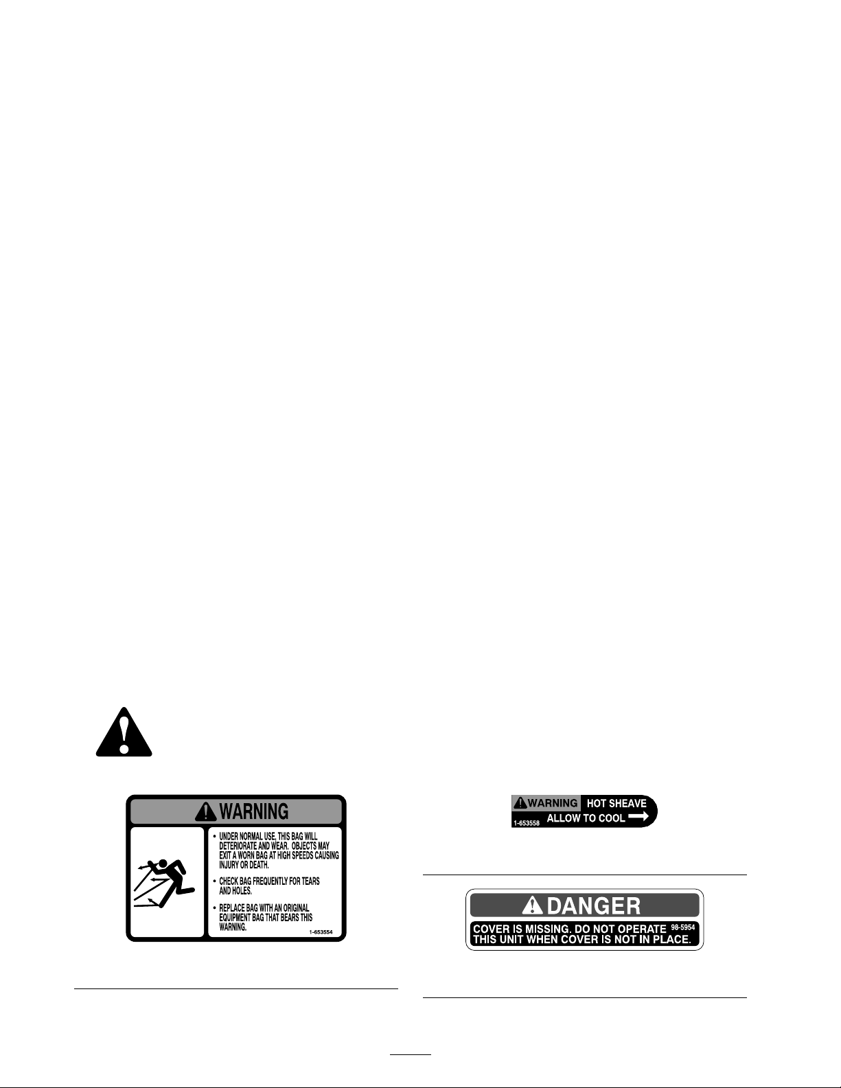
Safety and Instructional
Decals
Safety decals and instr uctions are easily visible to the operator and are located near any
area of potential dang er . R e place any decal that is damag ed or lost.
1-653558
1-653554
4
98-5954
Page 5

103-3507
106-3339
5
Page 6

Setup
Loose Parts
Use the chart below to verify that all parts have been shipped.
Step
1
2
3
4
5
6
7
8
9
No parts required
Bagger mounting bracket
Bagger side plate
Spacer 2
Bolt, (3/8 x 1-1/2 inches)
Bolt, (3/8 x 1 inch) (for Z593
mowers only)
Flange Nut, (3/8 inch)
Curved washer
No parts required
Hood assembly
Bags
Clevis pin
Hairpin cotter pin
Bagger belt (from Blower and Drive
Kit)
Blower assembly (from Blower and
Drive Kit)
Spring (from Blower and Drive Kit)
Upper tube
Lower tube
Bolt, (#10 x 3/4 inches)
Locknut, (#10)
Washer, (7/32 inch)
Belt cover (from Blower and Drive
Kit)
Caster weight
U-bolt
Nut, (1/2 inch)
Lock washer, (1/2 inch)
Plate
Description
Qty.
–
1
2
14
2
14
14
–
1
3
2
2
1
1
1
1
1
3
3
3
2
2
4
4
2
Prepare the mower.
Install the bagger mounting bracket
Tighten all mounting bolts
Install the hood assembly and bags.
Route the bagger belt into the
blower assembly.
Install the blower assembly.
Install the discharge tubes.
Install the belt cover.
Install the weights.
Use
10
11
No parts required
No parts required
–
–
Adjust the parking brake.
Check the tire pressure.
Note: Deter mine the left and right sides of the mac hine from the nor mal operating position.
6
Page 7

Step
1
Preparing the Mower
No Parts Required
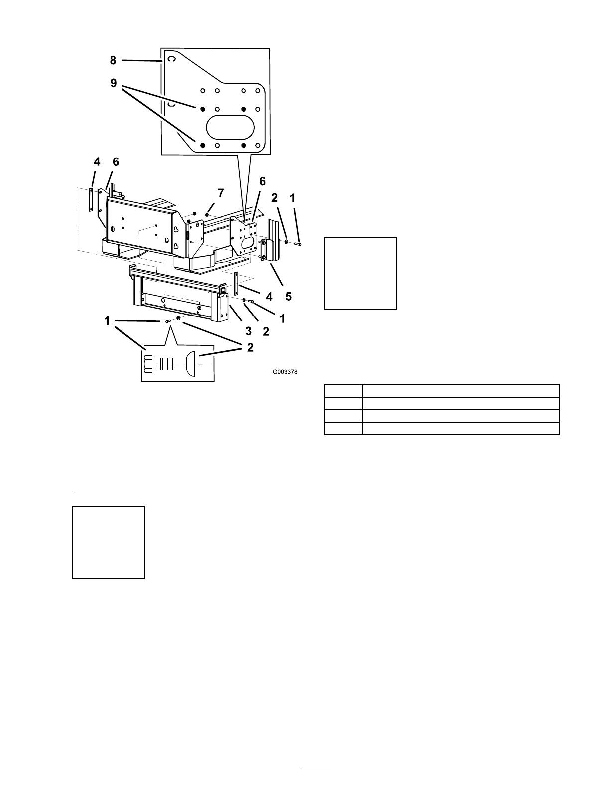
1. R emo v e the bolts , n uts , and w ashers holding
the roll bar to one side of the mac hine . Discard
the n uts , bolts , and w ashers ( Figure 4 , Figure 5 ,
and Figure 6 ).
2. Install the bag g er side plate and the roll bar
section to the side of the mac hine using 4 bolts
(3/8 x 1-1/2 inc hes), 4 cur v ed w ashers (3/8
inc h), and 4 flang e n uts (3/8 inc h) ( Figure 4 ,
Figure 5 , and Figure 6 ).
Procedure
P erfor m the follo wing procedure to pre pare the
mo w er for attac hing the blo w er and finishing kit.
1. Diseng ag e the PTO , mo v e the motion control
lev ers to the neutral loc k ed position and set
the parking brak e .
2. Stop the engine , remo v e the k ey , and w ait for
all mo ving par ts to stop before lea ving the
operating position.
3. R e pair all bent or damag ed areas of mo w er
dec k and re place any missing par ts .
4. Clean the mo w er of any debris on the dec k or
rear par t of the mo w er to ease installation.
Step
2
3. R e peat the ste ps abo v e for the opposite side
( Figure 4 , Figure 5 , and Figure 6 ).
Note: Mak e sure the cur v ed w ashers are
installed as sho wn in Figure 4 , Figure 5 , and
Figure 6 .
4. Install the bag g er mounting brac k et to the left
and right bag g er side brac k ets with 4 bolts
(3/8 x 1-1/2 inc hes), 4 cur v ed w ashers (3/8
inc h), and 4 flang e n uts (3/8 inc h) ( Figure 4 ,
Figure 5 , and Figure 6 ).
5. Install the bag g er mounting brac k et to the
rear frame of the mac hine with 2 bolts (3/8 x
1-1/2 inc hes) (use 2 bolts (3/8 x 1 inc h) for
Z593 mo w ers as sho wn in Figure 5 ), 2 cur v ed
w ashers (3/8 inc h), and 2 flang e n uts (3/8
inc h) ( Figure 4 , Figure 5 , and Figure 6 ).
Installing the Bagger
Mounting Bracket
Parts needed for this step:
1
Bagger mounting bracket
2
Bagger side plate
2 Spacer
14
Bolt, (3/8 x 1-1/2 inches)
2
Bolt, (3/8 x 1 inch) (for Z593 mowers only)
14
Flange Nut, (3/8 inch)
14
Curved washer
Procedure
Important: Do not tighten an y bolts until
both side brack ets and ba g ger mounting
brack et ar e fit loose on the machine.
R efer to Tightening the Mounting Bolts f or
the cor r ect pr ocedur e to tighten the bolts.
7
Page 8
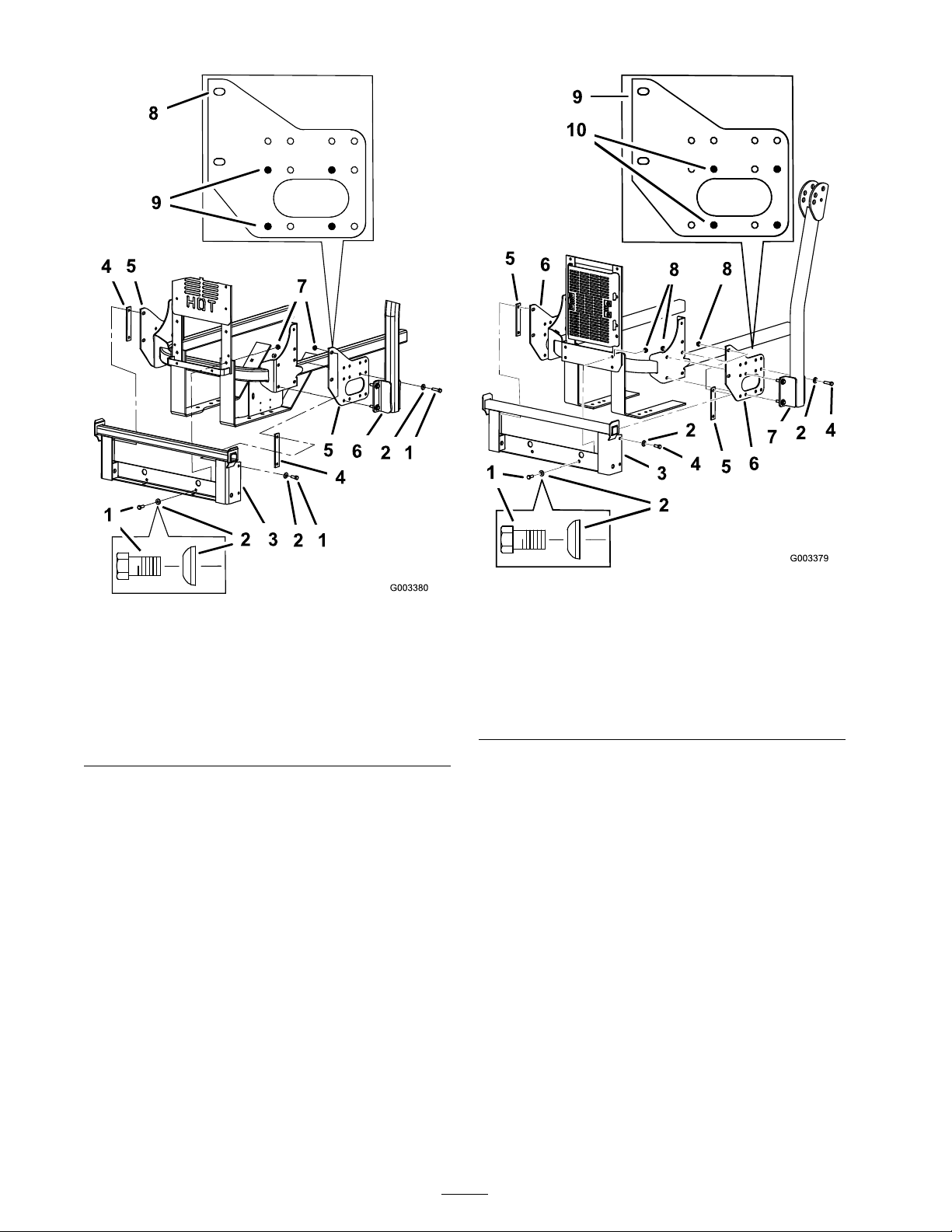
Figure 5
Figure 4
For Z500 Gas Mowers
1. Bolt, (3/8 x 1-1/2 inches)
2. Curved washer, (3/8 inch) 7. Flange nut, (3/8 inch)
3. Bagger mounting bracket 8. Side view of bagger side
4. Spacer if needed 9. Holes to use when
5. Bagger side plate
6. ROPS
plate
installing the side bracket
For Z593 Diesel Mowers
1. Bolt, (3/8 x 1 inch)
2. Curved washer, (3/8 inch)
3. Bagger mounting bracket
4. Bolt, (3/8 x 1-1/2 inches)
5. Spacer if needed 10. Holes to use when
6. Bagger side plate
7. ROPS
8. Flange nut, (3/8 inch)
9. Side view of bagger side
plate
installing the side bracket
8
Page 9
1. Tighten the bag g er mounting brac k et to the
rear frame first.
2. Tighten the R OPS and side brac k ets to the side
of the mo w er .
3. If there is a g ap betw een the bag g er mounting
brac k et and the side brac k ets of an 1/8 inc h
or more , install one or both of the spacers
betw een the bag g er mounting brac k et and
mounting plates ( Figure 4 , Figure 5 , and
Figure 6 ).
4. Tighten the bag g er mounting brac k et to the
side brac k ets .
Step
4
Installing the Hood
Assembly and Bags
Figure 6
For Z597 Diesel Mowers
1. Bolt, (3/8 x 1-1/2 inches)
2. Curved washer, (3/8 inch) 7. Flange nut, (3/8 inch)
3. Bagger mounting bracket 8. Side view of bagger side
4. Spacer if needed 9. Holes to use when
5. Bagger side plate
6. ROPS
plate
installing the side bracket
Step
3
Tightening all Mounting
Bolts
No Parts Required
Parts needed for this step:
1
Hood assembly
Bags
3
2
Clevis pin
2
Hairpin cotter pin
Procedure
1. Install the hood assembly onto the bag g er
mounting brac k et ( Figure 7 ).
Procedure
T he follo wing ste ps are the cor rect sequence to
tighten the side brac k ets and the bag g er mounting
brac k et. All mounting bolts need to be tor qued to
35 ft-lb (48 N ⋅ m).
9
Page 10
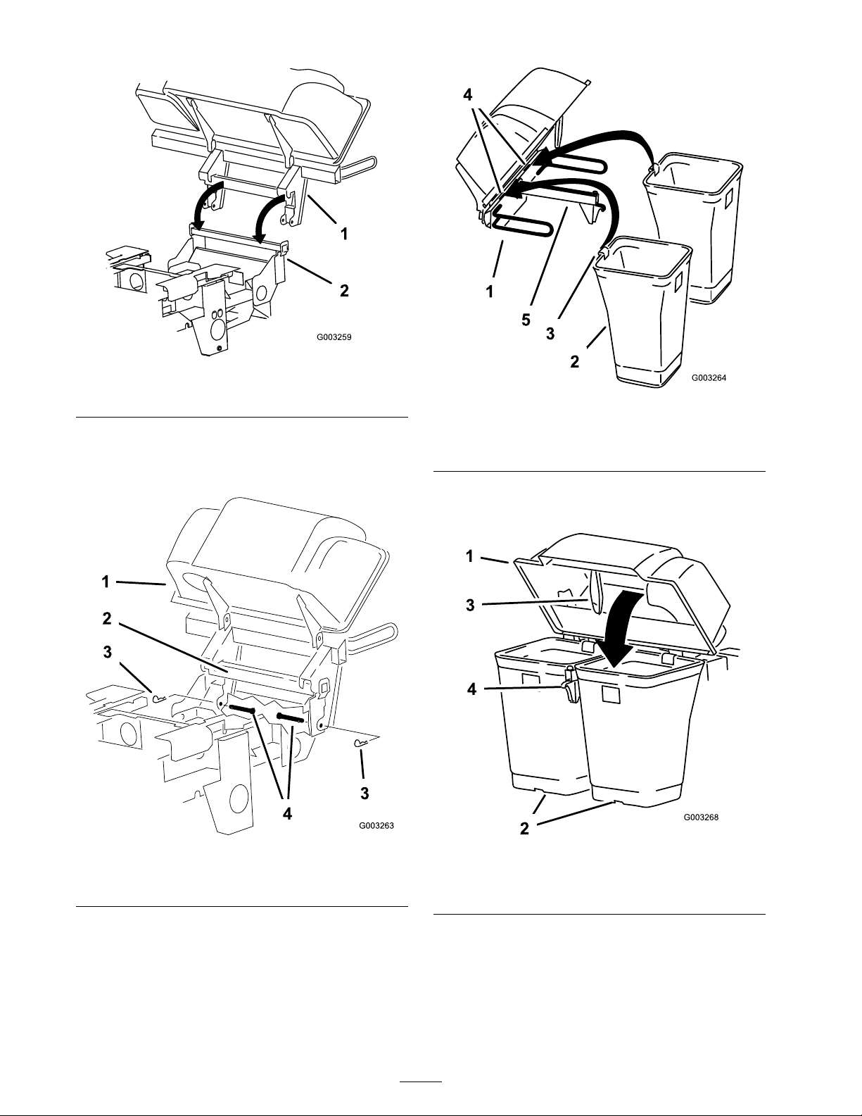
Figure 7
1. Hood assembly 2. Bagger mounting bracket
2. Install the 2 clevis pins into the hood assembly
and bag g er mounting brac k et. Secure them
with 2 hair pin cotter pins ( Figure 8 ).
Figure 9
1. Hood assembly 4. Notch
2. Bag
3. Bag tab
5. Bagger frame
4. Lo w er the bag g er hood o v er the bags
( Figure 10 ).
Figure 8
1. Hood assembly
2. Bagger mounting bracket 4. Clevis pin
3. Hairpin cotter pin
3. Install the bag tab into the notc h in the hood
assembly . Do this for all bags ( Figure 9 ).
Note: T he bags will rest on the bag g er frame .
Figure 10
1. Hood 3. Bagger latch
2. Bag
4. Latch hook
5. P osition the bag g er latc h under the latc h hook
( Figure 11 ).
6. Push do wn on bag g er latc h until it loc ks into
place ( Figure 11 ).
10
Page 11

Figure 11
1. Bagger latch 2. Latch hook
Step
5
Routing the Bagger Belt
Figure 12
1. Idler pulley 5. Belt
2. Mower deck pulley 6. Belt guide bolt
3. Spring
4. Peg
7. Fixed idler pulley
8. Blower pulley
Step
into the Blower Assembly
Parts needed for this step:
1
Bagger belt (from Blower and Drive Kit)
Procedure
1. Loosen the belt guide bolt ( Figure 12 ).
2. Install the belt around the blo w er pulley
( Figure 12 ).
3. Install the belt betw een the fix ed idler pulley
and the belt guide bolt.
4. Tighten the belt guide bolt ( Figure 12 ).
5. Install the belt onto the spring loaded idler
pulley ( Figure 12 ).
6
Installing the Blower
Assembly
Parts needed for this step:
1
Blower assembly (from Blower and Drive Kit)
1
Spring (from Blower and Drive Kit)
Procedure
An unco v er ed discharge opening could
allo w the la wn mo w er to thr o w objects in
the operator’ s or bystander’ s dir ection and
r esult in serious injur y . Also, contact with
the blade could occur .
• Nev er operate the la wn mo w er unless
y ou install a co v er plate, a mulch plate, or
a g rass chute and catcher .
• Mak e sur e the g rass deflector is installed
when the g rass chute and catcher ar e
r emo v ed.
11
Page 12

1. R emo v e the side disc harg e c hute from the
mo w er dec k ( Figure 13 ).
Figure 13
1. Bolt 5. Spring installed
2. Spacer
3. Locknut 7. L end of spring, place
4. Spring
6. Grass Deector
behind deck edge before
installing bolt
8. J hook end of spring
assembly ag ainst the mo w er dec k , but can be
released b y hand ( Figure 15 ).
Figure 15
1. Latch 3. Blower assembly
2. Bolt
4. Install the spring as sho wn in Figure 16 .
2. Slide the blo w er assembly peg into the pi v ot
hole ( Figure 14 ).
Figure 14
1. Blower assembly 3. Pivot hole
2. Mower deck 4. Blower assembly peg
Figure 16
1. Spring loaded idler pulley 3. Long hook end
2. Short hook end
5. Pull the spring loaded idler pulley bac k and
route the belt around the mo w er dec k pulley .
Ensure the belt is routed around the blo w er
pulleys cor rectly ( Figure 17 ).
3. Close the blo w er assembly to see if the latc hes
are adjusted cor rectly . Loosen or tighten the
bolt so the latc hes fir mly hold the blo w er
12
Page 13

Figure 17
1. Mower deck pulley 3. Blower
2. Spring loaded Idler pulley
Step
7
5. Install the upper tube into the bag g er opening
and pull it bac k out so the r ubber seal is
protr uding out ( Figure 18 ).
Figure 18
1. Upper tube 3. Bagger hood
2. Bagger opening
6. With the hood in the do wn position and
latc hed, measure the distance the tube is inside
the hood.
Installing the Discharge
Tubes
Parts needed for this step:
1
Upper tube
1
Lower tube
3
Bolt, (#10 x 3/4 inches)
3
Locknut, (#10)
3
Washer, (7/32 inch)
Procedure
Important: Mak e sur e the mo w er deck
is in the lo w est height-of-cut position while
installing the discharge tubes.
Note: R emember to re place the g rass deflector
when the bag g er is remo v ed from the mo w er .
R efer to R e placing the Grass Deflector .
1. Diseng ag e the PTO and set the parking brak e .
2. Stop the engine , remo v e the k ey , and w ait for
all mo ving par ts to stop before lea ving the
operating position.
3. Lo w er the mo w er dec k to the lo w est
height-of-cut position.
4. R emo v e the bags from the hood assembly .
Measure from the hood plate to the edg e of
the tube as sho wn in Figure 19 . T his distance
needs to be 3/4 inc h (19 mm).
Figure 19
1. Hood plate
2. Upper tube 5. Edge of tube
3. Hood in the down position
4. 3/4 inch (19 mm)
7. Once the 3/4 inc h (19 mm) measurement has
been ac hiev ed, mark the upper tube on the
13
Page 14

out side where the r ubber seal protr udes out.
T his is mark ed to ensure the cor rect position
for the upper tube when drilling the holes
and connecting the upper and lo w er tubes
( Figure 20 ).
Note: T he r ubber seal m ust protr ude out
from the bag g er hood.
Figure 21
1. Lower tube 2. Upper tube
9. Slide the lo w er tube onto the boot and latc h
them tog ether ( Figure 22 ).
Figure 20
1. Upper tube 3. Bagger hood
2. Rubber seal protruding out 4. Mark here against the
rubber seal
8. Install the lo w er tube into the upper tube
( Figure 21 ).
Note: T here is a latc h on the top and bottom
of the blo w er housing .
14
Page 15

Figure 22
1. Blower assembly 3. Latch
2. Lower tube
Figure 23
1. Bagger hood 4. Upper tube
2. Mark against the rubber
seal
3. Drill 7/32 inch diameter
holes here (use upper tube
as a template)
5. Lower tube
6. Blower assembly
10. Mak e sure the mo w er dec k is in the lo w est
height-of-cut position.
11. Chec k to mak e sure the mark from Figure 20
is still in place .
12. Using the three holes in the upper tube as a
template , drill three holes (7/32 inc h diameter)
where the upper and lo w er tubes join tog ether
( Figure 23 ).
13. R emo v e the lo w er tube from the blo w er .
14. J oin the upper and lo w er tubes with 3 bolts
(#10 x 3/4 inc hes), 3 flat w ashers (7/32 inc h),
and 3 loc kn uts (#10) ( Figure 24 ).
15
Page 16

1. Lower tube
2. Upper tube
3. Flat washer, (7/32 inch)
Figure 24
4. Locknut, (#10)
5. Bolt, (#10 x 3/4 inches)
Figure 25
1. Belt cover 5. Latch
2. Blower assembly 6. Belt cover notch
3. Pulley assembly 7. Belt cover support
4. Belt cover bracket
15. Install the lo w er tube onto the blo w er housing
and secure it with the latc hes .
16. Install the bags onto the bag g er .
Step
8
Installing the Belt Cover
Parts needed for this step:
Belt cover (from Blower and Drive Kit)
Procedure
1. Lo w er the mo w er dec k to the lo w est
height-of-cut position.
2. Install the new belt co v er so the notc hes on
both sides g o o v er the belt co v er suppor ts and
secure the latc h ( Figure 25 ).
Step
9
Installing the Weights
Parts needed for this step:
2
Caster weight
2
U-bolt
4
Nut, (1/2 inch)
4
Lock washer, (1/2 inch)
2
Plate
Procedure
T o comply with ANSI/OPEI
B71.4-2004 Standard, front w eights m ust
be added to the mac hine .
T he ba g ger adds a lot of w eight to the r ear
of the machine and may cause an unsta ble
condition which could r esult in a loss of
contr ol.
16
Page 17

1. Place caster w eights on the front casters .
2. Install plate , n uts (1/2 inc h) and loc k w asher
(1/2 inc h) under the frame and w eight
( Figure 26 ).
3. R e peat for opposite side .
Note: All Z Master mo w ers recei v e the caster
w eights .
Figure 26
1. Front caster weight
2. U-bolt
3. Plate 6. Lock washer
4. Nut
5. Front caster
Figure 27
1. Brake lever
2. Spring (2-3/4 inches/70
mm)
3. Adjusting nuts 7. Trunnion roller
4. Collar on brake rod
3. If adjustment is necessar y , loosen the jam n ut
belo w the spring and tighten the n ut directly
belo w the y ok e ( Figure 27 ). T ur n the n ut until
the cor rect measurement is obtained. Tighten
the tw o n uts tog ether and re peat on opposite
side of unit.
4. T ur n n uts cloc kwise to shor ten spring length
and tur n counter -cloc kwise to lengthen the
spring .
5. 3/16–1/4 inch (5–7 mm)
6. Jam nut and yoke
Step
10
Adjusting the Parking Brake
No Parts Required
Procedure
Chec k the parking brak e for proper adjustment.
1. Diseng ag e brak e lev er (lev er do wn).
2. Measure the length of the spring .
T he measurement should be 2-3/4 inc h (70
mm) betw een w ashers ( Figure 27 ).
5. Eng ag e parking brak e , lev er up .
6. Measure the distance betw een the tr unnion
roller and the collar on brak e rod.
T he measurement should be 3/16-1/4 inc h
(5-7 mm) ( Figure 27 ).
7. If adjustment is necessar y , loosen the jam n ut
directly belo w the y ok e . T ur n the bottom rod
until the cor rect measurement is obtained
( Figure 27 ). Tighten jam n ut at y ok e
Step
11
Checking the Tire Pressure
No Parts Required
Procedure
Note: Increase the tire pressure due to the
additional w eight.
17
Page 18

Chec k and increase the air pressure in the front
caster wheels and rear tires ( Figure 28 ).
Pressure: R ear tires-20 psi (90 kP a)
F ront caster wheels-25 psi (90 kP a)
Figure 28
18
Page 19

Operation
Note: Deter mine the left and right sides of the
mac hine from the nor mal operating position.
Important: Set the par king brak e when
lea ving the machine unattended, ev en if just
f or a few min utes.
T o a v oid per sonal injur y , f ollo w these
pr ocedur es:
• Become f amiliar with all operating and
safety instr uctions in the operator’ s
man ual f or y our mo w er bef or e using this
attachment.
• Nev er r emo v e the ba g ger or ba g ger tubes
while the engine is r unning .
• Al w ays shut the engine of f and w ait f or
all mo ving par ts to stop bef or e clearing
an obstr uction fr om the ba g ging system.
• Nev er do maintenance or r epair s while
the engine is r unning .
• Set the par king brak e.
W ithout the g rass deflector , ba g ger tubes
or complete ba g ger assembl y mounted in
place, y ou and other s ar e exposed to blade
contact and thr o wn de bris. Contact with the
r otating mo w er blade(s) and thr o wn de bris
will cause injur y or death.
• Al w ays install the g rass deflector when
r emo ving the ba g ger and changing to
side discharge mode.
• If the g rass deflector is ev er dama ged,
r eplace it immediatel y . T he g rass
deflector r outes material do wn to w ard
the turf.
• Nev er put y our hands or feet under the
mo w er .
• Nev er tr y to clear the discharge ar ea or
mo w er blades unless y ou mo v e the po w er
tak e of f (PT O) to of f and r otate the
ignition k ey to of f. Also r emo v e the k ey
and pull the wir e of f of the spar k plug(s).
• T ur n of f the engine bef or e unclo g ging
the discharge chute.
Childr en or bystander s may be injur ed if
they mo v e or attempt to operate the tractor
while it is unattended.
Al w ays r emo v e the ignition k ey and set the
par king brak e when lea ving the machine
unattended, ev en if just f or a few min utes.
Positioning the Adjustable
Bafe
Adjust the baffle to position B (middle position)
for bag ging . R efer to the mac hines Operator
Man ual for the baffle adjustment procedure .
19
Page 20

Figure 29
Emptying the Grass Bags
Figure 30
1. Bag
2. Bottom handle
Grass bags are hea vy when full. Be careful when
lifting or handling a g rass bag that is full.
1. Diseng ag e the PTO , set the parking brak e , and
c hoc k or bloc k the tires if on a slope .
2. Unlatc h the bag g er latc h.
3. Open the bag g er hood.
4. Compress the debris into the bags . With both
hands , lift up on the bag and unhook it from
the bag g er brac k et.
5. Grab the handle on the bottom of the bag and
tip it o v er to empty the bag ( Figure 30 ).
6. R e peat for the other bag .
7. Install the bag tab into the notc h in the bag g er
suppor t frame . Do this for both bags .
8. Lo w er the bag g er hood o v er the bags .
9. Latc h the bag g er hood.
Clearing Obstructions from
the Bagger System
W hen the ba g ger is in operation, the blo w er
can be r otating and cut of f or injur e hands.
• Bef or e adjusting , cleaning , r epairing
and inspecting the blo w er , and bef or e
unclo g ging the chute, tur n of f the engine
and w ait f or all mo ving par ts to stop .
R emo v e the k ey .
• Use a stick, not y our hands, to r emo v e an
obstr uction fr om the blo w er and tube.
• K eep f ace, hands, feet, and an y other
par t of y our body or clothing a w ay fr om
concealed, mo ving , or r otating par ts.
1. Diseng ag e the PTO and set the parking brak e .
2. T ur n off the engine , remo v e the k ey , and w ait
for all mo ving par ts to stop before lea ving the
operating position.
3. Empty the bags .
20
Page 21

4. Unlatc h the lo w er tube .
5. R emo v e the tubes from the bag g er .
6. Using a stic k or similar object, not y our hands ,
to remo v e and clear the obstr uction from the
tube assembly .
Note: In most cases , the debris can be shak en
out of the tubes .
10. If y ou are c hanging to side disc harg e mode ,
ensure the g rass deflector is installed and can
be lo w ered into w orking position.
11. R emo v e the hood and bag assembly .
Using the Grass Deector
7. If the blo w er assembly is plug g ed, unlatc h the
bag g er blo w er assembly , remo v e the belt, and
swing it open.
8. Using a stic k or similar object, not y our hands ,
to remo v e and clear the obstr uction from the
blo w er assembly .
9. After y ou remo v e the obstr uction, install the
complete bag g er system and resume operation.
Removing the Bagger
Components ar ound engine will be hot if the
machine has been r unning . T ouching hot
components can cause bur ns.
• Do not touch engine components when
hot.
• Allo w engine to cool bef or e r emo ving the
ba g ger .
W ithout the g rass deflector , discharge
co v er , or complete g rass catcher assembl y
mounted in place, y ou and other s ar e
exposed to blade contact and thr o wn de bris.
Contact with r otating mo w er blade(s) and
thr o wn de bris will cause injur y or death.
• Al w ays install the g rass deflector when
r emo ving the ba g ger and changing to
side discharge mode.
• If the g rass deflector is ev er dama ged,
r eplace it immediatel y . T he g rass
deflector r outes material do wn to w ard
the turf.
• Nev er put y our hands or feet under the
mo w er .
• Nev er tr y to clear the discharge ar ea or
mo w er blades unless y ou mo v e the po w er
tak e of f (PT O) to the of f position, r otate
the ignition k ey to of f and r emo v e the
k ey .
1. Diseng ag e the PTO , set the parking brak e , and
c hoc k or bloc k the tires .
2. T ur n off the engine , remo v e the k ey , and w ait
for all mo ving par ts to stop before lea ving the
operating position.
3. Unlatc h the lo w er tube from the blo w er and
remo v e the tube from the blo w er assembly .
4. R emo v e the tube from the bag g er hood.
5. Lo w er the mo w er dec k to the lo w est
height-of-cut position.
6. Unlatc h the belt co v er o v er the mo w er pulley
assembly .
7. R emo v e the bag g er belt from the mo w er pulley
assembly .
8. Open the blo w er assembly .
9. R emo v e the blo w er assembly from the pi v ot
hole .
Transporting Machines
Do not lea v e g rass or debris in the bag g er while
transpor ting the mac hine .
T ranspor ting the machine with g rass
or de bris in the ba g ger can dama ge the
machine.
Do not lea v e g rass or de bris in the ba g ger
while transpor ting the machine.
Operating Tips
Machine Size
R emember that the mac hine is long er and wider
with this attac hment installed. By tur ning too
21
Page 22

shar ply in confined places y ou ma y damag e the
attac hment or other proper ty .
Trimming
Alw a ys trim with the left side of the mo w er . Do
not trim with the right side of the mo w er because
y ou could damag e the bag ging tubes .
Cutting Height
F or optim um bag ging perfor mance , set the dec k
height-of-cut to remo v e no more that 2 to 3 inc hes
(51 to 76 mm) or 1/3 of the g rass height, whic h
ev er is less . Cutting off more than this will reduce
the capacity of the v acuum system.
Bagging Long Grass
If the g rass is ev er allo w ed to g ro w long er than
nor mal, or if it contains a high deg ree of moisture ,
raise the cutting height higher than usual and cut
and bag the g rass at this setting . T hen cut and bag
the g rass ag ain using the lo w er , nor mal setting .
Ex cessi v ely long g rass is hea vy and ma y not be
propelled completely into the bag g er . If this
happens , the tube and blo w er ma y plug . T o a v oid
plug ging the bag ging system, mo w the g rass at
a high height-of-cut, then lo w er the mo w er to
y our nor mal cutting height and re peat the bag ging
process .
Bagging Wet Grass
Cutting Frequency
Cut the g rass often, especially when it g ro ws
rapidly . Y ou will ha v e to cut y our g rass twice if
it g ets ex cessi v ely long (refer to Bag ging Long
Grass).
Cutting Technique
F or best la wn appearance , be sure to slightly
o v erlap the mo w er into the previously cut area.
T his helps reduce the load on the engine and
reduces the c hance of plug ging the blo w er
assembly and tubes .
Bagging Speed
T he bag ging system ma y plug if y ou dri v e too fast
and the engine speed g ets too slo w . On hills it ma y
be necessar y to slo w the mac hines g round speed.
Mo w do wn hill whenev er possible .
As the ba g ger fills, extra w eight is added to
the back of the machine. If y ou stop and
star t suddenl y on hills, y ou may lose steering
contr ol or the machine may tip .
• Do not star t or stop suddenl y when going
uphill or do wnhill. A v oid uphill star ts.
• If y ou do stop the machine when going
uphill, disenga ge the PT O . T hen back
do wn the hill using a slo w speed.
• Do not change speeds or stop on slopes.
If possible , alw a ys tr y to cut g rass when it is dr y .
W et g rass can cause plug ging .
Reducing Plugging
T o a v oid plug ging the bag ging system, reduce
g round speed and mo w the g rass at a high
height-of-cut, then lo w er the mo w er to y our
nor mal cutting height and re peat the bag ging
process .
Signs of Plugging
As y ou are bag ging, a small amount of g rass
clippings nor mally blo w out the front of the
mo w er . An ex cessi v e amount of clipping blo w-out
indicates that the bag g er is full or the tube is
plug g ed.
Bagging Blades
In most mo wing conditions , the standard high lift
blades will pro vide the best bag ging perfor mance .
T he T oro Atomic blade is recommended for
bag ging lea v es in dr y conditions . In dr y dusty
conditions , the medium lift or lo w lift blades will
reduce dust and dir t blo w out while pro viding
effecti v e bag ging air flo w .
Contact an A uthorized Ser vice Dealer for the
proper blades for different mo wing conditions .
Curb Climbing and Loading
Alw a ys lift the dec k to the highest position
when loading the mac hine on trailers or
ascending/descending a curb . Lea ving the mo w er
in a lo w er position can cause damag e to the mo w er
22
Page 23

while loading and g oing o v er a curb . If a curb is
higher than 6 inc hes (152 mm), cross it at a shar p
angle with the dec k fully raised. Use extreme
caution when loading onto a trailer .
23
Page 24

Maintenance
Recommended Maintenance Schedule(s)
Maintenance Service
Interval
After the rst 8 operating
hours
Before each use or daily
Every 25 hours
Every 50 hours
Every 100 hours
Maintenance Procedure
• Inspect the bagger belt.
• Inspect the bagger.
• Clean the hood screen.
• Clean the bagger.
• Inspect the bagger belt.
• Grease the idler arm.
• Inspect the bagger.
Cleaning the Hood Screen
T he screens need to be cleaned before eac h use . In
w et g rass they will need to be cleaned more often.
1. Diseng ag e the po w er tak e off (PTO) and set
the parking brak e .
2. T ur n off the engine , remo v e the k ey , and w ait
for all mo ving par ts to stop before lea ving the
operating position.
3. Open the bag g er hood.
4. Clean the debris from the screen.
5. Close the bag g er hood.
Replacing the Bagger Belt
1. Diseng ag e the PTO , mo v e the motion control
lev ers to the neutral loc k ed position, and set
the parking brak e .
2. Stop the engine , remo v e the k ey , and w ait for
all mo ving par ts to stop before lea ving the
operating position.
3. Loosen the belt guide bolt ( Figure 12 ).
4. R emo v e the existing bag g er belt.
5. Install the new belt around the blo w er pulley
( Figure 12 ).
Cleaning the Bagger and
Bags
T he bag g er needs to be cleaned daily .
1. W ash the inside and outside of the bag g er
hood, bags , tube , and the underside of the
mo w er . Use a mild automoti v e deterg ent to
remo v e dir t.
2. Mak e sure y ou remo v e matted g rass from all
par ts .
3. After w ashing all par ts , let them dr y thoroughly .
Note: With all par ts installed, star t and r un the
mac hine for a min ute to assist in dr ying .
Inspecting the Bagger Belt
T he bag g er belt tension needs to be c hec k ed after
the first 8 hours and ev er y 25 hours there after .
Chec k belts for crac ks , fra yed edg es , bur n marks
or any other damag e . R e place damag ed belts .
6. Install the belt betw een the fix ed idler pulley
and the belt guide bolt.
7. Tighten the belt guide bolt ( Figure 12 ).
24
Page 25

Figure 31
1. Idler pulley 5. Belt
2. Mower deck pulley 6. Belt guide bolt
3. Spring
4. Peg
7. Fixed idler pulley
8. Blower pulley
8. Install the spring as sho wn in Figure 32 .
Figure 33
1. Latch 3. Blower assembly
2. Bolt
Greasing the Idler Arm
Grease the bag g er belt idler ar m ( Figure 34 ) ev er y
50 hours .
Figure 32
1. Spring loaded idler pulley 3. Long hook end
2. Short hook end
9. Install the belt onto the spring loaded idler
pulley ( Figure 12 ).
Checking and Adjusting the
Blower Latch
Close the blo w er assembly to see if the latc hes are
adjusted cor rectly . Loosen or tighten the bolt so
the latc hes fir mly hold the blo w er assembly ag ainst
the mo w er dec k , but can be released b y hand.
Figure 34
Inspecting the Bagger
Inspect the bag g er attac hment after the first 8
hours of operation, and 100 hours thereafter .
1. Diseng ag e the PTO , mo v e the motion control
lev ers to the neutral loc k ed position, and set
the parking brak e .
2. Stop the engine , remo v e the k ey , and w ait for
all mo ving par ts to stop before lea ving the
operating position.
25
Page 26

3. Chec k the upper tube , lo w er tube , bag g er
hood, and the blo w er assembly . R e place these
par ts if they are crac k ed or brok en.
4. Chec k the bags , bag g er frame , and screen.
R e place any par ts that are crac k ed or brok en.
5. Tighten all n uts bolts and screws .
Inspecting the Mower Blades
1. Inspect the mo w er blades regularly and
whenev er a blade strik es a foreign object.
2. If blades are badly w or n or damag ed, install
new blades . R efer to y our mo w er Operator’ s
Manual for complete blade maintenance .
Installing the Mower Blades
In most mo wing conditions , the standard high lift
blades will pro vide the best bag ging perfor mance .
T he T oro Atomic blade is recommended for
bag ging lea v es in dr y conditions . In dr y dusty
conditions , the medium lift or lo w lift blades will
reduce dust and dir t blo w out while pro viding
effecti v e bag ging air flo w .
2. R emo v e the damag ed or w or n g rass deflector .
3. Place the spacer and spring onto the g rass
deflector . Place the L end of the spring behind
the dec k edg e .
Note: Mak e sure the L end of the spring is
installed behind the dec k edg e before installing
the bolt as sho wn in Figure 35
4. Install the bolt and n ut.
5. Place the J hook end of the spring around the
g rass deflector ( Figure 35 ).
Important: T he g rass deflector must be
a ble to lo w er do wn into position. Lift the
deflector up to test that it lo w er s into the
full do wn position.
Contact an A uthorized Ser vice Dealer for the
proper blades for different mo wing conditions .
R efer to the mo w er Operator’ s Manual for more
infor mation on installing blades .
Installing the Grass
Deector
An unco v er ed discharge opening could
allo w the la wn mo w er to thr o w objects in
the operator’ s or bystander’ s dir ection and
r esult in serious injur y . Also, contact with
the blade could occur .
• Nev er operate the la wn mo w er unless
y ou install a co v er plate, a mulch plate, or
a g rass chute and catcher .
• Mak e sur e the g rass deflector is in the
do wn position.
Figure 35
1. Bolt 5. Spring installed
2. Spacer
3. Locknut 7. L end of spring, place
4. Spring
6. Grass Deector
behind deck edge before
installing bolt
8. J hook end of spring
1. R emo v e the loc kn ut, bolt, spring and spacer
holding the deflector to the pi v ot brac k ets
( Figure 35 ).
26
Page 27

Storage
1. Clean the bag g er attac hment. R efer to Cleaning
the Bag g er .
2. Inspect the bag g er attac hment for damag e .
R efer to Inspecting the Bag g er .
3. Mak e sure the bags are empty and thoroughly
dr y .
4. Chec k the belt for w ear or crac ks .
5. Store the mac hine in a clean, dr y place , out of
direct sunlight. If y ou m ust store the mac hine
outside , co v er it with a w eather proof co v er .
T his protects the plastic par ts and extends the
life of the mac hine .
27
Page 28

Troubleshooting
Problem
Abnormal vibration.
Reduced bagging
performance.
1. Cutting blade(s) is/are
2. Blade mounting bolt is
3. Loose blower pulley or
4. Worn bagger belt. 4. Replace belt.
5. Blower fan blade(s) is/are
1. Low engine speed. 1. Always operate the
2. Plugged screen in bagger
3. Loose bagger belt. 3. Replace the bagger belt.
4. A plugged tube or
5. Full bags. 5. Empty the hopper.
Possible Cause Corrective Action
1. Install new cutting
bent or unbalanced.
2. Tighten the blade
loose.
3. Tighten the appropriate
pulley assembly.
5. Contact an Authorized
bent or unbalanced.
2. Remove debris, leaves or
hood.
4. Locate and remove
blower.
blade(s).
mounting bolt.
pulley.
Service Dealer.
bagger at full throttle.
grass clippings from the
screen.
plugged debris.
Blower and tubes plug too
frequently.
Debris blowout.
1. Bags are too full. 1. Dump more frequently.
2. Low engine speed. 2. Always operate the
bagger at full throttle.
3. Grass is too wet.
4. Grass is too long. 4. Cut no more than 2-3
5. Plugged screen in bagger
hood.
6. Ground speed is too fast. 6. Drive slower at full
7. Worn bagger belt. 7. Replace belt.
1. Bags are too full. 1. Dump more frequently.
2. Ground speed is too fast. 2. Drive slower at full
3. Mower deck is not
leveled.
3. Cut grass when it is dry.
inches (51-76 mm) or
1/3 of the grass height,
which ever is less.
5. Remove debris, leaves or
grass clippings from the
screen.
throttle.
throttle.
3. See the mower
operator’s manual for
leveling the mower deck.
28
Page 29

Problem
Possible Cause Corrective Action
Blower impeller does not
spin freely.
1. Plugged blower. 1. Remove debris, leaves or
grass clippings from the
blower impeller.
2. Impeller not aligned. 2. Contact an Authorized
Service Dealer.
29
Page 30

Page 31

Page 32

Landscape Contractor
Equipment (LCE)
The Toro Total Coverage Guarantee
A Limited Warranty
Conditions and Products Covered
The Toro Company and its affiliate, Toro Warranty Company,
pursuant to an agreement between them, jointly promise to repair
the listed Toro product if defective in materials or workmanship.
This warranty applies to:
• ProLine Mid-Size Walk Power Mowers and Accessories
• Z Master Mid-Mount ZRTs and Accessories
The following time periods apply from the date of purchase:
Components
• Engines* 2 years
• Hydraulic Systems 2 years
• Traction Unit Frame 2 years
• Carrier Frame 2 years
• Deck Shells 2 years
• Deck Spindles 3 years Parts, 2 years Labor
• Z500 Series Clutches 2 years
• Remaining Components 1 year
This warranty includes the cost of parts and labor, but you must
pay transportation costs.
* Some engines used on Toro LCE products are warranted by the
engine manufacturer.
Warranty Period
Instructions for Obtaining Warranty Service
If you think that your Toro LCE product contains a defect in
materials or workmanship, follow this procedure:
1. Contact any Toro Authorized or Master Service Dealer to
arrange service at their dealership. To locate a dealer
convenient to you, access our website at www.Toro.com. You
may also call our Toro Customer Care Department toll free at
888-865–5676 (U.S. customers) or 888-865–5691 (Canada
customers).
2. Bring the product and your proof of purchase (sales receipt) to
the Service Dealer.
If for any reason you are dissatisfied with the Service Dealer’s
analysis or with the assistance provided, call us toll free at the
numbers above or write us at:
LCE Customer Care Department
8111 Lyndale Avenue South
Bloomington, MN 55420-1196
You must maintain your Toro product by following the maintenance
procedures described in the Operator’s Manual. Such routine
maintenance, whether performed by a dealer or by you, is at your
expense.
There is no other express warranty except for special emission
system coverage on some products. This express warranty does
not cover the following:
• Cost of regular maintenance service or parts, such as filters,
fuel, lubricants, tune-up parts, blade sharpening, brake and
clutch adjustments.
• Any product or part which has been altered or misused or
required replacement or repair due to normal wear, accidents,
or lack of proper maintenance.
• Repairs necessary due to improper fuel, contaminants in the
fuel system, or failure to properly prepare the fuel system prior
to any period of non-use over three months.
• Pickup and delivery charges.
• Operational misuse, neglect, or accidents.
• Repairs or attempted repairs by anyone other than an
Authorized Toro Service Dealer using Toro approved parts.
All repairs covered by this warranty must be performed by an
Authorized Toro Service Dealer using Toro approved replacement
parts.
Repair by an Authorized Toro Service Dealer is your sole
remedy under this warranty.
Neither The Toro Company nor Toro Warranty Company is
liable for indirect, incidental or consequential damages in
connection with the use of the Toro products covered by this
warranty, including any cost or expense of providing substitute equipment or service during reasonable periods of
malfunction or non-use pending completion of repairs under
this warranty.
Some states do not allow exclusions of incidental or
consequential damages, or limitations on how long an
implied warranty lasts, so the above exclusions and
limitations may not apply to you.
All implied warranties of merchantability (that the product is
fit for ordinary use) and fitness for use (that the product is fit
for a particular purpose) are limited to the duration of the
express warranty.
This warranty gives you specific legal rights, and you may
also have other rights which vary from state to state.
Owner Responsibilities
Items and Conditions Not Covered
General Conditions
Countries Other than the United States or Canada
Customers who have purchased Toro products exported from the United States or Canada should contact their Toro Distributor (Dealer)
to obtain guarantee policies for your country, province, or state. If for any reason you are dissatisfied with your Distributor’s service or
have difficulty obtaining guarantee information, contact the Toro importer. If all other remedies fail, you may contact us at Toro Warranty
Company.
Part No. 374-0037 Rev. E
 Loading...