

Page 1
FormNo.3395-267RevA
48inor52inE-ZVac
Z400SeriesZMaster
ModelNo.78531—SerialNo.315000001andUp
ModelNo.78532—SerialNo.315000001andUp
®
Mowers
™
Bagger
Registeratwww.T oro.com.
OriginalInstructions(EN)
*3395-267*A
Page 2
ThisproductcomplieswithallrelevantEuropeandirectives.
Fordetails,pleaseseetheDeclarationofIncorporation(DOI)
atthebackofthispublication.
Introduction
Readthisinformationcarefullytolearnhowtooperateand
maintainyourproductproperlyandtoavoidinjuryand
productdamage.Youareresponsibleforoperatingthe
productproperlyandsafely.
YoumaycontactTorodirectlyatwww .Toro.comforproduct
safetyandoperationtrainingmaterials,accessoryinformation,
helpndingadealer,ortoregisteryourproduct.
Wheneveryouneedservice,genuineT oroparts,oradditional
information,contactanAuthorizedServiceDealerorToro
CustomerServiceandhavethemodelandserialnumbersof
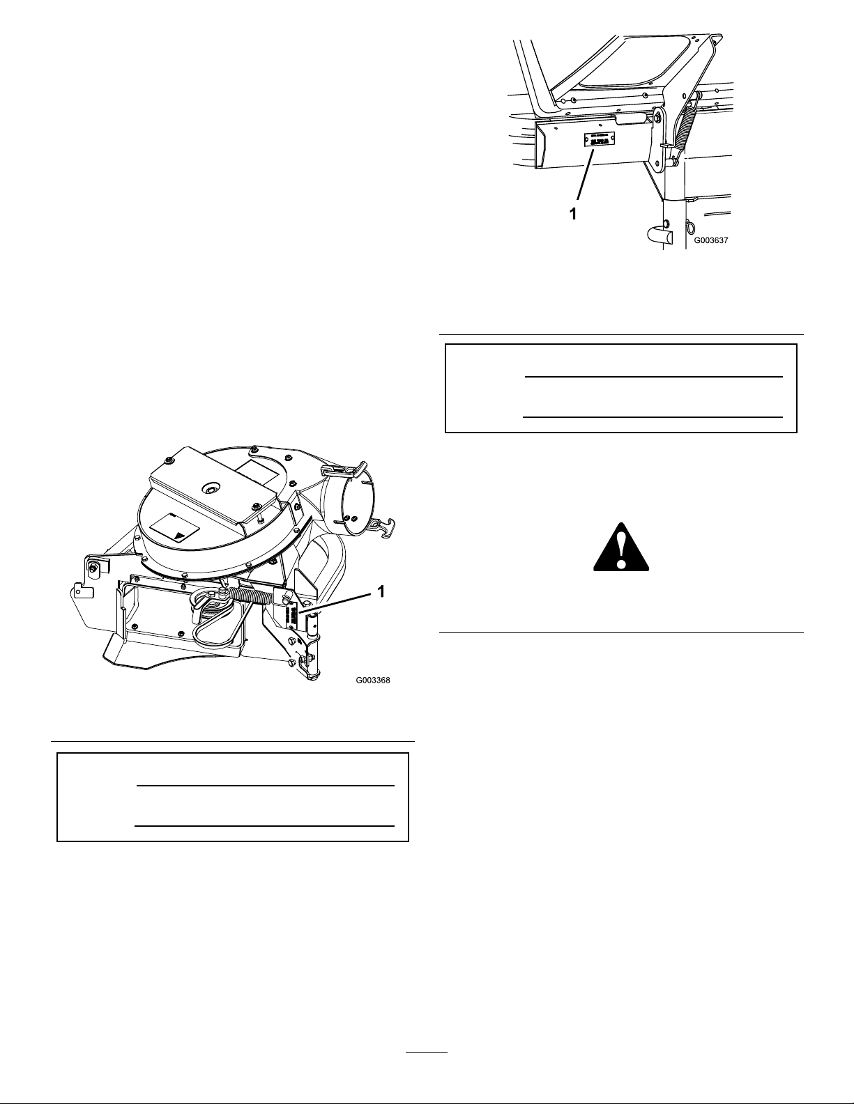
yourproductready.Figure1identiesthelocationofthe
modelandserialnumbersontheproduct.Writethenumbers
inthespaceprovided.
Figure2
BaggerSerialNumber
1.Baggermodelandserialnumberlocation
ModelNo.
SerialNo.
Figure1
1.Blowermodelandserialnumberlocation
ModelNo.
SerialNo.
Thismanualidentiespotentialhazardsandhassafety
messagesidentiedbythesafetyalertsymbol(Figure3),
whichsignalsahazardthatmaycauseseriousinjuryordeath
ifyoudonotfollowtherecommendedprecautions.
Figure3
1.Safetyalertsymbol
Thismanualuses2wordstohighlightinformation.
Importantcallsattentiontospecialmechanicalinformation
andNoteemphasizesgeneralinformationworthyofspecial
attention.
Contents
Safety...........................................................................3
SafetyandInstructionalDecals.................................4
Setup............................................................................5
1PreparingtheMachine...........................................6
2InstallingtheBaggerBracket(Z400Mowerswith
48-inchMowerDecks).........................................6
3InstallingtheBaggerBracket(Z400Mowerswith
52-inchMowerDecks).........................................7
4InstallingtheHoodAssemblyandBags....................8
5RoutingtheBaggerBeltintotheBlower
Assembly...........................................................10
6InstallingtheBlowerAssembly..............................10
7AdjustingtheFlowBafe......................................12
8InstallingtheDischargeTubes...............................13
©2015—TheToro®Company
8111LyndaleAvenueSouth
Bloomington,MN55420
Contactusatwww.Toro.com.
2
PrintedintheUSA
AllRightsReserved
Page 3

9InstallingtheBeltCover........................................16
10InstallingtheWeightfora48-inchBagger...............16
11InstallingtheWeightsfora52-inch
Bagger...............................................................16
12AdjustingtheParkingBrake.................................17
13CheckingtheTirePressure..................................18
Operation....................................................................18
PositioningtheAdjustableBafe..............................19
EmptyingtheGrassBags.........................................19
ClearingObstructionsfromtheBagger
System..............................................................19
RemovingtheBagger..............................................20
UsingtheGrassDeector.......................................20
TransportingtheMachine........................................20
OperatingTips......................................................20
Maintenance.................................................................22
RecommendedMaintenanceSchedule(s)......................22
CleaningtheHoodScreen.......................................22
CleaningtheBaggerandBags...................................22
InspectingtheBaggerBelt.......................................22
ReplacingtheBaggerBelt........................................22
CheckingandAdjustingtheBlowerLatch..................23
GreasingtheIdlerArm...........................................23
InspectingtheBagger.............................................23
InspectingtheMowerBlades...................................23
InstallingtheMowerBlades.....................................24
InstallingtheGrassDeector...................................24
Storage........................................................................25
Troubleshooting...........................................................26
Safety
ThefollowinglistcontainssafetyinformationspecictoToro
productsandothersafetyinformationyoumustknow .
•Becomefamiliarwiththesafeoperationoftheequipment,
withtheoperatorcontrols,andsafetysigns.
•Useextracarewithgrasscatchersorotherattachments.
Thesecanchangetheoperatingcharacteristicsandthe
stabilityofthemachine.
•Followthemanufacturer'srecommendationsforadding
orremovingwheelweightsorcounterweightstoimprove
stability.
•Donotuseagrasscatcheronsteepslopes.Aheavy
grasscatchercouldcauselossofcontroloroverturnthe
machine.
•Slowdownanduseextracareonhillsides.Besureto
travelintherecommendeddirectiononhillsides.Turf
conditionscanaffectthemachine'sstability.Useextreme
cautionwhileoperatingneardrop-offs.
•Keepallmovementonslopesslowandgradual.Donot
makesuddenchangesinspeed,directionsorturning.
•Thegrasscatchercanobstructtheviewtotherear.Use
extracarewhenoperatinginreverse.
•Usecarewhenloadingorunloadingthemachineintoa
trailerortruck.
•Neveroperatewiththedischargedeectorraised,
removedoraltered,unlessusingagrasscatcher.
•Keephandsandfeetawayfrommovingparts.Donot
makeadjustmentswiththeenginerunning.
•Stoponlevelground,disengagedrives,chockorblock
wheels,shutoffenginebeforeleavingtheoperator's
positionforanyreasonincludingemptyingthegrass
catcheroruncloggingthechute.
•Ifyouremovethegrasscatcher,besuretoinstallany
dischargedeectororguardthatmighthavebeen
removedtoinstallthegrasscatcher.Donotoperatethe
machinewithouteithertheentiregrasscatcherorthe
grassdeectorinplace.
•Stoptheenginebeforeremovingthegrasscatcheror
uncloggingthechute.
•Donotleavegrassingrasscatcherforextendedperiods
oftime.
•Grasscatchercomponentsaresubjecttowear,damage
anddeterioration,whichcouldexposemovingpartsor
allowobjectstobethrown.Frequentlycheckcomponents
andreplacewithmanufacturer'srecommendedparts,
whennecessary.
3
Page 4
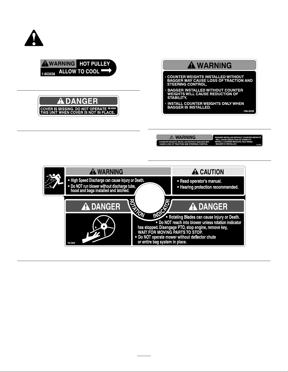
SafetyandInstructionalDecals
Safetydecalsandinstructionsareeasilyvisibletotheoperatorandarelocatednearanyareaofpotential
danger.Replaceanydecalthatisdamagedorlost.
1-653558
98-5954
103-3508
106-3339
112-2318
4
Page 5

Setup
LooseParts
Usethechartbelowtoverifythatallpartshavebeenshipped.
ProcedureDescription
1
2
3
4
5
6
7
8
Nopartsrequired
Baggerbracket1
Bolt(5/16x1inch)
Flangenut(5/16inch)
Baggerbracket1
Bolt(5/16x1inch)
Flangenut(5/16inch)
Hoodassembly1
Bags2
Clevispin
Hairpincotter2
Baggerbelt(fromBlowerandDriveKit)
Blowerassembly(fromBlowerand
DriveKit)
Spring(fromBlowerandDriveKit)
Nopartsrequired
Uppertube1
Lowertube1
Bolt(#10x3/4inches)
Locknut(#10)
Washer(7/32inch)
Qty.
Use
–
8
8
8
8
2
1
1
1
–
3
3
3
Preparethemachine.
Installthebaggerbracket(Z400Mowers
with48-inchmowerdecks).
Installthebaggerbracket(AllZ400
Mowerswith52-inchmowerdecks).
Installthehoodassemblyandbags.
Routethebaggerbeltintotheblower
assembly.
Installtheblowerassembly .
Adjusttheowbafe.
Installthedischargetubes.
9
10
11
12
13
Note:Determinetheleftandrightsidesofthemachinefromthenormaloperatingposition.
Nopartsrequired
Weight1
Bolt(3/8x2inches)
Locknut(3/8inch)
Washer(3/8inch)
Weight2
Bolt(3/8x3inches)
Locknut(3/8inch)
Washer(3/8inch)
Nopartsrequired
Nopartsrequired
–
2
2
4
2
2
4
–
–
Installthebeltcover.
Installtheweightfora48-inchbagger.
Installtheweightsfora52-inchbagger.
Adjusttheparkingbrake.
Checkthetirepressure.
5
Page 6
1
PreparingtheMachine
NoPartsRequired
Procedure
Performthefollowingproceduretopreparethemachinefor
attachingtheblowerandnishingkit.
1.DisengagethePTO ,movethemotioncontrolleversto
theneutrallockedpositionandsettheparkingbrake.
2.Stoptheengine,removethekey,andwaitforallmoving
partstostopbeforeleavingtheoperatingposition.
3.Repairallbentordamagedareasofmowerdeckand
replaceanymissingparts.
4.Cleanthemachineofanydebrisonthedeckorrear
partofthemachinetoeaseinstallation.
2
InstallingtheBaggerBracket (Z400Mowerswith48-inch MowerDecks)
Partsneededforthisprocedure:
1Baggerbracket
8
Bolt(5/16x1inch)
8
Flangenut(5/16inch)
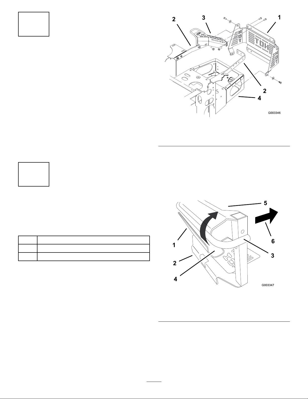
Figure4
1.Heatshield3.Tailpipeguard
2.Enginestraps4.Rearbumper
Note:Note:Installtheheatshieldintothebagger
bracketfromthefrontofthebracket.
3.Insertthetopoftheheatshield(atanangle)underthe
barofthebaggerbracket(Figure5).
Note:Positionthebaggerbarasfaraspossibleinto
theheatshieldnotches.
Procedure
1.Removethe8boltsandnutssecuringtherearof
theheatshieldtotheenginestrapsandrearbumper
(Figure4).
Note:Discardtheboltsandnuts.
2.Removethe4bolts,washersandnutssecuringthe
sidesoftheheatshieldtotheenginestraps,tailpipe
guardandbumper.Retaintheheatshieldandthese
bolts,washers,andnuts(Figure4).
Figure5
1.Heatshield4.Heatshieldnotch
2.Baggerbracket
3.Bar
4.Withthebaggerbarintheheatshieldnotches,push
thebottomoftheheatshieldtowardtherearandpast
thebackofthebaggerbracket(Figure6).
6
5.Frontofthebaggerbracket
6.Frontofthemachine
Page 7
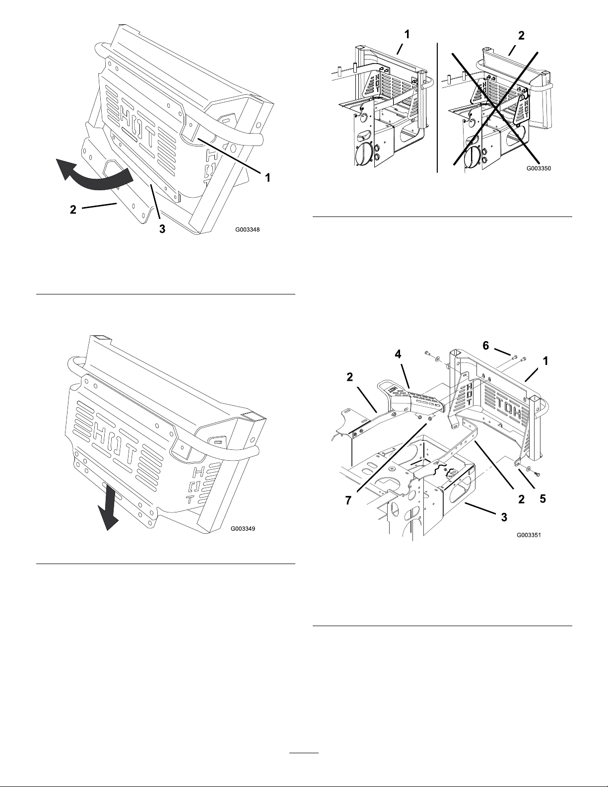
Figure8
Figure6
1.Heatshieldnotch
2.Backofbagger
3.Bottomofheatshield
5.Slidetheheatshielddownuntiltheholesalignwiththe
bagger-bracketholes(Figure7).
1.Correctposition
2.Incorrectposition
6.Installthebaggerbracketandheatshieldtotherearof
theenginestrapsandrearbumperwith8newbolts
(5/16x1inch)and8newangenuts(5/16inch)as
showninFigure9.
7.Installthebaggerbracketandheatshieldtotheside
oftheenginestraps,tailpipeguardandrearbumper
with4bolts,4washersand4angenuts,previously
removed(Figure9).
Figure7
Note:Makesuretoinstallthebaggerbracketcorrectly,
asshowninFigure8.
1.Baggerbracket5.Heatshield
2.Enginestraps
3.Rearbumper
4.Tailpipeguard
7
Figure9
6.Bolt(5/16x1inch)
7.Nut(5/16inch)
Page 8
3
InstallingtheBaggerBracket
(Z400Mowerswith52-inch
MowerDecks)
Partsneededforthisprocedure:
1Baggerbracket
8
Bolt(5/16x1inch)
8
Flangenut(5/16inch)
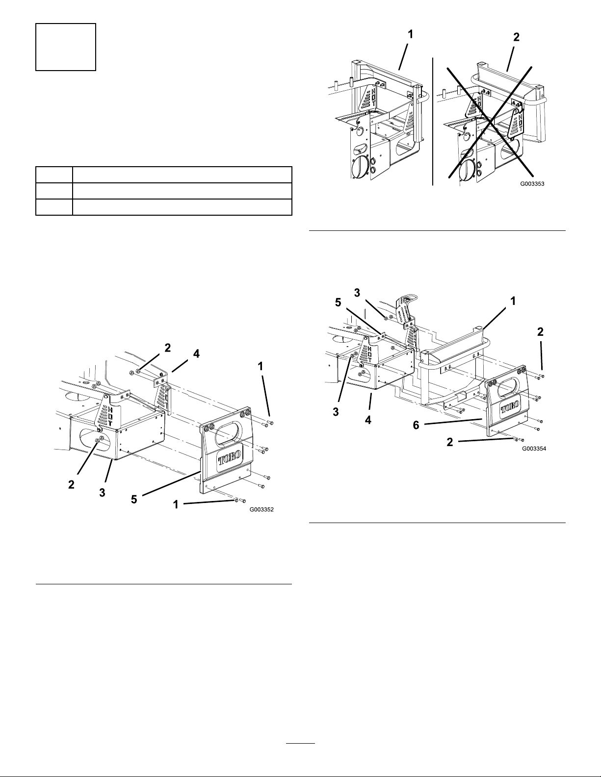
1.Correctposition
Figure11
2.Incorrectposition
Procedure
Note:Usetheseinstructionsifmachineisequippedwith
arearweight.
1.Removetherearweightfromthebackofthemachine
(Figure10).
Note:Savetheboltsandangenuts.
Figure10
2.Installthebaggerbracketandweighttotheengine
straps,tailpipeguard,andrearbumperwiththe8
existingboltsandnutspreviouslyremoved(Figure12).
Figure12
1.Baggerbracket4.Rearbumper
2.Bolt5.Engine-guardstrap
3.Flangenut6.Rearweight
1.Bolt4.Engine-guardstrap
2.Flangenut5.Rearweight
3.Rearbumper
Note:Makesuretoinstallthebaggerbracketcorrectly,
asshowninFigure11.
8
Page 9

4
InstallingtheHoodAssembly
andBags
Partsneededforthisprocedure:
1Hoodassembly
2Bags
2
Clevispin
2Hairpincotter
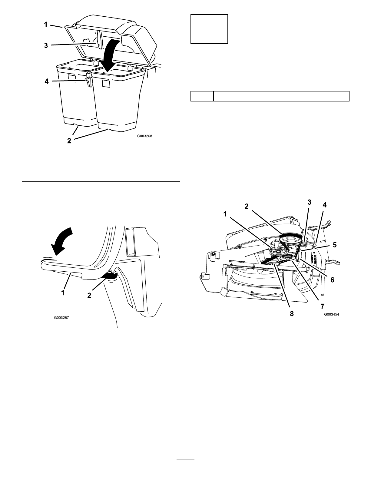
Figure14
1.Hoodassembly3.Hairpincotter
2.Bagger-mountingbracket
4.Clevispin
Procedure
1.Installthehoodassemblyintothebagger-mounting
bracket(Figure13).
3.Installthebagtabintothenotchinthehoodassembly
(Figure15).
Note:Dothisforallbags.Thebagsrestonthe
baggerframe.
Figure13
1.Bagger-mountingbracket2.Hoodassembly
2.Installthe2clevispinsintothehoodassemblyand
bagger-mountingbracket.Secureitwith2hairpin
cotters(Figure14).
Figure15
1.Hoodassembly4.Notch
2.Bag
3.Bagtab
4.Lowerthebaggerhoodoverthebags(Figure16).
9
5.Baggerframe
Page 10
5
RoutingtheBaggerBeltinto theBlowerAssembly
Partsneededforthisprocedure:
1
Baggerbelt(fromBlowerandDriveKit)
Procedure
1.Loosenthebelt-guidebolt(Figure18).
2.Installthebeltaroundtheblowerpulley(Figure18).
Figure16
1.Hood3.Baggerlatch
2.Bag4.Latchhook
5.Positionthebaggerlatchunderthelatchhook(Figure
17).
6.Pushdownonbaggerlatchuntilitlocksintoplace
(Figure17).
Figure17
1.Baggerlatch2.Latchhook
3.Installthebeltbetweenthexedidlerpulleyandthe
belt-guidebolt.
4.Installthebeltontothespring-loadedidlerpulley
(Figure18).
5.Tightenthebelt-guidebolt(Figure18).
Figure18
1.Idlerpulley5.Belt
2.Mower-deckpulley6.Belt-guidebolt
3.Spring
4.Peg8.Blowerpulley
7.Fixedidlerpulley
10
Page 11

6
InstallingtheBlowerAssembly
Partsneededforthisprocedure:
1
Blowerassembly(fromBlowerandDriveKit)
1
Spring(fromBlowerandDriveKit)
Procedure
WARNING
Anuncovereddischargeopeningcouldallowthe
machinetothrowobjectsintheoperator'sor
bystander'sdirectionandresultinseriousinjury.
Also,contactwiththebladecouldoccur.
•Neveroperatethemachineunlessyouinstalla
coverplate,amulchplate,oragrasschuteand
catcher.
•Makesurethatthegrassdeectorisinstalled
whenyouremovethegrasschute.
Figure20
48-inchMowerDeck
1.Blowerassembly3.Pivothole
2.Mowerdeck4.Blower-assemblypeg
1.Removethesidedischargechutefromthemowerdeck.
Figure19
1.Bolt
2.Spacer6.Grassdeector
3.Locknut
4.Spring8.J-hookendofspring
5.Springinstalled
7.L-endofspring,place
behinddeckedgebefore
installingbolt
3.Closetheblowerassemblytoseeifthelatchisadjusted
correctly.Loosenortightentheboltsothelatchrmly
holdstheblowerassemblyagainstthemowerdeck,but
canbereleasedbyhand(Figure21).
Figure21
1.Latch3.Blowerassembly
2.Bolt
4.InstallthespringasshowninFigure22.
2.Slidetheblowerassemblypegintothepivothole
(Figure20).
11
Page 12

7
AdjustingtheFlowBafe
NoPartsRequired
Procedure
1.Swingtheleveruptoloosenthecamlock(Figure24).
2.Aligntheowbafeandcamlockintheslottothe
edgeoftheblowerassembly.
Figure22
1.Spring-loadedidlerpulley
2.Short-hookend
5.Pullthespring-loadedidlerpulleybackandroutethe
beltaroundthemowerdeckpulley(Figure23).
Note:Ensurethebeltisroutedaroundtheblower
pulleyscorrectly
3.Long-hookend
3.Swingtheleverbackovertotightenthebafeandcam
lock(Figure24).
4.Ifthecamdoesnotlockthebafeintoplaceoritis
tootight,loosentheleverandthenrotatethecamlock.
Note:Adjustthecamlockuntilyouachievethe
desiredlockingpressure.
Figure24
Figure23
1.Mowerdeckpulley3.Blowerassembly
2.Spring-loadedidlerpulley
1.Camlock
2.Lever
12
3.Rotatecamtoincreaseor
decreaselockingpressure
4.Slot
Page 13

8
InstallingtheDischargeTubes
Partsneededforthisprocedure:
1Uppertube
1Lowertube
3
Bolt(#10x3/4inches)
3
Locknut(#10)
3
Washer(7/32inch)
Procedure
Important:Makesurethatthemowerdeckisinthe
lowestheight-of-cutpositionwhenyouinstallthe
dischargetubes.
Note:Measurefromthehoodplatetotheedgeof
thetubeasshowninFigure26.Thisdistanceneeds
tobe19mm(3/4inch).
Note:Remembertoreplacethegrassdeectorwhenyou
removethebaggerfromthemachine.RefertoInstallingthe
GrassDeector(page24).
1.DisengagethePTOandsettheparkingbrake.
2.Stoptheengine,removethekey,andwaitforallmoving
partstostopbeforeleavingtheoperatingposition.
3.Lowerthemowerdecktothelowestheight-of-cut
position.
4.Removethebagsfromthehoodassembly.
5.Installtheuppertubeintothebaggeropeningandpull
itbackoutsothattherubbersealisprotrudingout
(Figure25).
Figure26
1.Hoodplate
2.Uppertube
3.Hoodinthedownposition
withtherightbagremoved
7.Onceyouachievethe19mm(3/4inch)measurement,
marktheuppertubeontheoutsideatthepointwhere
therubbersealprotrudesout(Figure27).
Note:Thisismarkedtoensurethecorrectposition
fortheuppertubewhendrillingtheholesand
connectingtheupperandlowertubes.Therubberseal
mustprotrudeoutfromthebaggerhood.
4.19mm(3/4inch)
5.Edgeoftube
Figure25
1.Uppertube3.Baggerhood
2.Baggeropening
6.Withthehoodinthedownpositionandtheright-hand
bagremoved,measurethedistancethetubeisinside
thehood.
Figure27
1.Uppertube3.Baggerhood
2.Rubbersealprotrudingout4.Markhere
13
Page 14

8.Installthelowertubeintotheuppertube(Figure28).
Figure28
1.Lowertube2.Uppertube
9.Slidethelowertubeontothebootandlatchthem
together(Figure29).
Note:Thereisalatchonthetopandbottomofthe
blowerhousing.
Figure29
1.Blowerassembly3.Latch
2.Lowertube
10.Makesurethatthemowerdeckisinthelowest
height-of-cutpositionandthemarkontheuppertube
isstillpositionedagainsttheprotrudingrubberseal..
11.Usingthe3holesintheuppertubeasatemplate,drill3
holes(7/32inchdiameter)wheretheupperandlower
tubesjointogether(Figure30).
14
Page 15

Figure30
1.Baggerhood4.Uppertube
2.Markatrubberseal5.Lowertube
3.Drill7/32inchdiameter
holeshere(useuppertube
asatemplate)
6.Blowerassembly
12.Removethelowertubefromtheblower.
13.Jointheupperandlowertubeswith3bolts(#10x
3/4inches),3atwashers(7/32inch),and3locknuts
(#10)asshowninFigure31.
Figure31
1.Lowertube
2.Uppertube
3.Flatwasher,(7/32inch)
4.Locknut,(#10)
5.Bolt,(#10x3/4inches)
14.Installthelowertubeontotheblowerhousingand
secureitwiththelatches(Figure29).
15.Installthebagsontothebagger.
15
Page 16

9
10
InstallingtheBeltCover
NoPartsRequired
Procedure
1.Lowerthemowerdecktothelowestheight-of-cut
position.
2.Installthenewbeltcoversothenotchesonbothsides
gooverthebeltcoversupportsandsecurethelatch
(Figure32).
InstallingtheWeightfora 48-inchBagger
Partsneededforthisprocedure:
1Weight
2
Bolt(3/8x2inches)
2
Locknut(3/8inch)
4
Washer(3/8inch)
Procedure
TocomplywithANSI/OPEIB71.4-2012Standard,addfront
weighttothemachine.
CAUTION
Thebaggeraddsalotofweighttotherearofthe
machineandmaycauseanunstablecondition
whichcouldresultinalossofcontrol.
1.Install2bolts(3/8x2inches)and2washers(3/8inch)
totheframeunderthefootrest(Figure33).
Figure32
1.Beltcover5.Latch
2.Blowerassembly6.Beltcovernotch
3.Pulleyassembly7.Beltcoversupport
4.Holeforlatch
2.Installtheweight,withthedecalfacingthefront,to
theboltswith2washers(3/8inch)andlocknut(3/8
inch)undertheframe(Figure34).
Figure33
1.Bolt(3/8x2inches)
2.Washer(3/8inch)5.Locknut(3/8inch)
3.Frame6.Decalontheweight
4.Weight
positionedtothefrontof
themachine
16
Page 17

11
InstallingtheWeightsfora
52-inchBagger
Partsneededforthisprocedure:
2Weight
2
Bolt(3/8x3inches)
2
Locknut(3/8inch)
4
Washer(3/8inch)
Procedure
TocomplywithANSI/OPEIB71.4-2012Standard,addfront
weighttothemachine.
CAUTION
Thebaggeraddsalotofweighttotherearofthe
machineandmaycauseanunstablecondition
whichcouldresultinalossofcontrol.
Figure34
1.Bolt,(3/8x3inches)
2.Washer,(3/8inch)5.Locknut,(3/8inch)
3.Frame6.Decalontheweight
4.Weight
positionedtothefrontof
themachine
1.Install2bolts(3/8x3inches)and2washers(3/8inch)
totheframeunderthefootrest(Figure34).
2.Installtheweights,withthedecalfacingthefront,to
theboltswith2washers(3/8inch)andlocknut(3/8
inch)undertheframe(Figure34).
12
AdjustingtheParkingBrake
NoPartsRequired
Procedure
Checktomakesuretheparkingbrakeisadjustedproperly.
RefertoyourOperator’ sManualforthecorrectprocedure.
17
Page 18

Operation
13
CheckingtheTirePressure
NoPartsRequired
Procedure
Note:Increasethetirepressureduetotheadditionalweight.
Checkandincreasetheairpressureinthefrontcasterwheels
andreartires(Figure35).
Pressure:Reartires—90kPa(20psi)
Frontcasterwheels—90kPa(25psi)
Note:Determinetheleftandrightsidesofthemachine
fromthenormaloperatingposition.
Important:Settheparkingbrakewhenleavingthe
machineunattended,evenifjustforafewminutes.
WARNING
Toavoidpersonalinjury,followtheseprocedures:
•Becomefamiliarwithalloperatingandsafety
instructionsinthe
machinebeforeusingthisattachment.
•Neverremovethebaggerorbaggertubeswhile
theengineisrunning.
•Alwaysshuttheengineoffandwaitforall
movingpartstostopbeforeclearingan
obstructionfromthebaggingsystem.
•Neverdomaintenanceorrepairswhilethe
engineisrunning.
•Settheparkingbrake.
Operator's Man ual
foryour
Figure35
WARNING
Withoutthegrassdeector,baggertubes,or
completebaggerassemblymountedinplace,you
andothersareexposedtobladecontactandthrown
debris.Contactwiththerotatingmowerblade(s)
andthrowndebriswillcauseinjuryordeath.
•Alwaysinstallthegrassdeectorwhenremoving
thebaggerandchangingtosidedischarge
mode.
•Ifthegrassdeectoriseverdamaged,replaceit
immediately.Thegrassdeectorroutesmaterial
downtowardtheturf.
•Neverputyourhandsorfeetunderthemachine.
•Nevertrytoclearthedischargeareaormower
bladesunlessyoumovethepowertakeoff
(PTO)tooffandrotatetheignitionkeytooff.
Alsoremovethekeyandpullthewireoffofthe
sparkplug(s).
•Turnofftheenginebeforeuncloggingthe
dischargechute.
18
Page 19

CAUTION
Childrenorbystandersmaybeinjuredifthey
moveorattempttooperatethemachinewhileitis
unattended.
Alwaysremovetheignitionkeyandsettheparking
brakewhenleavingthemachineunattended,even
ifjustforafewminutes.
PositioningtheAdjustable
Bafe
AdjustthebafetopositionB(middleposition)forbagging.
RefertotheOperatorManualforthemachine.
Figure37
1.Bag2.Bottomhandle
6.Repeatfortheotherbag.
7.Installthebagtabintothenotchinthebaggersupport
frame.Dothisforbothbags.
8.Lowerthebaggerhoodoverthebags.
9.Latchthebaggerhood.
Figure36
EmptyingtheGrassBags
Grassbagsareheavywhenfull.Becarefulwhenliftingor
handlingagrassbagthatisfull.
1.DisengagethePTO,settheparkingbrake,andchock
orblockthetiresifonaslope.
2.Unlatchthebaggerlatch.
3.Openthebaggerhood.
4.Compressthedebrisintothebags.Withbothhands,
liftuponthebagandunhookitfromthebagger
bracket.
5.Grabthehandleonthebottomofthebagandtipit
overtoemptythebag(Figure37).
ClearingObstructionsfrom theBaggerSystem
WARNING
Whenthebaggerisinoperation,theblowercanbe
rotatingandcutofforinjurehands.
•Beforeadjusting,cleaning,repairingand
inspectingtheblower,andbeforeunclogging
thechute,turnofftheengineandwaitforall
movingpartstostop.Removethekey .
•Useastick,notyourhands,toremovean
obstructionfromtheblowerandtube.
•Keepface,hands,feet,andanyotherpartof
yourbodyorclothingawayfromconcealed,
moving,orrotatingparts.
1.DisengagethePTOandsettheparkingbrake.
2.Turnofftheengine,removethekey,andwaitforall
movingpartstostopbeforeleavingtheoperating
position.
3.Emptythebags.
4.Unlatchthelowertube.
5.Removethetubesfromthebagger.
6.Useastickorsimilarobject,notyourhands,toremove
andcleartheobstructionfromthetubeassembly .
19
Page 20

Note:Inmostcases,thedebriscanbeshakenoutof
thetubes.
UsingtheGrassDeector
7.Iftheblowerassemblyisplugged,unlatchthebagger
blowerassembly,removethebelt,andswingitopen.
8.Useastickorsimilarobject,notyourhands,toremove
andcleartheobstructionfromtheblowerassembly.
9.Afteryouremovetheobstruction,installthecomplete
baggersystemandresumeoperation.
RemovingtheBagger
WARNING
Componentsaroundenginewillbehotifthe
machinehasbeenrunning.Touchinghot
componentscancauseburns.
•Donottouchenginecomponentswhenhot.
•Allowenginetocoolbeforeremovingthebagger.
1.DisengagethePTO,settheparkingbrake,andchock
orblockthetires.
2.Turnofftheengine,removethekey,andwaitforall
movingpartstostopbeforeleavingtheoperating
position.
3.Unlatchthelowertubefromtheblowerandremove
thetubefromtheblowerassembly.
4.Removethetubefromthebaggerhood.
5.Lowerthemowerdecktothelowestheight-of-cut
position.
6.Unlatchthebeltcoveroverthemowerpulleyassembly .
7.Removethebaggerbeltfromthemowerpulley
assembly.
8.Opentheblowerassembly.
DANGER
Withoutthegrassdeector,dischargecover,or
completegrasscatcherassemblymountedin
place,youandothersareexposedtobladecontact
andthrowndebris.Contactwithrotatingmower
blade(s)andthrowndebriswillcauseinjuryor
death.
•Alwaysinstallthegrassdeectorwhenremoving
thebaggerandchangingtosidedischarge
mode.
•Ifthegrassdeectoriseverdamaged,replaceit
immediately.Thegrassdeectorroutesmaterial
downtowardtheturf.
•Neverputyourhandsorfeetunderthemachine.
•Nevertrytoclearthedischargeareaormower
bladesunlessyoumovethepowertake-off
(PTO)totheOFFposition,rotatetheignition
keytoOFFandremovethekey.
TransportingtheMachine
Donotleavegrassordebrisinthebaggerwhiletransporting
themachine.
DANGER
Transportingthemachinewithgrassordebrisin
thebaggercandamagethemachine.
Donotleavegrassordebrisinthebaggerwhile
transportingthemachine.
OperatingTips
9.Removetheblowerassemblyfromthepivothole.
10.Ifyouarechangingtosidedischargemode,ensure
thegrassdeectorisinstalledandcanbeloweredinto
workingposition.
11.Removethehoodandbagassembly.
MachineSize
Rememberthatthemachineislongerandwiderwiththis
attachmentinstalled.Byturningtoosharplyinconned
placesyoumaydamagetheattachmentorotherproperty.
Trimming
Alwaystrimwiththeleftsideofthemower.Donottrim
withtherightsideofthemowerbecauseyoucoulddamage
thebaggingtubes.
CuttingHeight
Foroptimumbaggingperformance,setthedeckheight-of-cut
toremovenomorethat51to76mm(2to3inches)or1/3of
thegrassheight,whicheverisless.Cuttingoffmorethanthis
willreducethecapacityofthevacuumsystem.
20
Page 21

CuttingFrequency
SignsofPlugging
Cutthegrassoften,especiallywhenitgrowsrapidly.Youwill
havetocutyourgrasstwiceifitgetsexcessivelylong(referto
BaggingLongGrass(page21)).
CuttingTechnique
Forbestlawnappearance,besuretoslightlyoverlapthe
mowerintothepreviouslycutarea.Thishelpsreducethe
loadontheengineandreducesthechanceofpluggingthe
blowerassemblyandtubes.
BaggingSpeed
Thebaggingsystemmayplugifyoudrivetoofastandthe
enginespeedgetstooslow .Onhillsitmaybenecessaryto
slowthemachinesgroundspeed.Mowdownhillwhenever
possible.
CAUTION
Asthebaggerlls,extraweightisaddedtotheback
ofthemachine.Ifyoustopandstartsuddenlyon
hills,youmaylosesteeringcontrolorthemachine
maytip.
•Donotstartorstopsuddenlywhengoinguphill
ordownhill.Avoiduphillstarts.
•Ifyoudostopthemachinewhengoinguphill,
disengagethePTO.Thenbackdownthehill
usingaslowspeed.
Asyouarebagging,asmallamountofgrassclippings
normallyblowoutthefrontofthemower.Anexcessive
amountofclippingblow-outindicatesthatthebaggerisfull
orthetubeisplugged.
BaggingBlades
Inmostmowingconditions,thestandardhighliftbladeswill
providethebestbaggingperformance.
UseaToroAtomicbladeforbaggingleavesindryconditions.
Indrydustyconditions,themediumliftorlowliftblades
willreducedustanddirtblowoutwhileprovidingeffective
baggingairow .
ContactanAuthorizedServiceDealerfortheproperblades
fordifferentmowingconditions.
CurbClimbingandLoading
Alwaysliftthedecktothehighestpositionwhenloading
themachineontrailersorascending/descendingacurb.
Leavingthemowerinalowerpositioncancausedamageto
themowerwhileloadingandgoingoveracurb.Ifacurbis
higherthan152mm(6inches),crossitatasharpanglewith
thedeckfullyraised.Useextremecautionwhenloadingthe
machineontoatrailer.
•Donotchangespeedsorstoponslopes.
BaggingLongGrass
Ifthegrassiseverallowedtogrowlongerthannormal,orif
itcontainsahighdegreeofmoisture,raisethecuttingheight
higherthanusualandcutandbagthegrassatthissetting.
Thencutandbagthegrassagainusingthelower,normal
setting.
Excessivelylonggrassisheavyandmaynotbepropelled
completelyintothebagger.Ifthishappens,thetubeand
blowermayplug.Toavoidpluggingthebaggingsystem,mow
thegrassatahighheight-of-cut,thenlowerthemowerto
yournormalcuttingheightandrepeatthebaggingprocess.
BaggingWetGrass
Ifpossible,alwaystrytocutgrasswhenitisdry.Wetgrass
cancauseplugging.
ReducingPlugging
Toavoidpluggingthebaggingsystem,reducegroundspeed
andmowthegrassatahighheight-of-cut,thenlowerthe
mowertoyournormalcuttingheightandrepeatthebagging
process.
21
Page 22

Maintenance
RecommendedMaintenanceSchedule(s)
MaintenanceService
Interval
Aftertherst8hours
Beforeeachuseordaily
Every25hours
Every50hours
Every100hours
MaintenanceProcedure
•Inspectthebaggerbelt.
•Inspectthebagger.
•Cleanthehoodscreen.
•Cleanthebagger.
•Inspectthebaggerbelt.
•Greasetheidlerarm.
•Inspectthebagger.
CleaningtheHoodScreen
ServiceInterval:Beforeeachuseordaily
Thescreensneedtobecleanedbeforeeachuse.Inwetgrass
theywillneedtobecleanedmoreoften.
1.Disengagethepowertake-off(PTO)andsetthe
parkingbrake.
2.Turnofftheengine,removethekey,andwaitforall
movingpartstostopbeforeleavingtheoperating
position.
3.Openthebaggerhood.
4.Cleanthedebrisfromthescreen.
5.Closethebaggerhood.
ReplacingtheBaggerBelt
1.DisengagethePTO,movethemotioncontrollevers
totheNEUTRALLOCKEDposition,andsettheparking
brake.
2.Stoptheengine,removethekey,andwaitforallmoving
partstostopbeforeleavingtheoperatingposition.
3.Loosenthebelt-guidebolt(Figure38).
4.Removetheexistingbaggerbelt.
5.Installthenewbeltaroundtheblowerpulley(Figure
38).
6.Installthebeltbetweenthexedidlerpulleyandthe
belt-guidebolt.
7.Tightenthebelt-guidebolt(Figure38).
CleaningtheBaggerandBags
ServiceInterval:Beforeeachuseordaily
Thebaggerneedstobecleaneddaily.
1.Washtheinsideandoutsideofthebaggerhood,bags,
tube,andtheundersideofthemachine.Useamild
automotivedetergenttoremovedirt.
2.Makesurethatyouremovemattedgrassfromallparts.
3.Afterwashingallparts,letthemdrythoroughly.
Note:Withallpartsinstalled,startandrunthemachinefor
aminutetoassistindrying.
InspectingtheBaggerBelt
ServiceInterval:Aftertherst8hours
Every25hours
Thebaggerbelttensionneedstobecheckedaftertherst
8hoursandevery25hoursthereafter.
Checkbeltsforcracks,frayededges,burnmarksoranyother
damage.Replacedamagedbelts.
Figure38
1.Idlerpulley5.Belt
2.Mower-deckpulley6.Belt-guidebolt
3.Spring
4.Peg8.Blowerpulley
7.Fixedidlerpulley
22
Page 23

8.InstallthespringasshowninFigure39.
Figure39
GreasingtheIdlerArm
ServiceInterval:Every50hours
Greasethebaggerbeltidlerarmevery50hours(Figure41).
1.Spring-loadedidlerpulley
2.Short-hookend
9.Installthebeltontothespring-loadedidlerpulley
(Figure39).
3.Long-hookend
CheckingandAdjustingthe BlowerLatch
Closetheblowerassemblytoseeifthelatchesareadjusted
correctly.Loosenortightentheboltsothatthelatchesrmly
holdtheblowerassemblyagainstthemowerdeck,butcanbe
releasedbyhand.
Figure41
InspectingtheBagger
ServiceInterval:Every100hours
Aftertherst8hours
Inspectthebaggerattachmentaftertherst8hoursof
operation,and100hoursthereafter.
1.DisengagethePTO ,movethemotioncontrolleversto
theneutrallockedposition,andsettheparkingbrake.
2.Stoptheengine,removethekey,andwaitforallmoving
partstostopbeforeleavingtheoperatingposition.
3.Checktheuppertube,lowertube,baggerhood,and
theblowerassembly.Replacethesepartsiftheyare
crackedorbroken.
4.Checkthebags,baggerframe,andscreen.Replaceany
partsthatarecrackedorbroken.
Figure40
1.Latch3.Blowerassembly
2.Bolt
5.Tightenallnutsboltsandscrews.
InspectingtheMowerBlades
1.Inspectthemowerbladesregularlyandwhenevera
bladestrikesaforeignobject.
2.Ifbladesarebadlywornordamaged,installnewblades.
RefertoyourmachineOperator'sManualforcomplete
blademaintenance.
23
Page 24

InstallingtheMowerBlades
Inmostmowingconditions,thestandardhighliftbladeswill
providethebestbaggingperformance.
UseaToroAtomicbladeforbaggingleavesindryconditions.
Indrydustyconditions,themediumliftorlowliftblades
willreducedustanddirtblowoutwhileprovidingeffective
baggingairow .
ContactanAuthorizedServiceDealerfortheproperblades
fordifferentmowingconditions.
RefertothemachineOperator'sManualformoreinformation
oninstallingblades.
InstallingtheGrassDeector
WARNING
Anuncovereddischargeopeningcouldallowthe
machinetothrowobjectsatyouorbystandersand
resultinseriousinjury.Also,contactwiththeblade
couldoccur.
Figure42
1.Bolt
2.Spacer6.Grassdeector
3.Locknut
4.Spring8.J-hookendofspring
5.Springinstalled
7.L-endofspring,place
behinddeckedgebefore
installingbolt
•Neveroperatethemachineunlessyouinstalla
coverplate,amulchplate,oragrasschuteand
catcher.
•Makesurethatthegrassdeectorisinthedown
position.
1.Removethelocknut,bolt,spring,andspacerholding
thedeectortothepivotbrackets(Figure42).
2.Removethedamagedorworngrassdeector.
3.Placethespacerandspringontothegrassdeector.
PlacetheL-endofthespringbehindthedeckedge.
Note:MakesurethattheL-endofthespringis
installedbehindthedeckedgebeforeinstallingthebolt
asshowninFigure42
4.Installtheboltandnut.
5.PlacetheJ-hookendofthespringaroundthegrass
deector(Figure42).
Important:Thegrassdeectormustbeableto
lowerdownintoposition.Liftthedeectorupto
testthatitlowersintothefulldownposition.
24
Page 25

Storage
1.Cleanthebaggerattachment.RefertoCleaningthe
BaggerandBags(page22).
2.Inspectthebaggerattachmentfordamage.Referto
InspectingtheBagger(page23).
3.Makesurethebagsareemptyandthoroughlydry.
4.Checkthebeltforwearorcracks.
5.Storethemachineinaclean,dryplace,outofdirect
sunlight.Ifyoumuststorethemachineoutside,cover
itwithaweatherproofcover.Thisprotectstheplastic
partsandextendsthelifeofthemachine.
25
Page 26

Troubleshooting
Problem
Thereisabnormalvibration.
Thebaggingperformanceisreduced.
Theblowerandtubesplugtoofrequently.
PossibleCauseCorrectiveAction
1.Cuttingblade(s)is/arebentor
unbalanced.
2.Blademountingboltisloose.2.Tightentheblade-mountingbolt.
3.Theblowerpulleyorpulleyassembly
isloose.
4.Thebaggerbeltisworn.4.Replacethebelt.
5.Blowerfanblade(s)is/arebentor
unbalanced.
1.Theenginespeedislow.
2.Thescreeninthebaggerhoodis
plugged.
3.Thebaggerbeltisloose.3.Replacethebaggerbelt.
4.Atubeorblowerisplugged.4.Locateandremovepluggeddebris.
5.Thebagsarefull.
1.Thebagsaretoofull.1.Dumpmorefrequently.
2.Theenginespeedislow.
3.Grassistoowet.3.Cutgrasswhenitisdry.
4.Grassistoolong.4.Cutnomorethan51to76mm(2to
5.Thescreeninthebaggerhoodis
plugged.
6.Thegroundspeedistoofast.6.Drivesloweratfullthrottle.
7.Thebaggerbeltisworn.7.Replacethebelt.
1.Installnewcuttingblade(s).
3.Tightentheappropriatepulley .
5.ContactanAuthorizedServiceDealer.
1.Alwaysoperatethebaggeratfull
throttle.
2.Removedebris,leaves,orgrass
clippingsfromthescreen.
5.Emptythehopper.
2.Alwaysoperatethebaggeratfull
throttle.
3inches)or1/3ofthegrassheight,
whicheverisless.
5.Removedebris,leavesorgrass
clippingsfromthescreen.
Debrisareblowingout.
Theblowerimpellerdoesnotspinfreely.
1.Thebagsaretoofull.1.Dumpthebagsmorefrequently.
2.Thegroundspeedistoofast.2.Drivesloweratfullthrottle.
3.Themowerdeckisnotleveled.
1.Theblowerisplugged.1.Removedebris,leaves,orgrass
2.Theimpellerisnotaligned.
3.Refertothemachine’sOperator's
Manualforlevelingthemowerdeck.
clippingsfromtheblowerimpeller .
2.ContactanAuthorizedServiceDealer.
26
Page 27

Notes:
27
Page 28

Notes:
28
Page 29

Notes:
29
Page 30

DeclarationofIncorporation
TheT oroCompany,811 1LyndaleAve.South,Bloomington,MN,USAdeclaresthatthefollowingunit(s)
conform(s)tothedirectiveslisted,wheninstalledinaccordancewiththeaccompanyinginstructionsontocertain
ToromodelsasindicatedontherelevantDeclarationsofConformity.
ModelNo.
78531315000001andUp
78532315000001andUp
SerialNo.
ProductDescriptionInvoiceDescription
48inE-ZVacBagger,Z400
SeriesZMasterMowers
52inE-ZVacBagger,Z400
SeriesZMasterMowers
Z400/48TWINBAG
ASSEMBLY
Z400/48TWINBAG
ASSEMBLY
GeneralDescription
Bagger
Bagger
Directive
2006/42/EC,
2000/14/EC
2006/42/EC,
2000/14/EC
RelevanttechnicaldocumentationhasbeencompiledasrequiredperPartBofAnnexVIIof2006/42/EC.
Wewillundertaketotransmit,inresponsetorequestsbynationalauthorities,relevantinformationonthispartly
completedmachinery.Themethodoftransmissionshallbeelectronictransmittal.
ThismachineryshallnotbeputintoserviceuntilincorporatedintoapprovedToromodelsasindicatedonthe
associatedDeclarationofConformityandinaccordancewithallinstructions,wherebyitcanbedeclaredin
conformitywithallrelevantDirectives.
Certied:EUTechnicalContact:
PeterT etteroo
ToroEuropeNV
B-2260Oevel-Westerloo
Belgium
ChuckHolley
Sr.EngineeringManager
811 1LyndaleAve.South
Bloomington,MN55420,USA
February13,2015
Tel.003214562960
Fax003214581911
30
Page 31

InternationalDistributorList
Distributor:
AgrolancKft
BalamaPrimaEngineeringEquip.HongKong85221552163
B-RayCorporation
CascoSalesCompany
CeresS.A.CostaRica
CSSCTurfEquipment(pvt)Ltd.SriLanka
CyrilJohnston&Co.
CyrilJohnston&Co.RepublicofIreland
EquiverMexico525553995444ParklandProductsLtd.NewZealand6433493760
FemcoS.A.Guatemala
ForGarderOU
G.Y .K.CompanyLtd.
GeomechanikiofAthensGreece
GolfinternationalTurizm
GuandongGoldenStarChina
HakoGroundandGardenSweden
HakoGroundandGarden
HayterLimited(U.K.)
HydroturfInt.CoDubai
HydroturfEgyptLLC
IrrimacPortugal351212388260ToroEuropeNVBelgium3214562960
IrrigationProductsInt'lPvtLtd.India0091442449
JeanHeybroekb.v.Netherlands31306394611VictusEmakPoland48618238369
Country:
Hungary3627539640
Korea82325512076
PuertoRico7877888383
NorthernIreland442890813121
Estonia3723846060
Japan81726325861
Turkey902163365993Riversa
Norway4722907760
UnitedKingdom441279723444
UnitedArabEmirates97143479479T-MarktLogisticsLtd.Hungary3626525500
Egypt2025194308ToroAustraliaAustralia61395807355
PhoneNumber:Distributor:
5062391138
94112746100
442890813121
5024423277
30109350054
862087651338
4635100000
4387
Country:
MaquiverS.A.Colombia
MaruyamaMfg.Co.Inc.
Mountelda.s.CzechRepublic
Mountelda.s.Slovakia
MunditolS.A.
NormaGarden
OslingerTurfEquipmentSA
OyHakoGroundandGarden
Ab
Perfetto
PratoverdeSRL.
Prochaska&Cie
RTCohen2004Ltd.
LelyTurfcare
SolvertS.A.S.
SpyprosStavrinidesLimitedCyprus
SurgeSystemsIndiaLimited
ValtechMorocco21253766
Japan81332522285
Argentina54114821
Russia749541 16120
Ecuador59342396970
Finland35898700733
Poland48618208416
Italy390499128
Austria4312785100
Israel97298617979
Spain
Denmark4566109200
France331308177
India911292299901
Phone
Number:
5712364079
420255704
220
420255704
220
9999
128
34952837500
00
35722434131
3636
EuropeanPrivacyNotice
TheInformationToroCollects
ToroWarrantyCompany(Toro)respectsyourprivacy.Inordertoprocessyourwarrantyclaimandcontactyouintheeventofaproductrecall,weaskyou
tosharecertainpersonalinformationwithus,eitherdirectlyorthroughyourlocalT orocompanyordealer.
TheT orowarrantysystemishostedonserverslocatedwithintheUnitedStateswhereprivacylawmaynotprovidethesameprotectionasapplies
inyourcountry.
BYSHARINGYOURPERSONALINFORMATIONWITHUS,YOUARECONSENTINGTOTHEPROCESSINGOFYOURPERSONALINFORMATION
ASDESCRIBEDINTHISPRIV ACYNOTICE.
TheWayT oroUsesInformation
Toromayuseyourpersonalinformationtoprocesswarrantyclaims,tocontactyouintheeventofaproductrecallandforanyotherpurposewhichwetell
youabout.ToromayshareyourinformationwithT oro'safliates,dealersorotherbusinesspartnersinconnectionwithanyoftheseactivities.Wewillnot
sellyourpersonalinformationtoanyothercompany.Wereservetherighttodisclosepersonalinformationinordertocomplywithapplicablelawsand
withrequestsbytheappropriateauthorities,tooperateoursystemsproperlyorforourownprotectionorthatofotherusers.
RetentionofyourPersonalInformation
Wewillkeepyourpersonalinformationaslongasweneeditforthepurposesforwhichitwasoriginallycollectedorforotherlegitimatepurposes
(suchasregulatorycompliance),orasrequiredbyapplicablelaw .
Toro'sCommitmenttoSecurityofYourPersonalInformation
Wetakereasonableprecautionsinordertoprotectthesecurityofyourpersonalinformation.Wealsotakestepstomaintaintheaccuracyandcurrent
statusofpersonalinformation.
AccessandCorrectionofyourPersonalInformation
Ifyouwouldliketorevieworcorrectyourpersonalinformation,pleasecontactusbyemailatlegal@toro.com.
AustralianConsumerLaw
AustraliancustomerswillnddetailsrelatingtotheAustralianConsumerLaweitherinsidetheboxoratyourlocalToroDealer.
374-0269RevH
Page 32

TheToroTotalCoverageWarranty
ALimitedWarranty(seewarrantyperiodsbelow)Contractor
Landscape
Equipment
(LCE)
ConditionsandProductsCovered
TheToroCompanyanditsafliate,T oroW arrantyCompany,pursuanttoanagreement
betweenthem,jointlypromisetotheoriginalpurchasertorepairtheT oroProducts
listedbelowifdefectiveinmaterialsorworkmanship.
Thefollowingtimeperiodsapplyfromthedateofpurchasebytheoriginalowner:
ProductsWarrantyPeriod
21in.Mowers2yearsResidentialUse
1yearCommercialUse
4
•Engines
Honda–2years
Kawasaki–3years
30in.Mowers2yearsResidentialUse
1yearCommercialUse
4
•Engines
Mid-SizeWalk-BehindMowers
4
•Engines
GrandStand
4
•Engines
•Frame
®
ZMaster
•Engines
2000SeriesMowers
4
•Frame
®
ZMaster
•Engines
•Frame
ZMaster
•Engines
®
4
4
3000SeriesMowers
5000SeriesMowers
®
Mowers
Kawasaki–3years
2years
Kawasaki–3years
5yearsor1,200hours
3years
Lifetime(originalowneronly)
4yearsor500hours
3years
Lifetime(originalowneronly)
5yearsor1,200hours
3years
Lifetime(originalowneronly)
5yearsor1,200hours
KohlerCommand–2years
KohlerEFI–3years
•Frame
®
ZMaster
•Engines
6000SeriesMowers
4
•Frame
®
ZMaster
•Engines
7000SeriesMowers
4
•Frame
®
ZMaster
•Engines
8000SeriesMowers
4
•Frame
Lifetime(originalowneronly)
5yearsor1,200hours
Kawasaki–3years
Lifetime(originalowneronly)
5yearsor1,200hours
2years
Lifetime(originalowneronly)
2yearsor1,200hours
2years
Lifetime(originalowneronly)
AllMowers
•Battery90daysPartsandLabor
1yearPartsonly
•BeltsandTires90days
•Attachments1year
1
Residentialusemeansuseoftheproductonthesamelotasyourhome.Useatmorethanone
locationisconsideredcommercialuseandthecommercialwarrantywouldapply.
2
Whicheveroccursrst.
3
LifetimeFrameW arranty-Ifthemainframe,consistingofthepartsweldedtogethertoformthe
tractorstructurethatothercomponentssuchastheenginearesecuredto,cracksorbreaksin
normaluse,itwillberepairedorreplaced,atToro'soption,underwarrantyatnocostforpartsand
labor.Framefailureduetomisuseorabuseandfailureorrepairrequiredduetorustorcorrosion
arenotcovered.
4
SomeenginesusedonToroProductsarewarrantedbytheenginemanufacturer .
1
1
2
3
2
3
2
3
2
3
2
3
2
3
2
3
InstructionsforObtainingWarrantyService
IfyouthinkthatyourT oroProductcontainsadefectinmaterialsorworkmanship,
followthisprocedure:
1.ContactanyAuthorizedT oroServiceDealertoarrangeserviceattheir
dealership.T olocateadealerconvenienttoyou,refertotheYellowPagesof
yourtelephonedirectory(lookunder“LawnMowers”)oraccessourwebsite
atwww.Toro.com.Youmayalsocallthenumberslistedinitem#3tousethe
24-hourT oroDealerlocatorsystem.
2.Bringtheproductandyourproofofpurchase(salesreceipt)totheService
Dealer.Thedealerwilldiagnosetheproblemanddetermineifitiscovered
underwarranty.
3.IfforanyreasonyouaredissatisedwiththeServiceDealer’sanalysisorwith
theassistanceprovided,contactusat:
RLCCustomerCareDepartment
ToroWarrantyCompany
811 1LyndaleAvenueSouth
Bloomington,MN55420-1 196
888-865-5676(U.S.Customers)
888-865-5691(Canadacustomers)
OwnerResponsibilities
YoumustmaintainyourT oroProductbyfollowingthemaintenanceprocedures
describedintheOperator'sManual.Suchroutinemaintenance,whetherperformedby
adealerorbyyou,isatyourexpense.
ItemsandConditionsNotCovered
Thereisnootherexpresswarrantyexceptforspecialemissionsystemcoverage
andenginewarrantycoverageonsomeproducts.Thisexpresswarrantydoesnot
coverthefollowing:
•Costofregularmaintenanceserviceorparts,suchaslters,fuel,lubricants,oil
changes,sparkplugs,airltersbladesharpeningorwornblades,cable/linkage
adjustments,orbrakeandclutchadjustments
•Componentsfailingduetonormalwear
•Anyproductorpartwhichhasbeenalteredormisusedorneglectedandrequires
replacementorrepairduetoaccidentsorlackofpropermaintenance
•Pickupanddeliverycharges
•RepairsorattemptedrepairsbyanyoneotherthananAuthorizedT oroService
Dealer
•Repairsnecessaryduetofailuretofollowrecommendedfuelprocedure(consult
Operator'sManualformoredetails)
–Removingcontaminantsfromthefuelsystemisnotcovered
–Useofoldfuel(morethanonemonthold)orfuelwhichcontainsmorethan
10%ethanolormorethat15%MTBE
–Failuretodrainthefuelsystempriortoanyperiodofnon-useoverone
month
GeneralConditions
AllrepairscoveredbythesewarrantiesmustbeperformedbyanAuthorizedT oro
ServiceDealerusingT oroapprovedreplacementparts.
NeitherTheToroCompanynorToroWarrantyCompanyisliableforindirect,
incidentalorconsequentialdamagesinconnectionwiththeuseoftheT oro
Productscoveredbythiswarranty ,includinganycostorexpenseofproviding
substituteequipmentorserviceduringreasonableperiodsofmalfunctionor
non-usependingcompletionofrepairsunderthiswarranty.
Allimpliedwarrantiesofmerchantability(thattheproductistforordinaryuse)
andtnessforuse(thattheproductistforaparticularpurpose)arelimitedto
thedurationoftheexpresswarranty.
Somestatesdonotallowexclusionsofincidentalorconsequentialdamages,
orlimitationsonhowlonganimpliedwarrantylasts,sotheaboveexclusions
andlimitationsmaynotapplytoyou.
Thiswarrantygivesyouspeciclegalrights,andyoumayalsohaveotherrights
whichvaryfromstatetostate.
CountriesOtherthantheUnitedStatesorCanada
CustomerswhohavepurchasedT oroproductsoutsidetheUnitedStatesorCanadashouldcontacttheirT oroDistributor(Dealer)toobtainguaranteepoliciesforyourcountry,
province,orstate.IfforanyreasonyouaredissatisedwithyourDistributor'sserviceorhavedifcultyobtainingguaranteeinformation,contacttheToroimporter.Ifallother
remediesfail,youmaycontactusatT oroWarrantyCompany .
AustralianConsumerLaw:AustraliancustomerswillnddetailsrelatingtotheAustralianConsumerLaweitherinsidetheboxoratyourlocalT oroDealer.
374-0252RevG
 Loading...