

Page 1
Chute Gate Kit
For 48in, 52in, 60in, and 72in Mower Decks for Z400
and Z500 Series Z Master Riding Mowers
Model No. 78521
Model No. 78522
Safety
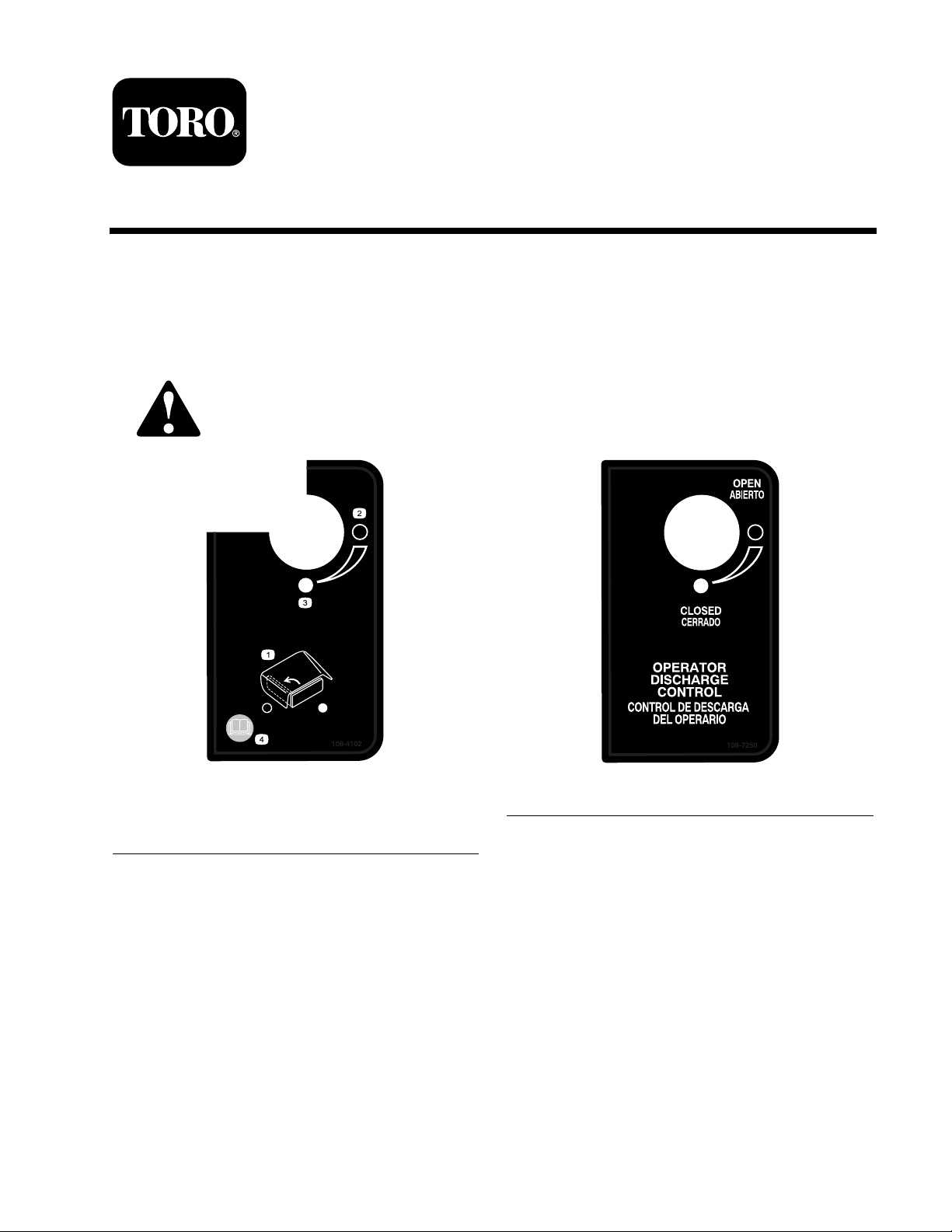
Safety and Instructional Decals
Safety decals and instr uctions are easily visible to the operator and are located near any
area of potential dang er . R e place any decal that is damag ed or lost.
Form No. 3357-563 Rev A
Installation Instructions
108-4102
1. Operator discharge control 3. Closed
2. Open
© 2006—The Toro® Company
8111 Lyndale Avenue South
Bloomington, MN 55420
108-7250
4. Read the Operator’s
Manual.
Register at www.Toro.com. Original Instructions (EN)
Printed in the USA.
All Rights Reserved
Page 2
Installation
Loose Parts
Use the chart below to verify that all parts have been shipped.
Step
1
2
3
4
5
No parts required
Side discharge chute
Bolt, (5/16 x 7–1/2 inches)
Locknut, (5/16 inch)
Plastic spacer
Spring
Handle assembly
Bolt, 3/8 x 3 inches
Small R-clamp (for 48 inch mowers)
Large R-clamp (for 52, 60 and 72
inch mowers)
Bolt, (5/16 x 3/4 inch)
Locknut, (5/16 inch)
Bolt, (3/8 x 1 inch)
Plastic cable ties
Adhesive back mount
Locknut, (3/8 inch)
International decal
Description
Qty.
–
1
1
1
1
1
1
1
1
1
1
1
1
1
1
1
1
Remove the existing side discharge
chute.
Install the side discharge chute with
gate.
Install the handle to the
height-of-cut panel.
Secure the cables.
Install the decal for international
mowers only.
Use
Step
1
Removing the Existing Side
Discharge Chute
No Parts Required
Procedure
1. Diseng ag e the PTO , set the parking brak e , and
c hoc k or bloc k the dri v e wheels .
2. T ur n off the engine , remo v e the k ey , and w ait
for all mo ving par ts to stop before lea ving the
operating position.
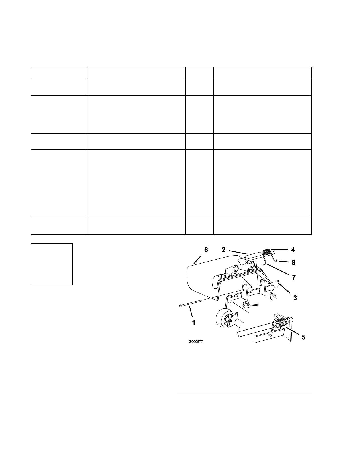
3. R emo v e the loc kn ut, bolt, spring and spacer
holding the deflector to the pi v ot brac k ets
( Figure 1 ). R emo v e the g rass deflector .
Figure 1
1. Bolt 5. Spring installed
2. Spacer
3. Locknut 7. L end of spring, place
4. Spring
6. Grass Deector
behind deck edge before
installing bolt
8. J hook end of spring
2
Page 3
Step
2
Installing the Side Discharge
Chute with Gate
Parts needed for this step:
1
Side discharge chute
1
Bolt, (5/16 x 7–1/2 inches)
1
Locknut, (5/16 inch)
1
Plastic spacer
1
Spring
Procedure
An unco v er ed discharge opening could
allo w the la wn mo w er to thr o w objects in
the operator’ s or bystander’ s dir ection and
r esult in serious injur y . Also, contact with
the blade could occur .
• Nev er operate the la wn mo w er unless
y ou install a co v er plate, a mulch plate, or
a g rass chute and catcher .
• Mak e sur e the g rass deflector is in the
do wn position.
Note: Ensure the g rass deflector is installed in
the lo w er holes in the mo w er dec k brac k ets .
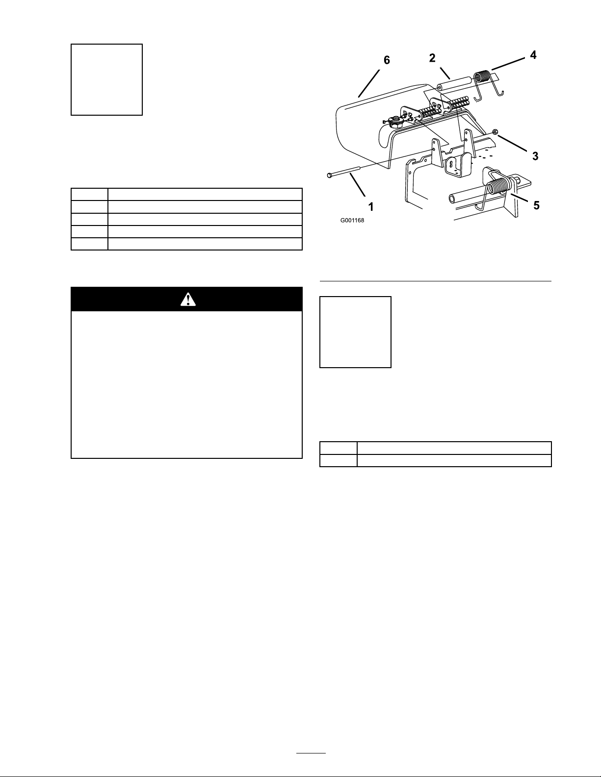
1. Place the new spacer and spring onto g rass
deflector . Place one end of spring behind dec k
edg e .
Note: Mak e sure the end of the spring is
installed behind the dec k edg e before installing
the bolt as sho wn in .
Figure 2
1. Bolt
2. Spacer
3. Locknut 6. Grass Deector
4. Spring
5. Spring installed
Step
3
Installing the Handle to the
Height-of-Cut Panel
Parts needed for this step:
1
Handle assembly
1
Bolt, 3/8 x 3 inches
Procedure
1. R emo v e the top bolt that holds the
height-of-cut panel and pin with lanyard to the
mac hine ( Figure 3 ). Discard the bolt.
2. Loosen the bottom bolt that holds the
height-of-cut panel to the mac hine ( Figure 3 ).
2. Install bolt and n ut in the lo w er hole . Place the
end of the spring around the g rass deflector
( Figure 2 ).
3. Tighten the n ut until the end of the bolt is flush
with the end of the n ut. Do not o v er tighten.
Important: T he g rass deflector must be
a ble to lo w er do wn into position. Lift the
deflector up to test that it lo w er s into the
full do wn position.
3
Page 4

Figure 3
1. Height-of-cut handle 5. Locknut
2. Handle assembly
3. Bolt, 3/8 x 3 inches 7. Bottom bolt
4. Pin and lanyard 8. Install slot between bolt
6. Spacer
head and height-of-cut
plate
Figure 4
1. Handle assembly 3. Z 400 upper hole
2. Z 500 upper hole 4. Slot for installing
Step
4
3. Slide the slot at the bottom of the handle
assembly in betw een the bottom bolt head and
the height-of-cut panel ( Figure 3 and Figure 4 ).
4. Using the new bolt (3/8 x 3 inc hes) and
hardw are previously remo v ed, install the handle
assembly to the outside of the height-of-cut
panel ( Figure 3 ). See Figure 4 for the cor rect
hole to use in the handle assembly .
Securing the Cables
Parts needed for this step:
1
Small R-clamp (for 48 inch mowers)
1
Large R-clamp (for 52, 60 and 72 inch mowers)
1
Bolt, (5/16 x 3/4 inch)
1
Locknut, (5/16 inch)
1
Bolt, (3/8 x 1 inch)
1
Plastic cable ties
1
Adhesive back mount
1
Locknut, (3/8 inch)
Procedure
Secure the cables to the mo w er dec k to ensure
the cables do not interfere with the rear tires .
Use the follo wing figures for the cor rect dec k
configuration that y our mac hine has .
1. F or mo w er dec ks with a roller brac k et, remo v e
the existing upper bolt from the right rear
g aug e wheel brac k et. Sa v e the loc kn ut and
discard the bolt.
4
Page 5

2. Install the larg e R-clamp to the outside of the
mo w er dec k and g aug e wheel brac k et with a
bolt (3/8 x 1 inc h) and new loc kn ut ( Figure 5 ).
Figure 5
1. Right rear gauge wheel and
bracket
2. Large R-clamp 5. Cables
3. Locknut, (5/16 inch)
4. Bolt, (5/16 x 1 inch)
1. Small R-clamp
2. Existing hole in mower
deck
Figure 7
3. Locknut, (5/16 inch)
4. Bolt, (5/16 x 3/4 inch)
3. F or mo w er dec ks with a pi v ot tube , secure the
cables with a plastic cable tie ( Figure 6 ).
Figure 6
1. Plastic cable tie 3. Pivot tube
2. Cables
5. F or all other mo w ers , install the adhesi v e bac k
plastic mount on a smooth clean surface .
T hread the cable tie through the plastic mount
and secure the cables with the cable tie ( Figure
8 ).
Figure 8
1. Plastic cable tie 3. Plastic mount
2. Cables
4. F or 48 inc h mo w ers , install the small R-clamp
to the mo w er dec k with a bolt (5/16 x 3/4
inc h) and loc kn ut (5/16 inc h) using the existing
hole in the right rear top of the dec k ( Figure 7 ).
5
Page 6

Step
Operation
5
Installing the Decal for
International Mowers Only
Parts needed for this step:
1
International decal
Procedure
Install the decal o v er the existing decal ( Figure 7 ).
Using the Chute Gate
T he chute gate does not seal the discharge
opening . Grass and objects maybe thr o wn in
a bystander’ s dir ection and r esult in serious
injur y .
• Be a w ar e of the mo w er discharge
dir ection and do not point it at an y one.
• R emo v e obstacles such as r ocks, tr ee
limbs, etc . fr om the mo wing ar ea.
• Nev er put y our hands or feet under the
mo w er or discharge ar ea.
• Nev er tr y to clear the discharge ar ea or
mo w er blades unless the engine is of f
and the k ey is r emo v ed.
Use the c hute g ate to temporarily stop or deflect
g rass clippings a w a y from sidew alks , parking
lots , patios , or anywhere y ou do not w ant g rass
clippings to land. T he c hute g ate has 3 positions:
open, 45 deg ree angle , and closed.
Figure 9
1. Existing decal 3. International decal
2. Handle
• R otate the c hute g ate handle to the open
position to allo w g rass clippings to disc harg e
(Figure Figure 10 ).
• R otate the c hute g ate handle to the 45
deg ree angle to deflect the g rass clippings
(Figure Figure 10 ).
• R otate the c hute g ate handle to the
closed position to stop the g rass clippings
(Figure Figure 10 ).
6
Page 7

Figure 10
1. Chute gate open 3. Chute gate closed
2. Chute gate at 45 degree
angle
7
Page 8

 Loading...