

Page 1
ChuteGateKit
34inand40inMowerDecksforZ300SeriesZMasterRiding
Mowers
ModelNo.78520
Safety
SafetyandInstructionalDecals
Safetydecalsandinstructionsareeasilyvisibletotheoperatorandarelocatednearanyareaof
potentialdanger.Replaceanydecalthatisdamagedorlost.
FormNo.3358-424RevA
InstallationInstructions
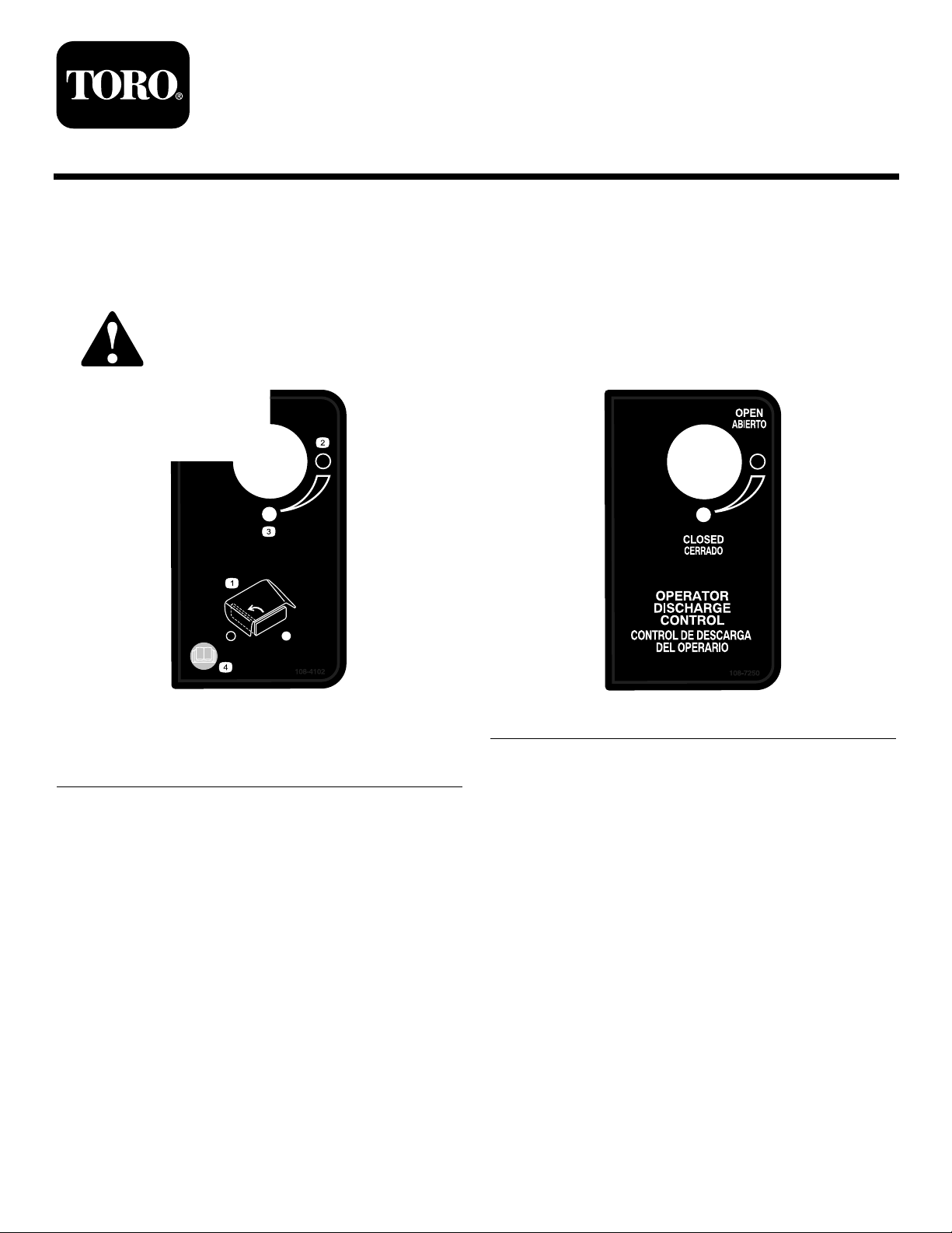
108-4102
1.Operatordischargecontrol3.Closed
2.Open4.ReadtheOperator’s
Manual.
108-7250
©2007—TheT oro®Company
8111LyndaleAvenueSouth
Bloomington,MN55420
Registeratwww.Toro.com.
OriginalInstructions(EN)
PrintedintheUSA.
AllRightsReserved
Page 2

Installation
LooseParts
Usethechartbelowtoverifythatallpartshavebeenshipped.
ProcedureDescription
1
2
3
4
5
Nopartsrequired
Sidedischargechute
Bolt,(5/16x7–1/2inches)
Locknut,(5/16inch)
Plasticspacer1
Spring
Handleassembly1Installthehandletothemachine.
Plasticcableties2
Adhesivebackmount2
Internationaldecal1
1
RemovingtheExistingSide
DischargeChute
Qty.
Use
–
1
1
1
1
Removetheexistingsidedischarge
chute.
Installthesidedischargechutewith
gate.
Securethecables.
Installthedecalforinternationalmowers
only.
NoPartsRequired
Procedure
1.DisengagethePTO,settheparkingbrake,andchock
orblockthedrivewheels.
2.Turnofftheengine,removethekey,andwaitforall
movingpartstostopbeforeleavingtheoperating
position.
3.Removethelocknut,bolt,springandspacerholding
thedeectortothepivotbrackets(Figure1).
Removethegrassdeector.
2
Page 3
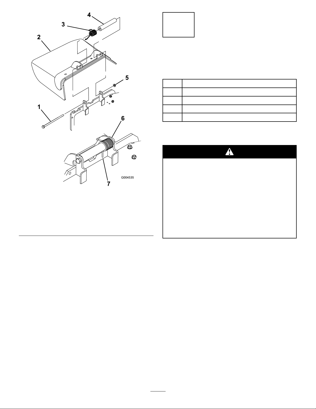
Figure1
1.Bolt5.Locknut
2.GrassDeector6.Springinstalled
3.Spring7.Jhookendofspring
placedbehinddeckedge
beforeinstallingbolt
4.Spacer
2
InstallingtheSideDischarge
ChutewithGate
Partsneededforthisprocedure:
1
Sidedischargechute
1
Bolt,(5/16x7–1/2inches)
1
Locknut,(5/16inch)
1Plasticspacer
1
Spring
Procedure
Anuncovereddischargeopeningcouldallow
thelawnmowertothrowobjectsinthe
operator’sorbystander’sdirectionandresult
inseriousinjury.Also,contactwiththeblade
couldoccur.
•Neveroperatethelawnmowerunlessyou
installacoverplate,amulchplate,oragrass
chuteandcatcher.
•Makesurethegrassdeectorisinthedown
position.
1.Placethenewspacerandspringontograssdeector.
Placeoneendofspringbehinddeckedge.
Note:Makesuretheendofthespringisinstalled
behindthedeckedgebeforeinstallingtheboltas
showninFigure2.
2.Installtheboltandnut.Placetheendofthespring
abovethedeectorbracket(Figure2).
3.Tightenthenutuntiltheendoftheboltisushwith
theendofthenut.Donotovertighten.
Important:Thegrassdeectormustbeableto
lowerdownintoposition.Liftthedeectorup
totestthatitlowersintothefulldownposition.
3
Page 4

Figure2
1.GrassDeector5.Endofthespringis
2.Spacer6.Springinstalled
3.Spring
4.Locknut
installedbehindthedeck
edge
7.Bolt
3
InstallingtheHandletothe
Machine
Partsneededforthisprocedure:
1Handleassembly
Procedure
Figure3
1.Fueltank4.Bottombolt
2.Tankbracket5.Locknut
3.Washer
4.Installthehandlewherethetankbracketwaswith
thepreviouslyremovednutsandbolts(Figure3).
5.Rotatethetankintothehandle/bracketandsecure
thebottomwiththepreviouslyremovedwasherand
bolt(Figure3).
6.Carriagebolt
1.Removethebottomboltandwasherthatholdsthe
rightsidegastanktothemachine(Figure3).
2.Rotatethetankawayfromthemachine.
3.Removethetankbracketfromthesideofthe
machine(Figure3).Savetheboltsandnuts.
Figure4
1.Fueltank3.Locknut
2.Carriagebolt4.Handle/bracket
4
Page 5

Figure5
1.Handle3.Bottombolt
2.Washer
Figure6
1.Plasticcabletie3.Plasticmount
2.Ensurethecablesdonot
getpinchedorkinkedhere
4
SecuringtheCables
Partsneededforthisprocedure:
2Plasticcableties
2Adhesivebackmount
Procedure
Securethecablestothemowerdecktoensurethecables
donotinterferewiththereartires.Usethefollowing
guresforthecorrectdeckcongurationthatyour
machinehas.
1.Lowerthemowerdecktothelowestposition.
2.Useonlyoneplasticmountandplastictieandsave
theotherforaspare.Installtheadhesivebackplastic
mountonasmoothcleansurfacewherethecables
willnotbepinchedorkinkedwhenthemowerdeck
israisedandlowered(Figure6).
5
InstallingtheDecalfor
InternationalMowersOnly
Partsneededforthisprocedure:
1Internationaldecal
Procedure
Installthedecalovertheexistingdecal(Figure7).
3.Threadthecabletiethroughtheplasticmountand
securethecableswiththecabletie(Figure6).
5
Page 6

Figure7
1.Existingdecal3.Internationaldecal
2.Handle
Operation
UsingtheChuteGate
Thechutegatedoesnotsealthedischarge
opening.Grassandobjectsmaybethrownin
abystander’sdirectionandresultinserious
injury.
•Beawareofthemowerdischargedirection
anddonotpointitatanyone.
•Removeobstaclessuchasrocks,treelimbs,
etc.fromthemowingarea.
•Neverputyourhandsorfeetunderthe
mowerordischargearea.
•Nevertrytoclearthedischargeareaor
mowerbladesunlesstheengineisoffand
thekeyisremoved.
Usethechutegatetotemporarilystopordeectgrass
clippingsawayfromsidewalks,parkinglots,patios,or
anywhereyoudonotwantgrassclippingstoland.The
chutegatehas3positions:open,45degreeangle,and
closed.
•Rotatethechutegatehandletotheopenpositionto
allowgrassclippingstodischarge(Figure8).
•Rotatethechutegatehandletothe45degreeangle
todeectthegrassclippings(Figure8).
•Rotatethechutegatehandletotheclosedposition
tostopthegrassclippings(Figure8).
6
Page 7

Figure8
1.Chutegateopen3.Chutegateclosed
2.Chutegateat45degree
angle
7
Page 8

 Loading...