

Page 1
FormNo.3358-540RevA
G001412
DFSVacCollectionSystem
foraZ593,Z595orZ589SeriesZMaster
Mower
ModelNo.78514—SerialNo.260000001andUp
Registeratwww.T oro.com.OriginalInstructions(EN)
Page 2
Introduction
1
G001411
Readthisinformationcarefullytolearnhowtooperate
andmaintainyourproductproperlyandtoavoid
injuryandproductdamage.Youareresponsiblefor
operatingtheproductproperlyandsafely.
YoumaycontactTorodirectlyatwww.Toro.comfor
productandaccessoryinformation,helpndinga
dealer,ortoregisteryourproduct.
Wheneveryouneedservice,genuineToroparts,
oradditionalinformation,contactanAuthorized
ServiceDealerorT oroCustomerServiceandhave
themodelandserialnumbersofyourproductready.
Figure1identiesthelocationofthemodelandserial
numbersontheproduct.Writethenumbersinthe
spaceprovided.
Figure1
1.Modelandserialnumberlocation
ModelNo.
SerialNo.
Thismanualidentiespotentialhazardsandhas
safetymessagesidentiedbythesafetyalertsymbol
(Figure2),whichsignalsahazardthatmaycause
seriousinjuryordeathifyoudonotfollowthe
recommendedprecautions.
Figure2
1.Safetyalertsymbol
Thismanualuses2otherwordstohighlight
information.Importantcallsattentiontospecial
mechanicalinformationandNoteemphasizesgeneral
informationworthyofspecialattention.
Contents
Introduction.................................................................2
Safety..........................................................................3
SafetyandInstructionalDecals...........................4
Setup...........................................................................5
1InstallingtheBaggerMounting
Bracket............................................................7
2TighteningallMountingBolts..........................9
3InstallingtheBaggerDrivePulley....................9
4InstallingtheSpringLoadedIdlerPulley
andSpringAnchor........................................10
5InstallingtheFixedIdlerPulley......................11
6InstallingtheIdlerArmBracket......................12
7InstallingtheBagger.......................................12
8InstallingtheBaggerBelt...............................13
9CheckingandAdjustingtheBaggerBelt
Tension..........................................................14
10InstallingtheWeights...................................14
11InstallingtheBootandDischarge
Tubes.............................................................15
12InstallingtheBaggerDumpHandle..............16
13InstallingtheBaggerDumpLeverStop
Bolt................................................................17
14AdjustingtheBaggerDumpLever................18
15ModifyingtheRadiatorCover......................18
16CheckingtheTirePressure...........................19
Operation...................................................................20
PositioningtheAdjustableBafe......................20
OpeningtheBagger...........................................20
HoldingtheBaggerDoorOpen.........................21
AdjustingtheBaggerDoorOpeningand
Cable.............................................................21
ClearingObstructionsFromtheBagger
System...........................................................21
RemovingtheDischargeTubes.........................22
RemovingtheBagger........................................22
SecuringtheBaggerIdlerPulley.......................23
ReplacingtheGrassDeector...........................23
OperatingTips...................................................24
Maintenance..............................................................26
RecommendedMaintenanceSchedule(s)..............26
CleaningtheScreens.........................................26
CleaningtheBagger..........................................26
CheckingtheBaggerBelt..................................26
GreasingtheIdlerArm......................................26
GreasingtheFanShaftBearings........................26
©2007—TheToro®Company
8111LyndaleAvenueSouth
Bloomington,MN55420
Contactusatwww.Toro.com.
2
PrintedintheUSA.
AllRightsReserved
Page 3

InspectingtheBagger........................................27
InspectingtheMowerBlades............................27
Troubleshooting........................................................28
Safety
Thefollowinglistcontainssafetyinformationspecic
toT oroproductsandothersafetyinformationyou
mustknow.
•Becomefamiliarwiththesafeoperationofthe
equipment,withtheoperatorcontrols,andsafety
signs.
•Useextracarewithgrasscatchersorother
attachments.Thesecanchangetheoperating
characteristicsandthestabilityofthemachine.
•Followthemanufacturer’srecommendations
foraddingorremovingwheelweightsor
counterweightstoimprovestability.
•Donotuseagrasscatcheronsteepslopes.A
heavygrasscatchercouldcauselossofcontrolor
overturnthemachine.
•Slowdownanduseextracareonhillsides.Be
suretotravelintherecommendeddirectionon
hillsides.Turfconditionscanaffectthemachine’s
stability.Useextremecautionwhileoperatingnear
drop-offs.
•Keepallmovementonslopesslowandgradual.
Donotmakesuddenchangesinspeed,directions
orturning.
•Thegrasscatchercanobstructtheviewtotherear.
Useextracarewhenoperatinginreverse.
•Usecarewhenloadingorunloadingthemachine
intoatrailerortruck
•Neveroperatewiththedischargedeectorraised,
removedoraltered,unlessusingagrasscatcher.
•Keephandsandfeetawayfrommovingparts.Do
notmakeadjustmentswiththeenginerunning.
•Stoponlevelground,disengagedrives,chock
orblockwheels,shutoffenginebeforeleaving
theoperator’spositionforanyreasonincluding
emptyingthegrasscatcheroruncloggingthechute.
•Ifyouremovethegrasscatcher,besuretoinstall
anydischargedeectororguardthatmighthave
beenremovedtoinstallthegrasscatcher.Donot
operatethemowerwithouteithertheentiregrass
catcherorthegrassdeectorinplace.
•Stoptheenginebeforeremovingthegrasscatcher
oruncloggingthechute.
•Donotleavegrassingrasscatcherforextended
periodsoftime.
•Grasscatchercomponentsaresubjecttowear,
damageanddeterioration,whichcouldexpose
movingpartsorallowobjectstobethrown.
Frequentlycheckcomponentsandreplace
3
Page 4

withmanufacturer’srecommendedparts,when
necessary.
SafetyandInstructionalDecals
Safetydecalsandinstructionsareeasilyvisibletotheoperatorandarelocatednearanyareaof
potentialdanger.Replaceanydecalthatisdamagedorlost.
107-1613
104-8569
106-3339
4
Page 5

Setup
LooseParts
Usethechartbelowtoverifythatallpartshavebeenshipped.
ProcedureDescription
1
2
3
4
5
6
7
8
Baggermountingbracket1
Sidebracket—right
Sidebracket—left
Longframespacer
Shortframespacer
Bolt,(3/8x1-1/2inches)
Bolt,(3/8x1-1/4inches)
Serratedangenut,(3/8inch)
Stiffenerbracket
Bolt,(3/8x3/4inch)
Curvedwasher
Roundspacers2
Bolt,(3/8x1inch)
Sidelocknut,(3/8inch)
Nopartsrequired
Baggerdrivepulley1
Pulleyspacer3
Bolt,(3/8x1-3/4inches)
Flangenut,(3/8inch)
Springloadedidlerpulley
Idlerarm1
Carriagebolt,(3/8x2inches)
Bolt,(3/8x4–1/2inches)
Locknut,(3/8inch)
Washer,7/16inch
Washer,13/32inch
Longroundspacer1
Sidelocknut,(3/8inch)
Springanchor,(3/8inch)
Fixedidlerpulley1
Fixedidlerbracket1
Bolt,(3/8x1-1/2inches)
Bolt,(3/8x3/4inch)
Locknut,(3/8inch)
Flangenut,(3/8inch)
Washer,13/32inch
Idlerarmbracket1
Bolt,(3/8x3/4inch)
Flangenut,(3/8inch)
Bagger1
Clevispin
Hairpincotter2
Baggerbelt1
Spring
Qty.
16
29
14
Use
1
1
2
2
2
2
8
2
1
–
3
3
1
1
1
2
1
1
1
1
1
2
1
2
1
2
2
2
1
Installthebaggermountingbrackets
ontothemachine
Tightenallmountingbolts
Installthebaggerdrivepulley
Installthespringloadedidlerpulley
Installthexedidlerpulley
Installtheidlerarmbracket.
Installthebagger
Installthebaggerbelt
5
Page 6

ProcedureDescription
Qty.
Use
9
10
11
12
13
14
Nopartsrequired
Casterweight
U-bolt2
Nut,(1/2inch)
Lockwasher,(1/2inch)
Plate2
Smalltopweight
Largetopweight1
Bolt,1/2x4inch-fortopweights
Boot1
Middletube1
Uppertube1
Clamp
Dumphandle1
Washers,13/16inch
Cotterpin
Bolt,(1/2x1-3/4inches)
Jamnuts,(1/2inch)
Longcableclevis1
Nopartsrequired
–
2
4
4
2
2
1
2
1
1
2
–
Checkandadjustthebaggerbelt.
Installtheweights
Installthebootanddischargetubes
Installthebaggerdumphandle
Installthebaggerdumpleverstopbolt
Adjustthebaggerdumplever
15
16
Nopartsrequired
Nopartsrequired
–
–
Note:Determinetheleftandrightsidesofthemachinefromthenormaloperatingposition.
ModifytheRadiatorCover
Checkthetirepressure
6
Page 7
1
InstallingtheBaggerMounting
Bracket
Partsneededforthisprocedure:
1Baggermountingbracket
1
Sidebracket—right
1
Sidebracket—left
2
Longframespacer
2
Shortframespacer
16
Bolt,(3/8x1-1/2inches)
2
Bolt,(3/8x1-1/4inches)
29
Serratedangenut,(3/8inch)
2
Stiffenerbracket
8
Bolt,(3/8x3/4inch)
14
Curvedwasher
2Roundspacers
2
Bolt,(3/8x1inch)
1
Sidelocknut,(3/8inch)
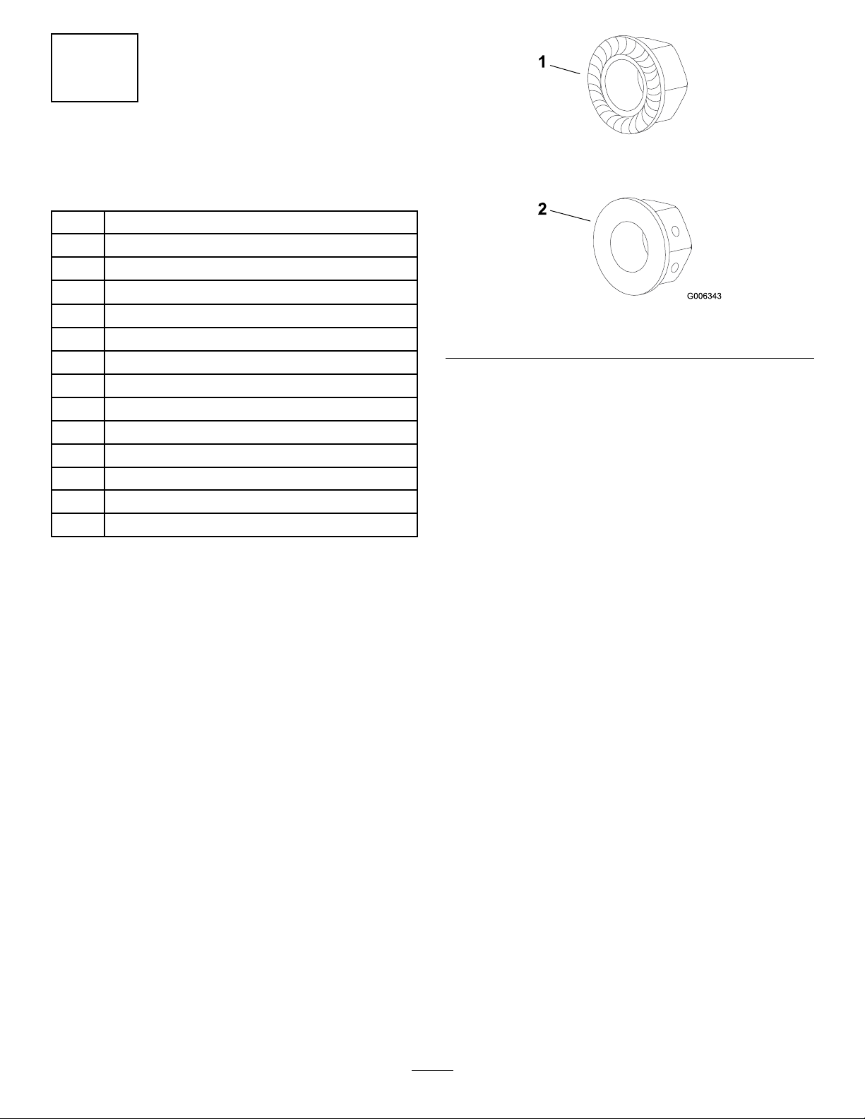
Procedure
Important:Donottightenanyboltsuntilbothside
bracketsandbaggermountingbracketaretloose
onthemachine.
RefertoTighteningtheMountingBoltsforthe
correctproceduretotightenthebolts.
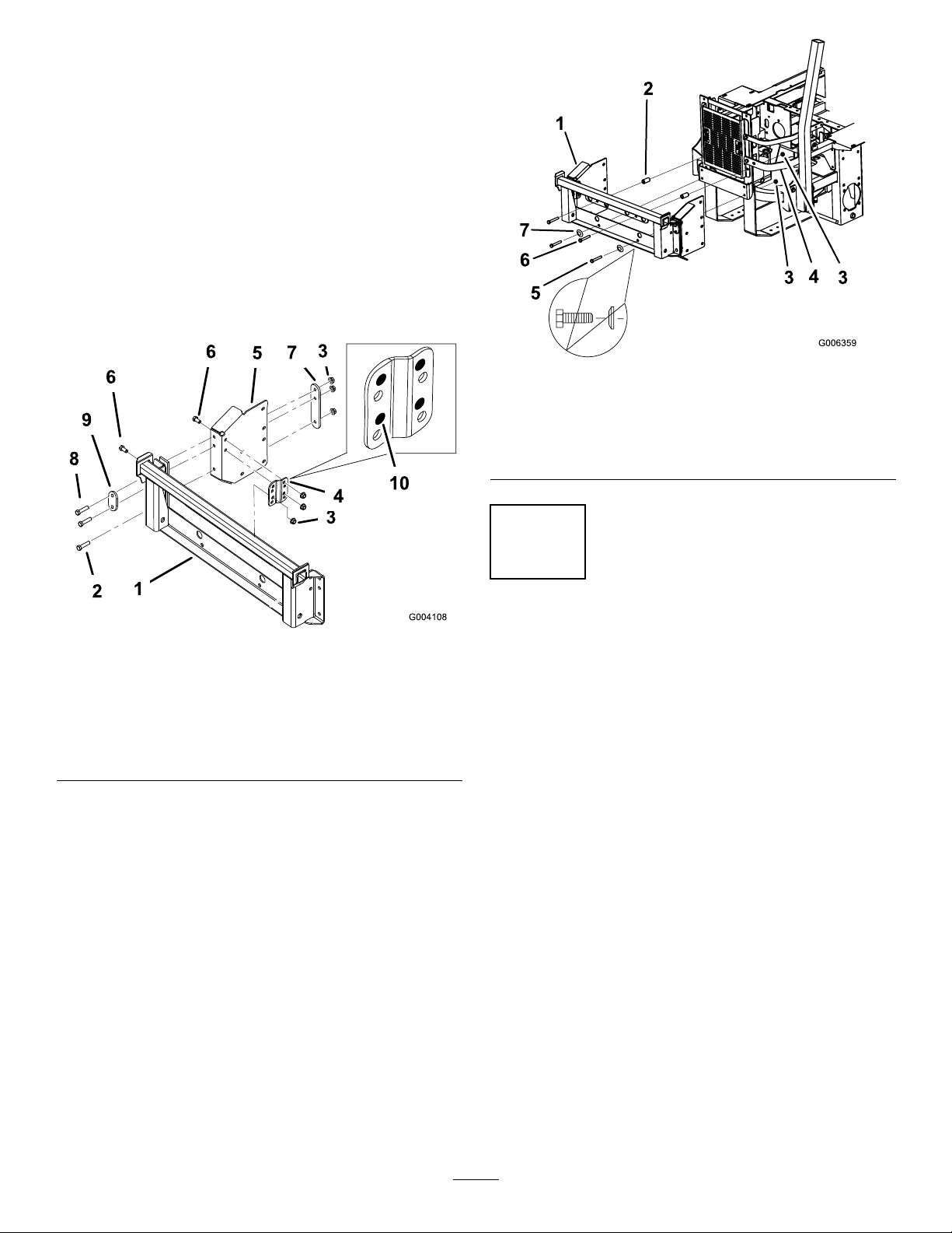
Figure3
1.Seratedlocknut2.Sidelocknut
1.Installtherightsidebrackettothebaggermounting
bracket(Figure4).
2.Inthetoptwoholes,install2bolts(3/8x1-1/2
inches),2angenuts(3/8inch),1longframe
spacer,andoneshortframespacer(Figure4).
Note:Makesurethelongframespacerisinstalled
asshowninFigure4).
3.Inthebottomhole,installabolt(3/8x1-1/4
inches)andaangenut(3/8inch)(Figure4).
4.Installabracketstiffenertotherightsidebracket
andbaggermountingbracket.Use4bolts(3/8x
3/4inch)and4angenuts(3/8inch)(Figure4).
UseFigure3fordeterminingthedifferencesbetween
theserratedlocknutsandthesidelocknut.
7
Page 8
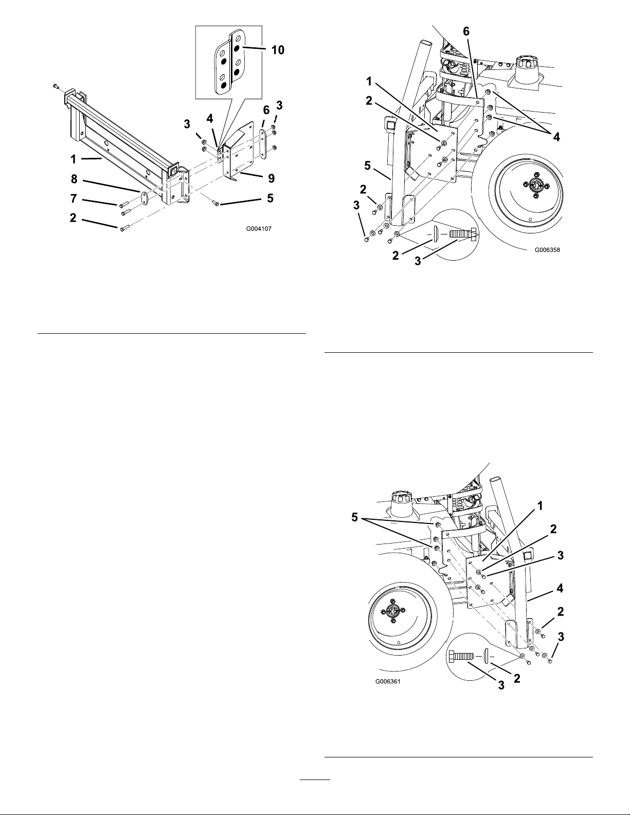
Figure4
1.Baggermountingbracket
2.Bolt,(3/8x1-1/4inches)7.Bolt,(3/8x1-1/2inches)
3.Flangenut,(3/8inch)8.Shortframespacer
4.Bracketstiffener
5.Bolt,(3/8x3/4inch)
6.Longframespacer
9.Rightsidebracket
10.Usetheseholesinthe
bracketstiffener
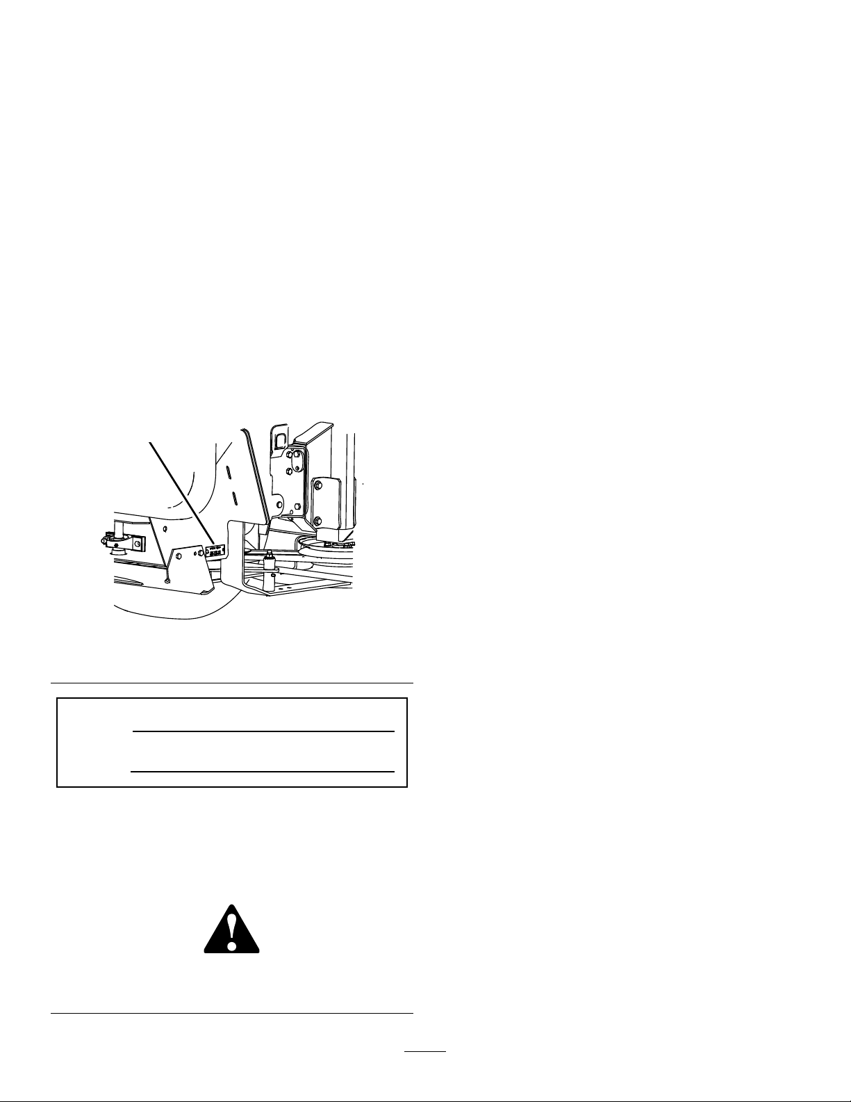
5.Removethebolts,nuts,andwashersholdingthe
rollbartotherightsideofthemachine.Discard
thenuts,bolts,andwashers(Figure5).
6.Removetheexistingboltandnutholdingthe
engineguardasshowninFigure5.
7.Installtherightsidebracketandtherollbarsection
tothesideofthemachineusing6bolts(3/8x1-1/2
inches),6curvedwashers(3/8inch),and6ange
nuts(3/8inch)(Figure5).
Note:Makesurethecurvedwasherareinstalledas
showninFigure5.
Figure5
1.Sidebracket4.Flangenut,(3/8inch)
2.Curvedwasher,(3/8inch)5.ROPS
3.Bolt,(3/8x1-1/2inches)
6.Removetheexistingbolt
fromengineguardand
discard
8.Removethebolts,nuts,andwashersholdingthe
rollbartotheleftsideofthemachine.Discardthe
nuts,bolts,andwashers(Figure6).
9.Installtheleftsidebracketbetweentherollbar
sectionandthesideofthemachineandfastenwith
6bolts(3/8x1-1/2inches),6curvedwashers(3/8
inch),and6angenuts(3/8inch)(Figure6).
Figure6
1.Sidebracket4.ROPS
2.Curvedwasher,(3/8inch)5.Flangenut,(3/8inch)
3.Bolt,(3/8x1-1/2inches)
8
Page 9
10.Installtheleftsidebrackettothebaggermounting
bracket(Figure7).
11.Inthetoptwoholes,install2bolts(3/8x1-1/2
inches),2angenuts(3/8inch),1longframe
spacer,andoneshortframespacer(Figure7).
Note:Makesurethelongframespacerisinstalled
asshowninFigure7.
12.Inthebottomhole,installabolt(3/8x1-1/4
inches)andaangenut(3/8inch)(Figure7).
13.Installabracketstiffenertotheleftsidebracket
andbaggermountingbracket.Use4bolts(3/8x
3/4inch)and4angenuts(3/8inch)(Figure7).
Figure8
1.Baggermountingbracket
2.Roundspacer
3.Flangenut,(3/8inch)7.Curvedwasher,(3/8inch)
4.Bumper
5.Bolt,(3/8x1inch)
6.Bolt,(3/8x1-3/4inches)
Figure7
1.Baggermountingbracket
2.Bolt,(3/8x1-1/4inches)7.Longframespacer
3.Flangenut,(3/8inch)8.Bolt,(3/8x1-1/2inches)
4.Bracketstiffener9.Shortframespacer
5.Leftsidebracket
6.Bolt,(3/8x3/4inch)
10.Usetheseholesinthe
bracketstiffener
14.Inthetoptwoholes,install2bolts(3/8x1-3/4
inches),2roundspacers,and2angenuts(3/8
inch).
15.Inthebottomtwoholes,install2bolts(3/8x1
inch)and2angenuts(3/8inch)(Figure8).
2
TighteningallMountingBolts
NoPartsRequired
Procedure
Thefollowingstepsarethecorrectsequencetotighten
thesidebracketsandthebaggermountingbracket.
All3/8inchmountingboltsneedtobetorquedto
35ft-lb(48N⋅m).
1.Tightenthebaggermountingbrackettotherear
framerst(Figure8).
2.Tightenthebaggermountingbrackettotheside
brackets(Figure4).
3.Tightenthebracketstiffenerstoboththesideplates
andthebaggermountingbracket(Figure4).
4.Tightenthesidebracketstothesideofthemower
(Figure6).
9
Page 10
3
InstallingtheBaggerDrive
Pulley
Partsneededforthisprocedure:
1Baggerdrivepulley
3Pulleyspacer
3
Bolt,(3/8x1-3/4inches)
3
Flangenut,(3/8inch)
Procedure
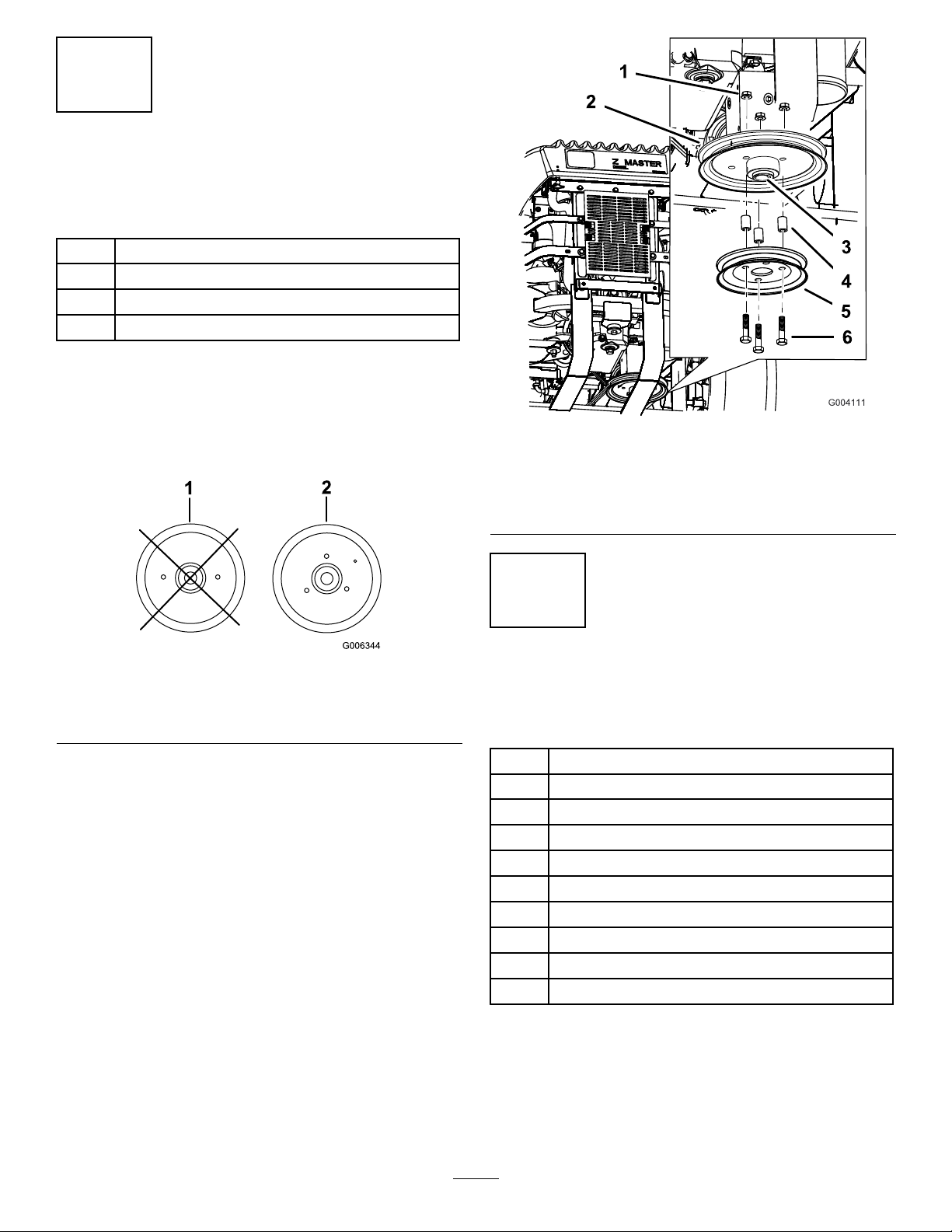
Note:Makesurethegearboxpulleyhas4holesaround
thecenterhole(Figure9).Ifitdoesnot,contactan
AuthorizedServiceDealerforthecorrectpulley.
Figure9
1.Donotusethisgearbox
pulley
2.Usethisgearboxpulley
with4holesaroundthe
centerhole
Note:Makesurethegearboxpulleyisushtothe
bottomofthegearboxshaft(Figure10).
Installthebaggerdrivepulleytothegearboxpulley
with3bolts(3/8x1-3/4inches),3spacers,and
3angenuts(3/8inch)(Figure10).
Figure10
1.Flangenut,(3/8inch)4.Spacer
2.Gearboxpulley
3.Gearboxpulleyisush
withgearboxshaft.
4
InstallingtheSpringLoaded
IdlerPulleyandSpringAnchor
Partsneededforthisprocedure:
1
Springloadedidlerpulley
1Idlerarm
1
Carriagebolt,(3/8x2inches)
1
Bolt,(3/8x4–1/2inches)
2
Locknut,(3/8inch)
1
Washer,7/16inch
1
Washer,13/32inch
1Longroundspacer
1
Sidelocknut,(3/8inch)
1
Springanchor,(3/8inch)
5.Baggerdrivepulley
6.Bolt,(1/2x1-3/4inch)
Procedure
Note:InstalltheGussetKitatthesametimeas
installingtheidlerpulleyandthespringanchor.This
willeliminateduplicatesteps.TheGussetKitcanbe
obtainedfromanAuthorizedServiceDealer.
10
Page 11

UseFigure11fordeterminingthedifferencesbetween
1
2
3
1
4
5
6
7
8
G001405
9
10
11
12
13
theserratedlocknutsandthesidelocknut.
Figure11
1.Serratedlocknut2.Sidelocknut
1.Installthespringloadedidlerpulleytotheidler
armwithacarriagebolt(3/8x2inches),washer
(13/32inches),andalocknut(3/8inch).
2.Installthespringloadedidlerpulleytotheright
rearbottomframewithabolt(3/8x4inches),long
spacer,washer(7/16inches),andalocknut(3/8
inch)(Figure12).
Figure12
1.Locknut,(3/8inch)8.Rightrearbottomframe
2.Washer,7/16inch9.Springanchor
3.Springloadedidlerpulley10.Sidelocknut,(3/8inch)
4.Washer,13/32inch11.Bolt,(3/8x4–1/2inch
5.Longroundspacer
6.Idlerarm
7.Carriagebolt,(3/8x2
inches)
12.Leftrearbottomframe
13.Rightrearbottomframe
Important:Makesuretheidlerarmandspring
anchorisinstalledinthecorrectholesshown
inFigure12.
5
InstallingtheFixedIdlerPulley
Partsneededforthisprocedure:
1Fixedidlerpulley
1Fixedidlerbracket
1
Bolt,(3/8x1-1/2inches)
2
Bolt,(3/8x3/4inch)
1
Locknut,(3/8inch)
2
Flangenut,(3/8inch)
1
Washer,13/32inch
Procedure
1.Installthexedidlerpulleytothexedidler
bracketwithabolt(3/8x1-1/2inches),washer
(13/32inches),andalocknut(3/8inch).
11
Page 12

2.Installthexedidlerassemblytotheleftrear
G001406
1
2
3
4
5
6
7
8
bottomframewith2bolts(3/8x3/4inch)and2
angenuts(3/8inch)(Figure13).
Figure13
1.Fixedidlerpulley
2.Washer,(13/32inch)
3.Locknut,(3/8inch)7.Leftrearbottomframe
4.Flangenut,(3/8inch)8.Bolt,(3/8x3/4inch)
5.Bolt,(3/8x1-1/2inches)
6.FixedIdlerpulleybracket
Figure14
1.Bolt,(3/8x3/4inch)3.Nut,(3/8inch)
2.idlerarmbracket4.Idlerpulley
7
6
InstallingtheIdlerArmBracket
Partsneededforthisprocedure:
1Idlerarmbracket
2
Bolt,(3/8x3/4inch)
2
Flangenut,(3/8inch)
Procedure
Installtheidlerarmbrackettotherightrearbottom
framewith2bolts(3/8x3/4inch)and2angenuts
(3/8inch)(Figure14).
InstallingtheBagger
Partsneededforthisprocedure:
1Bagger
2
Clevispin
2Hairpincotter
Procedure
1.Installthebaggerontothebaggermounting
bracketFigure15
2.Installthe2clevispinsintothebaggerandbagger
mountingbracket.Securethemwith2hairpin
cottersFigure15
12
Page 13

G001402
2
3
4
1
Figure15
1
2
3
4
5
6
G001407
1.Bagger3.Hairpincotter
2.Baggermountingbracket
4.Clevispin
3.Removethecableguideandboltfromtheframeof
thebagger(Figure16).
4.Installthecableguide,bolt,andnutwiththecable
behindthecableguide(Figure16).
8
InstallingtheBaggerBelt
Partsneededforthisprocedure:
1Baggerbelt
1
Spring
Procedure
1.Routethebaggerbeltaroundthedrivepulleyand
thebaggerpulley(Figure17).
Note:Makesurethecableguidecanrotate.
Figure16
1.Cable3.Cableclevis
2.Cablebehindthecable
guide
Figure17
1.Drivepulley4.Fixedidlerpulley
2.Baggerpulley
3.Springloadedidlerpulley
5.Skidplate
6.Baggerbelt
2.Installthespringontotheidlerarm(Figure18).
3.Routethebaggerbeltaroundthespringloaded
idlerpulleyandthexedidlerpulley(Figure18).
4.Installthespringontothespringanchorattached
totheleftrearbottomframe(Figure18).
13
Page 14

G001408
1
2
3
4
5
Figure18
1
2
3
4
5
G001886
6
G001365
1
2
3
1.Springloadedidlerpulley4.SpringAnchor
2.Fixedidlerpulley5.Belt
3.Spring
9
Figure19
1.Drivepulley4.Fixedidlerpulley
2.Baggerpulley5.Baggerbelt
3.Springloadedidlerpulley6.1–1/8inch±1/8inch(29
mm±3mm)
2.Ifthegapisnotcorrect,removethespring.
3.Toadjustthebelttensioncompletethefollowing:
A.Loosenthe2nutsonthelowerfanshaftpillow
block(Figure20).
B.Insertaspacerbehindthepillowblock
(Figure20).
C.Tightenthenuts.
CheckingandAdjustingthe
BaggerBeltTension
NoPartsRequired
Procedure
1.Measurethegap,atthebaggertensionerpulley,
betweenthetightandslacksideofthebeltwhen
thebaggertensionerpulleyandspringareinstalled
(Figure18).Thereneedstobeagapof1-1/8inch
±1/8inch(29mm±3mm)betweenthebelt
strands(Figure19).
D.Checkthebeltgapandrepeatprocedureas
required.
Figure20
1.Pillowblock
2.Fanshaft
3.Spacer
14
Page 15

10
1
2
3
4
6
1
5
G001366
2
1
3
4
5
G001409
InstallingtheWeights
Partsneededforthisprocedure:
2
Casterweight
2U-bolt
4
Nut,(1/2inch)
4
Lockwasher,(1/2inch)
2Plate
2
Smalltopweight
1Largetopweight
2
Bolt,1/2x4inch-fortopweights
Figure21
1.Frontcasterweight4.Nut
2.U-bolt5.Frontcaster
3.Plate6.Lockwasher
Procedure
TocomplywithANSI/OPEIB71.4-2004Standard,
topweightsmustbeaddedtothemachine.
Thebaggeraddsalotofweighttotherear
ofthemachineandmaycauseanunstable
conditionwhichcouldresultinalossofcontrol.
1.Placecasterweightsonthefrontcasters.
2.Installplate,nuts(1/2inch)andlockwasher
(1/2inch)undertheframeandweight(Figure21).
3.Repeatforoppositeside.
Note:ZMastermowerswith52inchmowerdecks
requireadditionalweightifnoZStand®isinstalled.
ContactyourAuthorizedServiceDealerforthe
weightkit.
4.Installthealargetopweightsontopofeachcaster
weight(Figure22).
5.Installthe2smalltopweightsontopofeachlarge
topweightandsecurethemwithabolt(1/2x4
inches)(Figure22).
1.Topweight3.Frontcasterweight
2.Bolt,(1/2x4inches)
Figure22
4.Frontcasterwheel
15
Page 16

6.Placetherearhookovertherearofthemounting
G001369
1
2
3
4
5
6
7
8
9
10
11
bracket(Figure24).
11
InstallingtheBootand
DischargeTubes
Partsneededforthisprocedure:
1Boot
1Middletube
1Uppertube
1
Clamp
Procedure
Note:RemembertoreplacetheLorthestraightend
ofthespringwheninsidedischargemode.Referto
ReplacingtheGrassDeector.
1.DisengagethePTOandsettheparkingbrake.
2.Stoptheengine,removethekey,andwaitforall
movingpartstostopbeforeleavingtheoperating
position.
7.Installtheuppertubeintothebagger(Figure24).
8.Slidetheclampontothemiddletube(Figure24).
9.Aligntheknobonthemiddletubewiththenotch
intheuppertube.Slidethemiddletubeintothe
uppertubeandtwistthemiddletube60degrees
(Figure24).
10.Tightentheclamparoundtheupperandmiddle
tubeconnection(Figure24).
11.Slidethemiddletubeontothebootandlatchthem
together(Figure24).
3.Torelievethespringtensiononthegrassdeector,
placetheLorthestraightendofthespringinfront
ofthemountingbracket.
4.Liftthegrassdeectorallthewayback.
5.Positiontheboot’sfronthookintothefrontsloton
themountingbracket(Figure24).
Note:Ifthegrassdeectorinterfereswiththe
boot,grindoffpartofthegrassdeectorframe.See
Figure23forthecorrectparttogrindoff.
Figure24
1.Boot7.Mountingbracket
2.Middletube8.Frontslot
3.Knob9.Rearhook
4.Uppertube10.Fronthook
5.Latch
6.Notchinuppertube
11.Clamp
Figure23
1.Grassdeectorframe2.Grindthispartoff
16
Page 17

12
1
2
3
4
5
G001372
6
7
8
13
InstallingtheBaggerDump
Handle
Partsneededforthisprocedure:
1Dumphandle
2
Washers,13/16inch
1
Cotterpin
Procedure
1.Unfastenthedumphandlefromthecrate.
2.Installawasherontothebaggerdumphandleand
installthebaggerdumphandleintothebagger
frame(Figure25).
3.Fastenthebaggerhandlewithawasher(13/16
inches)andacotterpin(Figure25).
InstallingtheBaggerDump
LeverStopBolt
Partsneededforthisprocedure:
1
Bolt,(1/2x1-3/4inches)
2
Jamnuts,(1/2inch)
1Longcableclevis
Procedure
1.Removethecotterpinandclevispinsecuringthe
baggercableclevistothebaggerdumphandle
(Figure26).
2.Threadajamnut(1/2inch)allthewayontothe
bolt(1/2x1-3/4inches)(Figure26).
3.Movethebaggerdumpleverforwardtomovethe
bottomoftheleverawayfromthestopbracket
(Figure26).
4.Inserttheboltintothestopbracketholeandthread
anotherjamnut(1/2inch)ontothebolt.Donot
tighten.
5.Securethebaggercableclevistothebaggerdump
handlewiththeclevispinandcotterpinpreviously
removed(Figure26).
Figure25
1.Dumphandle
2.Washer
3.Cotterpin
4.Baggerframe
Figure26
1.Baggerdumplever
2.Baggercable
3.Longcableclevis
4.Bolt,(1/2x1-3/4inches)8.Cotterpin
5.Jamnut,(1/2inch)
6.Stopbracket
7.Clevispin
17
Page 18

6.Installthebaggercableintothecableclevis
G001373
1
2
3
4
5
5
1
(Figure26).
7.Adjustthehandlestop,refertoAdjustingthe
BaggerDumpLever.
14
AdjustingtheBaggerDump
Lever
NoPartsRequired
Procedure
Thebaggerleverneedstobeadjustedtoremoveslack
inthebaggercable.
Important:Makesurethebaggerdoorislatched
beforeadjustingthelever.
1.Loosenthenutsonbothsidesofthestopbracket
(Figure27).
2.Adjustthestopboltuntilthereisnoslackinthe
baggercable(Figure27).
3.Tightenthenutsonbothsidesofthestopbracket
(Figure27).
15
ModifyingtheRadiatorCover
NoPartsRequired
Procedure
1.Locatetemplatenumber1inthebackofthis
manual.Cutouttemplatenumber1asindicatedon
thetemplate(Figure28).
2.Positionthetemplateontheright-handsideofthe
radiatorcover(Figure28).
3.Lineupthemarkonthetemplatewherethe
baggercableclevishitstheradiatorcoverandthe
templatebottomisushwiththebottomofcover
(Figure28).
4.Tapethetemplatetotheradiatorcover.Markthe
outeredgeofthetemplate(Figure28).
5.Cuttheradiatorcoveratthemarkedline.Thiswill
preventdamagetotheradiatorcoverwhileusing
thebaggerdumplever(Figure28).
Note:Makesuretofollowthetemplateoutline.Do
notcreateanysharpcorners.
Figure27
1.Baggerdumplever4.Baggercable
2.Stopbracket
3.Stopbolt
5.Nut
18
Page 19

Figure28
G001055
1.Cable
2.Cableguide
3.Nosharpcorners7.Baggercableclevis
4.Radiatorcover8.Markontemplatealigned
5.Baggerdumplever
6.Templatealignedwith
coverbottom
withclevis
Figure29
1.Valvestem
16
CheckingtheTirePressure
NoPartsRequired
Procedure
Note:Increasethetirepressureduetotheadditional
weight.
Checkandincreasetheairpressureinthefrontcaster
wheelsandreartires(Figure29).
Pressure:Reartires-20psi(90kPa)
Frontcasterwheels-25psi(90kPa)
19
Page 20

Operation
G000947
1
2
G001374
Note:Determinetheleftandrightsidesofthemachine
fromthenormaloperatingposition.
Important:Ifthemachineisonaslope,chock
orblockthewheelstopreventthemachinefrom
slowlyrolling.
Toavoidpersonalinjury,followthese
procedures:
•Becomefamiliarwithalloperatingand
safetyinstructionsintheoperator’smanual
foryourmowerbeforeusingthisattachment.
•Neverremovethebaggerorbaggertubes
whiletheengineisrunning.
•Alwaysshuttheengineoffandwaitforall
movingpartstostopbeforeclearingan
obstructionfromthebaggingsystem.
PositioningtheAdjustable
Bafe
AdjustthebafetopositionB(middleposition)for
bagging.RefertothemachinesOperatorManualfor
thebafeadjustmentprocedure.
Figure30
•Neverdomaintenanceorrepairswhilethe
engineisrunning.
Withoutthegrassdeector,baggertubesor
completebaggerassemblymountedinplace,
youandothersareexposedtobladecontact
andthrowndebris.Contactwiththerotating
mowerblade(s)andthrowndebriswillcause
injuryordeath.
•Neverremovethegrassdeectorfrom
themowerbecausethegrassdeector
routesmaterialdowntowardtheturf.Ifthe
grassdeectoriseverdamaged,replaceit
immediately.
•Neverputyourhandsorfeetunderthe
mower.
•Nevertrytoclearthedischargeareaor
mowerbladesunlessyoumovethepower
takeoff(PTO)tooffandrotatetheignition
keytooff.Alsoremovethekeyandpullthe
wireoffofthesparkplug(s).
OpeningtheBagger
1.DisengagethePTO.
2.Reachback,squeezeandreleasethelatchlever
againstthebaggerlever(Figure31).Thiswill
openthelatchthatsecuresthebaggerdoor.
3.Pulldownonthebaggerarmtoallowthegrassto
falloutofthebagger(Figure31).
4.Returnthebaggerarmtouprightpositioninone
quickmotion.Makesurethebaggerdoorfully
engagesintothelatch(Figure31).
Note:Makesurethebaggerlatchisfullyengaged
beforecollectinggrass.
Figure31
1.Baggerlever2.Latchlever
20
Page 21

HoldingtheBaggerDoorOpen
G001375
1
3
2
4
G001376
1
5
3
4
6
7
2
Hands,ngersandarmscangetpinched
betweenthebackandfrontsectionsofthe
collector.
•Keeppeopleawayfromcollectorwhile
emptyingit.
•Ifworkingontheinside,usetheholdingpin
toholdthecollectordooropen.
1.DisengagethePTO,settheparkingbrake,and
chockorblockthetires.
2.Turnofftheengine,removethekey,andwait
forallmovingpartstostopbeforeleavingthe
operatingposition.
3.Openthebagger;refertoOpeningtheBagger.
4.Withthebaggeropen,pullouttheholdingpinand
insertintotheholeinthehinge(Figure32).
2.Turnofftheengine,removethekey,andwait
forallmovingpartstostopbeforeleavingthe
operatingposition.
3.Closethebagger.
4.Removethecotterpinandclevispin(Figure33).
5.Adjustthebaggercabletothedesiredholeposition
(Figure33).
Note:Thelowerholewillallowthedoortoopen
higher.Theupperholewillallowlessforcetoopen
thedoorwhileusingthehandle.
6.Installtheclevispinandcotterpinintothebagger
andcableend(Figure33).
Figure32
1.Holdingpin
2.Holeinhinge(open)
3.Holeinhinge(storage)
4.Hinge
AdjustingtheBaggerDoor
OpeningandCable
Adjustingthecableatthetopofthebagger,canallow
thedoortoopenfartherforyourdesireconditions.
1.DisengagethePTO,settheparkingbrake,and
chockorblockthetires.
Figure33
1.Baggercable
2.Holesinbaggerdoor
hinge
3.Clevispin
4.Hinge
5.Cotterpin
6.Lowerhole-allowsdoorto
openhigher
7.Upperhole-allowsless
forcetoopendoor
ClearingObstructionsFrom
theBaggerSystem
1.Emptythebagger.
2.DisengagethePTOandsettheparkingbrake.
3.Stoptheengine,removethekey,andwaitforall
movingpartstostopbeforeleavingtheoperating
position.
4.Removethecompletetubeassemblyfromthe
baggerandboot.
5.Removethebootfromthemower.
21
Page 22

6.Usingastickorsimilarobject,carefullyremove
G001369
1
2
3
4
5
6
7
8
9
10
11
andcleartheobstructionfromthemower,upper
tube,middletube,orbootassembly.
7.Afteryouremovetheobstruction,installthe
completebaggersystemandresumeoperation.
RefertoInstallingtheDischargeTubes.
RemovingtheDischarge
Tubes
Note:RemembertoreplacetheLendofthespring
wheninsidedischargemode.RefertoReplacingthe
GrassDeector.
1.DisengagethePTOandsettheparkingbrake.
2.Stoptheengine,removethekey,andwaitforall
movingpartstostopbeforeleavingtheoperating
position.
3.Unlatchthemiddletubefromthebootandslide
apart(Figure34).
4.Removethetubeassemblyfromthebagger
(Figure34).
5.Removethebootfromthemountingbracket
(Figure34).
Figure34
1.Boot7.Mountingbracket
2.Middletube8.Frontslot
3.Knob9.Rearhook
4.Uppertube10.Fronthook
5.Latch
6.Notchinuppertube
11.Clamp
6.Lowerthegrassdeectorbackintoplace.
7.Ifyouarechangingtosidedischargemode,install
thegrassdeectorspring.RefertoReplacingthe
GrassDeector.
RemovingtheBagger
Ifyouoperatemowerwithoutthebagger
installedorwiththedischargetubesandboot
removed,youandothersmaybeinjuredby
throwndebrisorcutbytheblade.
Alwaysoperatethemowerwitheitherthe
completebaggermountedinplaceorusethe
mowerinsidedischarge.
1.Disengagethepowertakeoff(PTO),setthe
parkingbrake,turntheignitionkeytooffand
removethekey.
2.Removethedischargetubes.RefertoRemoving
theDischargeTubes.
3.Removehairpincottersandclevispinsfromthe
baggerandbaggerbracket.
4.Removetheskidplate.
5.Removethebaggerbeltandbaggeridlerpulley.
6.Removethebaggerfromthebaggermounting
bracket.
22
Page 23

7.Installtheskidplate.
G000977
1
2
3
4
5
6
7
8
8.Replacethegrassdeectorspring;referto
ReplacingtheGrassDeectorSpring.
ReplacingtheGrassDeector
9.Removeboththetopweightsandcasterweights.
SecuringtheBaggerIdler
Pulley
Forthisprocedure,useoneoftheclevispinsand
hairpincotterpinsusedtoattachthebaggertothe
baggermountingbracket.
Note:Onlysecurethebaggeridlerpulleywhenyou
areremovingthebagger.
1.Tosecuretheidlerarm,inserttheclevispinthrough
theidlerarmandidlerarmbracket(Figure35).
2.Installthehairpincotterpintosecuretheclevis
pin(Figure35).
Anuncovereddischargeopeningcouldallow
thelawnmowertothrowobjectsinthe
operator’sorbystander’sdirectionandresult
inseriousinjury.Also,contactwiththeblade
couldoccur.
Neveroperatethelawnmowerunlessyouinstall
acoverplate,amulchplate,oragrasschute
andcatcher.
1.Removethelocknut,bolt,springandspacer
holdingthedeectortothepivotbrackets
(Figure36).Removedamagedorworngrass
deector.
2.Placespacerandspringontograssdeector.Place
theLendofspringbehinddeckedge.
Note:MakesuretheLendofspringisinstalled
behinddeckedgebeforeinstallingtheboltasshown
inFigure36.
3.Installboltandnut.PlaceJhookendofspring
aroundgrassdeector(Figure36).
1.Clevispin
2.Baggeridlerarm4.Hairpincotterpin
Figure35
3.Idlerarmbracket
Important:Thegrassdeectormustbeableto
lowerdownintoposition.Liftthedeectorup
totestthatitlowersintothefulldownposition.
Figure36
1.Bolt
2.Spacer6.GrassDeector
3.Locknut
4.Spring8.Jhookendofspring
5.Springinstalled
7.Lendofspring,place
behinddeckedgebefore
installingbolt
23
Page 24

OperatingTips
MachineSize
Rememberthatthemachineislongerandwiderwith
thisattachmentinstalled.Byturningtoosharplyin
connedplacesyoumaydamagetheattachmentor
otherproperty.
Trimming
Alwaystrimwiththeleftsideofthemower.Donot
trimwiththerightsideofthemowerbecauseyou
coulddamagethebaggingtubes.
CuttingHeight
Foroptimumbaggingperformance,setthedeck
height-of-cuttoremovenomorethat2to3inches
(51to76mm)or1/3ofthegrassheight,whichever
isless.Cuttingoffmorethanthiswillreducethe
capacityofthevacuumsystem.
CuttingFrequency
Cutthegrassoften,especiallywhenitgrowsrapidly.
Youwillhavetocutyourgrasstwiceifitgets
excessivelylong(refertoBaggingLongGrass).
Asthebaggerlls,extraweightisaddedto
thebackofthemachine.Ifyoustopandstart
suddenlyonhills,youmaylosesteeringcontrol
orthemachinemaytip.
•Donotstartorstopsuddenlywhengoing
uphillordownhill.Avoiduphillstarts.
•Ifyoudostopthemachinewhengoing
uphill,disengagethePTO.Thenbackdown
thehillusingaslowspeed.
•Donotchangespeedsorstoponslopes.
BaggingLongGrass
Excessivelylonggrassisheavyandmaynotbe
propelledcompletelyintothebagger.Ifthishappens,
thetubeandbootmayplug.Toavoidpluggingthe
baggingsystem,mowthegrassatahighheight-of-cut,
thenlowerthemowertoyournormalcuttingheight
andrepeatthebaggingprocess.
BaggingWetGrass
Ifpossible,alwaystrytocutgrasswhenitisdry.
CuttingTechnique
Forbestlawnappearance,besuretoslightlyoverlap
themowerintothepreviouslycutarea.Thishelps
reducetheloadontheengineandreducesthechance
ofpluggingthebootandtube.
BaggingSpeed
Thebaggingsystemmayplugifyoudrivetoofast
andtheenginespeedgetstooslow.Onhillsitmaybe
necessarytoslowthemachinesgroundspeed.Mow
downhillwheneverpossible.
SignsofPlugging
Asyouarebagging,asmallamountofgrassclippings
normallyblowoutthefrontofthemower.An
excessiveamountofclippingblow-outindicatesthat
thebaggerisfullorthebootisplugged.
24
Page 25

Withoutthegrassdeector,baggertubesor
completebaggerassemblymountedinplace,
youandothersareexposedtobladecontact
andthrowndebris.Contactwiththerotating
mowerblade(s)andthrowndebriswillcause
injuryordeath.
•Neverremovethegrassdeectorfrom
themowerbecausethegrassdeector
routesmaterialdowntowardtheturf.Ifthe
grassdeectoriseverdamaged,replaceit
immediately.
•Neverputyourhandsorfeetunderthe
mower.
•Nevertrytoclearthedischargeareaor
mowerbladesunlessyoumovethepower
takeoff(PTO)tooffandrotatetheignition
keytooff.Alsoremovethekeyandpullthe
wireoffofthesparkplug(s).
FanVacuum
Thebaggingsystemoperatesbyvacuumcreatedby
arotatingfanmountedinthetopofthehopper.If
thevacuumactionisreduced,baggingperformance
willdiminish.RefertoTroubleshootingforcauses
ofreducedperformance.
CurbClimbingandLoading
Alwaysliftthedecktothehighestposition
whenloadingthemachineontrailersor
ascending/descendingacurb.Leavingthemowerina
lowerpositioncancausedamagetothemowerwhile
loadingandgoingoveracurb.Ifacurbishigherthan
6inches(152mm),crossitatasharpanglewiththe
deckfullyraised.Useextremecautionwhenloading
ontoatrailer.
25
Page 26

Maintenance
G001410
G001377
RecommendedMaintenanceSchedule(s)
MaintenanceService
Interval
Aftertherst10operating
hours
Beforeeachuseordaily
Every50hours
Every100hours
MaintenanceProcedure
•Checkthebaggerbelt.
•Inspectthebagger.
•Cleanthescreens.
•Cleanthebagger.
•Greasetheidlerarm.
•Greasethefanshaftbearings.
•Inspectthebagger.
CleaningtheScreens
Thescreensneedtobecleanedbeforeeachuse.Inwet
grasstheywillneedtobecleanedmoreoften.
1.Disengagethepowertakeoff(PTO),setthe
parkingbrake,turntheignitionkeytooffand
removethekey.
2.Openthebaggerandholdthebaggerdooropen.
RefertoHoldingtheBaggerDoorOpen.
3.Cleanthedebrisfromthescreens.
4.Closethebaggerdoor.
CleaningtheBagger
Thebaggerneedstobecleaneddaily.
1.Washtheinsideandoutsideofthebagger,upper
tube,lowertube,bootassemblyandtheunderside
ofthemower.Useamildautomotivedetergent
toremovedirt.
2.Makesureyouremovemattedgrassfromallparts.
3.Afterwashingallparts,letthemdrythoroughly.
CheckingtheBaggerBelt
Thebaggerbelttensionneedstobecheckedafterthe
rst10hours.
Checkthebelttension.RefertoAdjustingtheBagger
Belt.
GreasingtheIdlerArm
Figure37
GreasingtheFanShaft
Bearings
Greasetheupperandlowerbaggerfanshaftbearings
(Figure38&Figure39)every100hours.
Figure38
Greasethebaggerbeltidlerarm(Figure37)every
50hours.
Removerubberplugtoexposegreasetting.
26
Page 27

G001378
Figure39
InspectingtheBagger
Inspectthebaggerattachmentafterthersttenhours
ofoperation,and100hoursthereafter.
1.Disengagethepowertakeoff(PTO),setthe
parkingbrake,turntheignitionkeytooffand
removethekey.
2.Checktheuppertube,lowertube,andtheboot
assembly.Replacethesepartsiftheyarecracked
orbroken.
3.Checkthebagger,baggerframe,andscreens.
Replaceanypartsthatarecrackedorbroken.
4.Tightenallnutsboltsandscrews.
InspectingtheMowerBlades
1.Inspectthemowerbladesregularlyandwhenever
abladestrikesaforeignobject.
2.Ifbladesarebadlywornordamaged,installnew
blades.Refertoyourmoweroperator’smanualfor
completeblademaintenance.
27
Page 28

Troubleshooting
Problem
Abnormalvibration.
Reducedbaggingperformance.
Bootandtubesplugtoofrequently .
PossibleCauseCorrectiveAction
1.Cuttingblade(s)is/arebentor
unbalanced.
2.Blademountingboltisloose.2.Tightentheblademountingbolt.
3.Enginemountingboltsareloose.3.Tightentheenginemountingbolts.
4.Loosebaggerorpulleyassembly.4.Tightentheappropriatepulley.
5.Baggerbeltiswornordamaged.
1.Lowenginespeed.
2.Pluggedfanscreen.
3.Loosebaggerbelt.3.Tightenthebaggerbelt.
4.Brokensealbetweenthehopperand
reardoor.
5.Apluggedboot.5.Locateandremovepluggeddebris.
6.Impropersealaroundtheuppertube
goingintothehopper.
7.Fullhopper .7.Emptythehopper.
1.Hopperistoofull.1.Dumpmorefrequently.
2.Lowenginespeed.
3.Grassistoowet.3.Cutgrasswhenitisdry.
4.Grassistoolong.4.Cutnomorethan2-3inchesor1/3of
5.Pluggedfanscreen.
6.Groundspeedistoofast.6.Drivesloweratfullthrottle.
1.Installnewcuttingblade(s).
5.ContactanAuthorizedServiceDealer.
1.Alwaysoperatethebaggeratfull
throttle.
2.Removedebris,leavesorgrass
clippingsfromthefansscreen..
4.Ensurethereardoorislatched.
6.Ensurethatthereisagoodsealatthe
hopper.
2.Alwaysoperatethebaggeratfull
throttle.
thegrassheight,whicheverisless.
5.Removedebris,leavesorgrass
clippingsfromthefanscreen.
Debrisblowout.
1.Hopperistoofull.1.Dumpmorefrequently.
2.Groundspeedistoofast.2.Drivesloweratfullthrottle.
3.Mowerdeckisnotleveled.
3.Seethemoweroperator’smanualfor
levelingthemowerdeck.
28
Page 29

29
Page 30

Page 31

Page 32

Landscape
Contractor
Equipment (LCE)
The Toro Total Coverage Guarantee
A Limited Warranty
Conditions and Products Covered
The Toro® Company and its afliate, Toro Warranty Company, pursuant to an
agreement between them, jointly promise to repair the listed Toro Products if
defective in materials or workmanship. The following time periods apply from
the date of purchase:
This warranty applies to:
•
ProLine Mid-Size Mowers and Attachments
•
Z Master Mid-Mount ZRTs and Attachments
Components
Traction Unit Frame and Carrier Frame
All Spindles
Engines* and /Hydraulic System
Deck Shells (34 ″ -72 ″ )
Z500 Series Electric Clutch
Remaining Components
* S o m e e n g i n e s u s e d o n T o r o L C E P r o d u c t s a r e w a r r a n t e d b y t h e e n g i n e m a n u f a c t u r e r .
This warranty includes the cost of parts and labor, but you must pay
transportation costs.
Warranty Period
1 year
1 year
2 year
3 years Parts
2 years Labor
2 years
2 years
2 years
1 year
Instructions for Obtaining Warranty Service
If you think that your Toro Product contains a defect in materials or
workmanship, follow this procedure:
1. Contact any Toro Authorized or Master Service Dealer to arrange service at
their dealership. To locate a dealer convenient to you, access our website at
www.Toro.com. You may also call our Toro Customer Care Department
toll free at 888–865–5676 (U.S. Customers) or 888–865–5691 (Canada
customers).
2. Bring the product and your proof of purchase (sales receipt) to the Service
Dealer.
If for any reason you are dissatised with the Service Dealer’s analysis or with
the assistance provided, contact us at:
LCB Customer Service Department
Toro Warranty Company
8111 Lyndale Avenue South
Bloomington, MN 55420-1196
Owner Responsibilities
You must maintain your Toro Product by following the maintenance procedures
described in the operator’s manual. Such routine maintenance, whether
performed by a dealer or by you, is at your expense.
Items and Conditions Not Covered
There is no other express warranty except for special emission system coverage
on some products. This express warranty does not cover the following:
• Cost of regular maintenance service or parts, such as lters, fuel, lubricants,
tune-up parts, blade sharpening, brake and clutch adjustments.
• Any product or part which has been altered or misused or required
replacement or repair due to normal wear, accidents, or lack of proper
maintenance.
• Repairs necessary due to improper fuel, contaminants in the fuel system, or
failure to properly prepare the fuel system prior to any period of non-use
over three months.
• Pickup and delivery charges.
General Conditions
All repairs covered by this warranty must be performed by an Authorized Toro
Service Dealer using Toro approved replacement parts.
Neither The Toro® Company nor Toro Warranty Company is liable for
indirect, incidental or consequential damages in connection with the
use of the Toro Products covered by this warranty, including any
cost or expense of providing substitute equipment or service during
reasonable periods of malfunction or non-use pending completion
of repairs under this warranty.
Some states do not allow exclusions of incidental or consequential
damages, or limitations on how long an implied warranty lasts, so
the above exclusions and limitations may not apply to you.
All implied warranties of merchantability (that the product is t
for ordinary use) and tness for use (that the product is t for
a particular purpose) are limited to the duration of the express
warranty.
This warranty gives you specic legal rights, and you may also have
other rights which vary from state to state.
Countries Other than the United States or Canada
Customers who have purchased Toro products exported from the United States or Canada should contact their Toro Distributor (Dealer) to obtain guarantee
policies for your country, province, or state. If for any reason you are dissatised with your Distributor’s service or have difculty obtaining guarantee information,
contact the Toro importer. If all other remedies fail, you may contact us at Toro Warranty Company.
374-0037 Rev F
 Loading...