

Toro 78510 Operator's Manual

DFS Vac Collection System
400 Series Z Master
Model No. 78510—Serial No. 250000001 and Up
Form No. 3352–150
Operator’s Manual
Register your product at www.Toro.com
Original Instructions (EN/GB)
Contents
Introduction
Introduction 2. . . . . . . . . . . . . . . . . . . . . . . . . . . . . . . .
Safety 3. . . . . . . . . . . . . . . . . . . . . . . . . . . . . . . . . . . . .
Safety and Instruction Decals 3. . . . . . . . . . . . . . . .
Setup 4. . . . . . . . . . . . . . . . . . . . . . . . . . . . . . . . . . . . .
Loose Parts 4. . . . . . . . . . . . . . . . . . . . . . . . . . . . . .
Installing the Clutch and Drive Pulley Assembly 6.
Removing the Drive Wheels 7. . . . . . . . . . . . . . . .
Removing the Rear Heat Shield on 44 and
48 inch Mowers 7. . . . . . . . . . . . . . . . . . . . . . . . . .
Removing the Rear Weight and Heat Shields on
52 inch Mowers 8. . . . . . . . . . . . . . . . . . . . . . . . . .
Installing the Bagger Mounting Bracket 8. . . . . . .
Installing the Bagger Idler Pulley and
the Skid Plate 9. . . . . . . . . . . . . . . . . . . . . . . . . . . .
Installing the Bagger 10. . . . . . . . . . . . . . . . . . . . . .
Installing the Bagger Belt 11. . . . . . . . . . . . . . . . . . .
Checking/Adjusting the Bagger Belt Tension 12. . .
Installing the Weight Plates 13. . . . . . . . . . . . . . . . .
Installing the Weight Bars 14. . . . . . . . . . . . . . . . . .
Installing the Boot and Discharge Tubes 14. . . . . . .
Installing the Bagger Dump Lever Stop Bolt 15. . . .
Adjusting the Bagger Dump Lever 16. . . . . . . . . . . .
Checking the Tire Pressure 16. . . . . . . . . . . . . . . . . .
Operation 17. . . . . . . . . . . . . . . . . . . . . . . . . . . . . . . . . .
Opening the Bagger 17. . . . . . . . . . . . . . . . . . . . . . .
Holding the Bagger Door Open 18. . . . . . . . . . . . . .
Clearing Obstructions From the Bagger System 18.
Removing the Discharge Tubes 18. . . . . . . . . . . . . .
Removing the Bagger 19. . . . . . . . . . . . . . . . . . . . . .
Installing the Grass Deflector 19. . . . . . . . . . . . . . . .
Transporting Machines 20. . . . . . . . . . . . . . . . . . . . .
Operating and Bagging Tips 20. . . . . . . . . . . . . . . . .
Maintenance 22. . . . . . . . . . . . . . . . . . . . . . . . . . . . . . . .
Recommended Maintenance Schedule 22. . . . . . . . .
Cleaning the Screen 22. . . . . . . . . . . . . . . . . . . . . . .
Cleaning the Bagger 22. . . . . . . . . . . . . . . . . . . . . . .
Checking the Bagger Belt 22. . . . . . . . . . . . . . . . . . .
Greasing the Idler Arm 22. . . . . . . . . . . . . . . . . . . . .
Greasing the Fan Shaft Bearings 23. . . . . . . . . . . . .
Inspecting the Bagger 23. . . . . . . . . . . . . . . . . . . . . .
Inspecting the Mower Blades and Baffles 23. . . . . .
Storage 23. . . . . . . . . . . . . . . . . . . . . . . . . . . . . . . . .
Troubleshooting 24. . . . . . . . . . . . . . . . . . . . . . . . . . . . .
Page
Read this manual carefully to learn how to operate and
maintain your product properly. The information in this
manual can help you and others avoid injury and product
damage. Although Toro designs and produces safe
products, you are responsible for operating the product
properly and safely.
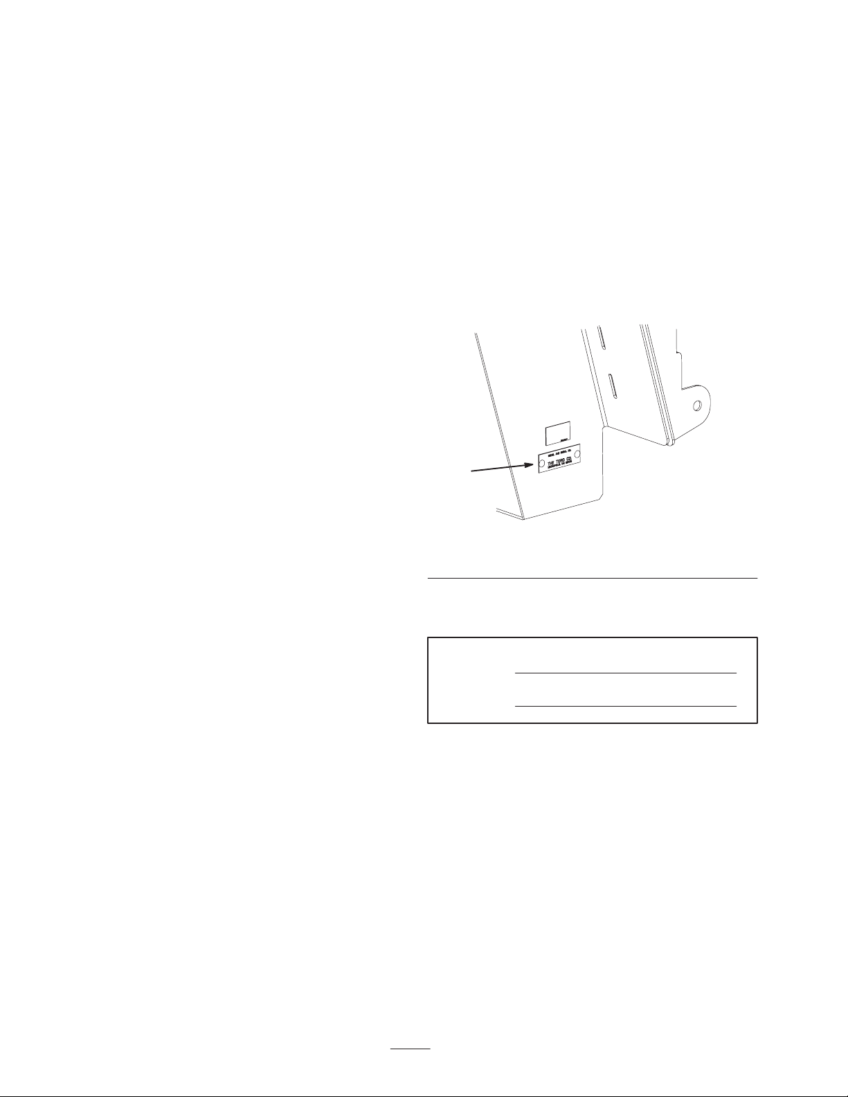
Whenever you need service, genuine Toro parts, or
additional information, contact an Authorized Service
Dealer or Toro Customer Service and have the model and
serial numbers of your product ready. Figure 1 illustrates
the location of the model and serial numbers on the
product.
1
m–60xx
Figure 1
1. Location of the model and serial numbers
Write the product model and serial numbers in the space
below:
Model No.
Serial No.
This manual identifies potential hazards and has special
safety messages that help you and others avoid personal
injury and even death. Danger, Warning, and Caution are
signal words used to identify the level of hazard. However,
regardless of the hazard, be extremely careful.
Danger signals an extreme hazard that will cause serious
injury or death if you do not follow the recommended
precautions.
Warning signals a hazard that may cause serious injury or
death if you do not follow the recommended precautions.
Caution signals a hazard that may cause minor or moderate
injury if you do not follow the recommended precautions.
W 2004 by The Toro Company
8111 Lyndale Avenue South
Bloomington, MN 55420-1196
All Rights Reserved
Printed in the USA
2
This manual uses two other words to highlight information.
Important calls attention to special mechanical
information and Note: emphasizes general information
worthy of special attention.
Safety
The following list contains safety information specific to
Toro products and other safety information you must know.
• Become familiar with the safe operation of the
equipment, with the operator controls, and safety signs.
• Use extra care with grass catchers or other attachments.
These can change the operating characteristics and the
stability of the machine.
• Never operate with the discharge deflector raised or
removed and never altered, unless using a grass catcher
or mulching baffles.
• Keep hands and feet away from moving parts. Do not
make adjustments with the engine running.
• Stop on level ground, disengage drives, set the parking
brake, shut off the engine before leaving the operator’s
position for any reason including emptying the grass
catcher or unclogging the chute.
• If you remove the grass catcher, be sure to install any
discharge deflector or guard that might have been
removed to install the grass catcher. Do not operate the
mower without either the entire grass catcher or the
grass deflector in place.
• Do not use a grass catcher on steep slopes. A heavy
grass catcher could cause loss of control or overturn the
machine.
• Slow down and use extra care on hillsides. Be sure to
travel in the recommended direction on hillsides. Turf
conditions can affect the machine’s stability. Use
extreme caution while operating near drop–offs.
• Keep all movement on slopes slow and gradual. Do not
make sudden changes in speed, directions or turning.
• The grass catcher can obstruct the view to the rear. Use
extra care when operating in reverse.
• Use care when loading or unloading the machine into a
trailer or truck
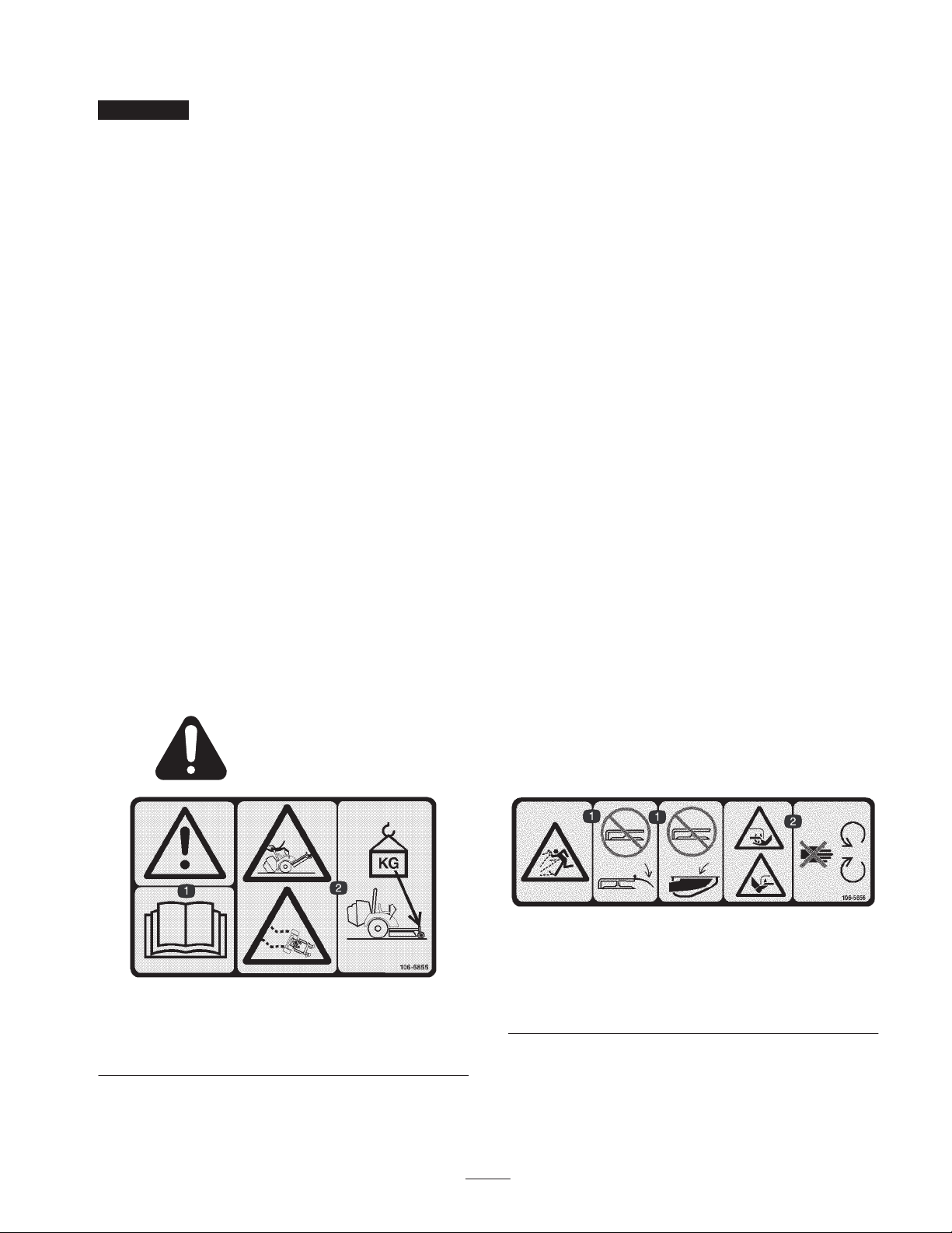
Safety and Instruction Decals
Safety decals and instructions are easily visible to the operator and are located near any area
of potential danger. Replace any decal that is damaged or lost.
• Turn off the engine and wait for all moving parts to
stop before removing the grass catcher or
unclogging the chute.
• Do not use your hands to unclog the chute, blower or
bagger.
• Do not leave grass in grass catcher for extended periods
of time.
• Grass catcher components are subject to wear, damage
and deterioration, which could expose moving parts or
allow objects to be thrown. Frequently check
components and replace with manufacturer’s
recommended parts, when necessary.
• Do not leave grass or debris in grass catcher while
transporting the machine.
106-5855
1. Warning—read the Operator’s Manual.
2. Tipping and lose of control hazard—add weight to the front of
the machine.
106-5856
1. Thrown object hazard—do not operate the mower with the
deflector up or removed; keep the deflector or grass collector in
place.
2. Cutting/dismemberment hazard of hand or foot, mower
blade—stay away from moving parts.
3

107-1613
Setup
Note: Determine the left and right sides of the machine from the normal operating position.
Loose Parts
Note: Use the chart below to verify all parts have been shipped.
Step Description Qty. Use
1
2
3
4
5
16
16
1
1
1
1
1
6
Installing the clutch and drive pulley
assembly
Removing the heat shield on 44 and
48 inch mowers
Removing the heat shields and rear
weight on 52 inch mowers
Installing the bagger mounting bracket
Bolt, 7/16 x 4–1/2 inch—Kawasaki
engines only
Bolt, 7/16 x 4 inch—Kohler® engines
only
Drive pulley assembly
Clutch spacer
No parts needed Removing the drive wheels
No parts needed
No parts needed
Bagger mounting bracket
Bolt, 5/16 x 1 inch
Flange nut, 5/16 inch
Flat washer, 5/16 inch
®
6
7
Idler pulley assembly with bracket
Bolt, 5/16 x 7/8 inch
Flange nut, 5/16 inch
Spring bracket
Shoulder bolt, 3/8 x 2–1/2 inch
Nut, 3/8 inch
Bagger
Clevis pin
Hairpin cotter
1
5
5
1
1
1
1
2
2
4
Installing the bagger idler pulley and
skid plate
Installing the bagger

Step UseQty.Description
8
9
10
11
12
13
Spring
Bagger belt
Spacer 3
Weight plate
U–bolt
Locknut, 3/8 inch
Bolt, 3/8 x 2 inch
Belleville washer
Bar weight
Locknut, 3/8 inch
Bolt, 3/8 x 5–3/4 inch
Belleville washer
Bagger bracket
Carriage bolt, 5/16 x 1 inch
Flange nut, 5/16 inch
Bolt, 1/2 x 1–3/4 inch
Jam nut, 1/2 inch
1
1
4
2
8
4
4
4
2
2
2
1
8
8
1
2
Installing the bagger belt
Checking/adjusting the bagger belt
tension
Installing the weight plates
Installing the bar weights
Installing the boot and discharge tubes
Installing the bagger dump lever stop
bolt
14
15
No parts needed Adjusting the bagger dump lever
No parts needed Checking the tire pressure
5
Step
1
1
2
Parts needed for this step:
• 1 Bolt, 7/16 x 4–1/2 inch—Kawasakir engines only
• 1 Bolt, 7/16 x 4 inch—Kohlerr engines only
• 1 Drive pulley assembly
• 1 Clutch spacer
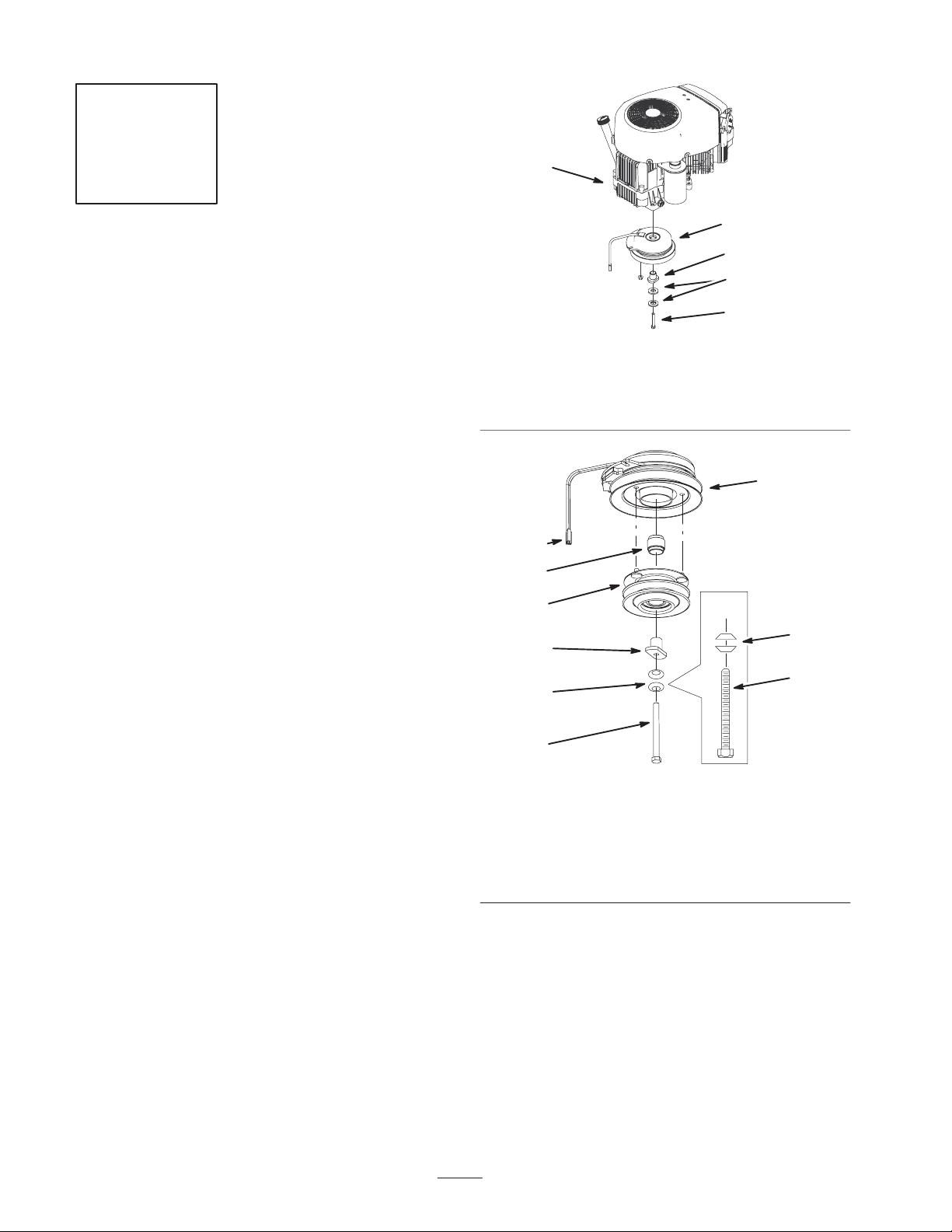
Installing the Clutch and Drive
Pulley Assembly
Note: Apply anti–seize compound to crank shaft before
installing the clutch and drive pulley assembly.
1. If not already removed, remove the existing clutch bolt
from the machine and discard (Fig. 2 and 3).
2. If not already removed, remove the existing drive
spacer from the clutch (Fig. 2 and 3).
3. Install the new pulley spacer into the clutch (Fig. 3).
4. Install the drive pulley assembly into the three holes
drilled into the clutch pulley (Fig. 3).
5. Install the drive spacer into the drive pulley assembly
(Fig. 3).
1. Engine
2. Clutch
3. Curved washers
2
3
4
8
5
Figure 2
5
3
4
4. Clutch bolt—discard
5. Drive spacer
1
5
6 or 7
m–6024
Note: There are two different size bolts for installing the
clutch. The size is determined by the type of engine on the
machine.
6. If the machine has a Kawasaki® engine, then install the
clutch with a bolt (7/16 x 4–1/2 inch) and 2 existing
curved washers (Fig. 3).
7. If the machine has a Kohler® engine, then install the
clutch with a bolt (7/16 x 4 inch) and 2 existing curved
washers (Fig. 3).
8. Torque the clutch bolt to 55 ft–lb (75 Nwm) (Fig. 3).
9. If needed, install the existing deck belt onto the clutch.
10. If needed, install the clutch strap.
11. If needed, plug in the clutch connector (Fig. 3).
6 or 7
1. Clutch
2. Clutch connector
3. Pulley spacer
4. Drive pulley assembly
5. Curved washers
6
m–6007
Figure 3
6. Bolt, 7/16 x 4–1/2 inch for
Kawasaki engines
7. Bolt, 7/16 x 4 inch for
Kohler engines
8. Drive spacer
Step
Step
2
No parts needed for this step.
Removing the Drive Wheels
Danger
Mechanical or hydraulic jacks may fail to support
machine and cause a serious injury.
• Use jack stands when supporting machine.
• Do not use hydraulic jacks.
1. Loosen the drive wheel lugs or nuts.
2. Raise the rear of the machine and support with jack
stands.
3. Remove the drive wheels.
3
No parts needed for this step.
Removing the Rear Heat Shield
on 44 and 48 inch Mowers
1. Remove the 8 bolts and nuts securing the rear of the
heat shield to the engine straps and the rear bumper
(Fig. 4).
2. Remove the 4 bolts, the washers and the nuts securing
the sides of the heat shield to the engine straps, the
tailpipe guard and the bumper (Fig. 4). Save the heat
shield and all the hardware.
3
2
1
1. Heat shield
2. Engine straps
2
4
m–6809
Figure 4
3. Tailpipe guard
4. Frame
7
Step
Step
4
No parts needed for this step.
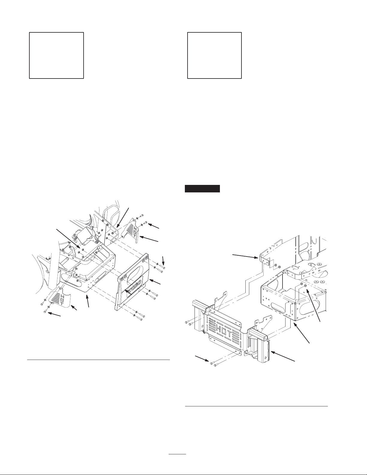
Removing the Rear Weight and
Heat Shields on 52 inch
Mowers
1. Remove the 8 bolts, washers, and nuts securing the rear
weight to the engine straps and the rear bumper (Fig. 4).
2. Remove the 4 bolts, washers and nuts securing the side
heat shields to the engine straps, and the bumper
(Fig. 4). Save the heat shields, the weight and all the
hardware.
2
6
5
1
5
Parts needed for this step:
• 1 Bagger mounting bracket
• 16 Bolts, 5/16 x 1 inch
• 16 Flange nuts, 5/16 inch
• 6 Flat washers, 5/16 inch
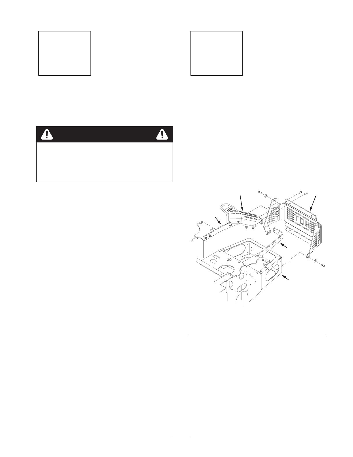
Installing the Bagger Mounting
Bracket
Important Do not tighten any bolts until all bolts are
loosely installed for the bagger mounting bracket.
1. Loosely install the bagger mounting bracket to the back
of the rear bumper and the engine guard straps, with 8
bolts (5/16 x 1 inch) and 8 flange nuts (5/16 inch)
(Fig. 6).
m–7760
1. Heat shield
2. Engine straps
3. Rear weight
5
3
4
4
1
5
Figure 5
4. Rear bumper
5. Bolt
6. Nut
2
1. Bagger mounting bracket
2. Bolt, 5/16 x 1 inch
3. Flange nut, 5/16 inch
5
3
4
1
Figure 6
4. Back of rear bumper
5. Engine guard strap
8
 Loading...