

Page 1

Form No. 3329–565
44 and 52 Finishing Kit
100 Series Z Master 44 Mowers
100 Series Z Master 52 Mowers
Model No. 78508
Model No. 78509
Installation Instructions
Important This kit will require significant time to install the first time. A right angle drill is recommended for
installation.
Loose Parts
Note: Use the chart below to verify all parts have been shipped.
Step Description Qty. Use
1
2
3
4
5
6
Tunnel baffle—front
Carriage bolt, 5/16 x 5/8 inch
Flange nut, 5/16 inch
Tunnel baffle—rear
Carriage bolt, 5/16 x 5/8 inch
Flange nut, 5/16 inch
Center rear baffle
Button Head Socket Bolt, 5/16 x 3/4 inch
Flange nut, 5/16 inch
Left rear baffle
Button Head Socket Bolt, 5/16 x 3/4 inch
Flange nut, 5/16 inch
Right rear baffle
Button Head Socket Bolt, 5/16 x 3/4 inch
Carriage bolt, 5/16 x 5/8 inch
Flange nut, 5/16 inch
1
4
4
1
3
3
1
3
3
1
3
3
1
2
1
3
Installing the front tunnel baffle
Installing the rear tunnel baffle
Installing the center rear baffle
Installing the left rear baffle
Installing the right rear baffle
Removing the mower existing pulley
assembly
7
Pulley assembly
8
9
2003 by The Toro Company
8111 Lyndale Avenue South
Bloomington, MN 55420-1196
Bagger Belt
Pulley cover
Mounting plate
Bolt, 3/8 x 1–1/4 inch
Flange nuts, 3/8 inch
Modifying a 44 inch Mower for Belt
Clearance
1
1
1
2
4
4
1
Installing the pulley assembly, belt and
cover
Installing the mounting plate
All Rights Reserved
Printed in the USA
Page 2
Before Installation
Checking the Mower for
Existing Holes
Check for existing holes. Use existing holes in the mower
that align the baffles in their correct positions.
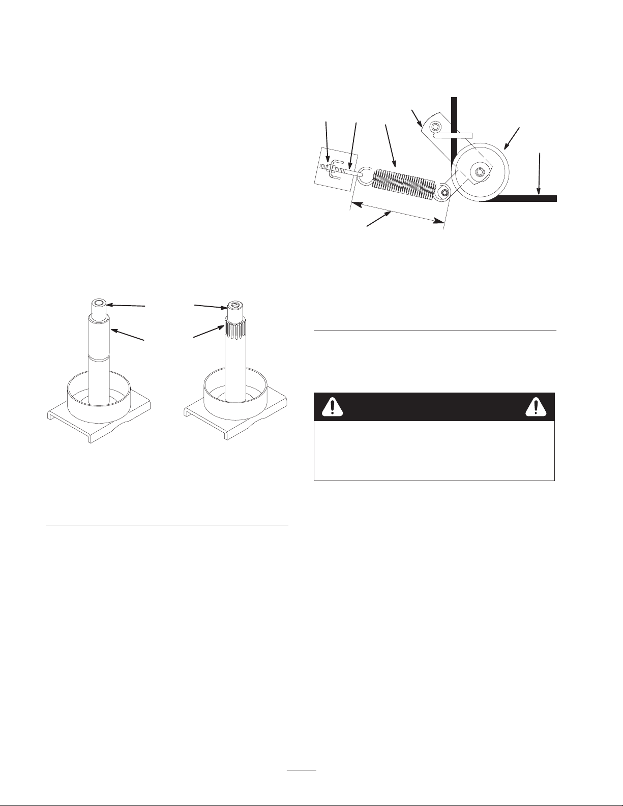
Checking the Spindle Shaft for
1999 Models
For mowers built in 1999, the right hand blade spindle
shaft may need to be replaced (Fig. 1). Check the right
blade spindle for splines. The splines are needed to install
the pulley assembly shown in Figure 17.
Order a new, year 2000 model, splined spindle shaft from
an Authorized Service Dealer (Fig. 1).
1
2
3
4
14
6
1. Outer nut
2. Idler pulley
3. Idler arm
4. Spring eye bolt
2. Remove the mower belt, starting at the right outside
pulley.
Note: Do not remove the spring.
3
5
Figure 2
Top View
5. Spring
6. 9–3/8 inch ± 1/8 inch
(238 mm ±3 mm)
7. Mower belt
2
M–4197
7
m–6381
Figure 1
Top View
1. Blade spi n d l e
shaft—without splines
2. No splines
3. Year 2000 blade spindle
shaft—with splines
4. Splines
Removing the Mower
Note: If the mower is already level and is removed from
the top bolts, the mower will not need to be leveled.
1. Loosen the outer nut on the spring eye bolt (Fig. 2).
Caution
Spring is under tension when installed and can
cause personal injury.
Do not remove spring from spring eye bolt.
3. Lower the mower onto wood blocks.
Note: If the mower is removed from the top bolts, the
mower will not need to be leveled.
4. Remove the four bolts and nuts at the top of chains
that attached to mower (Fig. 3).
5. Remove the nuts and bolts holding the push arm pins
(Fig. 3).
Note: The gage wheels may need to be removed to allow
the push arm pins to be removed (Fig. 3).
6. Remove the push arm pins (Fig. 3).
2
Page 3
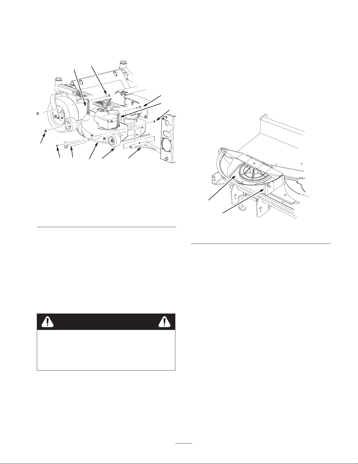
7. Raise the height of cut lever and slide the mower out
(Fig. 3).
Removing the Cutting
Chamber Stiffener
9
5
m–6062
1. Mower
2. Chain
3. Chain Bolt
4. Push Arm
5. Push Arm Bolt
3
2
welded to the cutting chamber (Fig. 4).
1. Remove the cutting chamber stiffener from the mower
(Fig. 4).
Note: This section is only for mowers with a stiffener
3
2
6
7
8
1
4
m–6265
2. Grind the welds flat on rear part of the chamber. This
will allow the correct fit for the cutting chamber
baffle.
Figure 3
6. Push Arm Nut
7. Push Arm Pin
8. Gage wheel
9. Nut
1
2
m–6684
Figure 4
1. Cutting chamber 2. Cutting chamber stiffener
Preparing the Mower
1. Tip the mower upside down and block up ends to ease
installation of components.
2. Thoroughly clean the mower. All debris must be
removed to ensure baffles will fit properly against the
mower.
3. Repair all bent or damaged areas of the mower and
replace any missing parts.
Warning
Contact with sharp blade can cause serious
personal injury.
• Wear gloves or wrap sharp edges of the blade
with a rag.
3
Page 4
Step
5. Remove the clamp.
6. Install the front tunnel baffle to the mower with
4 carriage bolts (5/16 x 5/8 inch) and 4 flange nuts
(5/16 inch) (Fig. 6).
1
Parts needed for this step:
• 1 Tunnel baffle—front
• 4 Carriage bolts, 5/16 x 5/8 inch
• 4 Flange nuts, 5/16 inch
Installing the Front Tunnel
Baffle
Note: Blades and spindles are not shown in the graphics
for clarity.
1. Place the front tunnel baffle against the front wall of
the discharge tunnel (Fig. 5).
2. Align the front baffle, flush with the outside of the
mounting bracket (Fig. 5).
1
3
2
1
3
m–6708
1. Front tunnel baffle
2. Carriage Bolt, 5/16 x
5/8 inch
34
2
Figure 6
3. Flange nut, 5/16 inch
4. Front tunnel wall
2
m–6707
Figure 5
1. Front tunnel baffle
2. Flush edge with outside of
mounting bracket
3. Clamp the baffle in place.
4. Using the baffle as a template, center punch and drill
4 holes (11/32 inch dia.) into the mower (Fig. 5).
3. Outside of mounting
bracket
4. Hole to drill
4
4
Page 5
Step
4. Using the baffle as a template, center punch and drill
3 holes (11/32 inch dia.) into the top of the mower
(Fig. 6).
5. Remove the clamp.
2
Parts needed for this step:
• 1 Tunnel baffle—rear
• 3 Carriage bolt, 5/16 x 5/8 inch
• 3 Flange nut, 5/16 inch
Installing the Rear Tunnel
Baffle
Note: Blades and spindles are not shown in the graphics
for clarity.
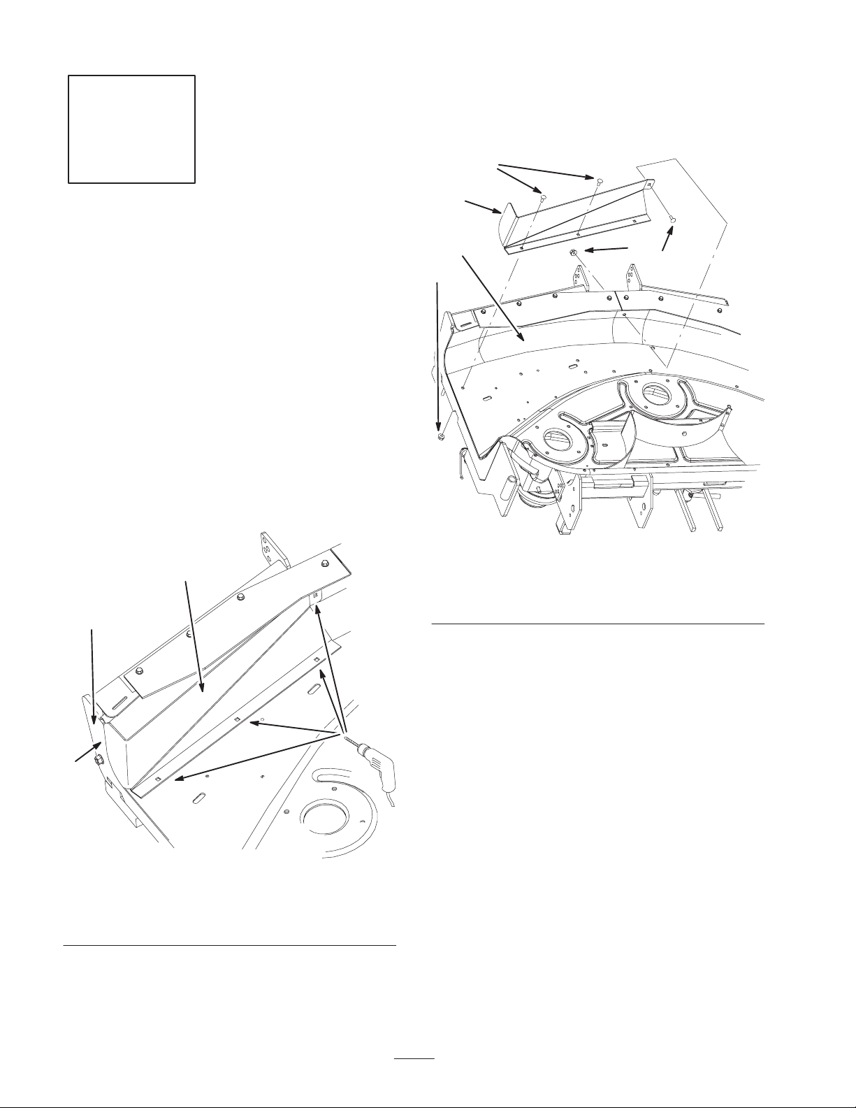
1. Place the rear tunnel baffle against the rear wall of the
discharge tunnel (Fig. 7).
Note: The rear tunnel baffle must not extend past the
outside of the mounting bracket.
2. Align the rear tunnel baffle, flush with the outside of
the mounting bracket (Fig. 7).
6. Install the rear tunnel baffle with 3 carriage bolts
(5/16 x 5/8 inch) and 3 flange nuts (5/16 inch) (Fig. 8).
Important Make sure the bolt heads are installed on
the inside of the cutting chamber.
2
4
4
1
6
5
4
3
1
3
4
m–6709
1. Rear tunnel baffle
2. Mounting bracket
3. Flush edge with outside of
mounting bracket
2
Figure 7
4. Outside of mounting
bracket
1. Rear tunnel baffle
2. Carriage Bolt, 5/16 x
5/8 inch
3. Flange nut, 5/16 inch
m–6710
Figure 8
4. Hole to drill
5. Tunnel rear wall
6. Mounting bracket
3. Clamp the baffle in place.
5
Page 6

Step
3
Parts needed for this step:
• 1 Center cutting chamber baffle
• 3 Button Head Socket Bolts, 5/16 x 3/4 inch
• 3 Flange nuts, 5/16 inch
4 32
Figure 10
1. Baffle flange
2. Blade
3. Spindle
4. Clamp the center baffle tightly against the cutting
chamber (Fig. 11).
4. Blade clearance,
9/16 to 11/16 inch
(14 mm to 17 mm)
m–62291
Installing the Center Rear
Baffle
A right angle drill is recommended to install this baffle.
1. Place the center rear baffle behind the center cutting
blade chamber (Fig. 11).
2. Align the center rear baffle so the baffle ends are
touching the back mower flange (Fig. 9).
Note: The center baffle ends will rest on the mower flange
(Fig. 9).
3. Align the middle part, of the center rear baffle, 9/16 to
11/16 inch from the blade tip. See Figures 9 and 10
on where to measure.
5
4
5. Using the baffle as a template, mark, center punch and
drill 1/8 inch pilot holes at the 3 locations (Fig. 11).
6. Drill 11/32 inch dia. holes through the pilot holes
(Fig. 11).
7. Install the center baffle with 3 button head socket bolts
(5/16 x 5/8 inch) and 3 flange nuts (5/16 inch)
(Fig. 11).
Important Make sure the bolt heads are installed on
the inside of the cutting chamber (Fig. 11).
53
1
4
5
2
3
Figure 9
1. Mower flange
2. Center baffle
3. Center baffle end touching
mower
Important Make sure the baffle flange is
9/16 to 11/16 inch (14 mm to 17 mm) from the mower
blade (Figures 9 and 10).
4. Blade clearance,
9/16 to 11/16 inch
(14 mm to 17 mm)
5. Center blade
m–6256
1
2
2
m–6176
Figure 11
1. Center Baffle
2. Hole to drill
3. Center cutting blade
chamber
6
4. Flange nuts, 5/16 inch
5. Button head socket bolt,
5/16 x 5/8 inch
Page 7

Step
4
Parts needed for this step:
6. Install the left rear baffle with 3 button head socket
bolts (5/16 x 3/4 inch) and 3 flange nuts (5/16 inch)
(Fig. 13).
Important Make sure the bolt heads are installed on
the inside of the cutting chamber. See figure 13.
6
2
• 1 Left rear baffle
• 3 Button Head Socket Bolts, 5/16 x 3/4 inch
• 3 Flange nuts, 5/16 inch
Installing the Left Rear Baffle
Note: Blades and spindles are not shown in the graphics
for clarity.
1. Place the left rear baffle behind the left cutting
chamber (trim side of mower) (Fig. 12). The tabs will
mount on the outside of the mower.
2. Align the left rear baffle tight against and flush with
the bottom of the center baffle and against the mower
flange (Figures 12 and 13).
3. Clamp the baffle in place.
5
1
8
4
1. Left rear baffle
2. Left side of mower
3. Button head socket bolt,
5/16 x 3/4 inch
4. Flange nut, 5/16 inch
3
7
5
m–6179
Figure 13
5. Hole to drill
6. Rear center baffle
7. Mower flange
8. Tab
6
4
1
3
Figure 12
1. Center Baffle
2. Left rear baffle against
mower flange
3. Flush with bottom of
center baffle
4. Using the baffle as a template, mark, center punch and
drill 1/8 inch pilot holes at the 3 locations (Fig. 13).
5. Drill 11/32 inch dia. holes through the pilot holes
(Fig. 13).
2
5
4. Left cutting chamber
5. Tab
6. Trim side of mower
m–6178
7
Page 8

Step
5
Parts needed for this step:
• 1 Right rear baffle
• 2 Button Head Socket Bolts, 5/16 x 3/4 inch
• 1 Carriage bolts, 5/16 x 5/8 inch
• 4 Flange nuts, 5/16 inch
Installing the Right Rear Baffle
3. Clamp the baffle in place.
4. Using the baffle as a template, mark, center punch and
drill 1/8 inch pilot holes at the 2 locations (Fig. 15).
5. Drill 11/32 inch dia. holes through the pilot holes
(Fig. 15).
6. Remove the clamp.
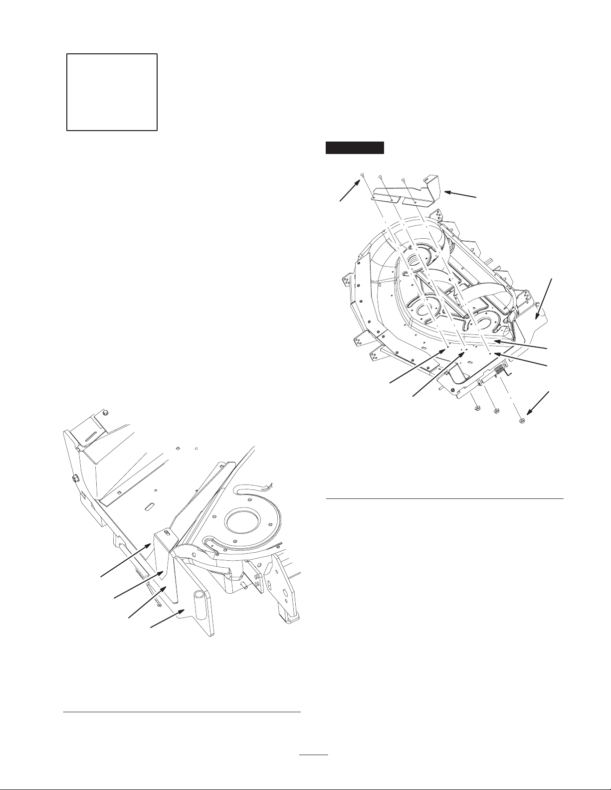
7. Install the right rear baffle to the mower with 2 button
head socket bolts (5/16 x 3/4 inch) and 2 flange nuts
(5/16 inch) (Fig. 15).
8. Install the right rear baffle to the rear tunnel baffle
with a carriage bolt (5/16 x 5/8 inch) and a flange nut
(5/16 inch) (Fig. 15).
Important Make sure the button head socket bolt
heads are installed on the inside of the cutting chamber.
See figure 15.
Note: Blades and spindles are not shown in the graphics
for clarity.
1. Place the right rear baffle (side discharge side) behind
the right cutting chamber (Fig. 14). The tabs will
mount on the outside of the mower.
2. Align the right rear baffle tight against and flush with
the bottom of the center baffle and against the mower
flange (Fig. 14 and 15).
4
1
5
2
6
3
m–6712
1. Right rear baffle
2. Right side of mower
3. Carriage Bolt, 5/16 x
5/8 inch
4. Button head socket bolt,
5/16 x 5/8 inch
5
Figure 15
5. Flange nut, 5/16 inch
6. Holes to drill
7. Mower flange
5
4
4
7
15
1. Center Baffle
2. Right rear baffle against
mower flange
3. Flush with bottom of
center baffle
2
Figure 14
4. Right cutting chamber
5. Side discharge opening
3
m–6711
9. Rotate the blades and check if the blades make contact
with the baffles.
10.If contact is made, do not use the mower. Adjust and
make sure all baffles are installed properly.
8
Page 9

Step
2
3
5
6
No Parts needed for this step.
Removing the Existing Mower
Pulley
Note: Clean the area around pulley before removing
pulley assembly. Hold spindle up from underneath the
deck. It can fall when nut and washer are removed.
1. Turn the mower over.
2. Remove the right belt cover from the mower and
discard.
3. Remove the nut and washer on top of the spindle
(Fig. 17). Save the nut and washer.
4. Remove the existing pulley assembly.
Step
1
1. 44 inch mower
2. Remove this corner
3. 3–1/4 inches
4
4
m–6713
Figure 16
4. 1 inch
5. Pulley cover stud
7
No Parts needed for this step.
Modifying a 44 inch Mower for
Belt Clearance
Note: This section is only for 44 inch mowers that do not
have a belt clearance notch.
1. Remove the right rear corner of the pulley cover plate
(Fig. 16). This will give clearance for the blower belt.
2. Refer to Figure 16 for the correct dimensions of the
cutout.
Note: Do not cut out the stud in the back of the pulley
cover plate. The stud is needed for the pulley cover.
9
Page 10

Step
8
Parts needed for this step:
• 1 Pulley assembly
• 1 Bagger Belt
• 1 Pulley cover
Installing the Pulley Assembly
Note: For mowers built in 1999, check the right blade
spindle for splines. Refer to Checking the Spindle for
1999 Models on page 2.
1. Install new pulley assembly onto the spindle. Install it
so the large pulley is on the bottom (Fig. 17).
2. Install the washer and nut (Fig. 17).
Installing the Belt Cover and Bagger Belt
Refer to the bagger Operator ’s Manual for installing the
belt cover and bagger belt.
Important Tighten the nut to 115 ft–lb ± 15 ft–lb
torque.
3. Grease the spindle to fill bearings with grease.
1
2
3
4
5
Figure 17
1. Nut
2. Washer
3. Pulley Assembly
4. Blade spindle
5. Mower
6. Lower pulley
7. Upper pulley
7
6
m–6714
10
Page 11

Step
9
Parts needed for this step:
• 2 Mounting plates
• 1 Template
• 4 Bolts, 3/8 x 1–1/4 inch
• 4 Flange nuts, 3/8 inch
Installing the Mounting Plates
Drilling the Holes into the Mounting
Bracket
This kit contains a metal template for locating the
mounting bracket holes to drill.
Installing the Mounting Plates
1. Install the mounting plates to the inside of the
mounting bracket with 4 bolts (3/8 x 1–1/4 inch) and
4 flange nuts (3/8 inch) (Fig. 19).
1
1
5
2
4
3
m–6683
1. Remove the grass deflector from the mower (Fig. 22).
2. Position the template onto the the mounting bracket
and align with the top and sides of the mounting
bracket. (Fig. 18).
3. Clamp the template to the mounting bracket (Fig. 18).
4. Mark and center punch the 4 holes and remove the
template (Fig. 18).
5. Drill 1/8 inch pilot holes at the 4 marked locations and
then drill 7/16 inch dia. holes.
6. File the metal burrs from the drilled holes.
3
1
3
1. Template
2. Mounting bracket
Figure 18
3. Mark and center punch
holes
m–6225
2
1. Mounting plate
2. Bolt, 3/8 x 1–1/4 inch
3. Flange nut, 3/8 inch
Figure 19
4. Mounting bracket
5. 7/16 inch holes to drill
11
Page 12

Installing the Blades
Installing the Mower and
Note: In certain mowing conditions, improved bagging
performance can be achieved by using bagging blades.
Contact an Authorized Service Dealer for the proper
blades for different mowing conditions.
1. Install the blade onto the spindle shaft (Fig. 20).
Important The curved part of the blade must be
pointing upward toward the inside of the mower to ensure
proper cutting.
2. Install the spring disk and blade bolt (Fig. 20). Torque
the blade bolt to 85–110 ft-lb (115–150 Nm).
3. Rotate the blades to ensure there is clearance between
the blade tips and the baffles.
4. If contact is made, do not use the mower. Adjust and
make sure the baffles are installed properly.
Important Do not use the mower if blades contact the
baffles.
3
5
4
2
Mower Belt
1. Install the mower to the machine. Reverse the
instructions in Removing the Mower on page 2.
Note: If the mower was already level and was removed
from the top bolts, the mower will not need to be leveled.
Refer to the mower Operator ’s Manual if the mower
needs to be leveled.
2. Route the mower belt onto the lower pulley (Fig. 17)
and idler pulley (Fig. 21).
3. Route the mower belt. Refer to the mower Operator ’s
Manual.
4. Tighten the outer nut on spring eye bolt (Fig. 21).
Note: Check the spring length. The spring should measure
9–3/8 inch ± 1/8 inch (238 mm ± 3 mm) when installed.
Adjust if it does not (Fig. 21).
5. Tighten the inner nut on spring eye bolt (Fig. 21).
14
3
5
2
7
1
4
1. Sail Area of Blade
2. Blade
3. Spring Disk
Figure 20
4. Blade Bolt
5. Cone T owards Bolt Head
3
M–4226
6
M–4197
Figure 21
Top View
1. Outer nut
2. Idler pulley
3. Idler arm
4. Spring eye bolt
5. Spring
6. 9–3/8 inch ± 1/8 inch
(238 mm ±3 mm)
7. Mower belt
12
Page 13

Using the Grass Deflector
Installing the Grass Deflector
Important Make sure the grass deflector is installed
when the bagger and tubes are removed.
Warning
Without the grass deflector, bagger tubes or
complete bagger assembly mounted in place, you
and others are exposed to blade contact and
thrown debris. Contact with the rotating mower
blade(s) and thrown debris will cause injury or
death.
• Always install the grass deflector when
removing the bagger and changing to side
discharge mode.
• If the grass deflector is ever damaged, replace
it immediately. The grass deflector routes
material down toward the turf.
• Never put your hands or feet under the mower.
• Never try to clear the discharge area or mower
blades unless you move the power take off
(PTO) to off and rotate the ignition key to off.
Also remove the key and pull the wire off of the
spark plug(s).
1. When the bagger is to be used for dedicated bagging,
leave the grass deflector off the machine.
• Remember to install the grass deflector when
changing to side discharge mode.
2. When the mower is switched between bagging and
side discharge frequently, leave the grass deflector on
the machine. The grass deflector will rest against the
blower belt cover.
Important Make sure the grass deflector is installed
when the bagger and tubes are removed.
The grass deflector spring will have either an L end or a
straight end (Fig. 22).
Warning
An uncovered discharge opening could allow the
lawn mower to throw objects in the operator’s or
bystander’s direction and result in serious injury.
Also, contact with the blade could occur.
Never operate the lawn mower unless you install a
cover plate, a mulch plate, grass deflector or a
grass chute and catcher.
1. Place spacer and spring onto grass deflector. Place the
L or the straight end of spring behind deck edge.
Note: Make sure the L or the straight end of spring is
installed behind deck edge before installing the bolt as
shown in figure 22.
2. Install bolt and nut. Place J hook end of spring around
grass deflector (Fig. 22).
Important The grass deflector must be lowered down
into position. Lift the deflector up to test that it lowers
into the full down position.
8
6
1
4
2
3
5
10
1. Bolt
2. Spacer
3. Locknut
4. Spring
5. Spring installed
6. Grass Deflector
13
7
m–6085
Figure 22
7. L end of spring, place
behind mounting bracket
before installing bolt
8. J hook end of spring
9. Mounting bracket
10. Straight end—possible
style of spring
Page 14

141516
Page 15

Page 16

 Loading...