

Page 1

Form No. 3353–631 Rev A
44I, 48Iand 52I Twin Soft Bagger
Z100 and Z400 Series Z Master
Model No. 78507—Serial No. 250000351 and Up
Operator’s Manual
Register your product at www.Toro.com
Original Instructions (EN)
Page 2
Contents
Introduction
Introduction 2. . . . . . . . . . . . . . . . . . . . . . . . . . . . . . . . .
Safety 3. . . . . . . . . . . . . . . . . . . . . . . . . . . . . . . . . . . . . .
Safety and Instruction Decals 4. . . . . . . . . . . . . . . . .
Setup 5. . . . . . . . . . . . . . . . . . . . . . . . . . . . . . . . . . . . . .
Loose Parts 5. . . . . . . . . . . . . . . . . . . . . . . . . . . . . . .
Before Installation 6. . . . . . . . . . . . . . . . . . . . . . . . . . . .
Prepare the Mower 6. . . . . . . . . . . . . . . . . . . . . . . . .
Positioning the Flow Baffle (Z400 Mowers only) 6.
Installing the Bagger Bracket (All Z100 Mowers and
Z400 Mowers with 44in and 48in Mower Decks) 6
Installing the Bagger Bracket
(Z400 Mowers with 52in Mower Decks) 9. . . . . . . .
Installing the Blower Assembly 10. . . . . . . . . . . . . . .
Installing the Bagger Belt and Idler Spring 11. . . . . .
Installing the Hood Assembly and Bags 13. . . . . . . .
Installing the Bagger Tube 15. . . . . . . . . . . . . . . . . . .
Checking the Tire Pressure 16. . . . . . . . . . . . . . . . . .
Operation 17. . . . . . . . . . . . . . . . . . . . . . . . . . . . . . . . . . .
Positioning the Flow Baffle (Z400 Mowers only) 17.
Emptying the Grass Bags 17. . . . . . . . . . . . . . . . . . . .
Clearing Obstructions From the Bagger System 18. .
Removing the Bagger 18. . . . . . . . . . . . . . . . . . . . . . .
Using the Grass Deflector 19. . . . . . . . . . . . . . . . . . .
Transporting Machines 19. . . . . . . . . . . . . . . . . . . . . .
Operating and Bagging Tips 19. . . . . . . . . . . . . . . . .
Maintenance 21. . . . . . . . . . . . . . . . . . . . . . . . . . . . . . . . .
Recommended Maintenance Schedule 21. . . . . . . . .
Cleaning the Hood Screen 21. . . . . . . . . . . . . . . . . . .
Cleaning the Bagger 21. . . . . . . . . . . . . . . . . . . . . . . .
Checking and Adjusting the Bagger Belt Tension 22.
Checking and Adjusting the Blower Latch 22. . . . . .
Replacing the Blower Belt 23. . . . . . . . . . . . . . . . . . .
Greasing the Idler Arm 24. . . . . . . . . . . . . . . . . . . . .
Checking the Blower Liner 24. . . . . . . . . . . . . . . . . .
Replacing the Blower Liner 24. . . . . . . . . . . . . . . . . .
Inspecting the Bagger 24. . . . . . . . . . . . . . . . . . . . . . .
Inspecting the Mower Blades and Baffles 25. . . . . . .
Installing Mower Blades 25. . . . . . . . . . . . . . . . . . . .
Installing the Grass Deflector 25. . . . . . . . . . . . . . . . .
Storage 25. . . . . . . . . . . . . . . . . . . . . . . . . . . . . . . . . .
Troubleshooting 26. . . . . . . . . . . . . . . . . . . . . . . . . . . . . .
The Toro Total Coverage Guarantee 28. . . . . . . . . . . . . .
Page
Read this manual carefully to learn how to operate and
maintain your product properly. The information in this
manual can help you and others avoid injury and product
damage. Although Toro designs and produces safe
products, you are responsible for operating the product
properly and safely.
You may contact Toro directly at www.Toro.com for
product and accessory information, help finding a dealer, or
to register your product.
Whenever you need service, genuine Toro parts, or
additional information, contact an Authorized Service
Dealer or Toro Customer Service and have the model and
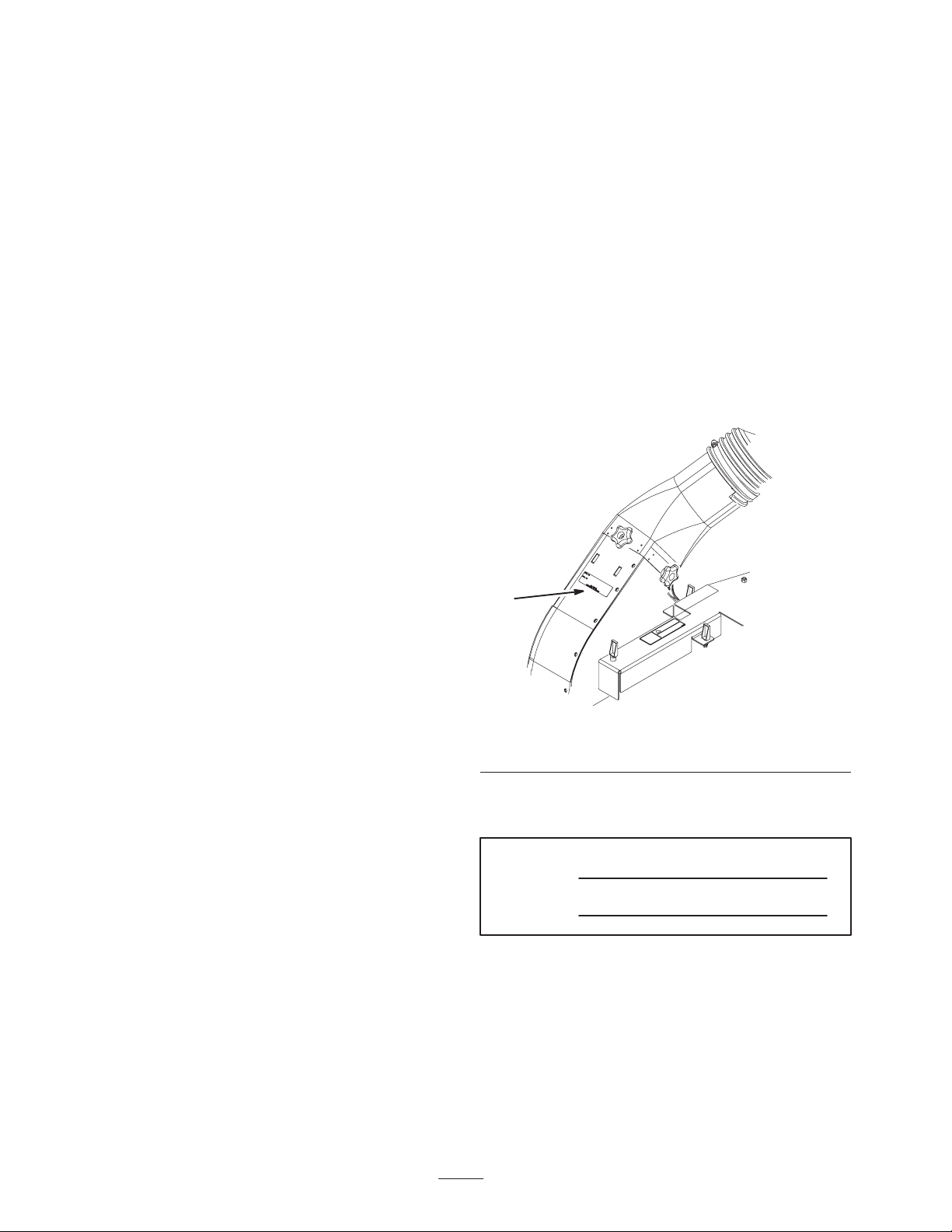
serial numbers of your product ready. Figure 1 illustrates
the location of the model and serial numbers on the
product.
1
m–6231
Figure 1
1. Location of the model and serial numbers
Write the product model and serial numbers in the space
below:
Model No.
Serial No.
This manual identifies potential hazards and has special
safety messages that help you and others avoid personal
injury and even death. Danger, Warning, and Caution are
signal words used to identify the level of hazard. However,
regardless of the hazard, be extremely careful.
W 2005 by The Toro Company
8111 Lyndale Avenue South
Bloomington, MN 55420-1196
Danger signals an extreme hazard that will cause serious
injury or death if you do not follow the recommended
precautions.
Contact us at www.Toro.com
All Rights Reserved
2
Printed in the USA
Page 3

Warning signals a hazard that may cause serious injury or
death if you do not follow the recommended precautions.
Safety
Caution signals a hazard that may cause minor or moderate
injury if you do not follow the recommended precautions.
This manual uses two other words to highlight information.
Important calls attention to special mechanical
information and Note: emphasizes general information
worthy of special attention.
The following list contains safety information specific to
Toro products and other safety information you must know.
• Become familiar with the safe operation of the
equipment, with the operator controls, and safety signs.
• Use extra care with grass catchers or other attachments.
These can change the operating characteristics and the
stability of the machine.
• Do not use a grass catcher on steep slopes. A heavy
grass catcher could cause loss of control or overturn the
machine.
• Slow down and use extra care on hillsides. Be sure to
travel in the recommended direction on hillsides. Turf
conditions can affect the machine’s stability. Use
extreme caution while operating near drop–offs.
• Keep all movement on slopes slow and gradual. Do not
make sudden changes in speed, directions or turning.
• The grass catcher can obstruct the view to the rear. Use
extra care when operating in reverse.
• Use care when loading or unloading the machine into a
trailer or truck
• Never operate with the discharge deflector raised or
removed and never altered, unless using a grass catcher
or mulching baffles.
• Keep hands and feet away from moving parts. Do not
make adjustments with the engine running.
• Stop on level ground, disengage drives, set the parking
brake, shut off the engine before leaving the operator’s
position for any reason including emptying the grass
catcher or unclogging the chute.
• If you remove the grass catcher, be sure to install any
discharge deflector or guard that might have been
removed to install the grass catcher. Do not operate the
mower without either the entire grass catcher or the
grass deflector in place.
• Turn off the engine and wait for all moving parts to
stop before removing the grass catcher or
unclogging the chute.
• Do not use your hands to unclog the chute, blower or
bagger.
• Do not leave grass in grass catcher for extended periods
of time.
• Grass catcher components are subject to wear, damage
and deterioration, which could expose moving parts or
allow objects to be thrown. Frequently check
components and replace with manufacturer’s
recommended parts, when necessary.
• Do not leave grass or debris in grass catcher while
transporting the machine.
3
Page 4
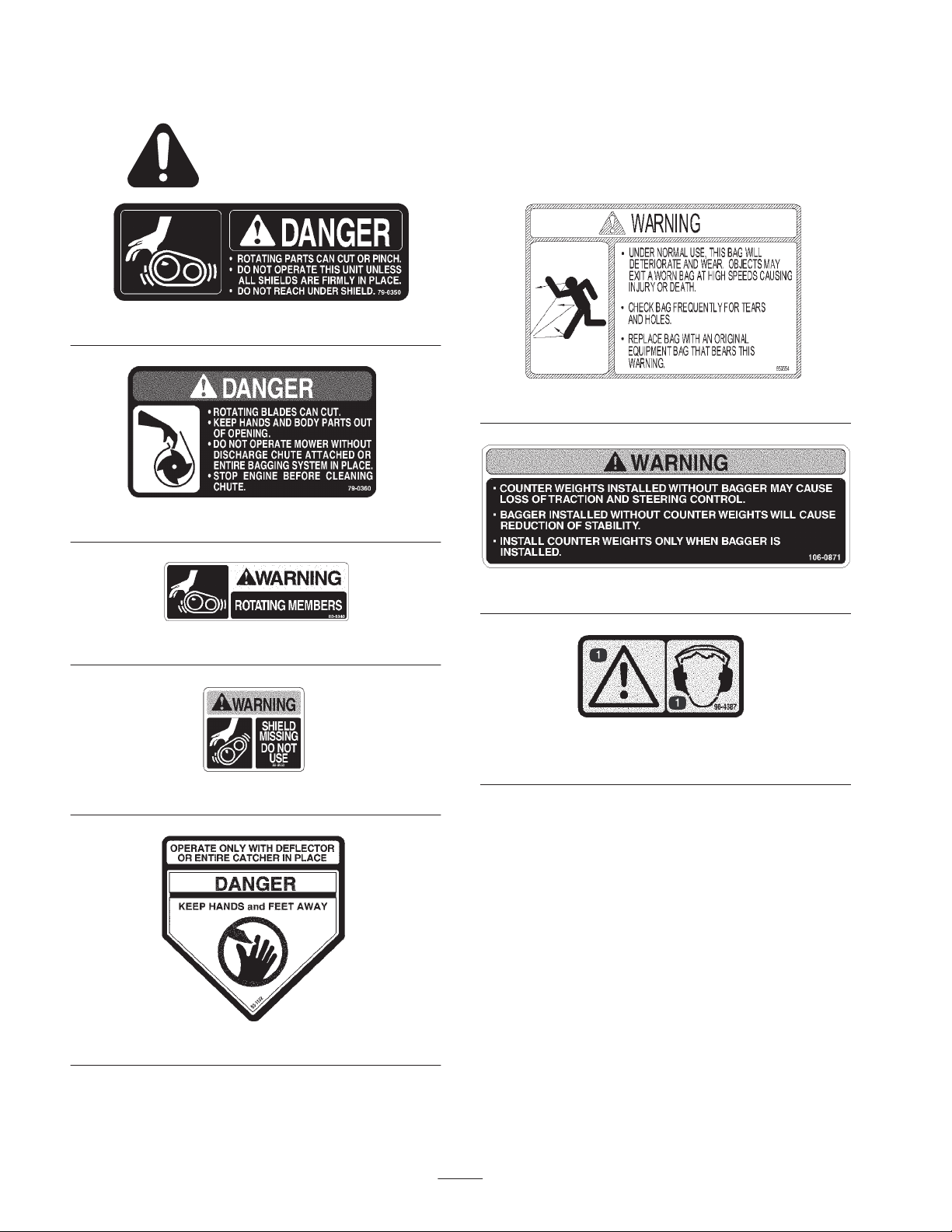
Safety and Instruction Decals
Safety decals and instructions are easily visible to the operator and are located near any area
of potential danger. Replace any decal that is damaged or lost.
79-0350
79-0360
1-653554
80-8040
88-8950
106-0871
98-4387
1. Warning—wear hearing protection.
93-1122
4
Page 5

Setup
Note: Determine the left and right sides of the machine from the normal operating position.
Loose Parts
Note: Use the chart below to verify all parts have been shipped.
Step Description Qty. Use
1
2
3
4
5
6
Bagger bracket
Bolt, 5/16 x 1 inch
Flange nut, 5/16 inch
Bagger bracket 1
Blower assembly 1 Installing the blower assembly
Blower belt cover
Idler spring
Bagger belt
Hood assembly
Bag
Clevis pin
Hairpin cotter
Bagger tube
Clamp
Knob
Blower adapter
1
8
8
1
1
1
1
2
2
2
1
1
2
1
Installing bagger bracket (All Z100
Mowers and Z400 Mowers with 44in and
48in Mower Decks)
Installing bagger bracket (Z400 Mowers
with 52in Mower Decks)
Installing the bagger belt and idler spring
Installing the hood assembly and bags
Installing the bagger tube
7
Important Bagger model 78507 MUST be paired with either model 78508, 78509, 78511, or 78512 finishing kit. Failure
to match the appropriate finishing kit with the appropriate bagger will result in misalignment of the blower assembly relative
to the deck, as well as misalignment of the latch components, and potential interference between the blower inlet shelf and
the deck baffles.
No parts needed – Checking the tire pressure
5
Page 6
Before Installation
Prepare the Mower
Step
Perform the following procedure to prepare the mower for
attaching the blower and finishing kit.
1. Disengage the PTO, move the motion control levers to
the neutral locked position and set the parking brake.
2. Stop the engine, remove the key, and wait for all
moving parts to stop before leaving the operating
position.
3. Clean the mower of any debris on the deck or rear of
mower to ease installation.
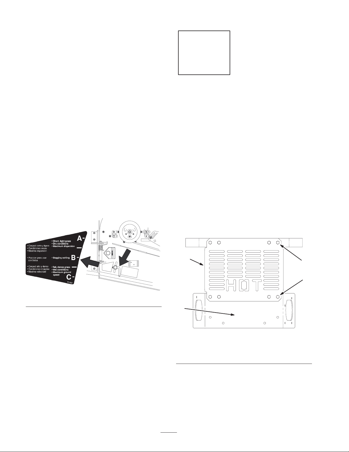
Positioning the Flow Baffle
(Z400 Mowers only)
The middle position or Position B is recommended for
bagging.
Move the adjustable flow baffle to the middle position. To
adjust the baffle refer to your mower Operator’s Manual.
Position B
Middle Position
1
Parts needed for this step:
• 1 Bagger bracket
• 8 Bolts, 5/16 x 1 inch
• 8 Flange nuts, 5/16 inch
Installing the Bagger Bracket
(All Z100 Mowers and Z400
Mowers with 44in and 48in
Mower Decks)
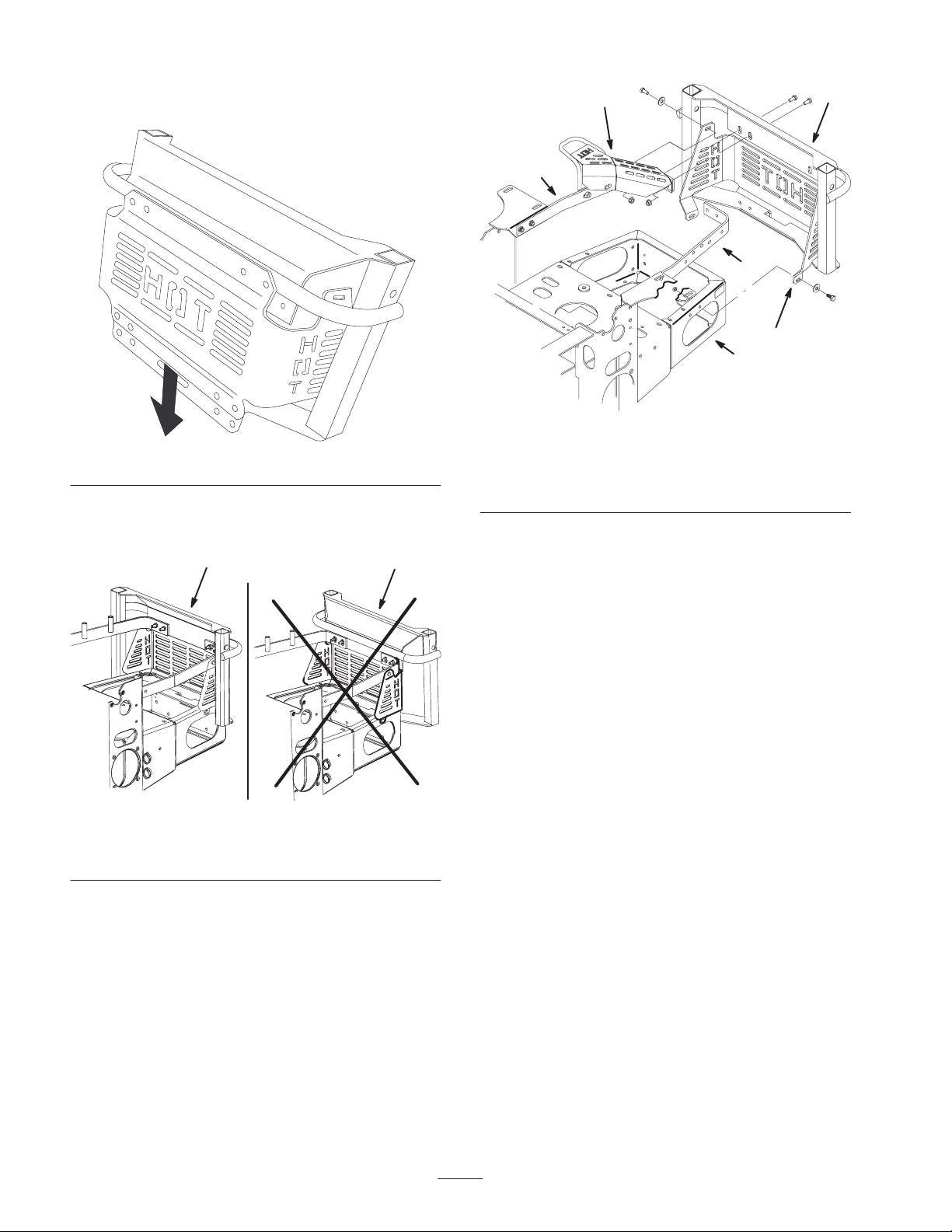
Note: Determine if machine is equipped with a back mount
or back and side mount heat shield. If machine is equipped
with a back mount heat shield (Fig. 4), use steps 1 thru 3. If
machine has a back and side mount heat shield (Fig. 5),
proceed to step 4.
1. Remove the rear heat shield (Fig. 3). Discard the bolts
and nuts.
Figure 2
m–6880
1
3
m–5836
Figure 3
1. Rear heat shield
2. Bolts—remove and
discard
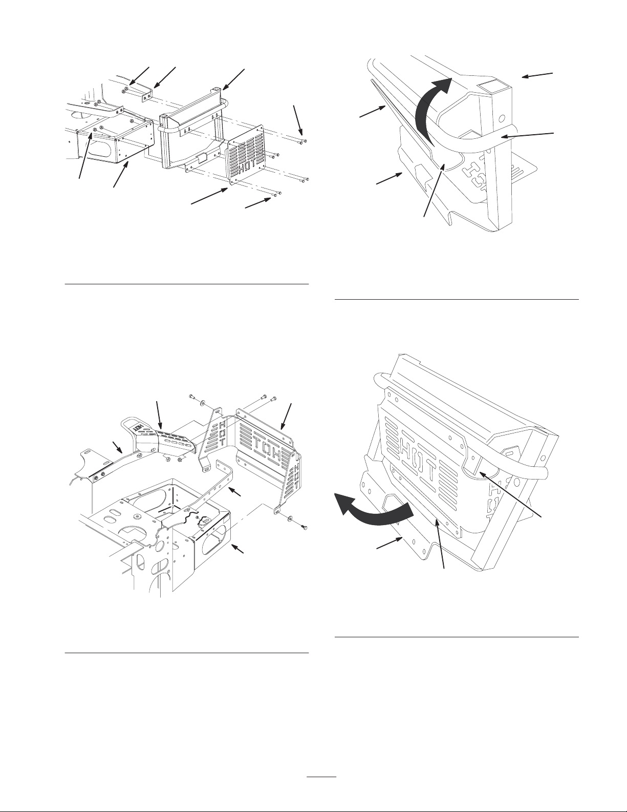
2. Position the bagger bracket behind the engine guard
straps and rear bumper (Fig. 4).
3. Install the bagger bracket and rear heat shield to the
engine guard straps and rear bumper with 8 bolts
(5/16 x 1 inch) and 8 flange nuts (5/16 inch) (Fig. 4).
3. Rear bumper
2
2
6
Page 7
3
5
1
5
2
1
3
3
4
6
2
m–6221
Figure 4
1. Bagger bracket
2. Bolt, 5/16 x 1 inch
3. Flange nut, 5/16 inch
4. Rear bumper
5. Engine guard strap
6. Rear heat shield
4. Remove the 8 bolts and nuts securing the rear of the
heat shield to the engine straps and rear bumper
(Fig. 5). Discard the bolts and nuts.
5. Remove the 4 bolts, washers and nuts securing the sides
of the heat shield to the engine straps, tailpipe guard and
bumper. Retain the heat shield and these bolts, washers
and nuts (Fig. 5).
3
1
2
2
4
m–6812
Figure 6
1. Heat shield
2. Bagger bracket
3. Bar
4. Heat shield notch
5. Front of bagger bracket
7. With the bagger bar in the heat shield notches, push the
bottom of the heat shield towards the rear and past the
back of the bagger bracket (Fig. 7).
2
4
m–6809
Figure 5
1. Heat shield
2. Engine straps
3. Tailpipe guard
4. Rear bumper
Note: Install the heat shield into the bagger bracket from
the front of the bracket.
6. At an angle, insert the top of the heat shield under the
bar of the bagger bracket. Position the bagger bar as far
as possible into the heat shield notches (Fig. 6).
2
1. Heat shield notch
2. Back of bagger
7
3
Figure 7
1
m–6811
3. Bottom of heat shield
Page 8
8. Slide the heat shield down until the holes align with the
bagger bracket holes (Fig. 8).
4
1
2
2
5
3
m–6809
m–6810
Figure 8
Note: Make sure to install the bagger bracket correctly, as
shown in figure 9.
1
2
m–6805
Figure 9
1. Correct position 2. Incorrect position
1. Bagger bracket
2. Engine straps
3. Rear bumper
Figure 10
4. Tailpipe guard
5. Heat shield
9. Install the bagger bracket and heat shield to the engine
straps and rear bumper with 8 new bolts (5/16 x 1 inch)
and 8 new flange nuts (5/16 inch) (Fig. 10).
10. Install the bagger bracket and heat shield to the engine
straps, tailpipe guard and rear bumper with 4 bolts,
4 washers and 4 flange nuts, previously removed
(Fig. 10).
8
Page 9
Step
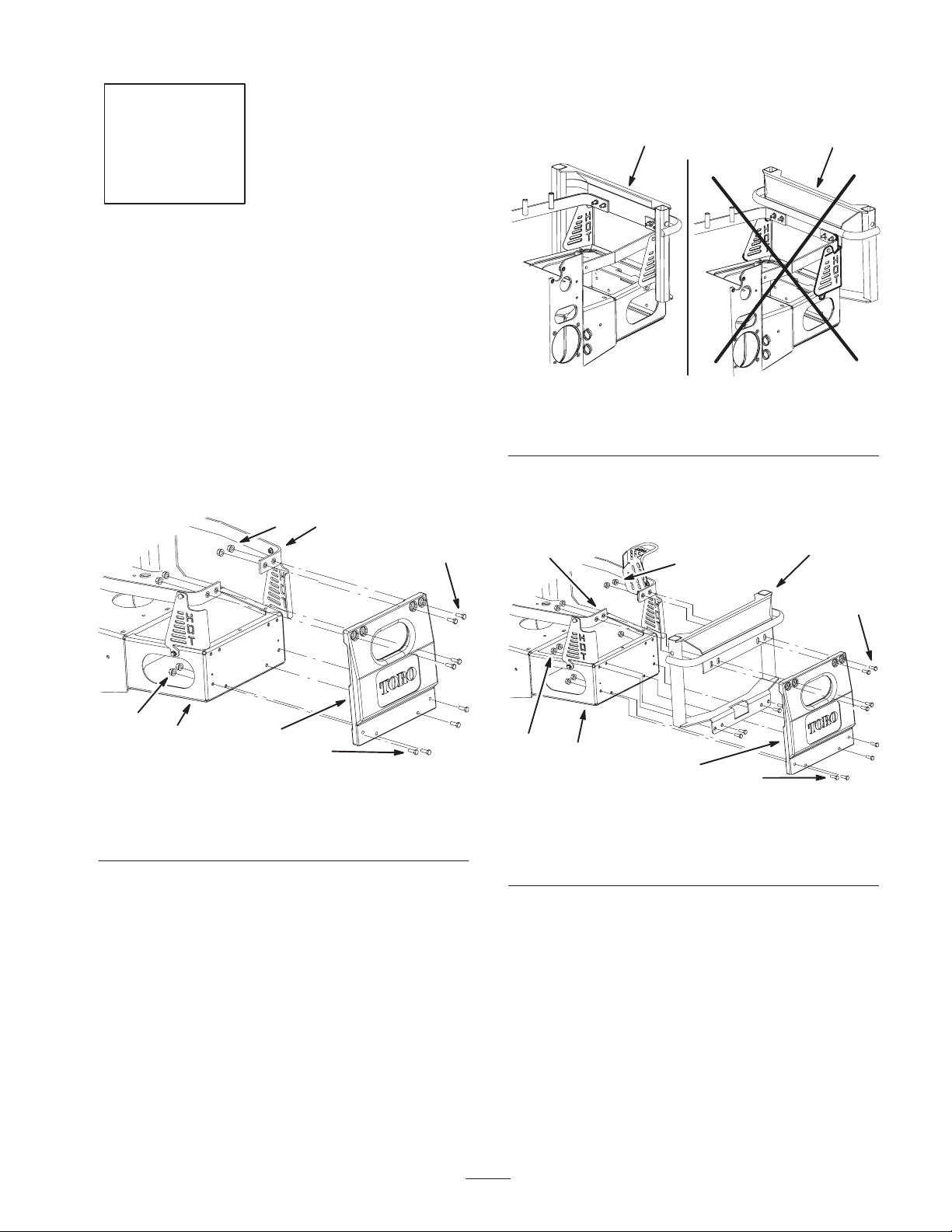
Note: Make sure to install the bagger bracket correctly, as
shown in Figure 12.
2
Parts needed for this step:
• 1 Bagger bracket
Installing the Bagger Bracket
(Z400 Mowers with 52in Mower
Decks)
Note: Use these instructions if machine is equipped with a
rear weight.
1. Remove the rear weight from the back of the machine
(Fig. 11). Save the bolts and flange nuts.
2
4
1
1
Figure 12
1. Correct position 2. Incorrect position
2. Install the bagger bracket and weight to the engine
straps, tailpipe guard, and rear bumper with the 8
existing bolts and nuts previously removed (Fig. 13).
5
3
2
1
m–7782
2
3
m–7783
1. Bolt
2. Flange nut
3. Rear bumper
5
Figure 11
4. Engine guard strap
5. Rear weight
2
1
3
m–7780
1. Bagger bracket
2. Bolt
3. Flange nut
4
6
Figure 13
4. Rear bumper
5. Engine guard strap
6. Rear weight
2
9
Page 10

Step
3
Parts needed for this step:
• 1 Blower assembly
Installing the Blower Assembly
Important Make sure the mounting plate is installed to
the mower. Refer to the Finishing Kit.
1. Disengage the PTO, set the parking brake, and chock or
block the drive wheels.
2. Turn off the engine, remove the key, and wait for all
moving parts to stop before leaving the operating
position.
3. Slide the blower assembly peg into the hole on the
mounting plate (Fig. 14).
2
3
1. Mower
2. Blower assembly
3. Blower assembly peg
5
1
4
m–8256
Figure 14
4. Mounting plate hole
5. Mounting plate
4. Close the blower assembly. (Fig. 18).
5. Check if the latch fully engages the front latch peg.
Refer to Checking and Adjusting the Blower Latch on
page 22.
Note: There must not be any gap between the blower
assembly and the mounting plate.
Step
4
Parts needed for this step:
• 1 Blower belt cover
• 1 Idler spring
• 1 Bagger belt
10
Page 11

Installing the Bagger Belt and
Idler Spring
2. Turn off the engine, remove the key, and wait for all
moving parts to stop before leaving the operating
position.
Important The idler spring and bagger belt need to be
installed together.
This will create slight tension on both the spring and belt
while installing them.
Installing the Idler Spring
1. Disengage the PTO, set the parking brake, and chock or
block the drive wheels.
2. Turn off the engine, remove the key, and wait for all
moving parts to stop before leaving the operating
position.
3. Open the blower assembly (Fig. 17).
4. Slide the spring into the blower eye bolt (Fig. 15).
5. Install the spring into the idler arm eye bolt (Fig. 15).
6. Close the blower assembly (Fig. 18).
5
4
3. Lower the deck to the 3 inch height–of–cut.
4. Push down on the front latch (colored red) and open the
blower assembly (Fig. 17).
5. For 52 inch mowers only, loosely install the belt cover,
insert the bagger belt under the belt cover and onto the
top mower pulley. Secure the belt cover latch (Fig. 16).
1
4
3
4
1
2
3
1
m–6276
Figure 15
1. Idler spring
2. Blower assembly
3. Idler arm eye bolt
4. Blower eye bolt
5. Idler arm
Installing the Bagger Belt
Note: For 44 inch (112 cm) mowers, make sure the right
rear corner of the cover side plate is modified. Refer to the
mower Finishing Kit.
1. Disengage the PTO, set the parking brake, and chock or
block the drive wheels.
3
m–6271
Figure 16
1. 52 inch mower belt cover
2. Blower assembly
3. Top mower pulley
4. Bagger belt
6. Route the bagger belt around the top pulley of the
mower pulley assembly (Fig. 17).
7. Feed the belt between the idler pulleys (Fig. 17).
8. Route the bagger belt around the spring–loaded idler
pulley (Fig. 17). The backside of belt will be touching
the pulley.
9. Route the bagger belt around the fixed idler pulley
(Fig. 17).
10. Route the bagger belt around the blower pulley
(Fig. 17).
2
11
Page 12

3
7
6
4
3 2
1
1
m–8257
5
2
Figure 17
1. Blower pulley
2. Mower
3. Blower assembly
4. Top pulley of mower
pulley assembly
5. Spring loaded idler pulley
(belt back side touching
pulley)
6. Fixed idler pulley
7. Front latch
11. Close the blower assembly and ensure the blower front
latch engages onto the front peg (Fig. 18).
1
m–8259
Figure 19
1. Blower assembly
2. Blower belt cover
3. Latch
14. For 44 inch (112 cm) mowers, install the new belt cover
over the pulley assembly and secure the latch (Fig. 20).
2
3
2
1
2
m–8258
Figure 18
1. Blower latch 2. Front peg
12. Adjust the bagger belt tension. Refer to Adjusting the
Bagger Belt Tension on page 22.
13. Install the belt cover over the pulley assembly and
secure the 3 cover latches into the blower (Fig. 20).
m–6255
1. Mower
2. 44 inch (112 cm) mower
belt cover
12
Figure 20
3. Latch
Page 13

Step
5
Parts needed for this step:
• 1 Hood assembly
• 2 Bags
• 2 Clevis pins
• 2 Hairpin cotter pins
Installing the Hood Assembly
and Bags
Warning
Components around engine will be hot if the
machine has been running. Touching hot
components can cause burns.
• Do not touch engine components when hot.
• Allow engine to cool before performing
maintenance.
1. Install the hood assembly into the bagger bracket
(Fig. 21).
2
1
m–6806
Figure 21
1. Bagger bracket 2. Hood assembly
2. Install clevis pins and hairpin cotters into the bagger
bracket and hood assembly (Fig. 22).
1
1. Hood assembly
2. Bagger bracket
13
3
4
2
Figure 22
3. Clevis pin
4. Hairpin cotter
m–6807
Page 14

3. Install the bag tab into the notch in the hood assembly
(Fig. 23). Do this for both bags.
Note: The bag will rest on the bagger frame (Fig. 23).
3
4. Lower the bagger hood over the bags.
1
3
4
1
1. Hood assembly
2. Bag
3. Bag tab
3
2
Figure 23
4. Notch
5. Bagger frame
4
5
2
m–6761
Figure 24
1. Hood
2. Bags
3. Bagger latch
4. Latch hook
5. Position the bagger latch under the latch hook
(Figures 24 and 25).
6. Push down on bagger latch until it locks into place
(Fig. 25).
m–6760
1
2
Figure 25
1. Bagger latch 2. Latch hook
m–6264
14
Page 15

Step
4
1
6
Parts needed for this step:
• 1 Bagger tube
• 1 Clamp
• 2 Knobs
• 1 Blower adapter
Installing the Bagger Tube
Note: To ease assembly of the bagger tube to the blower
adapter, apply soapy water to both the bagger tube and the
adapter.
1. Install one end of the tube, 4 to 4–1/2 inches (102 to
114 mm) onto the blower adapter and secure it with a
clamp (Fig. 26).
5
3
5
2
Figure 27
1. Tube
2. Blower assembly
3. Top blower stud
Note: There are nubs on the inside of the bagger hood that
hold the upper end of the bagger tube (Fig. 28).
4. Place the upper tube into the bagger hood (Fig. 28).
5. Move the upper tube back and forth, until at least two
ribs engage into the nubs inside the bagger hood
(Fig. 28).
4. Knob
5. Side blower stud
4
m–6252
4
3
2
Figure 26
1. Tube
2. Blower adapter
3. Clamp
4. 4 to 4–1/2 inches (102 to
114 mm)
2. Place the blower adapter over the top blower stud and
slide it into the side stud (Fig. 27).
3. Install the knobs onto the top and side stud (Fig. 27).
This will secure the lower tube end to the blower
assembly.
5. Tube installed onto the
adapter 4 to 4–1/2 inches
(102 to 114 mm)
m–6815
1
1
m–6263
1. Tube
2. Bagger hood
2
3
Figure 28
4
3. Nubs
4. Ribs
15
Page 16

Step
7
Parts needed for this step:
• No parts needed
Checking the Tire Pressure
Note: The tire pressure needs to increase due to the
additional weight.
Check and increase the air pressure in the front caster
wheels and rear tires (Fig. 29).
Pressure: Rear tires—20 psi (138 kPa)
Front caster wheels—25 psi (172 kPa)
1
Figure 29
1. Valve
stem
Check the Level of the Mower
Refer to the mower Operator’s Manual for the correct
procedure.
m–1872
16
Page 17

Operation
Caution
Note: Determine the left and right sides of the machine
from the normal operating position.
Important Set the parking brake when leaving the
machine unattended, even if just for a few minutes.
Warning
To avoid personal injury, follow these procedures:
• Become familiar with all operating and safety
instructions in the operator’s manual for your
mower before using this attachment.
• Never remove the bagger or bagger tubes while
the engine is running.
• Always shut the engine off and wait for all
moving parts to stop before clearing an
obstruction from the bagging system.
• Never do maintenance or repairs while the
engine is running.
• Set the parking brake.
Warning
Children or bystanders may be injured if they
move or attempt to operate the machine while it is
unattended.
Always remove the ignition key, set the parking
brake and chock or block tires when leaving the
machine unattended, even if just for a few minutes.
Positioning the Flow Baffle
(Z400 Mowers only)
The middle position or Position B is recommended for
bagging.
Move the adjustable flow baffle to the middle position. To
adjust the baffle refer to your mower Operator’s Manual.
Position B
Middle Position
Without the grass deflector, bagger tubes or
complete bagger assembly mounted in place, you
and others are exposed to blade contact and
thrown debris. Contact with the rotating mower
blade(s) and thrown debris will cause injury or
death.
• Always install the grass deflector when
removing the bagger and changing to side
discharge mode.
• If the grass deflector is ever damaged, replace it
immediately. The grass deflector routes material
down toward the turf.
• Never put your hands or feet under the mower.
• Never try to clear the discharge area or mower
blades unless you move the power take off
(PTO) to off and rotate the ignition key to off.
Also remove the key and pull the wire off of the
spark plug(s).
• Turn off the engine before unclogging the
discharge chute.
m–6880
Figure 30
Emptying the Grass Bags
Grass bags are heavy when full. Be careful when lifting or
handling a grass bag that is full.
1. Disengage the PTO, set the parking brake, and chock or
block the tires if on a slope.
2. Unlatch the bagger latch (Fig. 25).
3. Open the bagger hood.
4. Compress the debris into the bags. With both hands, lift
up on the bag and unhook it from the bagger bracket.
5. Grab the handle on the bottom of the bag and tip it over
to empty the bag (Fig. 31).
17
Page 18

4. Remove the knobs and then the tube from the blower
assembly (Fig. 27).
5. Remove the tube from the bagger hood (Fig. 28).
6. Using a stick or similar object, not your hands, to
remove and clear the obstruction from the tube
assembly.
1
m–6242
Figure 31
1. Bag 2. Bottom handle
6. Repeat for the other bag.
7. Install the bag tab into the notch in the bagger support
frame (Fig. 23). Do this for both bags.
8. Lower the bagger hood over the bags (Fig. 24).
9. Latch the bagger hood (Fig. 25).
Clearing Obstructions From
the Bagger System
2
Note: In most cases, the debris can be shaken out of the
tube.
7. If the blower assembly is plugged, unlatch the bagger
blower assembly and swing it open (Fig. 17).
8. Using a stick or similar object, not your hands, to
remove and clear the obstruction from the blower
assembly.
9. After you remove the obstruction, install the complete
bagger system and resume operation.
Removing the Bagger
Warning
Components around engine will be hot if the
machine has been running. Touching hot
components can cause burns.
• Do not touch engine components when hot.
• Allow engine to cool before removing the
bagger.
1. Disengage the PTO, set the parking brake, and chock or
block the drive wheels.
Danger
When the bagger is in operation, the blower can be
rotating and cut off or injure hands.
• Before adjusting, cleaning, repairing and
inspecting the blower, and before unclogging the
chute, turn off the engine and wait for all moving
parts to stop. Remove the key.
• Use a stick, not your hands, to remove an
obstruction from the blower and tube.
• Keep face, hands, feet, and any other part of
your body or clothing away from concealed,
moving, or rotating parts.
1. Disengage the PTO and set the parking brake.
2. Turn off the engine, remove the key, and wait for all
moving parts to stop before leaving the operating
position.
3. Empty the bags.
2. Turn off the engine, remove the key, and wait for all
moving parts to stop before leaving the operating
position.
3. Remove the knobs and then the tube from the blower
assembly (Fig. 27).
4. Remove the tube from the bagger hood (Fig. 28).
5. Unlatch the belt cover over the mower pulley assembly
(Fig. 20).
6. Open the blower assembly to release belt tension and
remove the bagger belt from the mower (Fig. 17).
7. Remove the blower assembly from the the mounting
plate (Fig. 14).
8. If you are changing to side discharge mode, ensure the
grass deflector is installed and can be lowered into
working position.
18
Page 19

Using the Grass Deflector
Transporting Machines
Note: Make sure the grass deflector is installed when the
bagger and tubes are removed.
Warning
Without the grass deflector, bagger tubes or
complete bagger assembly mounted in place, you
and others are exposed to blade contact and
thrown debris. Contact with the rotating mower
blade(s) and thrown debris will cause injury or
death.
• Always install the grass deflector when
removing the bagger and changing to side
discharge mode.
• If the grass deflector is ever damaged, replace it
immediately. The grass deflector routes material
down toward the turf.
• Never put your hands or feet under the mower.
• Never try to clear the discharge area or mower
blades unless you move the power take off
(PTO) to off and rotate the ignition key to off.
Also remove the key and pull the wire off of the
spark plug(s).
Do not leave grass or debris in the bagger while
transporting the machine.
Warning
Transporting the machine with grass or debris in
the bagger can damage the machine.
Do not leave grass or debris in the bagger while
transporting the machine.
Operating and Bagging Tips
Machine Size
Remember that the machine is longer and wider with this
attachment installed. By turning too sharply in confined
places you may damage the attachment or other property.
Trimming
Always trim with the left side of the mower. Do not trim
with the right side of the mower because you could damage
the blower assembly and bagging tube.
1. If the bagger is to be used for a long period of time,
leave the grass deflector off the machine. Install the
grass deflector when changing to side discharge mode.
2. If the bagger is to be used for a short period of time,
leave the grass deflector on the machine. The grass
deflector will rest against the belt cover.
Cutting Height
For optimum bagging performance, set the deck
height–of–cut to remove no more that 2 to 3 inches
(51 to 76 mm) or 1/3 of the grass height, which ever is less.
Cutting off more than this will reduce the capacity of the
vacuum system.
Cutting Frequency
Cut the grass often, especially when it grows rapidly. You
will have to cut your grass twice if it gets excessively long
Refer to Bagging Long Grass on page 20.
Cutting Technique
For best lawn appearance, be sure to slightly overlap the
mower into the previously cut area. This helps reduce the
load on the engine and reduces the chance of plugging the
blower assembly and tube.
Bagging Speed
The bagging system may plug if you drive too fast and the
engine speed gets too slow. On hills it may be necessary to
slow the machines ground speed. Mow down hill whenever
possible.
19
Page 20

Caution
As the bagger fills, extra weight is added to the
back of the machine. If you stop and start
suddenly on hills, you may lose steering control or
the machine may tip.
• Do not start or stop suddenly when going uphill
or downhill. Avoid uphill starts.
• If you do stop the machine when going uphill,
disengage the PTO. Then back down the hill
using a slow speed.
• Do not change speeds or stop on slopes.
Bagging Long Grass
If the grass is ever allowed to grow longer than normal, or
if it contains a high degree of moisture, raise the cutting
height higher than usual and cut and bag the grass at this
setting. Then cut and bag the grass again using the lower,
normal setting.
Excessively long grass is heavy and may not be propelled
completely into the bagger. If this happens, the tube and
blower assembly may plug.
Curb Climbing and Loading
Always lift the deck to the highest position when loading
the machine on trailers or ascending/descending a curb.
Leaving the mower in a lower position can cause damage to
mower baffles while loading and going over a curb. If a
curb is higher than 6 inches (152 mm), cross it at a sharp
angle with the deck fully raised. Use extreme caution
when loading onto a trailer.
Front Blowout
A bagging enhancement kit is available to reduce grass
blowout at the front of the mower deck. Excessive dust in
some dry conditions may also be reduced with this kit. This
kit is not available for 44 inch mower decks. Contact an
Authorized Service Dealer for the proper kit.
Bagging Wet Grass
If possible, always try to cut grass when it is dry. Wet grass
can cause plugging.
Reducing Plugging
To avoid plugging the bagging system, reduce ground
speed and mow the grass at a high height-of-cut, then lower
the mower to your normal cutting height and repeat the
bagging process.
Signs of Plugging
As you are bagging, a small amount of grass clippings
normally blow out the front of the mower. An excessive
amount of clipping blow-out indicates that the bagger is
full or the tube is plugged.
Bagging Blades
In most mowing conditions, the standard high lift blades
will provide the best bagging performance.
The Toro Atomic blade is recommended for bagging leaves
in dry conditions. In dry dusty conditions, the medium lift
or low lift blades with reduce dust and dirt blowout while
providing effective bagging air flow.
Contact an Authorized Service Dealer for the proper blades
for different mowing conditions.
20
Page 21

Maintenance
Important If the machine is on a slope, set the parking brake and chock or block the wheels to prevent the machine from
slowly rolling.
Recommended Maintenance Schedule
Maintenance Service
Interval
Each Use • Hood screen—clean
First 8 Hours
8 Hours • Bagger—clean
25 Hours
40 Hours • Blower liner—inspect
100 Hours • Bagger—inspect
Storage Service
Note: Determine the left and right side of the machine from the normal operating position.
Cleaning the Hood Screen
The screen needs to be cleaned before each use. In wet
grass it will need to be cleaned more often.
Maintenance Procedure
• Bagger—inspect
• Bagger belt—check and adjust
• Bagger belt—check and adjust
• Bagger idler arm—grease
• Belt—check for wear/cracks
• Bagger—inspect
• Bagger—clean
Cleaning the Bagger
The screen needs to be cleaned before each use. In wet
grass it will need to be cleaned more often.
1. Disengage the PTO, set the parking brake, and chock or
block the drive wheels.
2. Turn off the engine, remove the key, and wait for all
moving parts to stop before leaving the operating
position.
3. Open the bagger and hold the bagger hood open.
4. Clean the debris from the screen.
5. Close the bagger hood.
1. Wash the inside and outside of the bagger hood, tube,
and the underside of the mower. Use a mild automotive
detergent to remove dirt.
2. Make sure you remove matted grass from all parts.
3. After washing all parts, let them dry thoroughly.
Note: With all parts installed, start and run the machine for
a minute to assist in drying.
21
Page 22

Checking and Adjusting the
Bagger Belt Tension
Check the bagger belt tension every 25 hours.
6. Adjust the fixed idler towards the rear to lengthen the
spring and increase belt tension (Fig. 33).
7. Adjust the fixed idler towards the front to shorten the
spring and decrease belt tension (Fig. 33).
Note: When checking the belt tension, the spring length
needs to be between 4 inches and 4–3/4 inches (102 and
121 mm) (Fig. 32).
Important Adjust the bagger belt if the spring length is
4 inches (102 mm) or less or greater than 4–3/4 inches
(121 mm).
1. Disengage the PTO and set the parking brake.
2. Turn off the engine, remove the key, and wait for all
moving parts to stop before leaving the operating
position.
3. Close the blower assembly and measure between the
spring coil ends. See Figure 32 for measuring the spring
length and eye hook orientation.
5
2
2
8. Tighten the two bolts that hold the fixed idler to the
blower assembly (Fig. 33).
9. Close the blower assembly and measure the spring
length again. Adjust the fixed idler until the correct
spring length is achieved.
5
2
3
4
6
m–7781
Figure 33
1. Fixed idler
2. Blower assembly
3. Adjust idler to the front to
shorten the spring
4. Bolts
5. Adjust idler to the rear to
lengthen the spring
6. Extra holes for adjusting
belt tension
1
3
1
4
m–6275
Figure 32
1. Spring
2. End of spring coils
3. Blower assembly peg
4. Distance between spring
coil ends, 4 to
4–3/4 inches (102 mm to
121 mm)
5. Eye bolt
Note: When adjustment is needed, set the spring length
to 4–3/4 inches (121 mm) +/– 1/4 inch (6 mm) (Fig. 32).
4. If adjustment is needed, open the blower assembly to
remove tension from the bagger belt (Fig. 17).
5. Loosen the two bolts that hold the fixed idler to the
blower assembly (Fig. 33).
Important There are two extra holes in the blower
assembly that can be used to obtain the correct belt tension.
If needed, remove the fixed idler and install it in the extra
holes to get more belt tension adjustment (Fig. 33).
Checking and Adjusting the
Blower Latch
Note: Adjust the blower latch when it is does not engage
the front peg correctly and there is a visible gap between
the mounting plate and blower.
Note: A 9/16 inch thin wall deep socket is recommended
for this procedure.
1. Check that the bagger belt is properly installed and
routed correctly. Refer to the Belt Routing
2. Guide the rod hook onto the front peg and pull up on
the handle to lock the latch. Use the following
procedures to ensure the latch engages properly.
3. There must not be a gap between the mounting plate
and the blower assembly (Fig. 34). If there is a gap,
proceed to item 5 of this procedure and shorten the
latch.
22
Page 23

7. Tighten the lock nut at the end of the rod hook
(Fig. 35).
3
Top view
4
8. Check to make sure the latch locks and unlocks
properly. Repeatadjustments if needed.
Replacing the Blower Belt
Check the bagger belt for wear and cracks after the first
8 hours and then every 25 hours.
2
1
Figure 34
1. Blower assembly
2. Blower front latch (Red)
3. Gap shown
4. Front peg
4. The blower latch must engage the front peg properly. If
it does not, proceed to item 5 of this procedure and
lengthen the latch (Fig. 35).
3
4
m–8261
1. Disengage the PTO, set the parking brake, and chock or
block the drive wheels.
2. Turn off the engine, remove the key, and wait for all
moving parts to stop before leaving the operating
position.
3. Push down on the front latch and open the blower
assembly (Fig. 17). This will automatically remove the
tension from the blower belt.
4. For 52 inch mowers only, remove the bagger belt
between the top mower pulley and the mower belt cover
(Fig. 16).
5. For 44 inch mowers only, remove the mower belt
cover (Fig. 20).
6. Remove the blower belt cover (Fig. 36).
7. Remove the bagger belt from the top pulley of the
mower pulley assembly (Fig. 37).
3 2
1
G000928
2
Figure 35
1. Latch
2. Front peg
3. Locknut
4. Jam nut
5. Adjust the lock nut at the end of the rod hook so the
there is no gap between the blower and mower deck and
that it engages the front peg properly (Fig. 35).
6. Tighten the jam nut up against the block in the handle
(Fig. 35).
1
Figure 36
1. Blower assembly
2. Blower belt cover
3. Latch
8. Remove the bagger belt from the spring–loaded idler
pulley and the fixed idler pulley (Fig. 37).
23
m–8260
Page 24

9. Remove the bagger belt from the blower assembly
6
pulley (Fig. 37).
10. Install the new bagger belt. Refer to Installing the
Bagger Belt on page 11.
7
m–8257
3
1
5
2
4
Figure 37
1. Blower pulley
2. Mower
3. Blower assembly
4. Top pulley of mower
pulley assembly
5. Spring loaded idler pulley
6. Fixed idler pulley
7. Front latch
Greasing the Idler Arm
Grease the bagger belt idler arm every 25 hours (Fig. 38).
2
1
m–6251
Figure 38
1. Bagger idler arm 2. Grease zerk
Checking the Blower Liner
Check the blower liner inside the blower every 40 hours
and more often in extreme mowing and bagging conditions.
1. Remove the blower adapter and tube from the blower
(Fig. 27).
2. Check the liner for any excessive wear. Do not use your
hands to check the liner or remove debris.
3. Replace the liner if any excessive wear is noticed.
Replacing the Blower Liner
Contact an Authorized Service Dealer for replacing the
blower liner.
Inspecting the Bagger
Inspect the bagger attachment after the first 8 hours of
operation and 100 hours thereafter.
1. Disengage the PTO, set the parking brake, and chock or
block the drive wheels.
2. Turn off the engine, remove the key, and wait for all
moving parts to stop before leaving the operating
position.
24
Page 25

3. Check the tube, blower assembly, and the bagger hood.
Replace these parts if they are cracked or broken.
2. Install bolt and nut. Place J hook end of spring around
grass deflector (Fig. 39).
4. Check the bags, bagger frame, and screen. Replace any
parts that are cracked, worn or broken.
5. Tighten all nuts, bolts and screws.
Inspecting the Mower Blades
and Baffles
1. Inspect the mower blades and baffles regularly and
whenever a blade strikes a foreign object.
2. If blades or baffles are badly worn or damaged, install
new blades or baffles. Refer to your mower operator’s
manual for complete blade maintenance.
Installing Mower Blades
In most mowing conditions, the standard high lift blades
will provide the best bagging performance.
The Toro Atomic blade is recommended for bagging leaves
in dry conditions. In dry dusty conditions, the medium lift
or low lift blades with reduce dust and dirt blowout while
providing effective bagging air flow.
Contact an Authorized Service Dealer for the proper blades
for different mowing conditions.
Important The grass deflector must be lowered down
into position. Lift the deflector up to test that it lowers into
the full down position.
8
6
1
Figure 39
1. Bolt
2. Spacer
3. Locknut
4. Spring
5. Spring installed
6. Grass Deflector
4
2
3
5
10
m–6085
7. L end of spring, place
behind mounting bracket
before installing bolt
8. J hook end of spring
9. Mounting bracket
10. Straight end—possible
style of spring
7
Refer to the mower Operator’s Manual for more
information on installing blades.
Installing the Grass Deflector
The grass deflector spring will have either an L end or a
straight end (Fig. 39).
Note: Make sure the grass deflector is installed when the
bagger and tubes are removed.
Warning
An uncovered discharge opening could allow the
lawn mower to throw objects in the operator’s or
bystander’s direction and result in serious injury.
Also, contact with the blade could occur.
Never operate the lawn mower unless you install a
cover plate, a mulch plate, grass deflector or a
grass chute and catcher.
1. Place spacer and spring onto grass deflector. Place the L
or the straight end of spring behind deck edge.
Storage
1. Clean the bagger attachment. Refer to Cleaning the
Bagger on page 21.
2. Inspect the bagger attachment for damage. Refer to
Inspecting the Bagger on page 21.
3. Make sure the bags are empty and thoroughly dry.
4. Check the belt for wear or cracks.
5. Store the machine in a clean, dry place, out of direct
sunlight. If you must store the machine outside, cover it
with a weatherproof cover. This protects the plastic
parts and extends the life of the machine.
Note: Make sure the L or the straight end of spring is
installed behind deck edge before installing the bolt as
shown in figure 39.
25
Page 26

Troubleshooting
pg
Problem Possible Causes Corrective Action
Abnormal vibration.
Reduced bagging performance.
Blower and tube plug too
frequently.
1. Cutting blade(s) bent or
unbalanced.
2. Blade mounting bolt is loose. 2. Tighten blade mounting bolt.
3. Loose blower pulley or pulley
assembly.
4. Blower belt is worn or
damaged.
5. Blower impeller is out of
balance.
6. Blower impeller is bent. 6. Do not use machine. Replace
1. Low engine speed. 1. Always operate the bagger at
2. Plugged screen. 2. Remove debris, leaves or grass
3. Loose blower belt. 3. Adjust the blower belt tension.
4. A plugged tube. 4. Locate and remove plugged
5. Full bags. 5. Empty bags.
1. Bags are too full. 1. Dump more frequently.
2. Low engine speed. 2. Always operate the bagger at
1. Install new cutting blade(s).
3. Tighten the appropriate pulley.
4. Replace the blower belt.
5. Contact Authorized Service
Dealer.
bent impeller.
full throttle.
clippings from the screen.
debris.
full throttle.
Debris blowout.
Blower impeller does not spin
freely.
3. Grass is too wet. 3. Cut grass when dry.
4. Grass is too long. 4. Cut no more that 2 to 3 inches
(51 to 76 mm) or 1/3 of the
grass height, which ever is
less.
5. Plugged screen. 5. Remove debris, leaves or grass
clippings from the screen.
6. Ground speed is too fast. 6. Drive slower at full throttle.
7. Worn blower belt. 7. Replace belt.
1. Bags are too full. 1. Dump more frequently.
2. Ground speed is too fast. 2. Drive slower at full throttle.
3. Mower is not leveled. 3. See the mower operator’s
manual for leveling the mower.
1. Plugged blower. 1. Remove debris, leaves or grass
clippings from the blower
impeller.
2. Impeller not aligned. 2. Contact Authorized Service
Dealer.
26
Page 27

Page 28

Landscape Contractor
Equipment (LCE)
The Toro Total Coverage Guarantee
A Limited Warranty
Conditions and Products Covered
The Toro Company and its affiliate, Toro Warranty Company,
pursuant to an agreement between them, jointly promise to repair
the listed Toro product if defective in materials or workmanship.
This warranty applies to:
• ProLine Mid-Size Walk Power Mowers and Accessories
• Z Master Mid-Mount ZRTs and Accessories
The following time periods apply from the date of purchase:
Components
• Engines* 2 years
• Hydraulic Systems 2 years
• Traction Unit Frame 2 years
• Carrier Frame 2 years
• Deck Shells 2 years
• Deck Spindles 3 years Parts, 2 years Labor
• Z500 Series Clutches 2 years
• Remaining Components 1 year
This warranty includes the cost of parts and labor, but you must
pay transportation costs.
* Some engines used on Toro LCE products are warranted by the
engine manufacturer.
Warranty Period
Instructions for Obtaining Warranty Service
If you think that your Toro LCE product contains a defect in
materials or workmanship, follow this procedure:
1. Contact any Toro Authorized or Master Service Dealer to
arrange service at their dealership. To locate a dealer
convenient to you, access our website at www.Toro.com. You
may also call our Toro Customer Care Department toll free at
888-865–5676 (U.S. customers) or 888-865–5691 (Canada
customers).
2. Bring the product and your proof of purchase (sales receipt) to
the Service Dealer.
If for any reason you are dissatisfied with the Service Dealer’s
analysis or with the assistance provided, call us toll free at the
numbers above or write us at:
LCE Customer Care Department
8111 Lyndale Avenue South
Bloomington, MN 55420-1196
You must maintain your Toro product by following the maintenance
procedures described in the Operator’s Manual. Such routine
maintenance, whether performed by a dealer or by you, is at your
expense.
There is no other express warranty except for special emission
system coverage on some products. This express warranty does
not cover the following:
• Cost of regular maintenance service or parts, such as filters,
fuel, lubricants, tune-up parts, blade sharpening, brake and
clutch adjustments.
• Any product or part which has been altered or misused or
required replacement or repair due to normal wear, accidents,
or lack of proper maintenance.
• Repairs necessary due to improper fuel, contaminants in the
fuel system, or failure to properly prepare the fuel system prior
to any period of non-use over three months.
• Pickup and delivery charges.
• Operational misuse, neglect, or accidents.
• Repairs or attempted repairs by anyone other than an
Authorized Toro Service Dealer using Toro approved parts.
All repairs covered by this warranty must be performed by an
Authorized Toro Service Dealer using Toro approved replacement
parts.
Repair by an Authorized Toro Service Dealer is your sole
remedy under this warranty.
Neither The Toro Company nor Toro Warranty Company is
liable for indirect, incidental or consequential damages in
connection with the use of the Toro products covered by this
warranty, including any cost or expense of providing substitute equipment or service during reasonable periods of
malfunction or non-use pending completion of repairs under
this warranty.
Some states do not allow exclusions of incidental or
consequential damages, or limitations on how long an
implied warranty lasts, so the above exclusions and
limitations may not apply to you.
All implied warranties of merchantability (that the product is
fit for ordinary use) and fitness for use (that the product is fit
for a particular purpose) are limited to the duration of the
express warranty.
This warranty gives you specific legal rights, and you may
also have other rights which vary from state to state.
Owner Responsibilities
Items and Conditions Not Covered
General Conditions
Countries Other than the United States or Canada
Customers who have purchased Toro products exported from the United States or Canada should contact their Toro Distributor (Dealer)
to obtain guarantee policies for your country, province, or state. If for any reason you are dissatisfied with your Distributor’s service or
have difficulty obtaining guarantee information, contact the Toro importer. If all other remedies fail, you may contact us at Toro Warranty
Company.
Part No. 374-0037 Rev. E
 Loading...