

Page 1

DFS Vac Collection System
500 Series Z Master
Model No. 78506—Serial No. 230000001 and Up
Form No. 3350–769
Operator ’s Manual
Domestic English (EN)
Page 2
Contents
Introduction 2. . . . . . . . . . . . . . . . . . . . . . . . . . . . . . . .
Safety 3. . . . . . . . . . . . . . . . . . . . . . . . . . . . . . . . . . . . .
Safety and Instruction Decals 3. . . . . . . . . . . . . . . .
Setup 4. . . . . . . . . . . . . . . . . . . . . . . . . . . . . . . . . . . . .
Loose Parts 4. . . . . . . . . . . . . . . . . . . . . . . . . . . . . .
Removing the Drive Wheels 6. . . . . . . . . . . . . . . .
Removing the Roll Over Protection System
(ROPS) 7. . . . . . . . . . . . . . . . . . . . . . . . . . . . . . . . .
Installing the Bagger Mounting Bracket onto an
Air Cooled Machine 8. . . . . . . . . . . . . . . . . . . . . . .
Installing the Bagger Mounting Bracket onto a
Liquid Cooled Machine 9. . . . . . . . . . . . . . . . . . . .
Installing the Side Brackets to the Machine 10. . . . .
Tightening all Mounting Bolts 12. . . . . . . . . . . . . . .
Installing The Drive Wheels 13. . . . . . . . . . . . . . . . .
Removing the Mower Belt and the Right Rear Idler
Pulley 13. . . . . . . . . . . . . . . . . . . . . . . . . . . . . . . . .
Installing the Drive Pulley Assembly 14. . . . . . . . . .
Installing the Bagger 15. . . . . . . . . . . . . . . . . . . . . .
Installing the Bagger Tensioner Pulley and Belt 16.
Adjusting the Bagger Belt 18. . . . . . . . . . . . . . . . . .
Installing and Adjusting the Mower Belt 19. . . . . . .
Installing the Weights 20. . . . . . . . . . . . . . . . . . . . . .
Installing the Boot and Discharge Tubes 22. . . . . . .
Installing the Bagger Dump Handle 23. . . . . . . . . . .
Installing the Bagger Dump Lever Stop Bolt 23. . . .
Adjusting the Bagger Dump Lever 24. . . . . . . . . . . .
Checking the Tire Pressure 25. . . . . . . . . . . . . . . . . .
Operation 26. . . . . . . . . . . . . . . . . . . . . . . . . . . . . . . . . .
Positioning the Adjustable Baffle 26. . . . . . . . . . . . .
Opening the Bagger 26. . . . . . . . . . . . . . . . . . . . . . .
Holding the Bagger Door Open 27. . . . . . . . . . . . . .
Adjusting the Bagger Door Opening and Cable 27. .
Clearing Obstructions From the Bagger System 27.
Removing the Discharge Tubes 28. . . . . . . . . . . . . .
Removing the Bagger 28. . . . . . . . . . . . . . . . . . . . . .
Replacing the Grass Deflector 28. . . . . . . . . . . . . . .
Operating and Bagging Tips 29. . . . . . . . . . . . . . . . .
Maintenance 30. . . . . . . . . . . . . . . . . . . . . . . . . . . . . . . .
Recommended Maintenance Schedule 30. . . . . . . . .
Cleaning the Screens 30. . . . . . . . . . . . . . . . . . . . . .
Cleaning the Bagger 30. . . . . . . . . . . . . . . . . . . . . . .
Checking the Bagger Belt 30. . . . . . . . . . . . . . . . . . .
Greasing the Idler Arm 30. . . . . . . . . . . . . . . . . . . . .
Greasing the Fan Shaft Bearings 31. . . . . . . . . . . . .
Inspecting the Bagger 31. . . . . . . . . . . . . . . . . . . . . .
Page
Page
Inspecting the Mower Blades 31. . . . . . . . . . . . . . . .
Storage 31. . . . . . . . . . . . . . . . . . . . . . . . . . . . . . . . .
Troubleshooting 32. . . . . . . . . . . . . . . . . . . . . . . . . . . . .
Introduction
Read this manual carefully to learn how to operate and
maintain your product properly. The information in this
manual can help you and others avoid injury and product
damage. Although Toro designs and produces safe
products, you are responsible for operating the product
properly and safely.
Whenever you need service, genuine Toro parts, or
additional information, contact an Authorized Service
Dealer or Toro Customer Service and have the model and
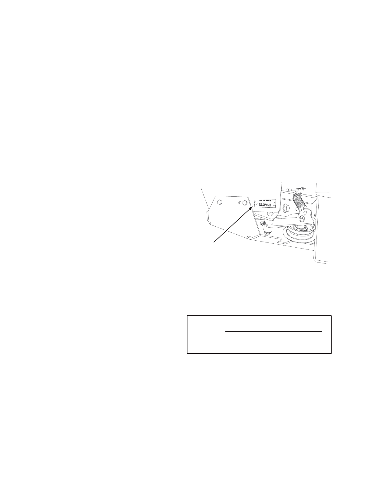
serial numbers of your product ready. Figure 1 illustrates
the location of the model and serial numbers on the
product.
1
m–6984
Figure 1
1. Location of the model and serial numbers
Write the product model and serial numbers in the space
below:
Model No.
Serial No.
This manual identifies potential hazards and has special
safety messages that help you and others avoid personal
injury and even death. Danger, Warning, and Caution are
signal words used to identify the level of hazard. However,
regardless of the hazard, be extremely careful.
Danger signals an extreme hazard that will cause serious
injury or death if you do not follow the recommended
precautions.
Warning signals a hazard that may cause serious injury or
death if you do not follow the recommended precautions.
2003 by The Toro Company
8111 Lyndale Avenue South
Bloomington, MN 55420-1196
All Rights Reserved
Printed in the USA
2
Page 3

Caution signals a hazard that may cause minor or moderate
injury if you do not follow the recommended precautions.
• The grass catcher can obstruct the view to the rear. Use
extra care when operating in reverse.
This manual uses two other words to highlight information.
Important calls attention to special mechanical
information and Note: emphasizes general information
worthy of special attention.
Safety
The following list contains safety information specific to
Toro products and other safety information you must know.
• Become familiar with the safe operation of the
equipment, with the operator controls, and safety signs.
• Use extra care with grass catchers or other attachments.
These can change the operating characteristics and the
stability of the machine.
• Follow the manufacturer’s recommendations for adding
or removing wheel weights or counterweights to
improve stability.
• Do not use a grass catcher on steep slopes. A heavy
grass catcher could cause loss of control or overturn the
machine.
• Slow down and use extra care on hillsides. Be sure to
travel in the recommended direction on hillsides. Turf
conditions can affect the machine’s stability. Use
extreme caution while operating near drop–offs.
• Keep all movement on slopes slow and gradual. Do not
make sudden changes in speed, directions or turning.
• Use care when loading or unloading the machine into a
trailer or truck
• Never operate with the discharge deflector raised,
removed or altered, unless using a grass catcher.
• Keep hands and feet away from moving parts. Do not
make adjustments with the engine running.
• Stop on level ground, disengage drives, chock or block
wheels, shut off engine before leaving the operator’s
position for any reason including emptying the grass
catcher or unclogging the chute.
• If you remove the grass catcher, be sure to install any
discharge deflector or guard that might have been
removed to install the grass catcher. Do not operate the
mower without either the entire grass catcher or the
grass deflector in place.
• Stop the engine before removing the grass catcher or
unclogging the chute.
• Do not leave grass in grass catcher for extended periods
of time.
• Grass catcher components are subject to wear, damage
and deterioration, which could expose moving parts or
allow objects to be thrown. Frequently check
components and replace with manufacturer’s
recommended parts, when necessary.
Safety and Instruction Decals
Safety decals and instructions are easily visible to the operator and are located near any area
of potential danger. Replace any decal that is damaged or lost.
104-8569
106-3339
3
Page 4

Setup
Note: Determine the left and right sides of the machine from the normal operating position.
Loose Parts
Note: Use the chart below to verify all parts have been shipped.
Step Description Qty. Use
1
2
3
4
No parts needed Removing the Drive Wheels
No parts needed
Bagger mounting bracket
Side bracket—right
Side bracket—left
Long frame spacer—only two are
needed for air cooled machines
Short frame spacer
Bolt, 3/8 x 1–1/2 inch
Bolt, 3/8 x 1–1/4 inch
Flange Nut, 3/8 inch
Stiffener bracket
Bolts, 3/8 x 3/4 inch
Bolt, 3/8 x 1 inch
Flange Nut, 3/8 inch
Curved washer
Spacer
1
1
1
4
2
12
4
26
2
8
6
6
6
4
Removing the Roll Over Protection
System (ROPS)
Installing bagger mounting brackets
onto the machine
Installing the side brackets to the
machine
5
6
7
8
No parts needed Installing the Drive Wheels
No parts needed Tightening all mounting bolts
No parts needed
Pulley assembly
Bolt, 1/2 x 1–1/4 inch
Lock nut,1/2 inch
Washer, 1/2 inch
1
4
4
4
4
Removing the mower belt and the right
rear idler pulley
Installing the drive pulley assembly
Page 5

Step UseQty.Description
9
10
11
12
13
Bagger
Clevis pin
Hairpin cotter
Bagger tensioner pulley
Bolt, 3/8 x 2 inch
Lock Nut, 3/8 inch
Washer, 3/8 inch
Bagger belt
No parts needed Adjusting the bagger belt
No parts needed Adjusting the mower belt tension
Caster weight
U–bolt
Nut, 1/2 inch
Lock washer, 1/2 inch
Plate
Top weight
Bolt, 1/2 x 3 inch
1
2
2
1
1
1
1
1
2
2
4
4
2
4
2
Installing the bagger
Installing the bagger tensioner pulley
and the bagger belt
Installing the weights
14
15
16
17
18
Boot
Middle Tube
Upper Tube
Clamp
Bagger dump lever
Washer, 13/16 inch
Cotter pin
Bolt, 1/2 x 1–3/4 inch
Jam nut, 1/2 inch
Long clevis (liquid cooled only)
No parts needed Adjusting the bagger dump lever
No parts needed Checking the tire pressure
1
1
1
1
1
2
1
1
2
1
Installing the boot and the discharge
tubes
Installing the bagger dump lever
Installing the bagger dump lever stop
bolt
5
Page 6
Step
1
No parts needed for this step.
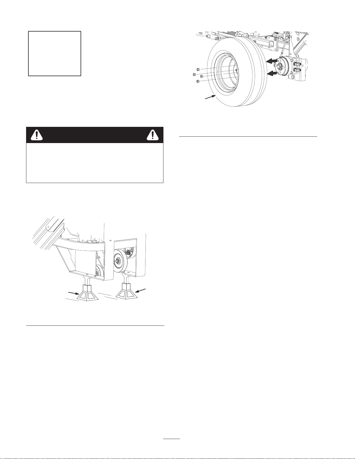
Removing the Drive Wheels
Danger
Mechanical or hydraulic jacks may fail to support
machine and cause a serious injury.
• Use jack stands when supporting machine.
• Do not use hydraulic jacks.
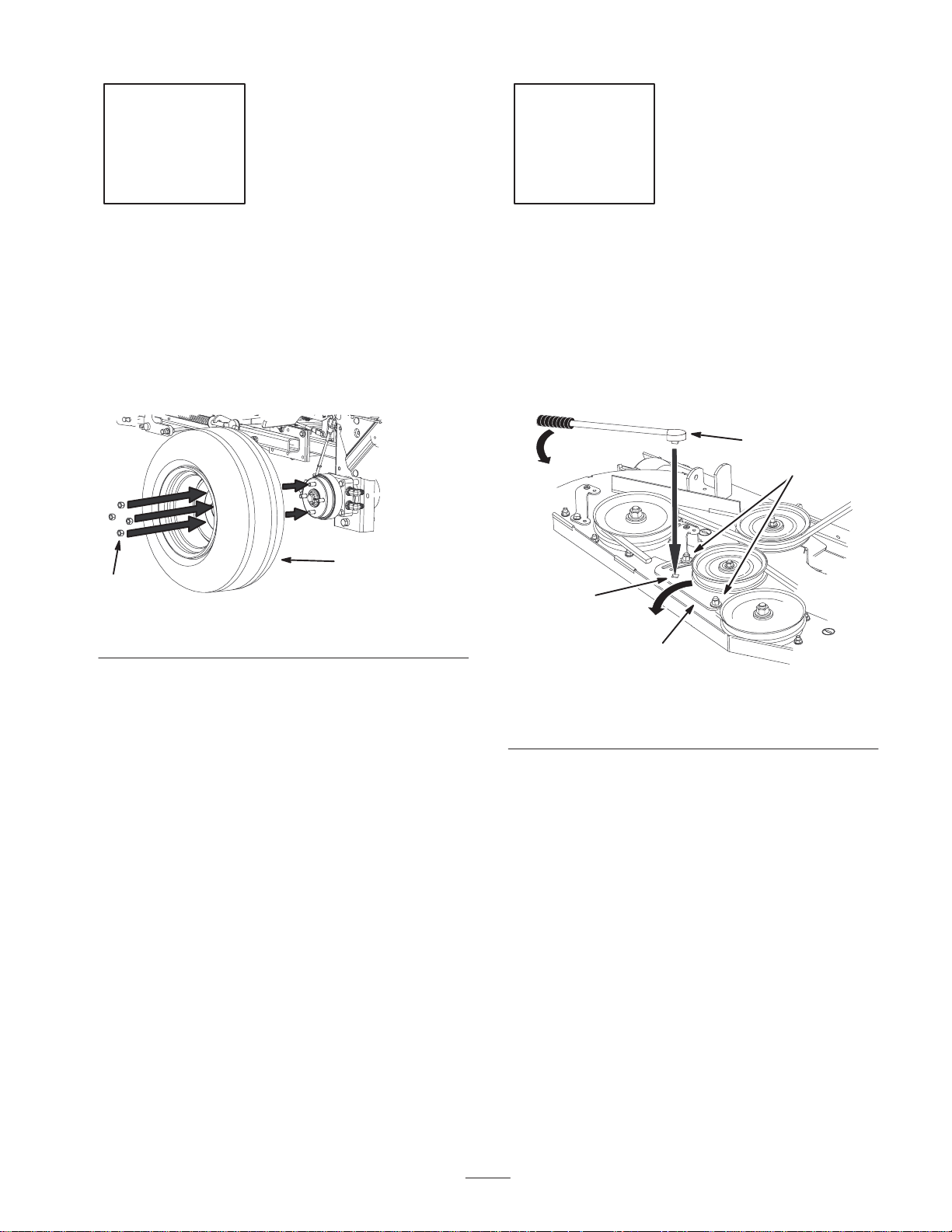
1. Loosen the drive wheel nuts.
2. Raise the rear of the machine and support with jack
stands (Fig. 2).
1
m–6859
Figure 3
1. Drive wheel
1
Figure 2
1. Jack stand
3. Remove the nuts and the drive wheels (Fig. 3).
1
6
Page 7
Step
2
No parts needed for this step.
1
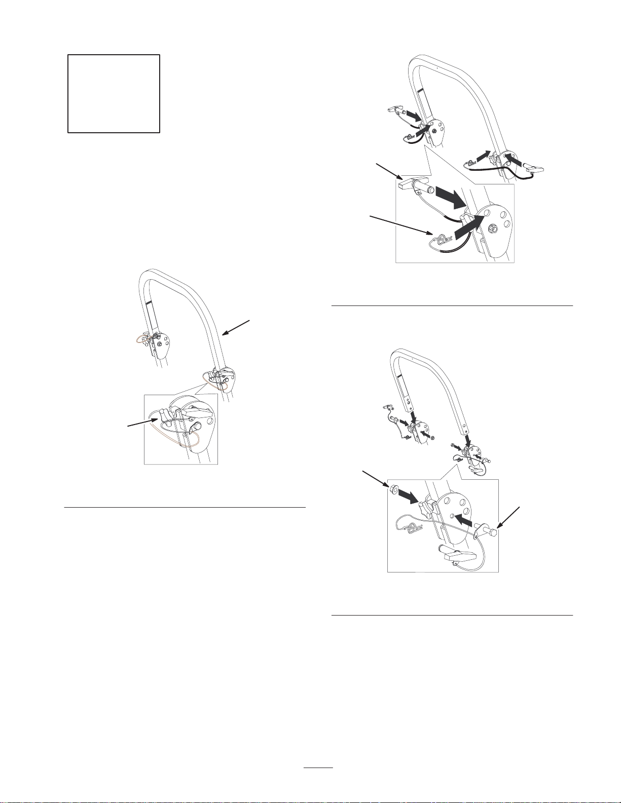
Removing the Roll Over
Protection System (ROPS)
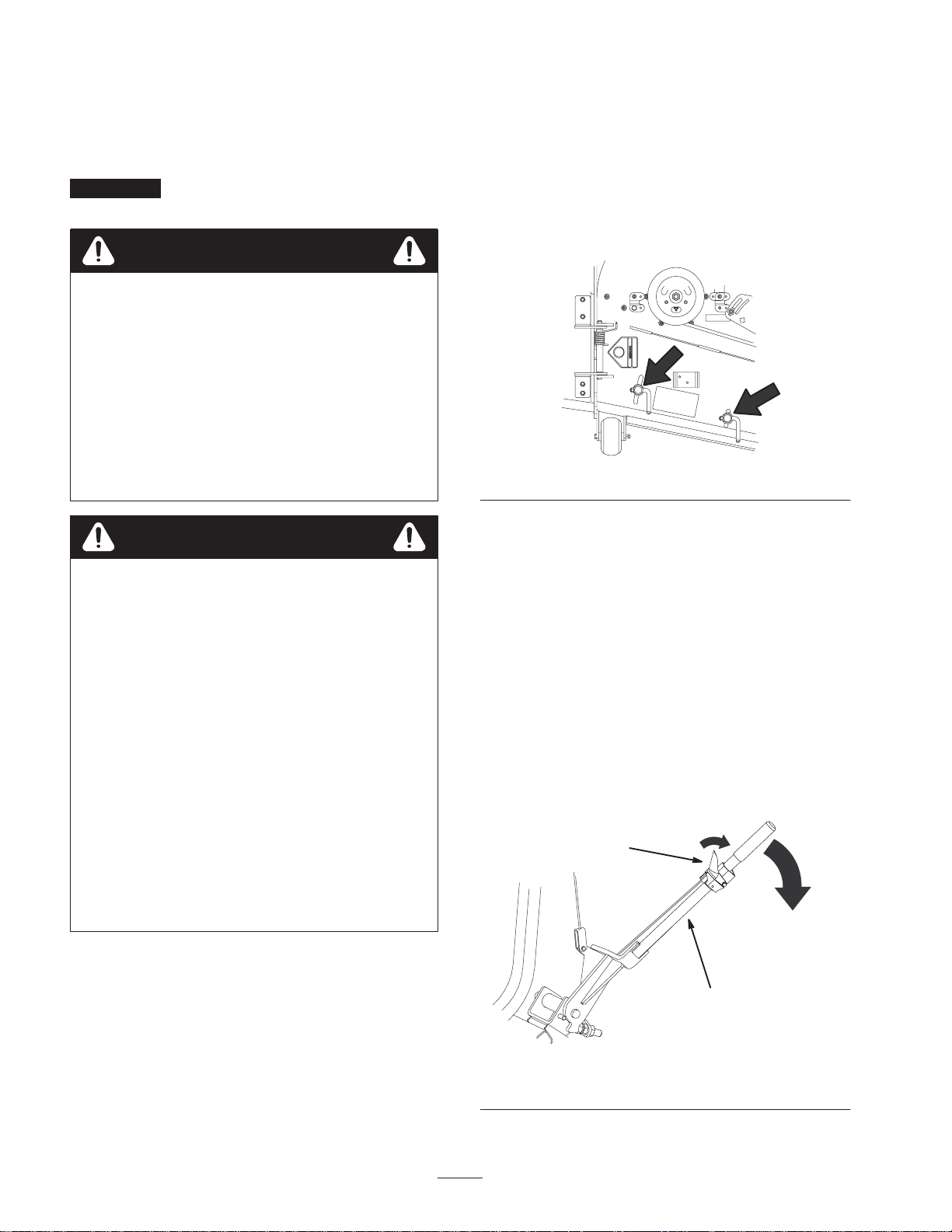
1. Loosen the front handles securing the center roll bar
section to the right and left sections (Fig. 4).
2
1
m–6835
Figure 4
1. Front handle 2. Center roll bar section
2
m–6893
Figure 5
1. Pin 2. Hair pin cotter
3. Loosen the center roll bar bolts allowing the roll bar to
be pivoted to the down position (Fig. 6).
2
1
2. Remove the hair pin cotters and pins securing the center
roll bar section to the right and left sections (Fig. 5).
Figure 6
1. Bolt 2. Flange nut
4. Remove the 2 bolts and 2 flange nuts securing the
center roll bar section to the right and left sections
(Fig. 6). Remove the center roll bar section.
7
Page 8
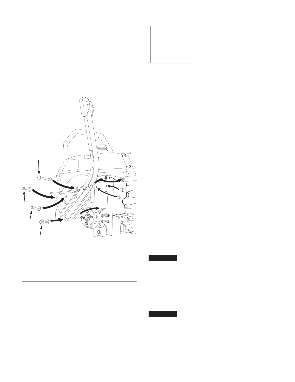
5. Remove the following fasteners (Fig. 7) securing each
(right and left) roll bar section to the frame:
• Lock nut (3/8 inch) and curved washer. Do not
remove bolt from frame.
Step
• Bolt (3/8 x 1 inch), curved washer and flange nut
(3/8 inch).
• Bolt (3/8 x 1 inch), curved washer and flange nut
(3/8 inch).
• Bolt (3/8 x 4-1/2 inches), curved washer and
flange nut (3/8 inch).
3
3
Parts needed for this step:
• 1 Bagger mounting bracket
• 1 Side bracket—right
• 1 Side bracket—left
• 4 Long frame spacer—only two are needed for air
cooled machines
• 2 Short frame spacer
• 12 Bolt, 3/8 x 1–1/2 inch
• 4 Bolt, 3/8 x 1–1/4 inch
• 26 Flange Nut, 3/8 inch
• 2 Stiffener bracket
• 8 Bolts, 3/8 x 3/4 inch
If you have a liquid cooled machine, go to page 9 for
Installing the Bagger Mounting Bracket onto a Liquid
Cooled Machine.
2
2
1
Figure 7
1. Lock nut, 3/8 inch &
curved washer
2. Bolt, 3/8 x 1 inch, curved
washer & flange nut,
3/8 inch (2)
6. Remove the roll bar section from frame (Fig. 7). Repeat
the procedure on the other roll bar section
3. Bolt, 3/8 x 4–1/2 inches,
curved washer & flange
nut, 3/8 inch
m–6854
If you have an air cooled machine, use the following
instructions for Installing the Bagger Mounting Bracket
onto a Air Cooled Machine.
Installing the Bagger Mounting
Bracket onto an Air Cooled
Machine
Important Do not tighten any bolts until both side
brackets and bagger mounting bracket are fit loose on the
machine.
Refer to Tightening the Mounting Bolts, on page 12, for the
correct procedure to tighten the bolts.
Installing the Bagger Mounting Bracket to
the Side Brackets (Air Cooled)
Important When installing the bagger bracket for an
air cooled machine, use only 2 long frame spacers; 1 per
each side (Fig. 8).
1. Install the side brackets to the bagger mounting bracket
(Fig. 8).
8
Page 9
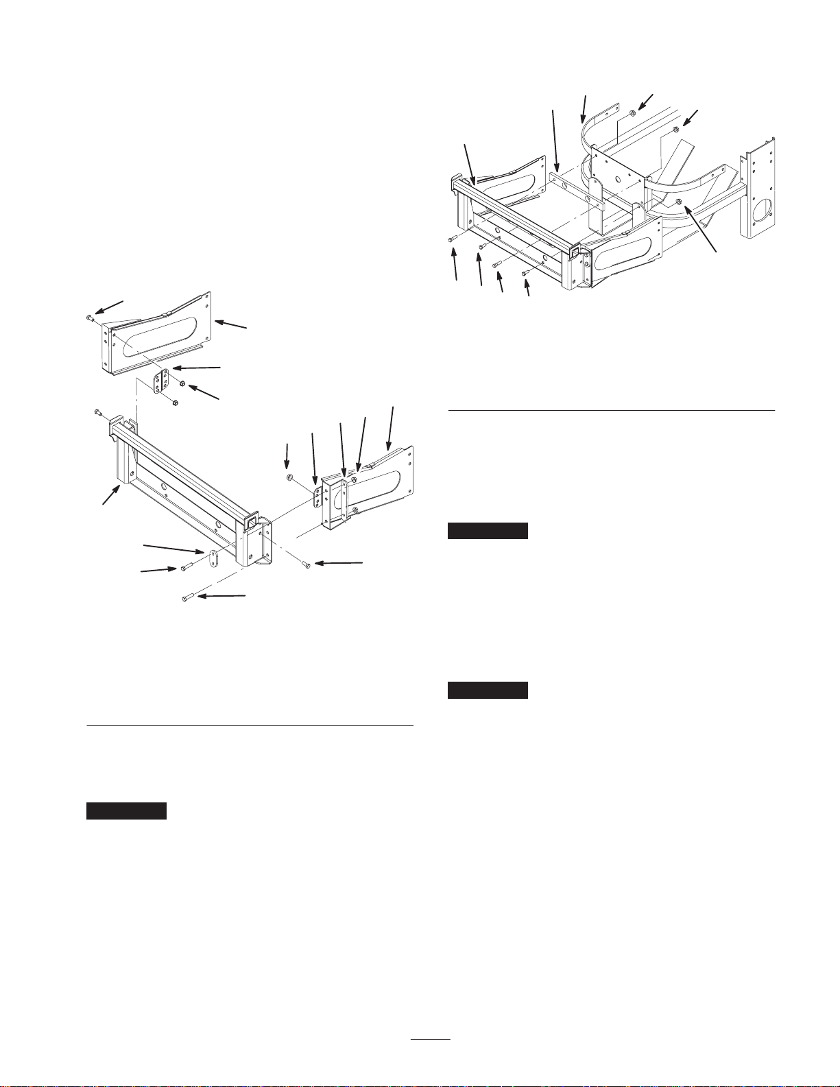
2. In the top two holes, install 2 bolts (3/8 x 1–1/2 inch),
2 flange nuts (3/8 in.) one long frame spacer, and one
short frame spacer (Fig. 8).
Note: Make sure the long frame spacers are installed as
shown in figure 8.
3. In the bottom hole, install a bolt (3/8 x 1–1/4 inch) and
a flange nut (3/8 in.) (Fig. 8).
4. Install a bracket stiffener to the side bracket and bagger
mounting bracket. Use 4 bolts (3/8 x 3/4 inch) and
4 flange nuts (3/8 in.) (Fig. 8).
5. Repeat the previous steps for the opposite side (Fig. 8).
6
5
4
3
7
4
3
10
3
4
5
3
3
1
3
6
2
6
2
m–5863
Figure 9
1. Bagger mounting bracket
2. Bolt, 3/8 x 1–1/4 inch
3. Flange nut, 3/8 inch
4. Bumper
5. Air cooled frame spacer
6. Bolt, 3/8 x 1–3/4 inch
Installing the Bagger Mounting
1
9
8
2
6
m–5978
Figure 8
1. Bagger mounting bracket
2. Bolt, 3/8 x 1–1/4 inch
3. Flange nut, 3/8 inch
4. Bracket stiffener
5. Left side bracket
6. Bolt, 3/8 x 3/4 inch
7. Long frame spacer
8. Bolt, 3/8 x 1–1/2 inch
9. Short frame spacer
10. Right side bracket
Installing the Bagger Mounting Bracket
onto an Air Cooled Machine
Important When installing the bagger onto an air
cooled machine, use the air cooled spacer (Fig. 9).
1. Install the bagger mounting bracket to the rear frame of
the machine (Fig. 9).
2. In the top two holes, install 2 bolts (3/8 x 1–3/4 inch),
2 flange nuts (3/8 in.) and the air cooled frame spacer
(Fig. 9).
3. In the bottom two holes, install 2 bolts (3/8 x
1–1/4 inch) and 2 flange nuts (3/8 in.) (Fig. 9).
Bracket onto a Liquid Cooled
Machine
Important Do not tighten any bolts until both side
brackets and bagger mounting bracket are fit loose on the
machine.
Refer to Tightening the Mounting Bolts, on page 12, for the
correct procedure to tighten the bolts.
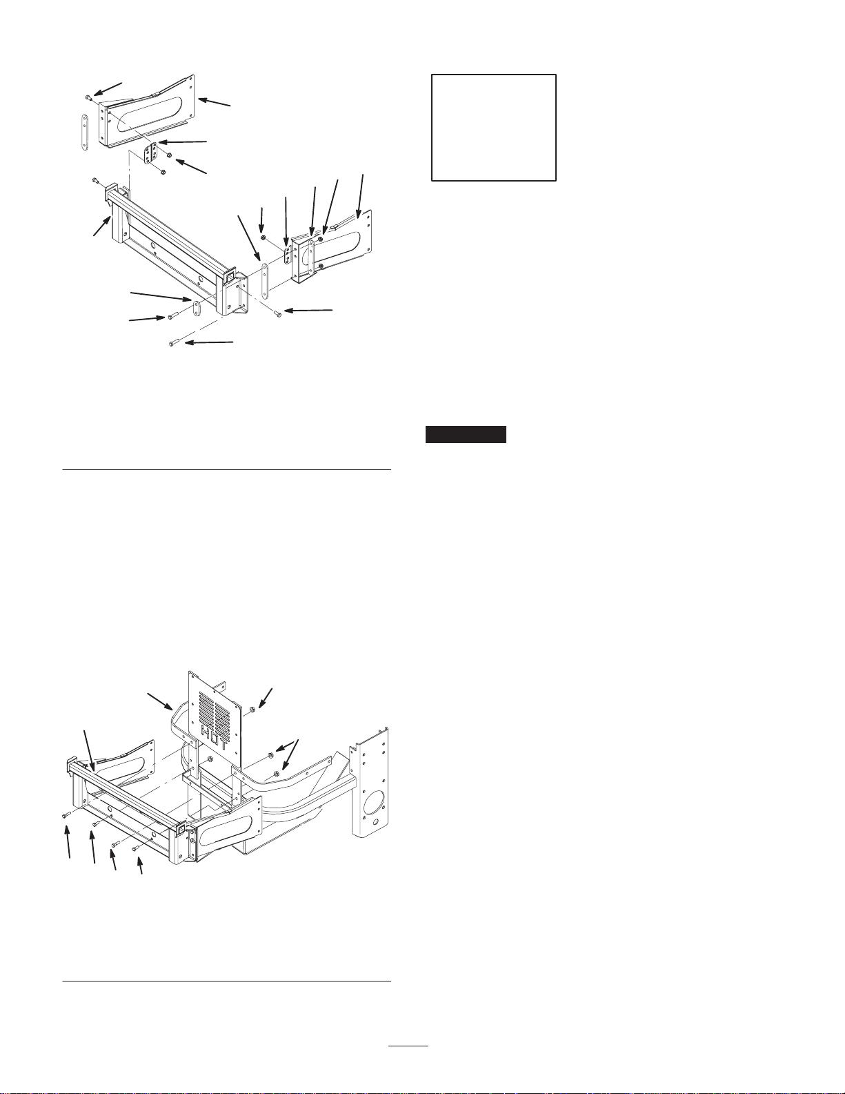
Installing the Bagger Mounting Bracket to
the Side Brackets (Liquid Cooled)
Important When installing the bagger onto a liquid
cooled machine, the rear bumper plate must be removed.
Use 4 long frame spacers for this installation, 2 per each
side (Fig. 10).
1. Install the side brackets to the bagger mounting bracket
(Fig. 10).
2. In the top two holes, install 2 bolts (3/8 x 1–1/2 inch),
2 flange nuts (3/8 in.), 2 long frame spacers, and one
short frame spacer (Fig. 10).
Note: Make sure the long frame spacers are installed as
shown in figure 10.
3. In the bottom hole, install a bolt (3/8 x 1–1/4 inch) and
a flange nut (3/8 in.) (Fig. 10).
4. Install a bracket stiffener to the side bracket and bagger
mounting bracket. Use 4 bolts (3/8 x 3/4 inch) and
4 flange nuts (3/8 in.) (Fig. 10).
5. Repeat the previous steps for the opposite side (Fig. 10).
9
Page 10
6
5
4
10
3
7
4
3
3
7
Step
4
1
9
8
1. Bagger mounting bracket
2. Bolt, 3/8 x 1–1/4 inch
3. Flange nut, 3/8 inch
4. Bracket stiffener
5. Left side bracket
2
Figure 10
6. Bolt, 3/8 x 3/4 inch
7. Long frame spacer
8. Bolt, 3/8 x 1–1/2 inch
9. Short frame spacer
10. Right side bracket
6
m–5979
Installing the Bagger Mounting Bracket
onto a Liquid Cooled Machine
1. Install the bagger mounting bracket to the rear frame of
the machine (Fig. 11).
2. In the top two holes, install 2 bolts (3/8 x 1–3/4 inch)
and 2 flange nuts (3/8 in.) (Fig. 11).
3. In the bottom two holes, install 2 bolts (3/8 x
1–1/4 inch) and 2 flange nuts (3/8 in.) (Fig. 11).
4
1
3
3
Parts needed for this step:
• 6 Bolt, 3/8 x 1–1/2 inch
• 6 Flange Nut, 3/8 inch
• 6 Curved washer
• 4 Spacer
Installing the Side Brackets to
the Machine
Important Do not tighten any bolts until both side
brackets and bagger mounting bracket are fit loose on the
machine.
Refer to Tightening the Mounting Bolts, on page 12, for the
correct procedure to tighten the bolts.
1. Install the bagger side plates and the roll bar sections
(Fig. 12) to each side of the mower using the following
fasteners:
• Lock nut (3/8 inch) and curved washer (Previously
removed).
• Bolt (3/8 x 4-1/2 inches), curved washer, spacer and
flange nut (3/8 inch) (Previously removed).
• Bolt (3/8 x 1–1/2 inch), curved washer, spacer and
flange nut (3/8 inch) (New).
• Bolt (3/8 x 1–1/2 inch), curved washer and
flange nut (3/8 inch) (New).
• Bolt (3/8 x 1–1/2 inch), curved washer and
flange nut (3/8 inch) (New).
5
2
5
2
1. Bagger mounting bracket
2. Bolt, 3/8 x 1–1/4 inch
3. Flange nut, 3/8 inch
Note: Make sure the curved washers and spacers are
installed as shown in figure 12.
Note: Hydraulic lines may need to be adjusted when
installing the side brackets onto the machine. This will
allow for fastener clearance.
m–5864
Figure 11
4. Bumper
5. Bolt, 3/8 x 1–3/4 inch
10
Page 11
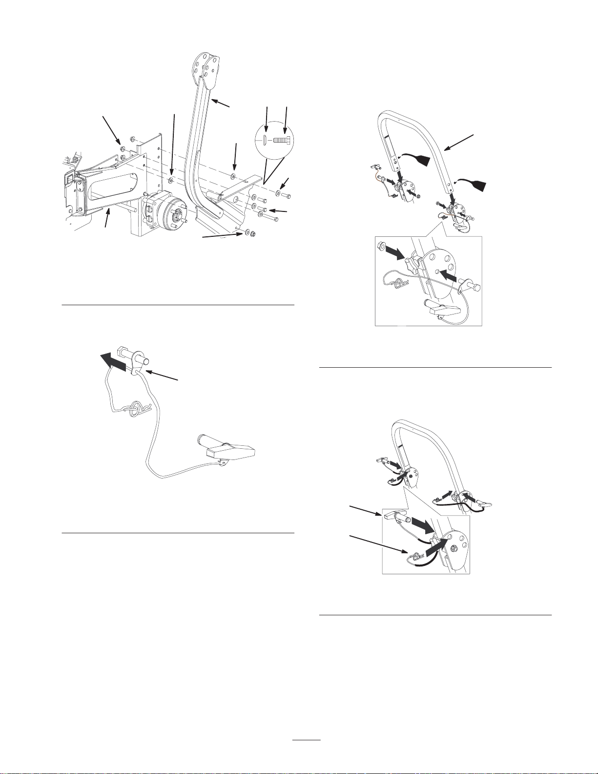
3
Note: Make sure the bolts are installed on the outside of the
roll bar.
Note: Make sure the lanyard tab is installed as shown and
4
6
5
32
points forward.
6
1
2
Figure 12
1. Side bracket
2. Curved washer, 3/8 inch
3. Bolt, 3/8 x 1–1/2 inch
4. Flange nut, 3/8 inch
5. ROPS
6. Spacer
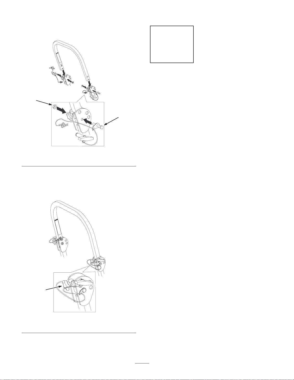
2. Make sure the lanyard clips are on the 2 bolts
(1/2 x 3-1/4 inches) (Fig. 13).
1
1
2
m–6891
Figure 14
1. Center roll bar section
5. Raise the roll bar into the upright position and secure it
with the pins and hairpin cotter pins fastened to the
lanyards (Fig. 15).
m–6892
Figure 13
1. Lanyard clip
Note: Make sure the bent tab points toward the head of the
bolt.
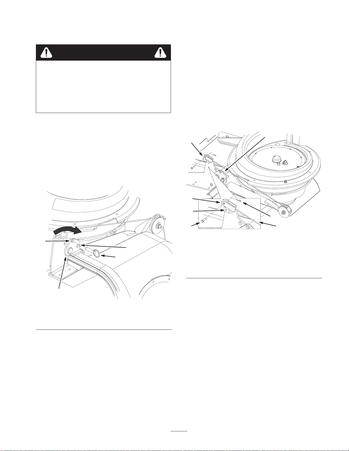
3. Lightly oil the ends of the center roll bar section
(Fig. 14).
4. Loosely install the center roll bar section, using 2 bolts
(1/2 x 3-1/4 inches) and 2 flange nuts (1/2 inch)
(Fig. 14).
1
2
m–6893
Figure 15
1. Pin 2. Hair pin cotter
6. Tighten the center roll bar bolts (1/2 x 3-1/4 inches) so
it rotates freely with some resistance (Fig. 16).
11
Page 12
Note: No more than one thread should be exposed outside
the nut.
Step
5
No parts needed for this step.
2
1
m–6891
Figure 16
1. Bolt 2. Flange nut
7. Torque all lower fasteners, attached to the machine
frame, to 30 ft–lb.
8. Tighten the front handles against the center roll bar
ends.
Tightening all Mounting Bolts
The following steps are the correct sequence to tighten the
side brackets and the bagger mounting bracket.
All 3/8 inch mounting bolts need to be torqued to 35 ft.–lb.
(48 Nm).
1. Tighten the bagger mounting bracket to the rear frame
first (Figures 9 or 11).
2. Tighten the bagger mounting bracket to the side
brackets (Figures 9 or 11).
3. Tighten the bracket stiffeners to both the side plates and
the bagger mounting bracket (Figures 8 or 10).
4. Tighten the side brackets to the side of the mower
(Fig. 12).
1
Figure 17
1. Front handle 2.
m–6835
12
Page 13
Step
Step
6
No parts needed for this step.
Installing The Drive Wheels
1. Mount the wheels with the valve stem to the outside and
secure them with the nuts previously removed (Fig. 18).
2. Torque the nuts to 95 ft-lb (128 Nm).
1
2
Figure 18
1. Drive wheel 2. Nuts
m–6859
7
No parts needed for this step.
Removing the Mower Belt and
the Right Rear Idler Pulley
1. Loosen the idler plate bolts and loosen the mower idler
plate (Fig. 19).
3
4
2
m–6826
1
3. Lower the machine onto the drive wheels.
1. Mower idler plate
2. Square hole
Figure 19
3. Ratchet or breaker bar
4. Idler plate bolt
13
Page 14
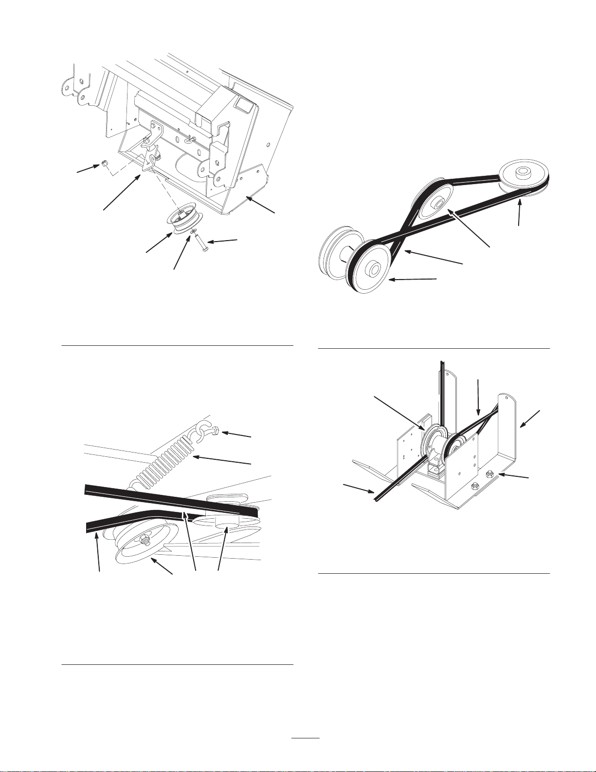
2. Remove the mower belt from the mower and the rear
fixed idler pulley (Fig. 20).
Step
1
3
5
4
2
6
Figure 20
1. Clutch
2. Mower belt
3. Right rear fixed idler
pulley
3. Remove the fixed idler pulley from the right rear frame
of the machine (Fig. 21).
4. Belt guide
5. Mower spindle pulley
6. Mower idler pulley
4
m–6825
8
Parts needed for this step:
• 1 Pulley assembly
• 4 Bolt, 1/2 x 1–1/4 inch
• 4 Lock nut, 1/2 inch
• 4 Washer, 1/2 inch
• 1 T emplate
Installing the Drive Pulley
Assembly
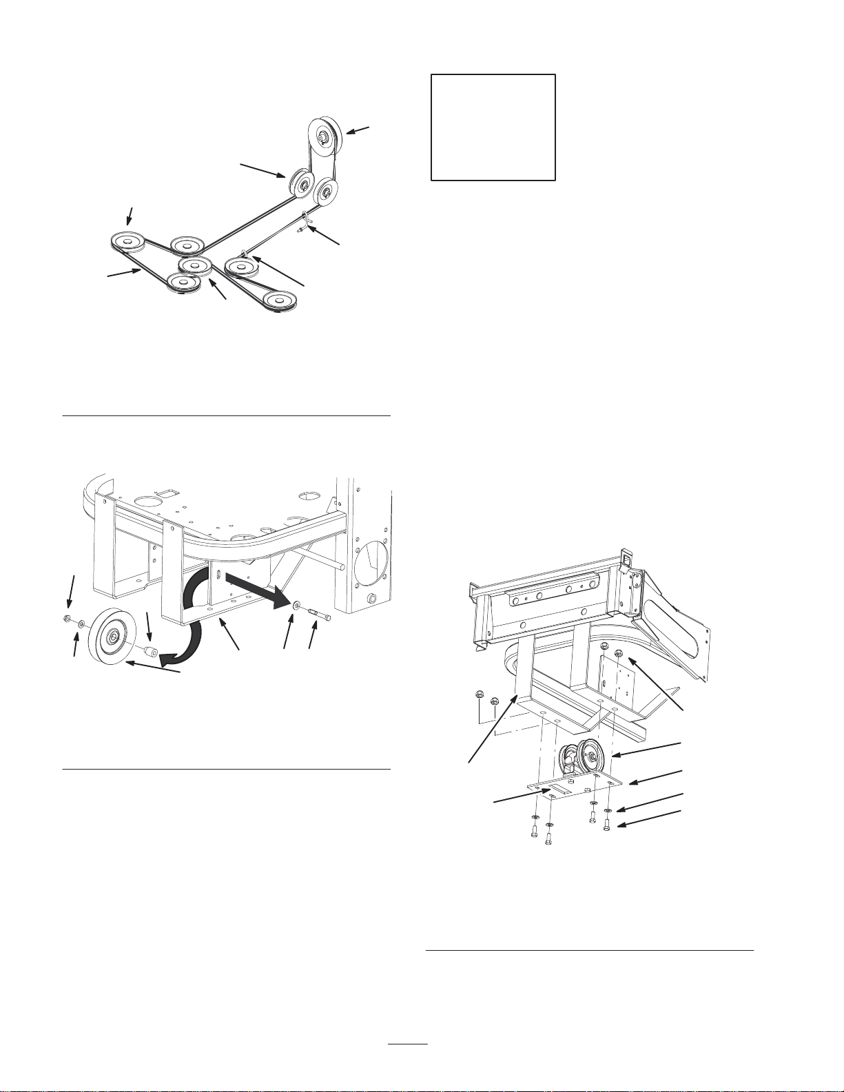
1. Install the mower belt onto the drive pulley assembly
(Figures 23 and 30).
Note: Make sure the cut–out in the pulley plate is on the
left–hand side of the machine (Fig. 22). This cut–out allows
room for the mower spring loaded idler pulley.
4
5
6
1. Fixed idler pulley
2. Right rear of the machine
3. Bolt
1
2
Figure 21
4. Nut
5. Spacer
6. Washer
3
6
m–7055
1
6
1. Rear frame
2. Drive pulley assembly
3. Bolt, 1/2 x 1–1/4 inch
4. Nut, 1/2 inch
4
2
7
5
3
m–6001
Figure 22
5. Washer, 1/2 inch
6. Cut–out
7. Pulley plate
14
Page 15
2. Install the pulley assembly under the rear frame, and
loosely install 4 bolts (1/2 x 1–1/4 inch), 4 washers
(1/2 in.) and 4 locknuts (1/2 inch) (Fig. 22). Do not
tighten bolts now.
Step
Positioning the Drive Pulley Assembly on
an Air Cooled Machine
1. Push the drive pulley assembly all the way forward and
then rearward a 1/4 inch (6 mm) (Fig. 22).
Note: The bolt head on the drive pulley assembly, should
be approximately centered horizontally, in the frame slot
(Fig. 23). View this from the right–hand side of the
machine.
2. Tighten the 4 bolts (1/2 x 1–1/4 inch), 4 washers
(1/2 in.) and 4 locknuts (1/2 inch) (Fig. 22).
Important A final adjustment may be needed when
installing the bagger belt.
Positioning the Drive Pulley Assembly on
a Liquid Cooled Machine
1. Push the drive pulley assembly all the way rearward and
then forward a 1/4 inch (6 mm) (Fig. 22).
Note: The bolt head on the drive pulley assembly, should
be approximately a 1/4 inch (6mm) rearward of the center
in the frame slot (Fig. 23). View this from the right–hand
side of the machine.
9
Parts needed for this step:
• 1 Bagger
• 2 Clevis pin
• 2 Hairpin cotter
Installing the Bagger
1. Install the bagger onto the bagger mounting bracket
(Fig. 24).
2. Install clevis pins into the bagger and bagger bracket.
Secure with hairpin cotters (Fig. 24).
3
2
3
1
4
6
Figure 23
1. Drive pulley assembly
2. Bolt head—air cooled
machine only
3. Mower drive belt
2. Tighten the 4 bolts (1/2 x 1–1/4 inch), 4 washers
(1/2 in.) and 4 locknuts (1/2 inch) (Fig. 22).
Important A final adjustment may be needed when
installing the bagger belt.
4. Bolt head—liquid cooled
machine only
5. Frame slot
6. 1/4 inch—liquid cooled
5
2
m–5861
4
1
Figure 24
1. Bagger
2. Bagger mounting bracket
3. Hairpin cotter
4. Clevis pin
Installing Bagger onto a Liquid Cooled
Machine
Note: The following instructions are for liquid cooled
machines only.
1. Loosen bolts that hold the engine shroud.
2. Move the engine shroud forward as far as possible.
M–6907
15
Page 16
3. Tighten bolts that hold the engine shroud.
4. Remove the cable guide and bolt from the frame of the
bagger (Fig. 25).
5. Install the cable guide, bolt, and nut with the cable
behind the cable guide (Fig. 25).
Note: Make sure the cable guide can rotate.
6. Locate template number 1 in the back of this manual.
Cut out template number 1 as indicated on the template
(Fig. 25).
7. Position the template on the right–hand side of the
engine shroud (Fig. 25).
Step
10
Parts needed for this step:
• 1 Bagger tensioner pulley
• 1 Bolt, 3/8 x 2 inch
8. Line up the mark on the template where the bagger
dump lever hits the engine shroud and the template
bottom is flush with the bottom of shroud (Fig. 25).
9. Tape the template to the engine shroud. Mark the outer
edge of the template. (Fig. 25).
10.Cut the engine shroud at the marked line. This will
prevent damage to the engine shroud while using the
bagger dump lever (Fig. 25).
Note: Make sure to follow the template outline. Do not
create any sharp corners.
2
4
1
5
m–6983
• 1 Lock Nut, 3/8 inch
• 1 Washer, 3/8 inch
• 1 Bagger belt
Installing the Bagger Tensioner
Pulley and Belt
1. Remove the four bolts in the skid plate (Fig. 26).
2. Remove the skid plate (Fig. 26). This will make it easier
to install the bagger belt.
1
2
m–6984
Figure 26
1. Bolts 2. Skid plate
7
1. Bagger dump lever
2. Engine shroud
3. Template
4. Cable guide
3
6
Figure 25
5. Mark on template
6. Template bottom
7. Shroud bottom
3. Install the bagger tensioner pulley onto the idler arm
with a bolt (3/8 x 2 inch), washer (3/8 inch), and lock
nut (3/8 inch) (Fig. 27).
16
Page 17
7. Install the tensioner spring onto the eyebolt attached to
the bagger (Fig. 28 and 31).
8. Adjust the bagger belt for proper tension. Refer to
Adjusting the Bagger Belt on page 18.
9. Adjust the Mower belt tension. Refer to Adjusting the
Mower Belt Tension on page 19.
10.Install the skid plate (Fig. 26).
3
2
1
5
4
Figure 27
1. Bolt, 3/8 x 2 inch
2. Idler arm
3. Lock nut, 3/8 inch
4. Washer, 3/8 inch
5. Bagger tensioner pulley
6. Bagger
4. Install the bagger belt onto the drive pulley
(Fig. 29 and 30).
5. Route the bagger belt onto the bagger pulley
(Figures 28 and 29).
6
3
2
M–6908
4
1
m–5773
Figure 29
1. Drive pulley
2. Bagger tensioner pulley
3. Bagger pulley
4. 1/4 twist
3
1
5
2
1
2
4
5
3
4
6
Figure 28
1. Tensioner spring
2. Eye bolt
3. Bagger tensioner pulley
4. Bagger pulley
5. Belt
6. Shortest space between
belt strands, 1 inch
±1/8 inch
Note: There should be a 1/4 twist in the belt when it is
installed onto the bagger tensioner pulley
6. Install the spring onto the idler arm (Fig. 28).
m–5887
1. Drive pulley assembly
2. Mower belt
3. Bagger belt
17
m–5892
Figure 30
4. Mounting bolts
5. Back of machine
Page 18
Step
11
No parts needed for this step
Adjusting the Bagger Belt
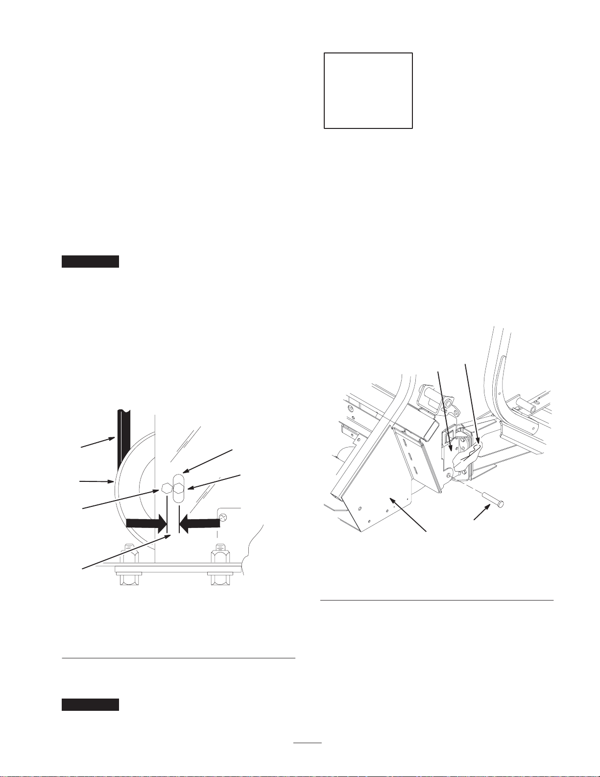
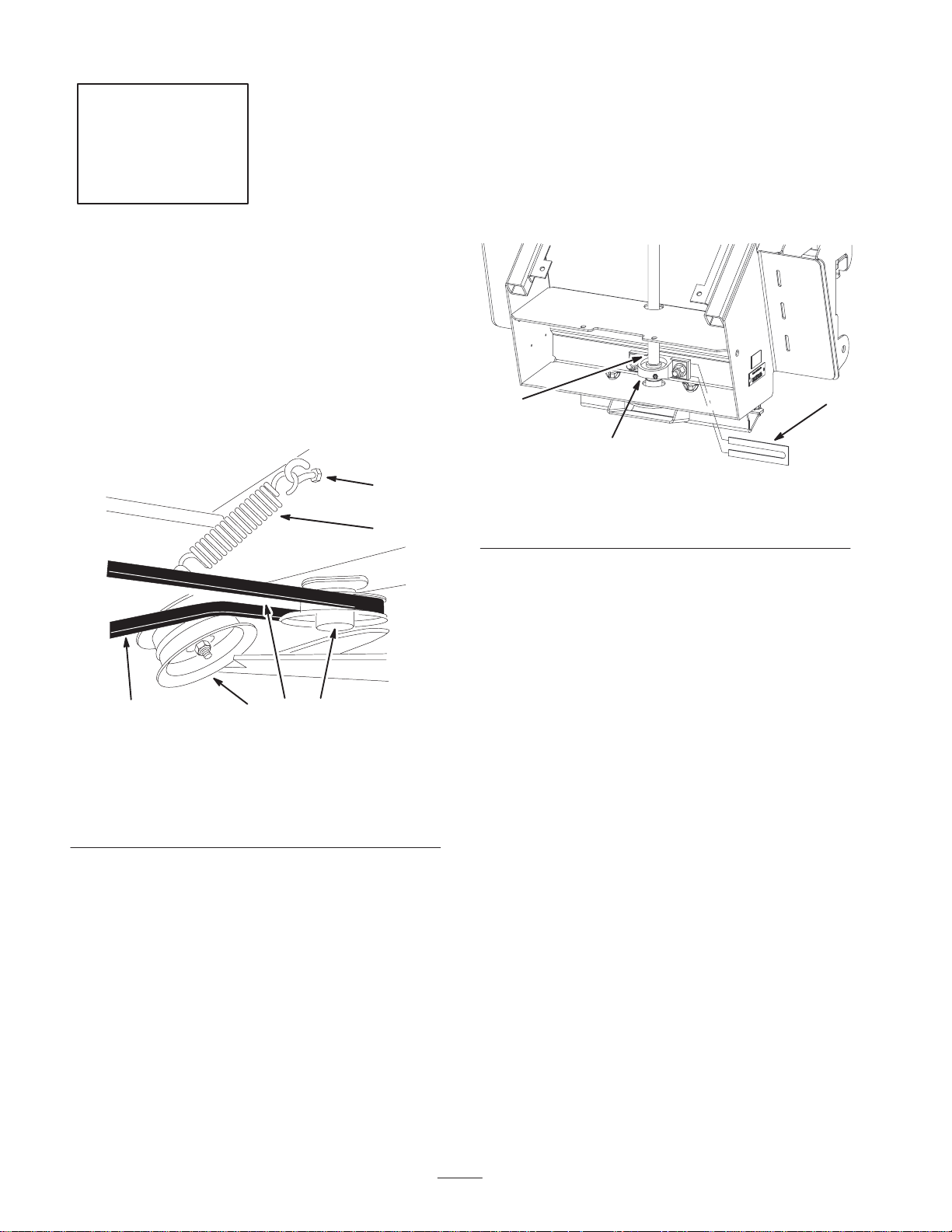
1. Check the belt tension (Fig 31).
2. Measure the gap, at the bagger tensioner pulley,
between the tight and slack side of the belt when the
bagger tensioner pulley and spring are installed
(Fig. 31).
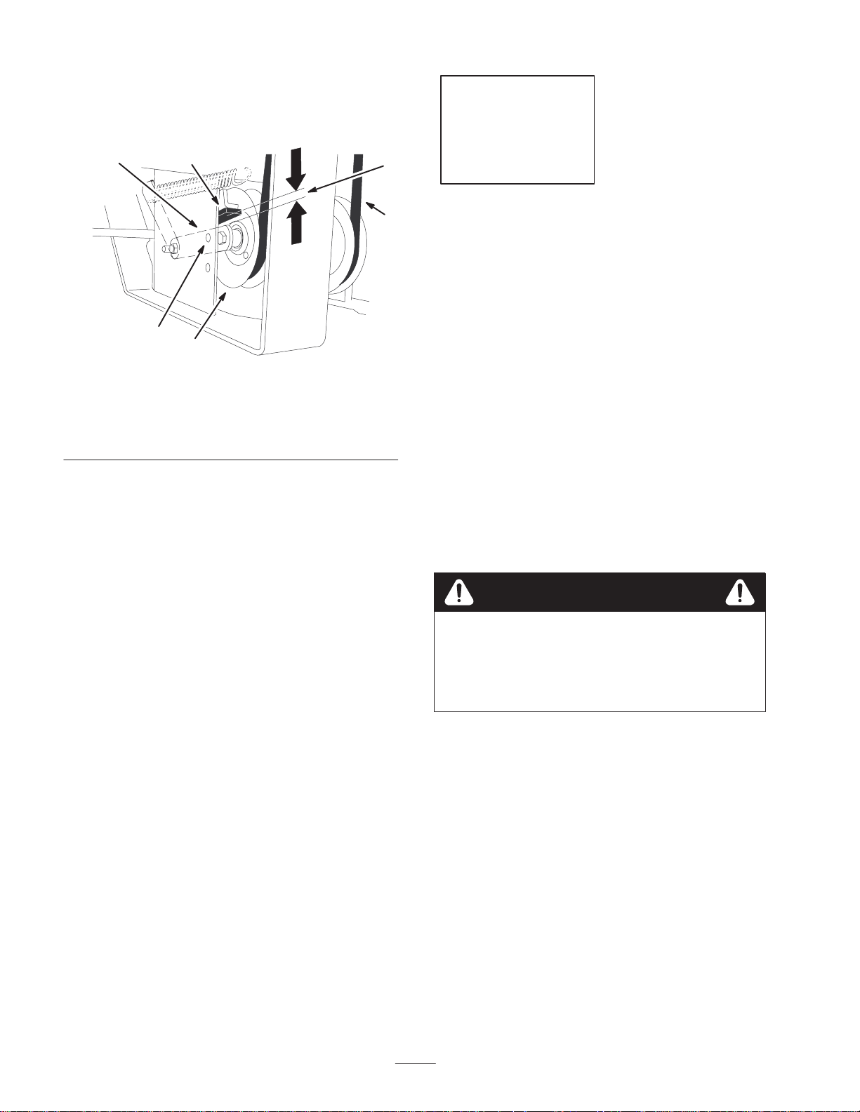
6. If the gap measurement is too small:
A. Loosen the 2 nuts on the lower fan shaft pillow
block (Fig. 32).
B. Insert a spacer behind the pillow block (Fig. 32).
C. Tighten the nuts.
D. Check the belt gap and repeat procedure as required.
2
1
3
2
1
4
6
5
1. Tensioner spring
2. Eye bolt
3. Bagger tensioner pulley
4. Bagger pulley
3. There must be a gap of 1 inch ± 1/8 inch (26mm ±
3 mm) between the belt strands (Fig 31).
4. If the gap is not correct, remove the tensioner spring
from the eyebolt and remove the tension on the mower
spring loaded idler (Fig 34).
3
Figure 31
5. Belt
6. Shortest space between
m–5887
belt strands, 1 inch
±1/8 inch
Figure 32
1. Pillow block
2. Fan shaft
7. Install the tensioner spring to the eyebolt and apply the
tension on the mower spring loaded idler.
8. Measure the bagger belt tension. There must be a gap of
1 inch ± 1/8 inch (26mm ± 3 mm) between the belt
strands (Fig 31).
9. Repeat this procedure if a gap of 1 inch ± 1/8 inch
(26mm ± 3 mm) was not achieved (Fig 31).
3. Spacer
5. If the gap measurement is too large:
A. Loosen the 4 mounting bolts holding the drive
pulley assembly (Fig 30).
B. Pull the pulley assembly rearward slightly
[1/8–3/16 inch (3–5 mm)] from the original set–up
position (Fig 30).
C. Tighten the 4 mounting bolts holding the drive
pulley assembly to the machine frame (Fig 30).
18
Page 19

Step
12
No parts needed for this step.
5. Check the belt tension. The spring loaded idler center
bolt needs to be near the top alignment hole in left
support plate (Fig 34).
1
2
Installing and Adjusting the
Mower Belt
1. Disengage the PTO, move the motion control levers to
the neutral locked position and set the parking brake.
2. Stop the engine, remove the key, and wait for all
moving parts to stop before leaving the operating
position.
3. Raise the mower to the transport position.
4. Ensure the mower belt is installed on all mower pulleys
(Fig 33).
Important Check the amount of twist in the belt
between the pulleys. Make sure it is only what is specified
in Figure 33.
3
5
3
1
3
3
1
Figure 34
1. Center bolt
2. Alignment hole
6. If adjustment is required, loosen the mower idler plate
and adjust it (Fig. 35).
7. Insert a ratchet or breaker bar into the square hole in the
mower idler plate to adjust the tension (Fig. 35).
8. To increase belt tension, rotate the mower idler plate
until resistance is felt and rotation stops. Do not go past
when it stops (Fig. 35).
9. Tighten the idler plate bolts (Fig. 35).
3. Left support plate
4. Spring loaded idler
3
4
M–4417
4
2
6
Figure 33
1. Clutch
2. Mower belt
3. 1/4 turn belt twist
Important Check and make sure the belt is installed
into both the front and rear belt guides (Fig 34).
4. Belt guide
5. Mower spindle pulley
6. Mower idler pulley
3
4
m–6825
m–6826
1. Mower idler plate
2. Square hole
19
2
1
Figure 35
3. Ratchet or breaker bar
4. Idler plate bolt
Page 20
10.Check the distance from the rubber stop and the arm of
the spring loaded idler pulley when the idler plate is
tightened. It needs to be 0 to 1/4 inch (0 to 6 mm) from
the rubber stop (Fig. 36).
Step
4
m–6825
1. Spring loaded idler pulley
2. Top alignment hole
3. 0 to 1/4 inch gap
(0 to 6 mm)
11. Adjust the belt tension and the idler plate, if necessary,
and tighten all hardware securely (Fig. 35).
6
2
1
Figure 36
4. Idler pulley arm
5. Belt
6. Rubber bumper
3
5
13
Parts needed for this step:
• 2 Caster weight
• 2 U–bolt
• 4 Nut, 1/2 inch
• 4 Lock washer, 1/2 inch
• 2 Plate
• Top weight
• 2 Bolt, 1/2 x 3 inch— for two top weights
Installing the Weights
To comply with ANSI/OPEI B71.4–1999 Standard, top
weights must be added to the machine.
Installing the Caster Weights
Caution
The bagger adds a lot of weight to the rear of the
machine and may cause an unstable condition
which could result in a loss of control.
• Install the front caster weights and top weights.
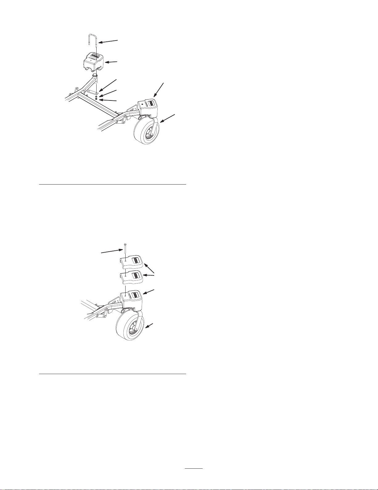
1. Place caster weights on the front casters.
2. Install plate, nuts (1/2 inch) and lock washer (1/2 inch)
under the frame and weight (Fig. 37).
3. Repeat for opposite side.
Note: On Z–Master mowers with 52 inch mower decks and
liquid cooled Z–Master mowers with 60 inch mowers
additional weights are required.
20
Page 21
2
1
3
1
6
4
m–5882
Figure 37
1. Front caster weight
2. U–bolt
3. Plate
4. Nut
5. Front caster
6. Lock washer
Installing the Extra Top Weights
1. Install 2 top weights on top of each caster weight and
secure them with a bolt (1/2 x 3 inch) (Fig. 38).
2
5
1. Top weight
2. Bolt, 1/2 x 3 inches
1
3
4
m–5882
Figure 38
3. Front caster weight
4. Front caster wheel
21
Page 22

Step
14
6. Place the rear hook over the rear of the mounting
bracket (Fig. 40).
7. Install the upper tube into the bagger (Fig. 40).
8. Slide the clamp onto the middle tube (Fig. 40).
9. Align the knob on the middle tube with the notch in the
upper tube. Slide the middle tube into the upper tube
and twist the middle tube 60 degrees (Fig. 40).
Parts needed for this step:
• 1 Boot
• 1 Middle tube
• 1 Upper tube
• 1 Clamp
Installing the Boot and
Discharge Tubes
Note: Remember to replace the L or the straight end of the
spring when in side discharge mode. Refer to Replacing the
Grass Deflector on page 28.
1. Disengage the PTO and set the parking brake.
2. Stop the engine, remove the key, and wait for all
moving parts to stop before leaving the operating
position.
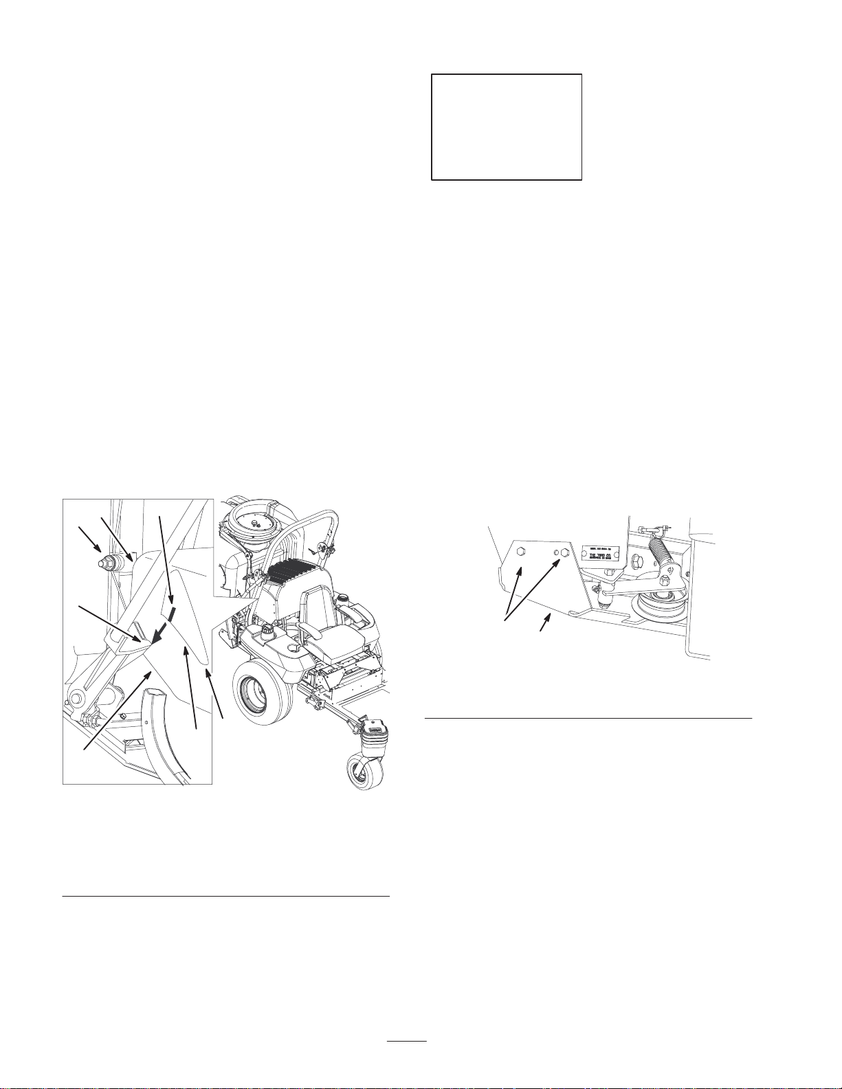
3. To relieve the spring tension on the grass deflector,
place the L or the straight end of the spring in front of
the mounting bracket (Fig. 50).
4. Lift the grass deflector all the way back.
5. Position the boot’s front hook into the front slot on the
mounting bracket (Fig. 40).
Note: If the grass deflector interferes with the boot, grind
off part of the grass deflector frame. See Figure 39 for the
correct part to grind off.
1
2
10.Tighten the clamp around the upper and middle tube
connection (Fig. 40).
11. Slide the middle tube onto the boot and latch them
together (Fig. 40).
11
3
6
2
5
1
10
8
7
Figure 40
1. Boot
2. Middle tube
3. Knob
4. Upper tube
5. Latch
6. Notch in upper tube
9
M–6910
7. Mounting bracket
8. Front slot
9. Rear hook
10. Front hook
11. Clamp
4
Figure 39
1. Grass deflector frame 2. Grind this part off
m–7056
22
Page 23

Step
Step
15
Parts needed for this step:
• 1 Dump handle
• 2 Washers, 13/16 inch
• 1 Cotter pin
Installing the Bagger Dump
Handle
1. Unfasten the dump handle from the crate.
2. Install a washer onto the bagger dump handle and install
the bagger dump handle into the bagger frame (Fig. 42).
3. Fasten the bagger with a washer ( inch) and a cotter
pin (Fig. 42).
3
16
Parts needed for this step:
• 1 Bolt, 1/2 x 1–3/4 inch
• 2 Jam nuts, 1/2 inch
• 1 Long clevis, liquid cooled machines only
Installing the Bagger Dump
Lever Stop Bolt
1. Move the bagger dump lever rearward to increase the
slack in the bagger cable (Fig. 42).
2. Remove the cotter pin and clevis pin securing the
bagger cable clevis to the bagger dump handle
(Fig. 42).
2
3
1. Dump handle
2. Washer
214
Figure 41
3. Cotter pin
4. Bagger frame
m–7054
1
6
2
4
Figure 42
1. Bagger dump lever
2. Bagger cable
3. Bagger cable clevis
3. Thread a jam nut (1/2 inch) all the way onto the bolt
(1/2 x 1–3/4 inch) (Fig. 42).
4. Move the bagger dump lever forward to move the
bottom of the lever away from the stop bracket
(Fig. 42).
5. Insert the bolt into the stop bracket hole and thread
another jam nut (1/2 inch) onto the bolt. Do not tighten.
4. Bolt, 1/2 x 1–3/4 inch
5. Jam nut, 1/2 inch
6. Stop bracket
5
m–6985
23
Page 24

Note: Install the long cable clevis onto the bagger dump
handle if it is for a liquid cooled machine (Fig. 43).
6. Secure the bagger cable clevis to the bagger dump
handle with the clevis pin and cotter pin previously
removed (Fig. 42 or Fig. 43).
Step
17
2
8
4
1. Bagger dump lever
2. Bagger cable
3. Long cable clevis—liquid
cooled machines only
4. Bolt, 1/2 x 1–3/4 inch
7. Adjust the handle stop, refer to Adjusting the Bagger
Dump Lever, page 24.
4
Figure 43
3
5. Jam nut, 1/2 inch
6. Stop bracket
7. Clevis pin
8. Cotter pin
1
7
6
5
m–6986
No parts needed for this step.
Adjusting the Bagger Dump
Lever
The bagger lever needs to be adjusted to remove slack in
the bagger cable.
1. Loosen the nuts on both sides of the stop bracket
(Fig. 44).
2. Adjust the stop bolt until there is no slack in the bagger
cable (Fig. 44).
3. Tighten the nuts on both sides of the stop bracket
(Fig. 44).
1
4
1 5 25
3
m–6990
1. Bagger dump lever
2. Stop bracket
3. Stop bolt
24
Figure 44
4. Bagger cable
5. Nut
Page 25

Step
18
No parts needed for this step.
Checking the Tire Pressure
Note: The tire pressure needs to increase due to the
additional weight.
Check and increase the air pressure in the front caster
wheels (Fig. 38) and rear tires (Fig. 45).
Pressure: Rear tires—20 psi (90 kPa)
Front caster wheels—25 psi (90 kPa)
1
Figure 45
1. Valve
stem
m–1872
25
Page 26
Operation
Note: Determine the left and right sides of the machine
from the normal operating position.
Important If the machine is on a slope, chock or block
the wheels to prevent the machine from slowly rolling.
Warning
To avoid personal injury, follow these procedures:
• Become familiar with all operating and safety
instructions in the operator’s manual for your
mower before using this attachment.
• Never remove the bagger or bagger tubes while
the engine is running.
• Always shut the engine off and wait for all
moving parts to stop before clearing an
obstruction from the bagging system.
• Never do maintenance or repairs while the
engine is running.
Positioning the Adjustable
Baffle
Adjust the baffle to position B (middle position) for
bagging. Refer to the machines Operator Manual for the
baffle adjustment procedure.
Position B (middle position)
m–6828
Figure 46
Warning
Without the grass deflector, bagger tubes or
complete bagger assembly mounted in place, you
and others are exposed to blade contact and
thrown debris. Contact with the rotating mower
blade(s) and thrown debris will cause injury or
death.
• Never remove the grass deflector from the
mower because the grass deflector routes
material down toward the turf. If the grass
deflector is ever damaged, replace it
immediately.
• Never put your hands or feet under the mower.
• Never try to clear the discharge area or mower
blades unless you move the power take off
(PTO) to off and rotate the ignition key to off.
Also remove the key and pull the wire off of the
spark plug(s).
Opening the Bagger
1. Disengage the PTO.
2. Reach back, squeeze and release the latch lever against
the bagger lever (Fig. 47). This will open the latch that
secures the bagger door.
3. Pull down on the bagger arm to allow the grass to fall
out of the bagger (Fig. 47).
4. Return the bagger arm to upright position in one quick
motion. Make sure the bagger door fully engages into
the latch (Fig. 47).
Note: Make sure the bagger latch is fully engaged before
collecting grass.
2
Figure 47
1. Bagger lever 2. Latch lever
26
1
m–7009
Page 27
Holding the Bagger Door Open
Warning
2. Turn off the engine, remove the key, and wait for all
moving parts to stop before leaving the operating
position.
3. Close the bagger.
Hands, fingers and arms can get pinched between
the back and front sections of the collector.
• Keep people away from collector while
emptying it.
• If working on the inside, use the holding pin to
hold the collector door open.
1. Disengage the PTO, set the parking brake, and chock or
block the tires.
2. Turn off the engine, remove the key, and wait for all
moving parts to stop before leaving the operating
position.
3. Open the bagger; refer to Opening the Bagger, page 26.
4. With the bagger open, pull out the holding pin and
insert into the hole in the hinge (Fig. 48).
2
3
1
4. Remove the cotter pin and clevis pin (Fig. 49).
5. Adjust the bagger cable to the desired hole position
(Fig. 49).
Note: The lower hole will allow the door to open higher.
The upper hole will allow less force to open the door while
using the handle.
6. Install the clevis pin and cotter pin into the bagger and
cable end (Fig. 49).
4
2
7
6
5
3
1. Bagger cable
2. Holes in bagger door
hinge
3. Clevis pin
4. Hinge
1
Figure 49
5. Cotter pin
6. Lower hole—allows door
to open higher
7. Upper hole—allows less
force to open door
m–6987
4
Figure 48
1. Holding pin
2. Hole in hinge (open)
3. Hole in hinge (storage)
4. Hinge
Adjusting the Bagger Door
Opening and Cable
Adjusting the cable at the top of the bagger, can allow the
door to open farther for your desire conditions.
1. Disengage the PTO, set the parking brake, and chock or
block the tires.
Clearing Obstructions From
the Bagger System
1. Empty the bagger.
2. Disengage the PTO and set the parking brake.
3. Stop the engine, remove the key, and wait for all
moving parts to stop before leaving the operating
position.
4. Remove the complete tube assembly from the bagger
and boot.
5. Remove the boot from the mower.
6. Using a stick or similar object, carefully remove and
clear the obstruction from the mower, upper tube,
middle tube, or boot assembly.
27
Page 28
7. After you remove the obstruction, install the complete
bagger system and resume operation. Refer to Installing
the Discharge Tubes on page 22.
Removing the Discharge Tubes
8. Replace the grass deflector spring. Refer to Replacing
the Grass Deflector Spring on page 28.
9. Remove both the top weights and caster weights
(Fig. 24).
Note: Remember to replace the L end of the spring when in
side discharge mode. Refer to Replacing the Grass
Deflector on page 28.
1. Disengage the PTO and set the parking brake.
2. Stop the engine, remove the key, and wait for all
moving parts to stop before leaving the operating
position.
3. Unlatch the middle tube from the boot and slide apart
(Fig. 40).
4. Remove the tube assembly from the bagger (Fig. 40).
5. Remove the boot from the mounting bracket (Fig. 40).
6. Lower the grass deflector back into place.
7. If you are changing to side discharge mode, install the
grass deflector spring. Refer to Replacing the Grass
Deflector on page 28.
Removing the Bagger
Danger
Replacing the Grass Deflector
Warning
An uncovered discharge opening could allow the
lawn mower to throw objects in the operator’s or
bystander’s direction and result in serious injury.
Also, contact with the blade could occur.
Never operate the lawn mower unless you install a
cover plate, a mulch plate, or a grass chute and
catcher.
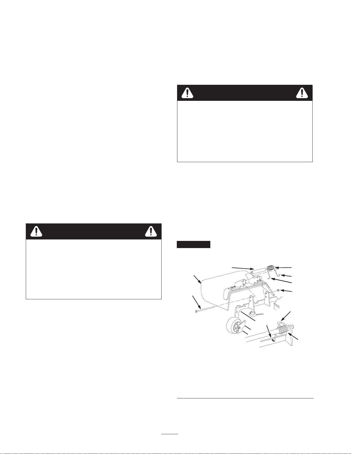
1. Remove the locknut, bolt, spring and spacer holding the
deflector to the pivot brackets (Fig. 50). Remove
damaged or worn grass deflector.
2. Place spacer and spring onto grass deflector. Place the L
end of spring behind deck edge.
Note: Make sure the L end of spring is installed behind
deck edge before installing the bolt as shown in figure 50.
3. Install bolt and nut. Place J hook end of spring around
grass deflector (Fig. 50).
If you operate mower without the bagger installed
or with the discharge tubes and boot removed, you
and others may be injured by thrown debris or cut
by the blade.
• Always operate the mower with either the
complete bagger mounted in place or use the
mower in side discharge.
1. Disengage the power take off (PTO), set the parking
brake, turn the ignition key to off and remove the key.
2. Remove the discharge tubes. Refer to removing The
Discharge Tubes on page 28.
3. Remove hairpin cotters and clevis pins from the bagger
and bagger bracket (Fig. 24).
4. Remove the skid plate (Fig. 26).
5. Remove the bagger belt and bagger tensioner pulley
(Fig. 28).
6. Remove the bagger from the bagger mounting bracket
(Fig. 24).
7. Install the skid plate (Fig. 26).
Important The grass deflector must be able to lower
down into position. Lift the deflector up to test that it
lowers into the full down position.
6
1
m–6846
1. Bolt
2. Spacer
3. Locknut
4. Spring
5. Spring installed
2
7
Figure 50
6. Grass Deflector
7. L end of spring, place
behind deck edge before
installing bolt
8. J hook end of spring
4
8
7
3
8
5
28
Page 29

Operating and Bagging Tips
Machine Size
Remember that the machine is longer and wider with this
attachment installed. By turning too sharply in confined
places you may damage the attachment or other property.
Bagging Long Grass
Excessively long grass is heavy and may not be propelled
completely into the bagger. If this happens, the tube and
boot may plug. To avoid plugging the bagging system,
mow the grass at a high height-of-cut, then lower the
mower to your normal cutting height and repeat the
bagging process.
Trimming
Always trim with the left side of the mower. Do not trim
with the right side of the mower because you could damage
the bagging tubes.
Cutting Height
For optimum bagging performance, set the deck
height–of–cut to remove no more that 2 to 3 inches (51 to
76 mm) or 1/3 of the grass height, which ever is less.
Cutting off more than this will reduce the capacity of the
vacuum system.
Cutting Frequency
Cut the grass often, especially when it grows rapidly. You
will have to cut your grass twice if it gets excessively long
(refer to Bagging Long Grass, page 29).
Cutting Technique
For best lawn appearance, be sure to slightly overlap the
mower into the previously cut area. This helps reduce the
load on the engine and reduces the chance of plugging the
boot and tube.
Bagging Speed
The bagging system may plug if you drive too fast and the
engine speed gets too slow. On hills it may be necessary to
slow the machines ground speed. Mow down hill whenever
possible.
Bagging Wet Grass
If possible, always try to cut grass when it is dry.
Signs of Plugging
As you are bagging, a small amount of grass clippings
normally blow out the front of the mower. An excessive
amount of clipping blow-out indicates that the bagger is
full or the boot is plugged.
Warning
Without the grass deflector, bagger tubes or
complete bagger assembly mounted in place, you
and others are exposed to blade contact and
thrown debris. Contact with the rotating mower
blade(s) and thrown debris will cause injury or
death.
• Never remove the grass deflector from the
mower because the grass deflector routes
material down toward the turf. If the grass
deflector is ever damaged, replace it
immediately.
• Never put your hands or feet under the mower.
• Never try to clear the discharge area or mower
blades unless you move the power take off
(PTO) to off and rotate the ignition key to off.
Also remove the key and pull the wire off of the
spark plug(s).
Caution
As the bagger fills, extra weight is added to the
back of the machine. If you stop and start
suddenly on hills, you may lose steering control or
the machine may tip.
• Do not start or stop suddenly when going uphill
or downhill. Avoid uphill starts.
• If you do stop the machine when going uphill,
disengage the PTO. Then back down the hill
using a slow speed.
• Do not change speeds or stop on slopes.
Fan Vacuum
The bagging system operates by vacuum created by a
rotating fan mounted in the top of the hopper. If the vacuum
action is reduced, bagging performance will diminish.
Refer to Troubleshooting on page 32 for causes of reduced
performance.
Curb Climbing and Loading
Always lift the deck to the highest position when loading
the machine on trailers or ascending/descending a curb.
Leaving the mower in a lower position can cause damage to
the mower while loading and going over a curb. If a curb is
29
Page 30
higher than 6 inches (152 mm), cross it at a sharp angle
with the deck fully raised. Use extreme caution when
loading onto a trailer.
Maintenance
Important If the machine is on a slope, chock or block the wheels to prevent the machine from slowly rolling.
Note: Determine the left and right side of the machine from the normal operating position.
Recommended Maintenance Schedule
Maintenance Service
Interval
Each Use • Screens—clean
8 Hours • Bagger—clean
First 10 Hours
40 Hours • Bagger idler arm—grease
100 Hours
Storage Service
Maintenance Procedure
• Bagger—inspect
• Bagger—check belt tension
• Bagger—inspect
• Bagger fan shaft bearings—grease
• Belts—check for wear/cracks
• Bagger—check
• Bagger—clean
Cleaning the Screens
The screens need to be cleaned before each use. In wet
grass they will need to be cleaned more often.
1. Disengage the power take off (PTO), set the parking
brake, turn the ignition key to off and remove the key.
2. Open the bagger and hold the bagger door open. Refer
to Holding the Bagger Door Open on page 27.
3. Clean the debris from the screens.
4. Close the bagger door.
Checking the Bagger Belt
The bagger belt tension needs to be checked after the first
10 hours.
1. Check the belt tension. Refer to Adjusting the Bagger
Belt on page 18.
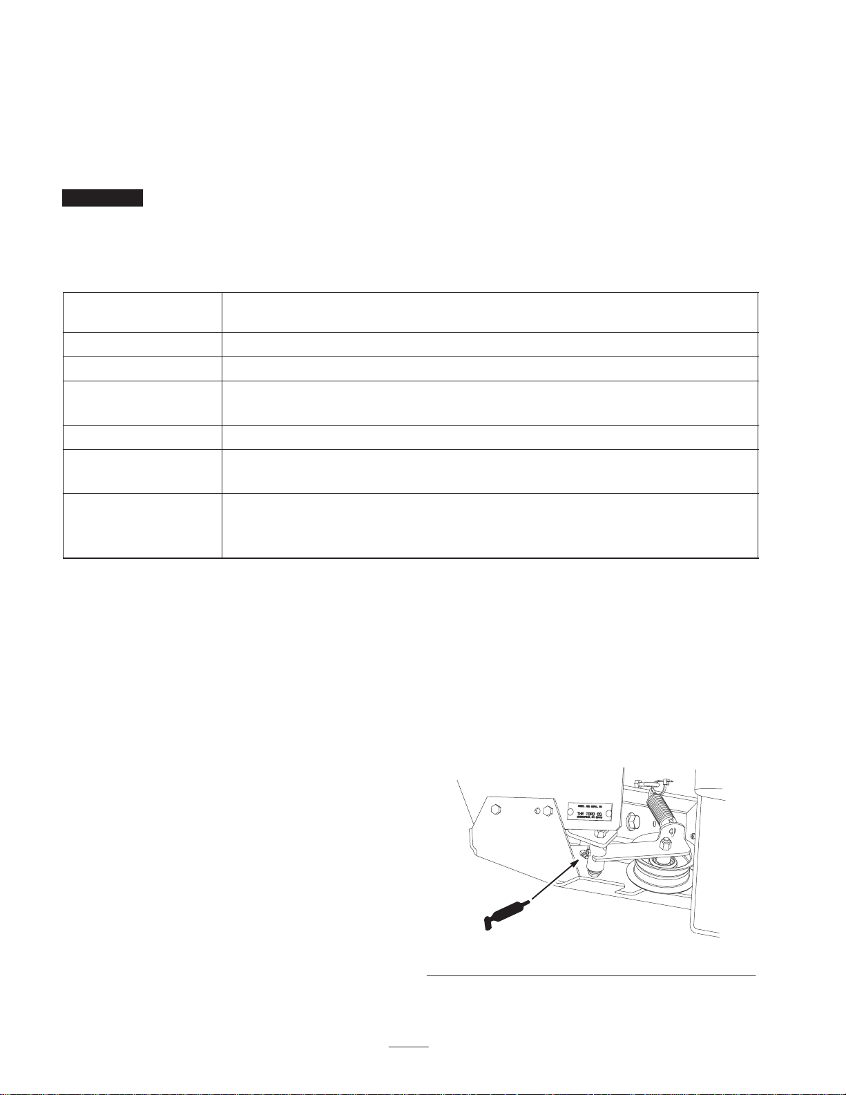
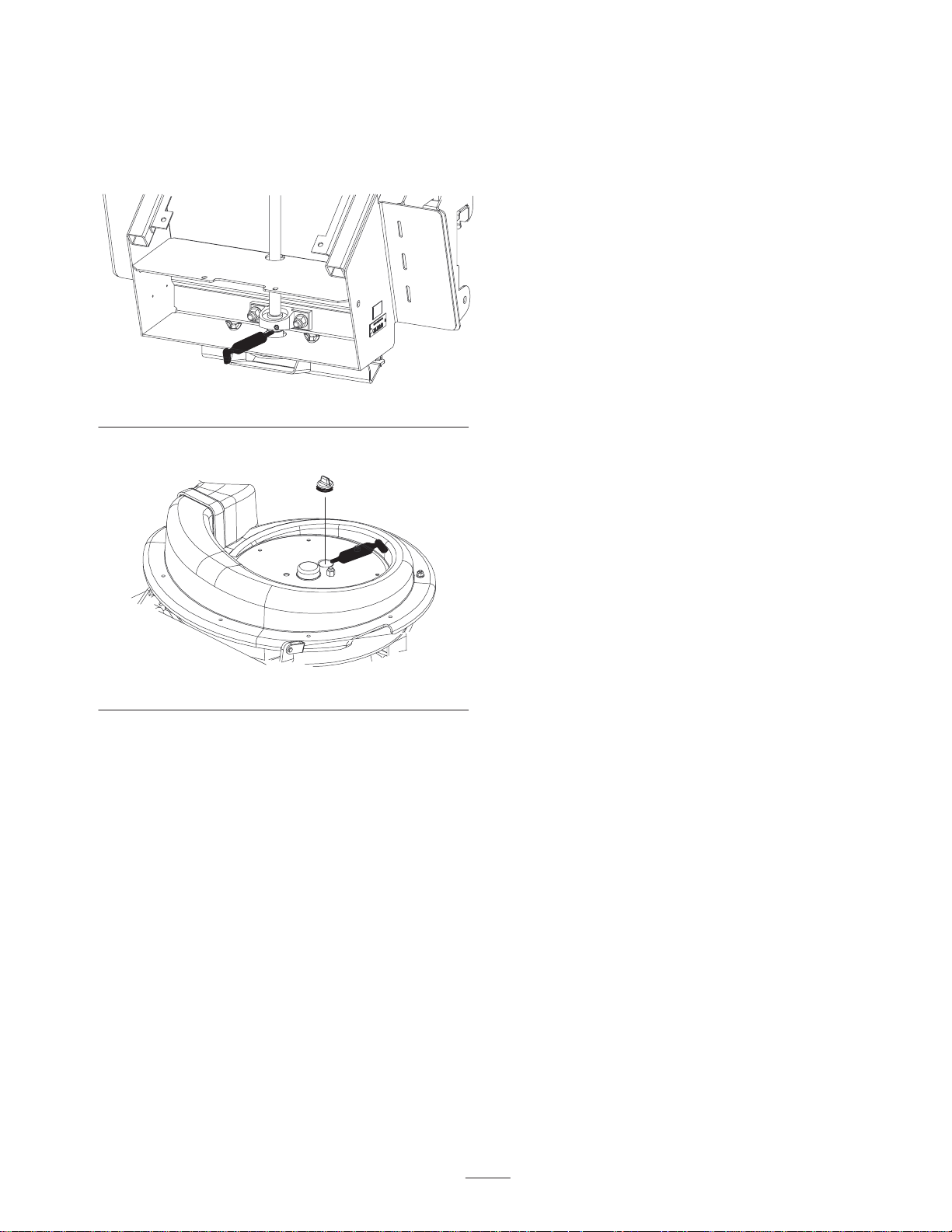
Greasing the Idler Arm
Grease the bagger belt idler arm (Fig. 51) every 40 hours.
Cleaning the Bagger
The bagger needs to be cleaned after every 8 hours.
1. Wash the inside and outside of the bagger, upper tube,
lower tube, boot assembly and the underside of the
mower. Use a mild automotive detergent to remove dirt.
2. Make sure you remove matted grass from all parts.
3. After washing all parts, let them dry thoroughly.
m–6984
Figure 51
30
Page 31
Greasing the Fan Shaft
Inspecting the Mower Blades
Bearings
Grease the upper and lower bagger fan shaft bearings
(Fig. 52 & 53) every 100 hours.
Figure 52
1. Remove rubber plug to expose grease fitting.
1. Inspect the mower blades regularly and whenever a
blade strikes a foreign object.
2. If blades are badly worn or damaged, install new blades.
Refer to your mower operator’s manual for complete
blade maintenance.
Storage
1. Clean the bagger attachment. Refer to Cleaning the
Bagger Attachment on page 30.
2. Inspect the bagger attachment for damage. Refer to
Inspecting the Bagger Attachment on page 30.
3. Make sure the bagger is empty and thoroughly dry.
4. Check the belt for wear or cracks.
5. Store the machine in a clean, dry place, out of direct
sunlight. If you must store the machine outside, cover it
with a weatherproof cover. This protects the plastic
parts and extends the life of the machine.
Figure 53
Inspecting the Bagger
Inspect the bagger attachment after the first ten hours of
operation, and 100 hours thereafter.
1. Disengage the power take off (PTO), set the parking
brake, turn the ignition key to off and remove the key.
2. Check the upper tube, lower tube, and the boot
assembly. Replace these parts if they are cracked or
broken.
3. Check the bagger, bagger frame, and screens. Replace
any parts that are cracked or broken.
4. Tighten all nuts bolts and screws.
31
Page 32

Troubleshooting
gqy
Problem Possible Causes Corrective Action
Abnormal vibration.
Reduced bagging performance.
1. Cutting blade(s) is/are bent or
unbalanced.
2. Blade mounting bolt is loose. 2. Tighten blade mounting bolt.
3. Loose bagger pulley or pulley
assembly.
4. Bagger belt is worn or
damaged.
5. Bagger impeller is out of
balance.
1. Low engine speed. 1. Always operate the bagger at
2. Plugged fan screen. 2. Remove debris, leaves or grass
3. Loose bagger belt. 3. T ighten the bagger belt.
4. Broken seal between hopper
and rear door.
5. A plugged boot. 5. Locate and remove plugged
6. Improper seal around the upper
tube going into the hopper.
1. Install new cutting blade(s).
3. Tighten the appropriate
pulley.
4. Replace the bagger belt.
5. Contact authorized Service
Dealer.
full throttle.
clippings from the fan screen.
4. Ensure the rear door is latched.
debris.
6. Ensure that there is a good
seal at hopper.
Boot and tubes plug too frequently.
Debris blowout.
7. Full hopper. 7. Empty hopper.
1. Hopper is too full. 1. Dump more frequently.
2. Low engine speed. 2. Always operate the bagger at
full throttle.
3. Grass is too wet. 3. Cut grass when dry.
4. Grass is too long. 4. Cut no more that 2–3 inches or
1/3 of the grass height, which
ever is less.
5. Plugged fan screen. 5. Remove debris, leaves or grass
clippings from the fan screen.
6. Ground speed is too fast. 6. Drive slower at full throttle.
1. Hopper is too full. 1. Dump more frequently.
2. Ground speed is too fast. 2. Drive slower at full throttle.
3. Mower is not leveled. 3. See the mower operator’s
manual for leveling the mower.
32
Page 33

33
Page 34
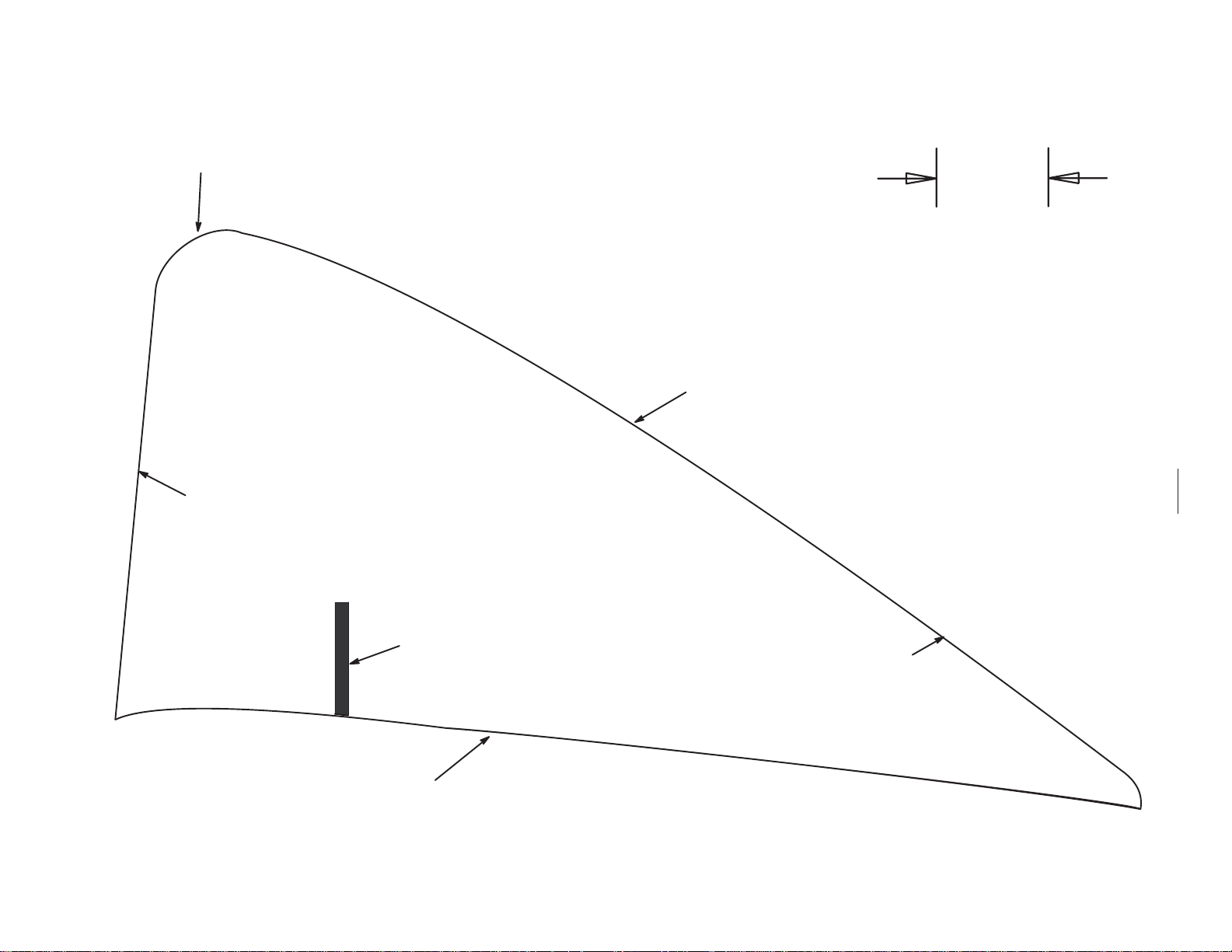
Do Not cut out to
sharp point. Cut with a
radius as shown.
Template No. 1
Scale
Cut the engine shroud
along this edge.
Use this for liquid
cooled engines only.
Template No. 1
Line up mark where
handle hits the
engine shroud.
1 inch
26 mm
Cut out template here
34
Cut the engine shroud
along this edge.
Cut out template here
Page 35

35
Page 36

36
 Loading...