

Page 1

Boot and Tube Kit
100 Series Z Master 44 Mowers
Model No. 78492
Set Up
Loose Parts
Note: Use the chart below to verify all parts have been shipped.
Description Qty. Use
Form No. 3327–682
Installation Instructions
Tunnel baffle—rear
Carriage Bolt, 5/16 x 5/8 in.
Bolt—thread forming, 3/8 x 5/8 in.
Flange nuts, 5/16 in.
Tunnel baffle—front
Carriage Bolt, 5/16 x 5/8 in.
Flange nuts, 5/16 in.
Tunnel baffle—center
Carriage Bolt, 5/16 x 5/8 in.
Bolt, 5/16 x 5/8 in.
Flange nuts, 5/16 in.
Cutting chamber baffle
Socket button head bolt, 1/4 x 5/8 in.
Lock nuts, 1/4 in.
Socket button head bolt, 5/16 x 3/4 in.
Flange nuts, 5/16 in.
Lower bagger tube
Upper bagger tube
Boot assembly
Tube clamp
1
3
1
3
1
2
2
1
2
1
3
1
2
2
3
3
1
1
1
1
Installing the rear tunnel baffle
Installing the front tunnel baffle
Installing the center tunnel baffle
Installing the cutting chamber baffle
Installing the discharge tubes
Note: If the mower is removed from the machine, it will
need to be leveled when installed.
Removing the Mower
1. Lower the mower onto wood blocks.
2002 by The Toro Company
8111 Lyndale Avenue South
Bloomington, MN 55420-1196
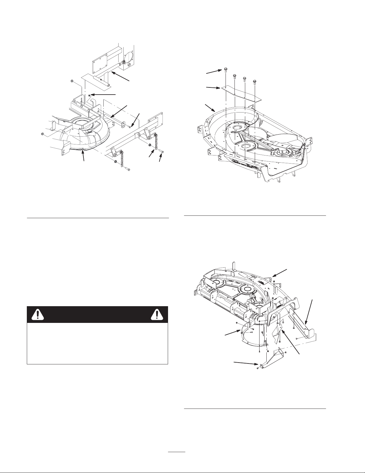
2. Remove the four bolts at the bottom of chains that
attached to mower (Fig. 1).
3. Remove the nuts and bolts holding pins in the push
arm (Fig. 1).
4. Remove the pins (Fig. 1).
5. Raise height of cut lever and slide mower out (Fig. 1).
All Rights Reserved
1
Printed in the USA
Page 2
6. Remove the mower belt from the clutch.
6
1. Remove the four screws holding the right front
blowout baffle to the mower (Fig. 2).
2. Remove the baffle (Fig. 2). Save the baffle and screws
for use when not in bagging mode.
2
4
7
1
3
5
m–6062
1
Figure 1
2
1. Mower
2. Chain
3. Chain Bolt
4. Push Arm
5. Push Arm Bolt
6. Push Arm Nut
7. Push Arm Pin
Before Installation
1. Tip mower upside down and block up ends to ease
installation of components.
2. Thoroughly clean the mower. All debris must be
removed to ensure baffles will fit properly against the
mower.
3. Repair all bent or damaged areas of mower and
replace any missing parts.
Warning
Contact with sharp blade can cause serious
personal injury.
3
m–6069
Figure 2
1. Right front blowout baffle
2. Screw
3. Mower
Installing the Mower Baffles
Note: Use figure 3 for an overall view of where to install
the baffles.
3
1
5
• Wear gloves or wrap sharp edges of the
blade with a rag.
Removing the Right Front
Blowout Baffle
Note: Remember to install the right front blowout baffle
to the mower if the bagger and bagger baffles are
removed.
1. Front tunnel baffle
2. Rear tunnel baffle
3. Front of mower
2
4
2
m–6058
Figure 3
4. Center tunnel baffle
5. Cutting chamber baffle
Page 3

Installing the Front Tunnel
Baffle
1
2
1. Place the front tunnel baffle against the front wall of
the discharge tunnel (Fig. 5).
2. Align the front tunnel baffle flush with the outside of
the mounting bracket (Fig. 4).
1
3
m–5930
Figure 4
1. Front tunnel baffle
2. Mounting bracket
3. Flush edge with outside of
mounting bracket
4. Outside of mounting
bracket
3. Clamp the baffle in place.
4. Using the baffle as a template, drill two, 11/32 in.
diameter, holes into the top of the discharge tunnel
(Fig. 5).
5. Install the front tunnel baffle with 2 carriage bolts
(5/16 x 5/8 in.) and 2 flange nuts (5/16 in.) (Fig. 5).
4
6
2
4
5
3
m–6045
Figure 5
1. Front tunnel baffle
4
2. Carriage Bolt, 5/16 x
5/8 in.
3. Flange nut, 5/16 in.
4. Hole to drill
5. Mounting bracket
6. Front tunnel wall
Installing the Rear Tunnel
Baffle
Note: There is an existing hole in the top of the mower for
installing the rear tunnel baffle.
1. Place the rear tunnel baffle against the rear wall of the
discharge tunnel. (Fig. 6).
2. Loosely, install the thread forming bolt (3/8 x 5/8 in.)
into the existing hole in the top of the mower (Fig. 8).
Note: The rear tunnel baffle must not extend past the
outside of the mounting bracket.
3. Slide the rear tunnel baffle along the rear wall until
there is a 3/16 in. gap between the blade and the baffle
tab (Fig. 7).
3
Page 4

2
6
2
9
3
3
4
1
7
5
1
5
m–6046
Figure 7
1. Rear tunnel baf fle
2. 3/16 in. gap
3. Blade
4. Baffle tab
5. Tunnel rear wall
4. Tighten the thread forming bolt (3/8 x 5/8 in.) into the
top of the mower (Fig. 8).
5. Clamp the baffle in place.
6. Using the baffle as a template, drill two, 11/32 in.
diameter, holes into the top of the discharge tunnel
(Fig. 8).
7. Drill one, 11/32 in. diameter, hole into the rear wall of
the discharge tunnel (Fig. 8).
8. Remove the clamp.
9. Install the rear tunnel baffle with 3 carriage bolts
(5/16 x 5/8 in.) and 3 flange nuts (5/16 in.) (Fig. 8).
Important Make sure the bolt heads are installed on
the inside of the cutting chamber.
4
3
4
m–5925
2
8
Figure 8
1. Rear tunnel baffle
2. Carriage Bolt, 5/16 x
5/8 in.
3. Flange nut, 5/16 in.
4. Hole to drill
5. Existing hole
6. Baffle tab
7. Rear wall of the discharge
tunnel
8. Outside of mounting
bracket
9. Thread forming bolt, 3/8 x
5/8 in.
Installing the Center Tunnel
Baffle
Important Do not install this baffle when bagging
grass unless blowout is a problem. This baffle is highly
recommended when bagging leaves.
Note: Remove this baffle once the cutting chamber baffle
is installed.
1. Place the center tunnel baffle between the front and
rear tunnel baffles (Fig. 9).
2. Install the center tunnel baffle to the front tunnel
baffle. The flange on the center baffle goes over and
behind the front baffle (Fig. 9).
3. Secure the center tunnel baffle with two carriage bolts
(5/16 x 5/8 in.) and flange nuts (5/16 in.) (Fig. 9).
1
Note: There is an existing hole for installing the center
baffle to the rear wall.
4
Page 5

4. Install the center tunnel baffle to the rear wall of the
7
7
discharge tunnel. Use a bolt (5/16 x 5/8 in.) and flange
nut (5/16 in.) (Fig. 9).
2
5
4
6
2
3
m–5930
Figure 9
1. Center tunnel baffle
2. Bolt, 5/16 x 5/8 in.
3. Flange nut, 5/16 in.
4. Flush edge
5. Front tunnel baffle
6. Existing hole
1
3
1. Baffle flange
2. Blade
3. Spindle
Figure 10
1
54 32
4. Blade clearance,
5/8 in. ±1/16 in.
5. Baffle to top of cutting
chamber, 4–1/8 in.
1
2
m–608
3
4
Installing the Cutting Chamber
Baffle
Note: There are two existing holes in the mower flange
for installing the cutting chamber baffle.
1. Place the cutting chamber baffle behind the right
cutting blade chamber and against the mower flange
(Fig. 12).
2. Install the cutting chamber baffle to the mower flange
with 2 socket button head bolts (1/4 x 5/8 in.) and 2
locknuts (1/4 in.) (Fig. 12).
3. Align the cutting chamber baffle so the baffle flange is
4–1/8 in. (92 mm) from the top of the cutting chamber
(Figures 10 and 11).
Important Make sure the baffle flange is 4–1/8 in.
(92 mm) from the top of the cutting chamber and there is
blade clearance of 5/8 in. ±1/16 in. (Figures 10 and 11).
m–606
Figure 11
1. Baffle flange
2. Blade
3. Spindle
4. Baffle to top of cutting
chamber, 4–1/8 in.
4. Clamp the cutting chamber baffle in place (Fig. 11).
5. Using the baffle as a template, drill two 11/32 in.
diameter, holes into the side of the cutting chamber
(Fig. 12).
6. Drill one, 11/32 in. diameter, hole into the back of the
mower (Fig. 13).
7. Remove the clamp.
8. Install the cutting chamber baffle to the back side of
the cutting chamber with 2 socket button head bolts
(5/16 x 3/4 in.) and 2 flange nuts (5/16 in.) (Fig. 12).
5
Page 6

3
7
5
1
1
4
2
2
9
4
9 6
Figure 12
1. Cutting chamber baffle
2. Holes to drill
3. Flange nuts, 5/16 in.
4. Socket button head bolt,
5/16 x 3/4 in.
5. Socket button head bolt,
1/4 x 5/8 in.
6. Lock nut, 1/4 in.
7. Baffle flange
8. Mower flange
9. Existing hole
9. Install the cutting chamber baffle to the back of the
mower with a socket button head bolt (5/16 x 3/4 in.)
and a flange nut (5/16 in.) (Fig. 13).
6
8
m–6055
4
5
2
6
7
3
m–6083
Figure 13
1. Cutting chamber baffle
2. Hole to drill
3. Right–hand cutting blade
chamber
4. Flange nut, 5/16 in.
5. Socket button head bolt,
5/16 x 3/4 in.
6. Mower flange
7. Back of mower
Important Make sure the bolt heads are installed on
the inside of the cutting chamber.
10.Rotate the blades to ensure there is clearance between
the blade tips and the baffles, as specified in figure 10.
11. If contact is made, do not use the mower. Check and
make sure all baffles are installed properly.
Installing the Discharge Tubes
Refer to the bagger operator ’s manual for installing the
discharge tubes.
Installing the Blades
Note: In certain mowing conditions, improved bagging
performance can be achieved by using bagging blades.
Contact an Authorized Service Dealer for the proper
blades for different mowing conditions.
6
Page 7

Warning
Contact with sharp blade can cause serious
personal injury.
• Wear gloves or wrap sharp edges of the
blade with a rag.
1. Install the bagging blade onto the spindle shaft
(Fig. 14).
Important The curved part of the blade must be
pointing upward toward the inside of the mower to ensure
proper cutting.
2. Install the flat washer, lock washer and blade bolt
(Fig. 14). Torque the blade bolt to 85–110 ft.-lb.
(115–150 Nm).
3. Rotate the blades to ensure there is clearance between
the blade tips and the baffles.
4. If contact is made, do not use the mower. Check and
make sure the baffles are installed properly.
Important Do not use the mower if blades contact the
baffles.
1
2
4
3
5
m–4318
Figure 14
1. Sail area of blade
2. Blade
3. Flat washer
4. Blade bolt
5. Split lockwasher
Installing the Mower
1. Install the mower to the machine. Reverse the
instructions in Removing the Mower on page 1.
Note: The mower will need to be leveled when installed.
Refer to your operator’s manual.
2. Install the mower belt after the bagger is installed.
7
Page 8

8
 Loading...