

Toro 78490 Parts Catalogue

Bagger
Z Master 100 Series
Model No. 78490—220000501 and Up
Form No. 3328-156
Parts Catalog
Ordering Replacement Parts
To order replacement parts, please supply: the part
number, the quantity, and the description of each
part desired.
Understanding Reference Numbers
Each identified part in an illustration has a reference
number. The reference number for a part also appears in
the parts list, along with other information about the part.
This catalog uses two special reference number formats,
one to indicate parts in a service assembly and another
to indicate the quantity of a given part in an illustration.
Service Assembly Reference Numbers
Parts in service assemblies have reference numbers in
the form a:b.
the entire service assembly and the b represents a
sequential number unique to each part within the service
assembly.
The a represents the reference number of
The TORO Company — 2002
All Rights Reserved
For example, a wheel assembly might be identified by
reference number 6, the tire by 6:1, the valve by 6:2,
and the wheel by 6:3. When you order the assembly
identified by reference number 6, you receive all parts
identified by reference numbers 6:1, 6:2, and 6:3.
However, you may also order any part individually.
Reference numbers of this type appear in illustrations
and in part lists.
Reference Numbers Indicating Quantity
In an illustration, if a reference number indicates more
than one part, the reference number has the form nX y.
The n represents the quantity of the part, the X is the
multiplication symbol, and the y represents the reference
number.
For example, in an illustration, the reference number
2X 37 means that two of the parts identified by reference
number 37 are indicated.

3328–156
Contents
Description Page Description Page
Door Assembly 3. . . . . . . . . . . . . . . . . . . . . . . . . . . .
Hopper Frame Assembly 4. . . . . . . . . . . . . . . . . . .
Hopper Assembly 5. . . . . . . . . . . . . . . . . . . . . . . . .
Impeller and Scroll Assembly 6. . . . . . . . . . . . . . .
Dump Lever Assembly 7. . . . . . . . . . . . . . . . . . . . .
Bagger Mounting Frame and Fan Drive Idler
Assembly 8. . . . . . . . . . . . . . . . . . . . . . . . . . . . . .
Weight Assembly 9. . . . . . . . . . . . . . . . . . . . . . . . . .
Part Description Abbreviations
Part descriptions in this catalog may include the following abbreviations.
Abbreviation Meaning Abbreviation Meaning
AR as required. . . . . . . . . . . . . . . . .
ASM assembly. . . . . . . . . . . . . . . .
CARR carriage. . . . . . . . . . . . . .
DEG degrees. . . . . . . . . . . . . . . .
FH flat head. . . . . . . . . . . . . . . . .
GA gauge. . . . . . . . . . . . . . . . .
HF hex flange. . . . . . . . . . . . . . . . .
HH hex head. . . . . . . . . . . . . . . . .
HHF hex head flange. . . . . . . . . . . . . . . .
HLH hex lag head. . . . . . . . . . . . . . . .
HJ hex jam. . . . . . . . . . . . . . . . . .
HOC height-of-cut. . . . . . . . . . . . . . . .
HS hex socket. . . . . . . . . . . . . . . . .
HSBH hex socket button head. . . . . . . . . . . . . .
HSFH hex socket flat head. . . . . . . . . . . . . . .
HSH hex socket head. . . . . . . . . . . . . . . .
HWH hex washer head. . . . . . . . . . . . . . .
HWHTF hex washer head. . . . . . . . . . . . .
thread forming
HYD hydraulic. . . . . . . . . . . . . . . .
INC incorporated. . . . . . . . . . . . . . . . .
LH left hand. . . . . . . . . . . . . . . . .
NI nylon insert. . . . . . . . . . . . . . . . . .
PPH Phillips pan head. . . . . . . . . . . . . . . .
PTH Phillips truss head. . . . . . . . . . . . . . . .
PTO power take off. . . . . . . . . . . . . . . .
RH right hand. . . . . . . . . . . . . . . . .
SFH slotted fillister head. . . . . . . . . . . . . . . .
SHH slotted hex head. . . . . . . . . . . . . . . .
SQH square head. . . . . . . . . . . . . . . .
SHWH slotted hex washer head. . . . . . . . . . . . . .
SPH slotted pan head. . . . . . . . . . . . . . . .
SRH slotted round head. . . . . . . . . . . . . . . .
STD standard. . . . . . . . . . . . . . . .
TAP self tapping. . . . . . . . . . . . . . . .
TTH Torx truss head. . . . . . . . . . . . . . . .
WH wing head. . . . . . . . . . . . . . . . .
2
13
15
14
3328–156
1
2
3
5:2
5
2
9
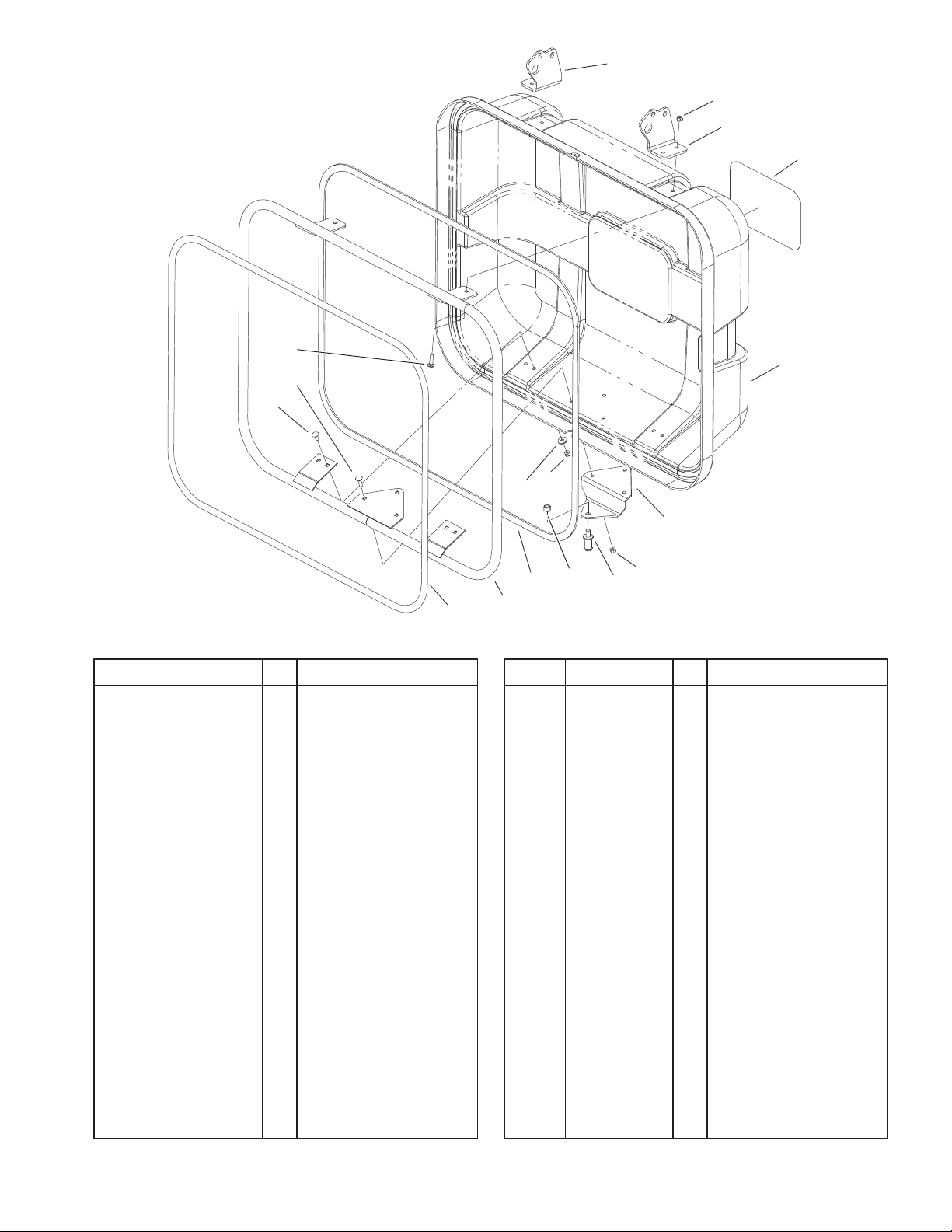
Door Assembly
DescriptionPart No. Qty.Ref. No. DescriptionPart No. Qty.Ref. No.
1 105–8248–03 1 Bracket–Hinge, RH
2 3296–29 11 Nut–Lock, NI
3 105–8249–03 1 Bracket–Hinge, LH
5 106–5478 1 Door ASM
5:2 67–7310 1 Decal–Toro
5:3 105–8198 1 Seal–Hopper
6 105–8238–03 1 Bracket–Latch, Door
7 105–9664 1 Bolt–Striker
8 3296–48 1 Nut–Lock NI
9 3256–82 4 Washer–Flat
11 106–5479 1 Frame ASM
11:2 105–8199 1 Seal–Hopper, Round
13 3230–16 4 Screw–CARR
14 3230–2 3 Screw–CARR
15 3230–3 4 Screw–CARR
11:2
11
5:3
6
8
2
7
Sheet No.:2
3
3328–156
2
1
3
27
16
19
18
17
22
17
10
21
17
16
15
14
10
11
12
13
10
17
28
4
23
25
24
20
8
9
26
33
34
17
33
32
29
31
Sheet No.:3
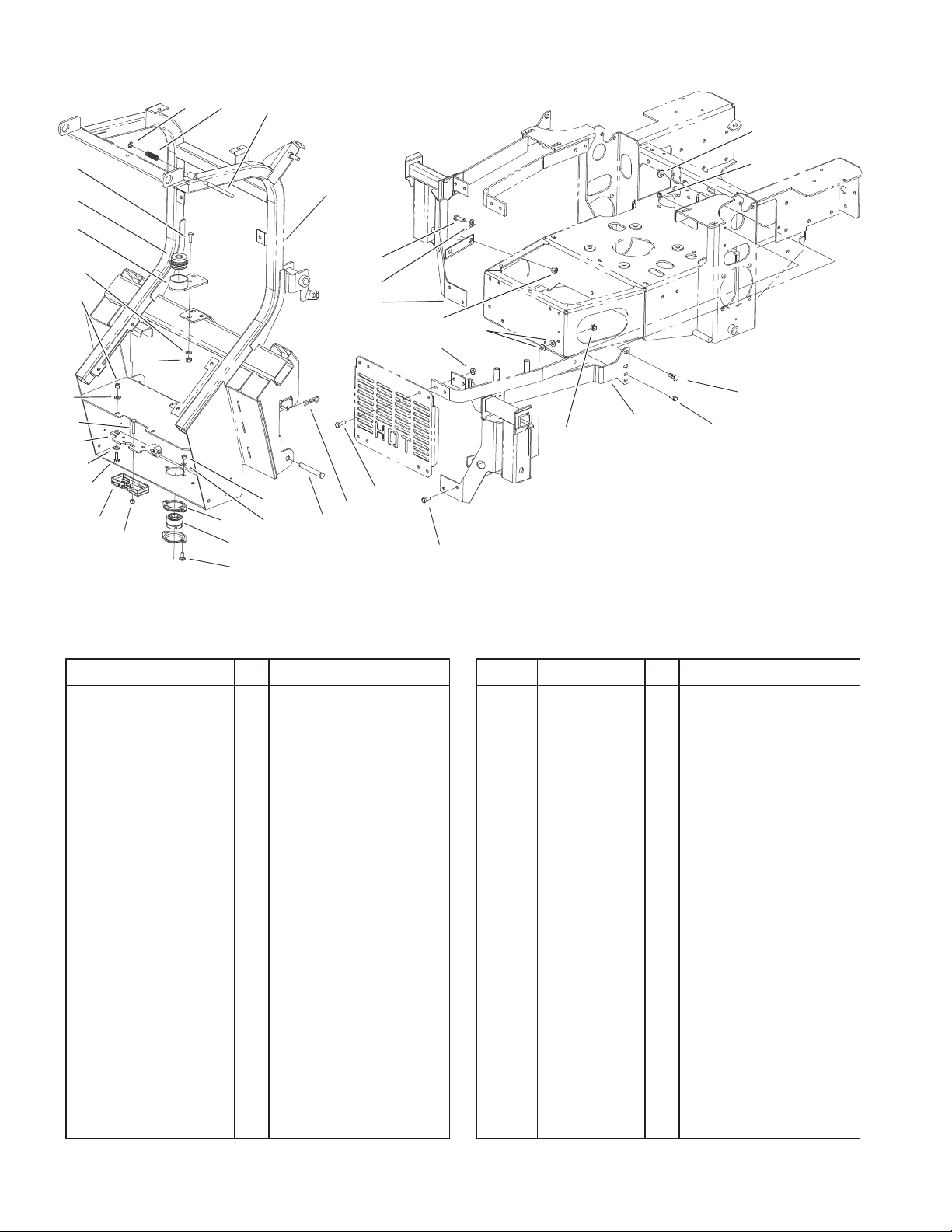
Hopper Frame Assembly
DescriptionPart No. Qty.Ref. No. DescriptionPart No. Qty.Ref. No.
1 32151–101 1 E–Ring
2 105–9715 1 Spring
3 105–5574 1 Hook
4 105–9650–03 1 Frame ASM
8 1–806005 2 Pin–Hair
9 283–69 2 Pin–Clevis
10 3296–29 7 Nut–Lock, NI
11 105–9714 2 Flange–Bearing
12 105–9669 1 Bearing–Spherical
13 3230–1 2 Screw–CARR
14 3296–42 4 Nut–Lock, NI
15 105–9663 1 Latch–Rotor
16 322–4 5 Screw–HH
17 3256–23 17 Washer–Flat
18 105–9697–03 1 Bearing Flange ASM
19 105–9670 1 Bearing–Cylindrical
20 322–5 4 Screw–HH
21 105–8237 1 Bracket–Latch
22 321–9 4 Screw–HH
23 323–6 4 Screw–HH
24 106–3332–03 1 LH Bagger Mount ASM
25 3256–24 4 Washer–Flat
26 3296–39 4 Nut–Lock, NI
27 32128–19 4 Nut–HF
28 32128–33 2 Nut–HF
29 3231–27 4 Screw–CARR
31 321–4 2 Screw–HH
32 106–3331–03 1 RH Bagger Mount
ASM
33 32128–20 8 Nut–HF
34 322–3 4 Screw–HH
4
 Loading...