

Page 1

48in Side Discharge Mower
for 5xi Garden Tractors
Model No. 78449—Serial No. 230000001 and Up
Form No. 3326-570
Operator ’s Manual
Original Instructions (GB)
Page 2
Contents
Page
Introduction 2. . . . . . . . . . . . . . . . . . . . . . . . . . . . . . . .
Safety and Instruction Decals 3. . . . . . . . . . . . . . . . . . .
Setup 4. . . . . . . . . . . . . . . . . . . . . . . . . . . . . . . . . . . . .
Loose Parts 4. . . . . . . . . . . . . . . . . . . . . . . . . . . . . .
Assembling the Mower 4. . . . . . . . . . . . . . . . . . . . .
Installing the Mower 5. . . . . . . . . . . . . . . . . . . . . .
Attaching the PTO Drive Belt 7. . . . . . . . . . . . . . .
Adjusting the Mower 8. . . . . . . . . . . . . . . . . . . . . .
Removing the Mower 11. . . . . . . . . . . . . . . . . . . . . .
Operation 12. . . . . . . . . . . . . . . . . . . . . . . . . . . . . . . . . .
Operating the Mower 13. . . . . . . . . . . . . . . . . . . . . .
Cutting Modes 13. . . . . . . . . . . . . . . . . . . . . . . . . . .
Adjusting the Front Wheels 13. . . . . . . . . . . . . . . . .
Check for Debris 13. . . . . . . . . . . . . . . . . . . . . . . . .
Tips for Mowing Grass 13. . . . . . . . . . . . . . . . . . . . .
Maintenance 14. . . . . . . . . . . . . . . . . . . . . . . . . . . . . . . .
Recommended Maintenance Schedule 14. . . . . . . . .
Servicing the Blades 15. . . . . . . . . . . . . . . . . . . . . . .
Greasing the Blade Spindles 16. . . . . . . . . . . . . . . . .
Checking PTO Drive Belt Tension 16. . . . . . . . . . . .
Extending PTO Drive Belt Life 17. . . . . . . . . . . . . .
Replacing the Blade Drive Belt 17. . . . . . . . . . . . . .
Washing the Mower 17. . . . . . . . . . . . . . . . . . . . . . .
Storage 18. . . . . . . . . . . . . . . . . . . . . . . . . . . . . . . . . . . .
Troubleshooting 19. . . . . . . . . . . . . . . . . . . . . . . . . . . . .
Introduction
Read this manual carefully to learn how to operate and
maintain your product properly. The information in this
manual can help you and others avoid injury and product
damage. Although Toro designs and produces safe
products, you are responsible for operating the product
properly and safely.
Whenever you need service, genuine Toro parts, or
additional information, contact an Authorized Service
Dealer or Toro Customer Service and have the model and
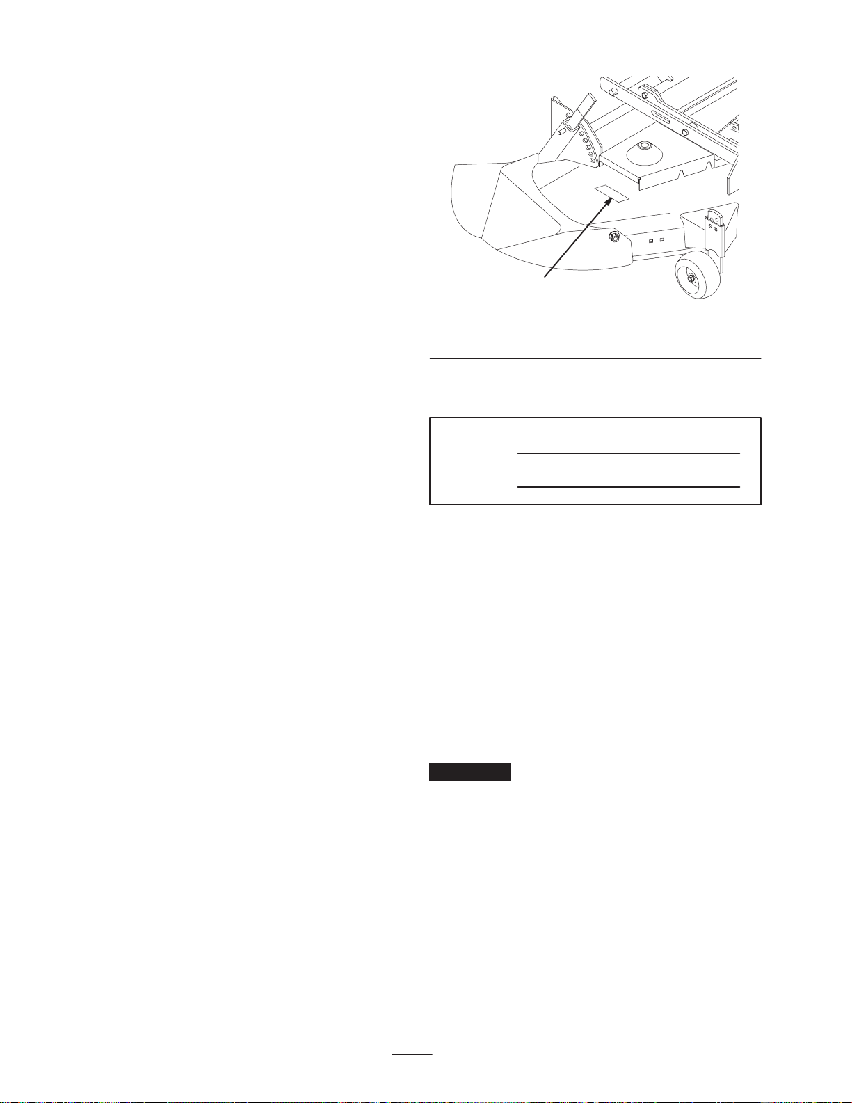
serial numbers of your product ready. Figure 1 illustrates
the location of the model and serial numbers on the
product.
1
Figure 1
1. Location of the model and serial numbers
Write the product model and serial numbers in the space
below:
Model No.
Serial No.
This manual identifies potential hazards and has special
safety messages that help you and others avoid personal
injury and even death. Danger, Warning, and Caution are
signal words used to identify the level of hazard. However,
regardless of the hazard, be extremely careful.
Danger signals an extreme hazard that will cause serious
injury or death if you do not follow the recommended
precautions.
Warning signals a hazard that may cause serious injury or
death if you do not follow the recommended precautions.
Caution signals a hazard that may cause minor or moderate
injury if you do not follow the recommended precautions.
This manual uses two other words to highlight information.
Important calls attention to special mechanical
information and Note: emphasizes general information
worthy of special attention.
m-3520
2003 by The Toro Company
8111 Lyndale Avenue South
Bloomington, MN 55420-1196
All Rights Reserved
Printed in the USA
2
Page 3
Safety and Instruction Decals
This machine meets or exceeds the EN 836-1997 and ISO 5395-2001 specifications in effect at the time of production.
However, improper use or maintenance by the operator or owner can result in injury. To reduce the potential for
injury, comply with these safety instructions and always pay attention to the safety alert symbol, which means
CAUTION, WARNING, or DANGER—“personal safety instruction.” Failure to comply with the instruction may
result in personal injury or death. Refer to your tractor Operator’s Manual for additional safety instructions.
Safety decals and instructions are easily visible to the operator and are located near any area
of potential danger. Replace any decal that is damaged or lost.
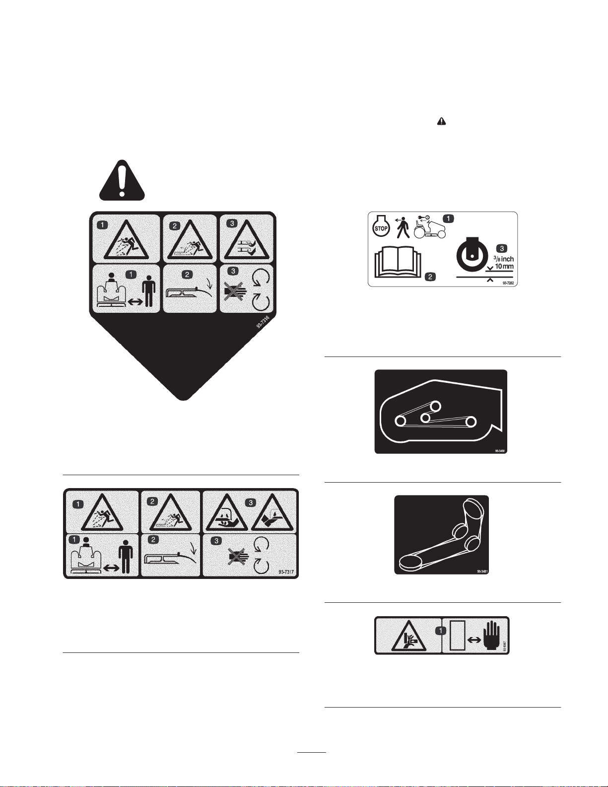
93-7282
1. Stop the engine and
remove the ignition key
before leaving the
machine
2. Read the
Manual.
3. Wheel height
Operator’s
93-7316
1. Thrown object hazard—stay a safe distance from the machine.
2. Thrown object hazard, mower—keep the deflector in place.
3. Cutting/dismemberment of hand or foot—stay away from
moving parts.
93-7317
1. Thrown object hazard—stay a safe distance from the machine.
2. Thrown object hazard, mower—keep the deflector in place.
3. Cutting/dismemberment of hand or foot—stay away from
moving parts.
98-3480
98-3481
93-9367
1. Crushing hazard of hand—keep hands a safe distance from
the hazard area.
3
Page 4
Setup
Note: Determine the left and right sides of the machine from the normal operating position.
Loose Parts
Note: Use the chart below to identify parts used for assembly.
Description Qty. Use
Discharge chute
Nylon washer, 3/8 in.
Spring
Rubber bushing
Flat washer, 1/2 in.
Locknut, 3/8 in.
Cotter pin, 3/4 in.
Pulley box
PTO drive belt
Assembling the Mower
Installing the Discharge Chute
1. Place the short end of the spring into the small hole in
the discharge chute (Fig. 2).
1
4
2
9
1
2
1
1
1
1
1
1
1
3
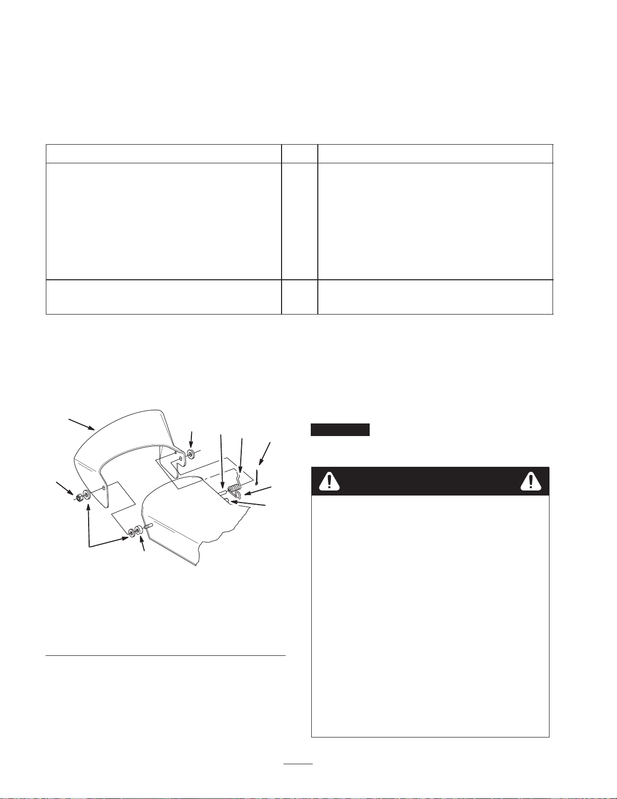
Install the discharge chute
Install the PTO drive belt
4. Slide the rubber bushing and nylon washer over the stud
at the front of the mower.
5. Place the discharge chute over the stud and secure it
with a second nylon washer and a locknut (3/8 in.)
(Fig. 2).
6. Tighten the locknut flush with the end of the stud.
Important The discharge chute must be spring loaded
in the down position. Lift the chute up and release it to test
that it snaps to the full down position.
7
6
1. Discharge chute
2. Spring
3. Cotter pin, 3/4 in.
4. Washer, 1/2 in.
5. Rubber bushing
2. Position the spring and discharge chute over the post on
the rear of the mower and secure them with a washer
(1/2 in.) and a cotter pin (3/4 in.) (Fig. 2).
3. Ensure that the loop in the spring slides over the stud on
the mower housing.
5
Figure 2
6. Plastic washer
7. Jam nut, 3/8 in.
8. Loop in spring
9. Post on mower housing
10. Stud on mower housing
8
10
m-3144
Danger
Without the grass deflector, discharge cover, or
complete grass catcher assembly mounted in place,
you and others are exposed to blade contact and
thrown debris. Contact with the rotating mower
blades and thrown debris will cause injury or
death.
• Never remove the grass deflector from the
mower because the grass deflector routes
material down toward the turf. If the grass
deflector is ever damaged, replace it
immediately.
• Never put your hands or feet under the mower.
• Never try to clear the discharge area or mower
blades unless you move the power take off
(PTO) to Off and rotate the ignition key to Off.
Also remove the key and pull the wires off of the
spark plugs.
4
Page 5
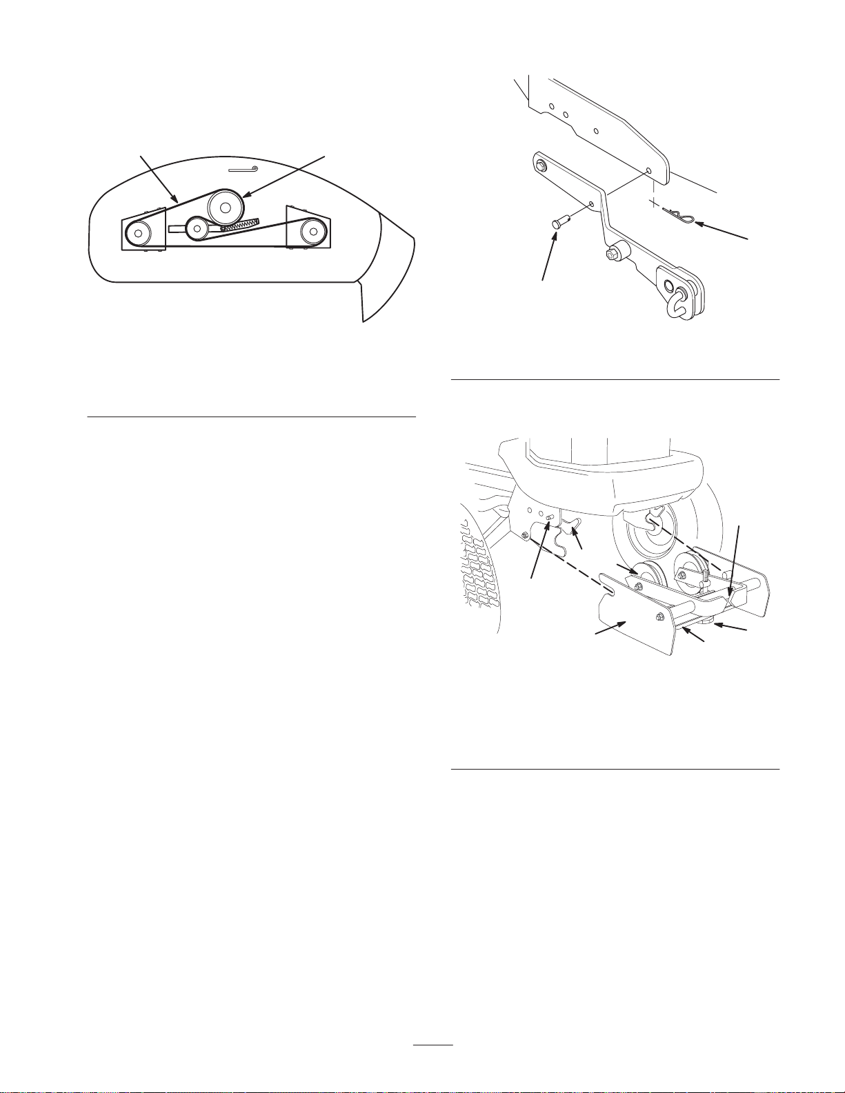
Mower Belt Routing
Route the mower belt as shown in Fig. 3. Ensure that you
install the belt on the lower mower deck pulley.
1
2
m-3525
Figure 3
Top View
1. Mower belt 2. Mower deck pulley
Installing the Mower
Preparing the Tractor
Install the mower on a level concrete surface. Rougher dirt
or lawn surfaces make installation more difficult.
2
1
m–3433
Figure 4
1. Clevis pin 2. Hairpin cotter
4. Attach the pulley box if it is not already on the tractor
(Fig. 5).
6
1. Position the tractor and mower side by side, with the
mower on the right side of the tractor.
2. Set the parking brake, raise the attachment lift, stop the
engine, and remove the ignition key.
3. If you have previously had a snowthrower, blade, or
tiller attached to the attachment lift, remove the two
clevis pins on each side of the attachment lift (Fig. 4).
1
3
7
2
Figure 5
1. Attach-A-Matic latches
2. Pulley box
3. Idler pulley
4. Belt tension release arm
5. Belt tension adjustment
knob
6. Belt tension indicators
7. Attach-A-Matic buttons
(one on each side)
A. Ensure that the latches on the tractor’s front
Attach-A-Matic are open.
B. Slide the pulley box into the Attach-A-Matic
latches and seat it.
C. Close the latches.
4
m–5510
5
5
Page 6
Attaching the Mower
1. Set the mower wheels for the lowest height of cut.
2. Move the attachment lift to the full up position.
3. From the right side of the tractor, slide the mower under
the tractor.
4. Position the mower so that the slots in the side of each
of the mower mounting brackets (Fig. 6) are aligned
directly below the tractor attachment lift arm.
3
2
1
1. Slots in the side mounting
brackets (2)
2. Belt guide
Figure 6
3. Front to rear adjustment
rod
m–3519
1
2
m–3456
Figure 7
Left Side of Tractor Shown
1. J-pin 2. Mower slot in side
mounting bracket.
7. On the left side, pull out the attachment lift J-pin and
slide it into the slot on the other mower mounting
bracket.
8. After the two J-pins are seated through the mower
mounting brackets, using the attachment lift and your
hand on the right front adjustable mower wheel bracket
(Fig. 8), position the mower so its attachment bar fits
into the mid Attach-A-Matic mount.
Caution
5. Start the tractor.
6. Lower the attachment lift arm fully and adjust the
mower position until you can pull out on the J-pin of
the lift arm and slide it into the slot in the mounting
bracket of the mower (Fig. 7).
Movement of the attachment lift between the
mower mounting brackets and the attachment lift
arms can injure a person when aligning the deck
with the lift arms.
• Keep hands away from moving parts while
operating the attachment lift.
• Always position the mower with your hand on
the right front mower wheel bracket.
• Never try to position the mower with your
hands on the mower mounting brackets or
below the mower housing.
6
Page 7

Figure 8
1. Place hand here
9. Turn the lever of the Attach-A-Matic
counterclockwise to lock the mower to the tractor
(Fig. 9).
Caution
Components under the hood will be hot if the
tractor has been running. If you touch hot
components you may be burned.
Allow the tractor to cool before performing
maintenance or touching components under the
hood.
2. Release the belt tension release arm on the pulley box
housing and swing it out toward you (Fig. 10).
m–35211
2
4
5
3
3
1
Figure 10
1. Belt tension release arm
2. Belt tension indicators
3. Belt tension adjustment
knob
4. Seating position for
tension arm
5. Belt tension released
m–5511
1
2
m–3611
Figure 9
1. Attach-A-Matic button
2. Attach-A-Matic lever
3. Lock
10.Set the parking brake, lower the attachment lift, stop the
engine, and remove the ignition key.
Attaching the PTO Drive Belt
1. Remove the tractor grill.
3. Extend the belt through the center of the pulley box,
between the two pulleys.
4. Position the belt into the groove of the PTO pulley
(Fig. 11), making sure it is also under the pulleys in the
pulley box.
2
3
1
m–4231
Figure 11
1. Pulley box pulley
2. PTO pulley
3. PTO drive belt
7
Page 8

5. Hang the belt over the mower, then thread it forward
through the belt guide (Fig. 12) on the mower.
2
D. Swing the tension release arm into the pulley box
and seat it by moving it into the position shown in
Figure 10.
9. Loosen the belt guide bolt (Fig. 14).
2
1
m–3457
Figure 12
1. Belt 2. Belt guide
6. Loop the other end of the belt over the drive pulley of
the mower. Additional belt slack can be obtained (if
needed) by turning the belt tension adjustment knob
(Fig. 10).
7. Make certain that the wide side of the PTO drive belt is
toward the outside diameter of all (four) pulleys (Fig.
13).
1
2
3
1
4
m–3465
Figure 14
1. Belt guide
2. Belt
3. Belt touches here
4. Belt guide bolt
10.Adjust the belt guide so that it just touches the belt on
the inside arm of the guide (toward the center of the
mower) (Fig. 14).
11. Tighten the belt guide bolt.
12.Replace the front grill of the tractor.
Adjusting the Mower
Adjusting the Height of Cut
You can adjust the rear support wheels in different hole
locations for 1-1/2 to 4-1/2 in. (4 to 11 cm) heights of cut.
1. Start the tractor, set the parking brake, and raise the
mower. Get off the tractor.
m–4230
Figure 13
1. Pulley outside diameter 2. Wide side of belt
8. Adjust the belt tension.
A. Push the belt tension release arm toward the pulley
box to tension the belt.
B. Check the tension indicators on front of the pulley
box. The two arrow points on the indicators should
line up (Fig. 10).
C. If the tension indicators do not line up, release the
belt tension, turn the adjustment knob and repeat
steps A through C until the indicators line up
(Fig. 10).
2. Pull the height-of-cut lever out to disengage it from the
quadrant (Fig. 15).
8
Page 9

1
Front
2
3
3
4
2
m–3474
Figure 15
1. Height-of-cut lever
2. Quadrant
3. High
4. Low
3. Adjust the height-of-cut to the desired level (Fig. 15).
4. Release the lever inward to lock it into the quadrant
(Fig. 15).
5. Adjust the front wheels in the proper hole location for
the selected height-of-cut; refer to Adjusting the Two
Front Wheels, page 13.
Checking the Mower Level
For optimum efficiency, check the level of the mower after
installation and periodically, to ensure that the blades are
1/8 in. (3 mm) lower in the front than in the rear.
Check and adjust the mower on a flat, level surface,
preferably concrete. Before checking the mower level, set
the air pressure in the front and rear tires as specified in the
tractor Operator’s Manual. Place the mower height-of-cut
lever to the middle cut position. Ensure that the two
adjustable front wheels are off of the ground.
1
4
4
m–3528
Figure 16
1. Blade oriented front to
rear
2. Measure front blade tip
3. Rotate front tip to rear
and measure
4. Measure here (side to
side)
3. Measure the distance from the front tip of the blade
(Fig. 16) to the flat surface.
4. Carefully rotate the blade tip until it is in the rear
position and measure it in that position.
When the blade tip is in the front position, it should be
1/8 in. (3 mm) lower than when it is in the rear position.
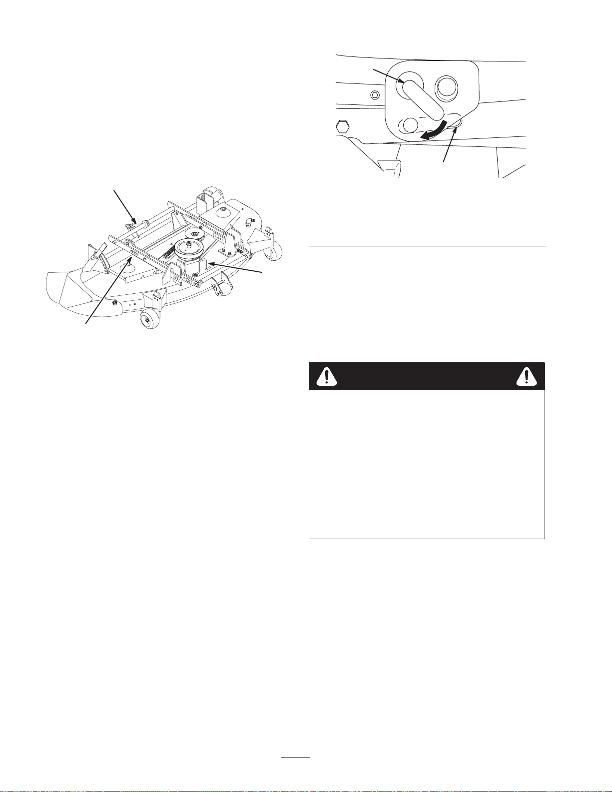
5. If an adjustment is required, turn the adjusting nut
(Fig. 17) on the back of the mower. To raise the front of
the mower, turn the adjustment nut clockwise. To lower
the front of the mower, turn the nut counterclockwise.
1
1. Disengage the PTO, set the parking brake, lower the
attachment lift, stop the engine, and remove the ignition
key.
2. Carefully rotate one of the blades so it is oriented front
to rear (Fig. 16).
m–3519
Figure 17
1. Front to rear adjustment rod
9
Page 10

Adjusting the Side-to-Side Blade Cut
This optional adjustment is available if necessary to
compensate for uneven side-to-side cut.
Equalize side-to-side cut by adjusting the two carriage bolts
(Fig. 18) on the mower. Check the height of the blade at
outside blade tips (Fig. 16).
1
m–3459
Figure 18
1. Side-to-side adjustment bolts
Adjusting the Blade Slope for Transport
Because the attachment lift is used when the PTO drive is
engaged, you must adjust the transport blade slope to
extend the PTO drive belt life. This adjustment also
provides adequate transport height.
3
4
5
1
6
2
m–3518
Figure 19
Right Side of Tractor Shown
1. Indicator
2. Adjustment cam
3. Lift arm
4. Pivot point
5. Lowers front of deck
6. Raises front of deck
2. If they are not, park the machine on a level surface, set
the parking brake, lower the attachment lift to take
pressure off the cams, stop the engine, and remove the
ignition key.
Important Failure to adjust for blade slope in transport
can result in drive belt failure and/or insufficient transport
height.
1. Check to see that both adjustment cams are oriented
with the indicator toward the pivot point at the rear of
the tractor (Fig. 19).
Caution
Movement of the attachment lift between the
mower mounting brackets and the attachment lift
arms can injure a person when aligning the deck
with the lift arms.
• Keep hands away from moving parts while
operating the attachment lift.
• Set the parking brake, lower the attachment lift,
stop the engine, and remove the ignition key
before making any adjustments.
3. Loosen the nuts on the cams, rotate the cams to the
proper position, then tighten the cam nuts.
4. Start the tractor and raise the attachment lift.
5. Stop the engine and remove the ignition key.
6. Check the slope of one of the blades (Fig. 16).
A. Measure the distance from the front tip of the blade
to the flat surface.
B. Carefully rotate the blade tip until it is in the rear
position and measure it there.
10
Page 11

When the blade tip is in the front position, it should
be approximately 1/4 in. (7 mm) lower than when it
is in the rear position.
7. To adjust the blade slope, start the tractor, lower the
attachment lift to take pressure off the cams, stop the
engine, and remove the ignition key.
8. Loosen the cam nuts and equally rotate the left and right
cams down to raise the front of the mower, or up to
lower it. Tighten the nuts.
9. Repeat steps 4 through 8 until the slope of the blade is
approximately 1/4 in. (7 mm) lower in the front than it
is in the rear.
Removing the Mower
Remove the mower on a level, concrete surface. Rougher
dirt or lawn surfaces make removing the mower more
difficult.
1. Set the parking brake, start the tractor, and raise the
attachment lift.
3
2
1
m–5511
Figure 20
1. Belt tension release arm
2. Belt tension adjustment
knob
3. Belt tension released
7. Remove the belt from around the PTO pulley (Fig. 21).
Additional belt slack can be obtained (if needed) by
turning the belt tension adjustment knob.
2. Get off the tractor. Place the mower height-of-cut lever
in the lowest cut position.
3. Lower the mower until its weight is completely on its
wheels, not on the tractor.
4. Stop the engine and remove the ignition key.
5. Remove the grill.
Caution
Components under the hood will be hot if the
tractor has been running. If you touch hot
components you may be burned.
Allow the tractor to cool before performing
maintenance or touching components under the
hood.
6. Release the belt tension release arm on the pulley box to
release the tension on the drive belt (Fig. 20).
1
m–3454
Figure 21
1. PTO pulley
8. Replace the grill.
9. Press the button of the mid Attach-A-Matic and twist
the lever clockwise to release the mower (Fig. 22).
11
Page 12

2
2
3
2
1
m–3457
Figure 22
1. Mid Attach-A-Matic
button
2. Mid Attach-A-Matic
lever
10.Pull the two spring loaded J-pins from the deck lift arms
and twist them slightly so that they stay disengaged
(Fig. 23).
1
m–3456
Figure 23
1. J-pin
11. If you wish to remove the pulley box, push the latch
release buttons on the front Attach-A-Matic (Fig. 24)
and raise the latch levers to open the latches holding the
pulley box. Remove the pulley box.
1
m–5511
Figure 24
1. Front Attach–A–Matic
button (one on each side)
2. Front Attach–A–Matic
latches
3. Pulley box
12.Start the tractor and raise the attachment lift to provide
ample clearance to slide out the mower.
13.Stop the engine and remove the ignition key.
14.Slide the mower out from the right side of the tractor.
Operation
Danger
Without the grass deflector, discharge cover, or
complete grass catcher assembly mounted in place,
you and others are exposed to blade contact and
thrown debris. Contact with the rotating mower
blades and thrown debris will cause injury or
death.
• Never remove the grass deflector from the
mower because the grass deflector routes
material down toward the turf. If the grass
deflector is ever damaged, replace it
immediately.
• Never put your hands or feet under the mower.
• Never try to clear the discharge area or mower
blades unless you move the PTO to Off and
rotate the ignition key to Off. Also remove the
key and pull the wires off of the spark plugs.
12
Page 13

Operating the Mower
2
The power take off (PTO) engages and disengages power to
the mower. The attachment lift lever raises and lowers the
mower. For detailed information on operating your tractor’s
controls, refer to the tractor Operator’s Manual.
Cutting Modes
3
Depending on what you install on your mower, you can use
it to side discharge, mulch, or bag grass clippings.
Side Discharge Mode
All mower models have a hinged discharge chute that
disperses clippings to the side and down toward the turf.
Bagging Mode
You can also purchase various grass baggers and catchers
from your Authorized Toro Dealer that you can install on
your mower and tractor. A grass bagger/catcher catches the
grass clippings, allowing you to remove them completely
from your lawn.
Adjusting the Front Wheels
The two front adjustable wheels must be adjusted in the
proper hole location each time you change the
height-of-cut.
1. After selecting a height of cut, make sure the front
adjustable wheels are approximately 3/8 in. (9.5 mm)
off the ground.
2. To adjust the wheel height, remove the hairpin cotter
and pin to change hole location (Fig. 25).
1
1233
Figure 25
1. Wheel
2. Pin
3. Hairpin Cotter
Check for Debris
Each time you use the mower, be sure to check for debris
build up on and inside the rear transaxle cover (Fig. 26).
Remove any build up.
1
m–3436
Figure 26
1. Rear transaxle cover
3. Select a hole position so the wheel is approximately 3/8
in. (9.5 mm) off the ground for the height-of-cut
position to be used (Fig. 25).
4. Insert the pin and secure it with a hairpin cotter.
5. Repeat this adjustment on the other wheel.
Tips for Mowing Grass
• For best mowing and maximum air circulation, operate
the engine at the fastest throttle position.
• When using the mower for the first time, cut grass
slightly longer than normal to ensure the cutting height
of the mower does not scalp any uneven ground.
• Cut only about 1/3 of the grass blade. Cutting more than
that is not recommended, unless grass is sparse or it is
late fall when grass grows more slowly.
• Alternate mowing direction to keep the grass standing
straight. This also helps disperse clippings which
enhances decomposition and fertilization.
• Avoid mowing in reverse.
13
Page 14

• To improve cut quality, use slower ground speed. For
best results on average lawns, operate the engine at full
throttle while controlling the ground speed with the
transmission. Operate the tractor at 2 to 3.5 MPH (3.2
to 5.6 kms/hr) while mowing grass. Excessive ground
speed may result in uneven cutting.
• Air is required to thoroughly cut grass clippings, so do
not set the height-of-cut so low as to totally surround
the mower by uncut grass.
• Always try to have one side of the mower free from
uncut grass, which allows air to be drawn into the
mower.
• To cut long or wet grass, raise the cutting height and cut
the grass. Then, cut the grass again using the lower,
normal setting.
• If you must stop while mowing, a clump of grass
clippings may drop onto your lawn. To avoid this, move
onto a previously mowed area with the blades engaged
and then raise the attachment to disperse the clippings
evenly.
• Use the washout port to clean clippings and dirt from
the underside of the mower after each use. If grass and
dirt build up inside the mower, cutting quality will
eventually become unsatisfactory.
• If the cutting width of the mower is wider than the
mower you previously used, raise the cutting height to
ensure uneven turf is not cut too short. Average lawns
are usually cut at a height between 2 and 3 inches (5 to
7.6 cm).
• Keep the blade sharp. A sharp blade cuts cleanly
without tearing or shredding the grass blades. Tearing
and shredding slows growth and increases the chance of
disease. Every 30 days, check the blades for sharpness
and file down any nicks.
Maintenance
Note: Determine the left and right sides of the machine from the normal operating position.
Recommended Maintenance Schedule
Maintenance Service
Interval
Each Use • Wash the underside of the mower.
5 hours
25 hours • Grease the mower spindles.
50 Hours • Check the belt tension.
Storage Service
Maintenance Procedure
• Inspect the blades.
• Check the belt tension (initial check only).
• Wash the underside of the mower.
• Inspect the blades.
• Grease the mower spindles.
• Check the belt tension.
• Check the belts for wear and cracks.
• Paint chipped surfaces.
Caution
If you leave the key in the ignition switch, someone could accidently start the engine and
seriously injure you or other bystanders.
Remove the key from the ignition and disconnect the wires from the spark plugs before you do
any maintenance. Set the wires aside so that it does not accidentally contact the spark plugs.
14
Page 15

Servicing the Blades
To ensure a superior quality of cut, keep the blades sharp.
For convenient sharpening and replacement, you may want
to have extra blades.
Note: A block of wood may be wedged between the
blade and the mower to lock the blade when you are
removing the nut.
3. Inspect all parts. If damage is noticed, install new parts.
Danger
A worn or damaged blade can break, and a piece
of the blade could be thrown into the operator’s or
bystander’s area, resulting in serious personal
injury or death.
• Inspect the blade periodically for wear or
damage.
• Replace a worn or damaged blade.
1. Remove the mower; refer to Removing the Mower,
page 11.
2. Carefully turn the mower over to expose the blades
Inspecting the Blades
1. Inspect the cutting edges (Fig. 27).
2. If the edges are not sharp or have nicks, remove the
blades and sharpen them.
3. Inspect the blades, especially the curved area (Fig. 27).
4. If you notice any damage, wear, or a slot forming in this
area (Fig. 27), immediately install a new blade.
5
4
3
2
1
m–3585
Figure 28
1. Nut
2. Flat washer—thin
3. Blade
4. Washer—thick
5. Spindle
Sharpening a Blade
1. Use a file to sharpen the cutting edge at both ends of the
blade (Fig. 29).
Maintain the original angle. The blade retains its
balance if the same amount of material is removed from
both cutting edges.
1
2
1
3
151
Figure 27
1. Cutting edge
2. Curved area
3. Wear/slot forming
Removing the Blades
Important There are two different sizes of blades. The
shorter blade goes into the center spindle. The two longer
blades go on the outside spindles (Fig. 31).
1. Hold the blade end using a rag or thickly padded glove.
2. Remove the nut, two washers, and blade (Fig. 28).
Figure 29
1. Sharpen at original
angle
2. Check the balance of the blade by putting it on a blade
balancer (Fig. 30).
If the blade stays in a horizontal position, the blade is
balanced and can be used.
2
1
Figure 30
1. Blade 2. Balancer
3. If the blade is not balanced, file some metal off the back
side of the blade.
4. Repeat steps 2 and 3 until the blade is balanced.
15
Page 16

Installing the Blades
Important There are two different sizes and shapes of
blades. The shorter blade goes into the center spindle. The
two longer blades go on the outside spindles (Fig. 32). See
figure 31 for the shape difference.
2
1
2. Clean the grease fittings (Fig. 33) with a rag.
m–5707
Figure 31
1. Outside blade
2. Center blade
Figure 32
1. Long blade, 16–11/32 in. 2. Short blade, 15–27/32 in.
1. Hold the blade end using a rag or thickly padded glove.
2. Install the thick washer, blade, thin flat washer, and the
nut (Fig. 28).
Important The sail (curved part of the blade) must be
pointing up toward the inside of the mower to ensure
proper cutting.
3. Angle on sail of blade
Front
21
3
1
m–3519
Figure 33
3. Scrape any paint off the end of the fittings.
4. Connect a grease gun to each fitting (Fig. 33).
5. Pump grease into the fittings.
6. Wipe up any excess grease.
Checking PTO Drive Belt
Tension
Check the PTO drive belt tension after 5 hours of operating
with a new belt, then every 50 hours or once a year,
whichever occurs first.
1. Check the tension indicators on the front of the pulley
box. If the tension indicators do not line up, release the
belt tension and turn the adjustment knob. Push the belt
tension release arm back toward the pulley box to
tension the belt (Fig. 34).
3. Tighten the nut to 80 to 100 ft.-lb. (109 to 136 N⋅m).
Greasing the Blade Spindles
Grease the mower after every 25 operating hours or once a
year, whichever occurs first. Grease more frequently when
operating conditions are extremely dusty or sandy.
Grease Type: General-purpose grease.
How to Grease
1. Disengage the PTO, set the parking brake, lower the
attachment lift, stop the engine, and remove the ignition
key.
16
Page 17

2
5
3
1
m–3458
Figure 34
1. Belt tension release arm
2. Belt tension indicators
3. Belt tension adjustment
knob
4. Seating position for
tension arm
5. Belt tension released
2. Repeat step 1 until the indicators move to the same
position.
2. Remove the pulley cover mounting screws and pulley
covers from the blade pulleys (Fig. 35).
1
2
3
2
4
5
4
m-3525
Figure 35
Top View
1. Pulley cover screw
2. Pulley cover
3. Belt guide
4. Mower belt
5. Spring
3. Swing the tension release arm into the pulley box by
moving it into the position shown in Figure 34.
Extending PTO Drive Belt Life
The PTO drive belt will provide a long service life if
properly installed and operated. Check the following to
help extend belt life.
• Maintain correct belt tension.
• Maintain correct mower level.
• Maintain correct blade slope in transport.
• Adjust the position of the mower belt guide.
• Replace damaged pulleys.
• Always operate engine-powered attachments at full
throttle.
• Avoid engaging the PTO when the mower is in tall
uncut grass or weeds.
• Cut tall grass and weeds with the mower in its highest
position, making a second pass cutting at desired height.
• Regularly clean the mower of any buildup of grass
clippings.
• Use low range or reduce ground speed when mowing in
heavy conditions or when mulching or bagging.
3. Release the spring (Fig. 35).
4. Remove the belt from the pulleys (Fig. 35).
Installing the Blade Drive Belt
1. Install the new belt around the blade pulleys and the
idler pulleys.
2. Attach the spring (Fig. 35).
3. Install the left and right pulley covers with the
mounting screws (Fig. 35).
4. Install the mower; refer to Installing the Mower,
page 5.
Washing the Mower
After each use, wash the underside of the mower to prevent
grass build-up and improve performance.
1. Park the tractor on a hard level surface.
2. Apply the parking brake, start the tractor, and raise the
attachment lift.
3. Get off the tractor. Place the mower height-of-cut lever
in the lowest cut position.
4. Lower the attachment lift, stop the engine, and remove
the ignition key.
Replacing the Blade Drive Belt
Removing the Blade Drive Belt
1. Remove the mower; refer to Removing the Mower,
page 11.
5. Attach a hose coupling to the end of the washout fitting
and turn water on high (Fig. 36).
Note: Spread petroleum jelly on the washout fitting o-ring
to help the coupling slide on easier and protect the o-ring.
17
Page 18

1
3
2
9. Turn the water off and remove the hose coupling from
the washout fitting.
Note: If the mower is not clean after one washing, soak it
and let it stand for 30 minutes. Then repeat the process.
10.Run the mower again for one to three minutes to
remove excess water.
Warning
m–3586
Figure 36
1. Washout fitting
2. Coupling
6. Sit on the seat and start the engine.
7. Engage the PTO and let the mower run for one to three
minutes.
8. Disengage the PTO, stop the engine, and remove the
ignition key. Wait for all moving parts to stop.
3. Hose
Storage
1. Clean dirt and chaff from the top of the mower.
2. Scrape heavy buildup of grass and dirt from the
underside of the mower.
3. Use the wash out port to wash the underside of the
mower; refer to Washing the Mower, page 17.
4. Wash the top side of the mower with a garden hose.
A broken or missing washout fitting could expose
you and others to thrown objects or blade contact.
Contact with the blade or thrown debris will cause
injury or death.
• Replace a broken or missing washout fitting
immediately, before using the mower again.
• Plug any hole(s) in the mower with bolts and
locknuts.
• Never put your hands or feet under the mower
or through openings in the mower.
5. Check the condition of the blades.
6. Check the condition of the blade drive belt.
7. Check and tighten all bolts, nuts, and screws. Repair or
replace any part that is damaged.
8. Paint all scratched or bare metal surfaces. Paint is
available from you Authorized Service Dealer.
9. Store the mower in a clean, dry garage or storage area.
Cover the mower to protect it and keep it clean.
18
Page 19

Troubleshooting
gg
Problem Possible Causes Corrective Action
Abnormal vibration.
Blades do not rotate.
Uneven cutting height.
1. A blade is bent or unbalanced. 1. Install new blades.
2. A blade mounting bolt is loose. 2. Tighten the blade mounting
bolts.
3. The engine mounting bolts are
loose.
4. A loose engine pulley, idler
pulley, or blade pulley.
5. The engine pulley is damaged. 5. Contact your Authorized
1. The blade drive belt is worn,
loose, or broken.
2. The blade drive belt is off the
pulley.
3. The PTO belt is worn, loose, or
broken.
1. The tire pressure is incorrect. 1. Set tire pressure.
2. The mower is not level. 2. Level the mower from
3. The underside of the mower is
dirty.
3. Tighten the engine mounting
bolts.
4. Tighten the appropriate pulley .
Service Dealer.
1. Install a new blade drive belt.
2. Install the blade drive belt and
check idler pulley and belt
guides for correct position.
3. Install a new PTO belt.
side-to-side and front-to-rear.
3. Clean the underside of the
mower.
Insufficient transport height. 1. The lift arm cams are
improperly adjusted.
1. Adjust lift arm cams.
19
Page 20

Problem Corrective ActionPossible Causes
PTO drive belt comes off of
pulleys,slips or fails.
1. The belt tension is incorrect. 1. Adjust the belt tension.
2. The mower level is incorrect. 2. Adjust the mower level.
3. The blade slope in transport is
incorrect.
4. The mower belt guide is loose
or incorrectly adjusted.
5. The belt is worn or damaged. 5. Install a new belt.
6. The Pulley is damaged. 6. Contact your Authorized
7. The engine is not at full throttle. 7. Always operate
8. The PTO is being engaged
when the mower is in tall uncut
grass or weeds.
9. The mower is overloaded
because mulching or bagging
requires more power.
10.The mower is overloaded
because too much grass is
being cut at a time.
3. Adjust the blade slope in
transport.
4. Adjust and tighten the belt
guide.
Service Dealer.
engine-powered attachments at
full throttle.
8. Engage the PTO only in shorter
or previously cut grass.
9. Reduce the ground speed
when mulching or bagging.
10.Cut tall grass and weeds with
the mower in its highest
position, making a second pass
cutting at height desired.
11.The mower is overloaded
because deck is clogged with
grass clippings.
12.The mower is overloaded
because tractor is mowing too
fast for conditions.
11.Clean the mower.
12.Reduce ground speed.
20
 Loading...