

Page 1

FORM NO. 3322–624
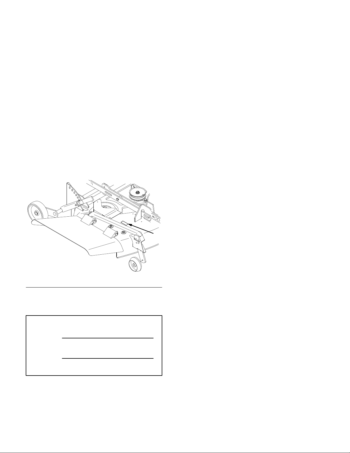
Wheel
Horse
44” Side Discharge
for
Mower
5xi Lawn and Garden T
Model No. 78444 – 8900001 & Up
ractors
Operator’s Manual
IMPORTANT: Read this manual, and your tractor manual, carefully. They
contain information about your safety and the safety of others. Also
become familiar with the controls and their proper use before you operate
the product.
International English (GB)
Page 2
Introduction
We want you to be completely satisfied with your
new product, so feel free to contact your local
Authorized Service Dealer for help with service,
genuine replacement parts, or other information you
may require.
Whenever you contact your Authorized Service
Dealer or the factory, always know the model and
serial numbers of your product. These numbers will
help the Service Dealer or Service Representative
provide exact information about your specific
product. You will find the model and serial number
plate located in a unique place on the product as
shown below
.
The warning system in this manual identifies
potential hazards and has special safety messages that
help you and others avoid personal injury, even death.
DANGER, WARNING and CAUTION are signal
words used to identify the level of hazard. However,
regardless of the hazard, be extremely careful.
DANGER signals an extreme hazard that will cause
serious injury or death if the recommended
precautions are not followed.
WARNING signals a hazard that may cause serious
injury or death if the recommended precautions are
not followed.
CAUTION signals a hazard that may cause minor or
moderate injury if the recommended precautions are
not followed.
Two other words are also used to highlight
information. “Important” calls attention to special
mechanical information and “Note” emphasizes
1
general information worthy of special attention.
m–3464
1. Model
For your convenience, write the product model and
serial numbers in the space below.
Model No:
Serial No.
and Serial Number Plate
The left and right side of the machine is determined
by sitting on the seat in the normal operator’s
position.
Printed in USA
The TORO Co. – 1998
Page 3

Contents
Page
Safety and Instruction Decals 2.
Installation 3
Loose Parts 3
Mower Preparation 3
Installing the Mower 4
Attach the PTO Drive Belt 6
Adjusting the Mower 8
Removing the Mower 11
Operation 14
Side Discharge 14
Operating the Power Take Off (PTO) 14
Attachment Lift Lever 15
Adjusting Anti-Scalp Rollers 16
Adjusting the Two Front Wheels 16
Check for Debris 17
Tips for Mowing Grass 17
. . . . . . . . . . . . . . . . . . . . . . . . . . . . .
. . . . . . . . . . . . . . . . . . . . . . . . .
. . . . . . . . . . . . . . . . . . .
. . . . . . . . . . . . . . . . . . . . . . . . . . . . . .
. . . . . . . . . . . . . . . . . . . . . .
. . . . . . . . . . . . . . . . . . . .
. . . . . . . . . . . . .
. . . . . . . . . . . . . . . . .
. . . . . . . . . . . . .
. . . . . . . . . . . . . . . . .
. . . . . . . . . . . . . . . . .
. . . .
. . . . . . . . . . . . . . . .
. . . . . . . . . . .
. . . . . . . .
. . . . . . . . . . . . . . .
Page
Maintenance 19
Service Interval Chart 19
Cutting Blade20. . . . . . . . . . . . . . . . . . . . . . .
Greasing and Lubrication 21
Checking PTO Drive Belt Tension 22
Extending PTO Drive Belt Life 22
Blade Drive Belt 23
Washing the Underside of the Mower 23
Storage 24
Troubleshooting 25
. . . . . . . . . . . . . . . . . . . . . . . . . . . .
. . . . . . . . . . . . . . . .
. . . . . . . . . . . . . .
. . . . . .
. . . . . . . . .
. . . . . . . . . . . . . . . . . . . . .
. . . .
. . . . . . . . . . . . . . . . . . . . . . . . . . . .
. . . . . . . . . . . . . . . . . . . . . . . . .
1
Page 4
Safety
Safety
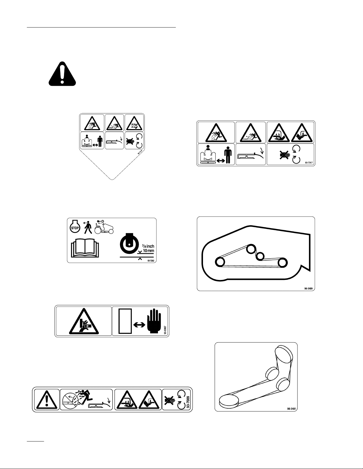
and Instruction Decals
Safety decals and instructions are easily visible to the operator and are located near
any area of potential danger. Replace any decal that is damaged or lost.
ON GRASS DEFLECT
(Part No. 93–7316)
NEXT T
O GAGE WHEELS
(Part No. 93–7282)
OR
(1) ON GRASS DEFLECT
(1) ON DECK LEFT SIDE
(Part No. 93–7317)
ON MOWER REAR T
(Part No. 98–3489)
OP
OR
(2) ON LEVELER BAR
(Part No. 93–9367)
ON MOWER RIGHT SIDE
(Part No. 98–3481)
UNDER GRASS DEFLECT
(Part No. 93–7009)
2
OR
Page 5
Installation
Loose
Parts
Note: Use the chart below to identify parts used for assembly.
DESCRIPTION QTY. USE
Discharge chute
Spring
Bolt 3/8–24 x 3–1/2”
Lock nut 3/8”
PT
O drive belt
Pulley box
Operator’
Mower
s Manual
Preparation
1
2
2
2
1
1
1
Install discharge chute
Install PT
Install pulley box
Read before operating
O drive belt
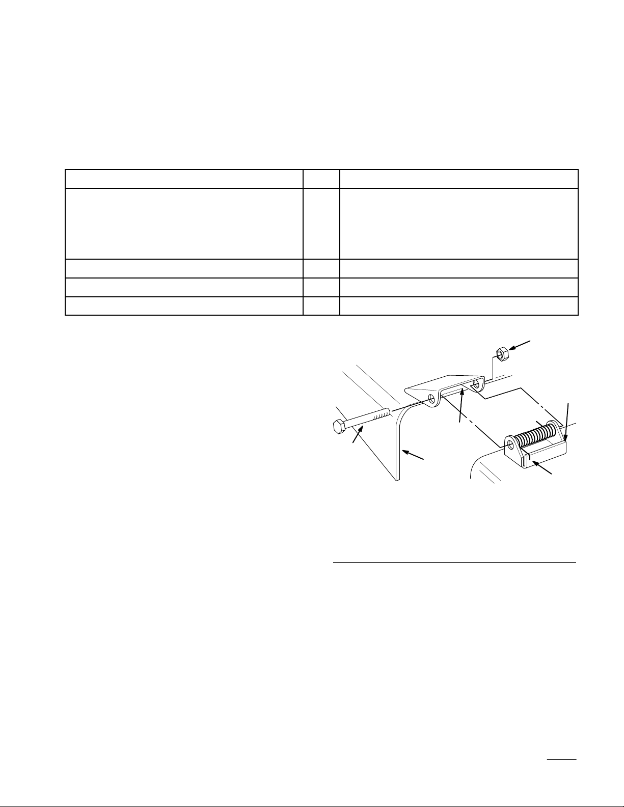
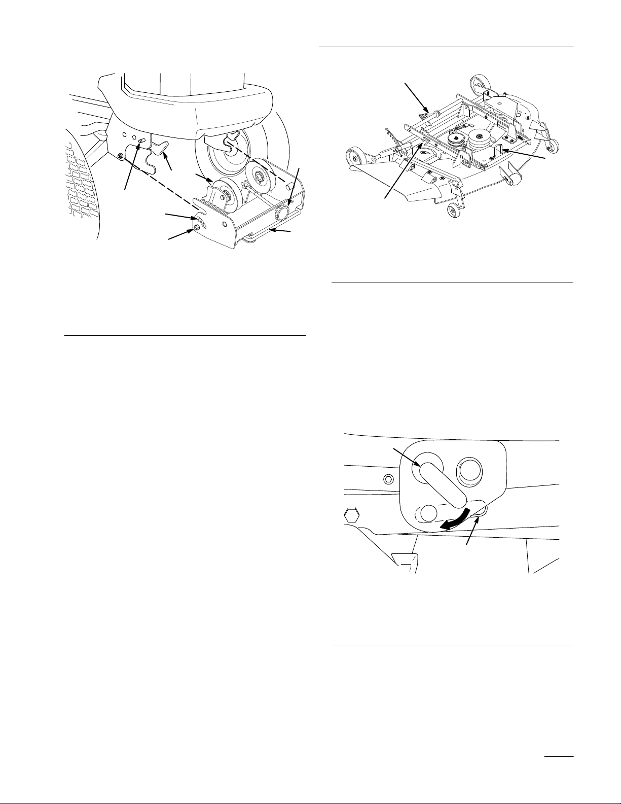
Install the Discharge Chute
1. Place the springs into the brackets on the mower
with the hooked ends over the raised back of the
bracket (Fig. 1).
6
1
3
2. Align the discharge chute with the holes in the
brackets and the spring straight ends in the space
under the hinge and above the chute (Fig. 1).
3. Secure the chute to the bracket with bolts
through the discharge chute, springs and
brackets. Secure with lock nuts (Fig. 1).
4. Lift the discharge chute and check that it is
spring loaded and pivots freely to the full down
position.
IMPORTANT: Discharge chute must be
spring loaded in the down position. Lift the
chute up to test that it snaps to the full down
position.
5
1. Bracket
2. Spring
3.
Space for spring
hook end
4
Figure 1
4.
Discharge chute
5. Bolt
6.
Lock nut
2
m–3484
3
Page 6
Installation
POTENTIAL
HAZARD
• Without the discharge chute or the
complete grass catcher assembly mounted
in place, you and others are exposed to
blade contact and thrown debris.
WHAT CAN HAPPEN
• Contact with rotating mower blade(s) and
thrown debris will cause injury or death.
HOW TO AV
•
NEVER r
OID THE HAZARD
emove the discharge chute from
the mower because the discharge chute
routes material down toward the turf. If
the discharge chute is ever damaged,
replace it immediately. Never put your
hands or feet under the mower.
• Never try to clear the discharge area or
mower blades unless you move the power
take off (PTO) to “OFF” and turn the
ignition key to “STOP.” Also remove the
ignition key and pull the wire(s) off the
spark plug(s).
Installing
the Mower
Initial Preparation
The mower is most easily installed when done on a
level concrete surface. Rougher dirt or lawn surfaces
make installation more difficult.
1. Position the tractor and mower side by side, with
the mower on the right–hand side of the tractor.
2. Set the parking brake, raise the attachment lift,
and turn the ignition key to “STOP” to stop the
engine. Remove the ignition key.
3. If you have previously had a snowthrower, blade
or tiller attached to the attachment lift, remove
the two clevis pins on each side of the
attachment lift (Fig. 3).
Mower Belt Routing
1. Route the mower belt as shown in Fig. 2. Be
sure to install the belt on the lower mower deck
pulley.
2
2.
Mower deck pulley
1. Mower
1
belt
Figure 2
T
op V
iew
m–3472
1
m–3433
Figure 3
1. Clevis
pin
2.
Hairpin cotter
4. Attach the pulley box if it is not already on the
tractor. Make sure the latches on the tractor’s
front Attach-A-Matic
slide the pulley box into the Attach-A-Matic
TM
are open (Fig. 4). Then
TM
latches and seat it. Close the latches.
2
4
Page 7
Installation
3
3
1
7
6
22
Figure 4
TM
1. Attach-A-Matic
2. Pulley
3.
4.
box
Idler pulley
Belt tension release arm
latches
5.
Belt tension adjustment
knob
6.
Belt tension indicators
(one on each side)
7. Attach-A-Matic
TM
button
Attach the Mower
1. Make sure the mower wheels are set for low
height of cut.
2. Make sure the attachment lift is in the full up
position.
4
m–3463
5
2
1
m–3460
Figure 5
1. Slots
2.
in the side mounting
brackets (2)
Belt guide
3.
Front–to–rear adjustment
rod
5. Start the tractor.
6. Lower the attachment lift arm fully and adjust
the deck’s position until you can pull out on the
J–pin of the lift arm and slide it into the slot in
the mounting bracket of the mower (Fig. 6).
7. On the driver’s left–hand side, pull out the
attachment lift J–pin and slide it into the slot on
the other mower mounting bracket.
1
3. From the driver’s right–hand side of the tractor,
slide the mower under the tractor.
4. After sliding the mower under the tractor,
position it so that the slots in the side of each of
the mower’s mounting brackets (Fig. 5) are
aligned directly below the tractor’
s attachment
lift arm.
2
Figure 6
Left Side of Tractor Shown
1. J–pin 2. Mower
mounting bracket.
m–3456
slot in side
5
Page 8
Installation
8. After the two J–pins are seated through the
mower’s mounting brackets, using the
attachment lift and your hand on the right front
adjustable mower wheel bracket (Fig. 7),
position the mower so its attachment bar fits into
the mid Attach-A-Matic
POTENTIAL
HAZARD
TM
mount.
• The “scissor” formed by the mower
mounting brackets and the attachment lift
arm is dangerous.
WHAT CAN HAPPEN
• Hands and fingers can get caught between
the mower parts and the tractor and be
injured.
HOW TO AV
OID THE HAZARD
• Keep hands away from moving parts while
operating the attachment lift.
• Always position the mower with your hand
on the right front mower wheel bracket.
• Never try to position the mower with your
hands on the mower mounting brackets or
below the mower housing.
10. Set the parking brake, lower the attachment lift,
and turn the ignition key to “STOP” to stop the
engine. Then remove the ignition key.
3
1. Attach-A-Matic
2. Attach-A-Matic
Attach
the PT
TM
TM
1
Figure 8
button
lever
3. Lock
O Drive Belt
2
m–3611
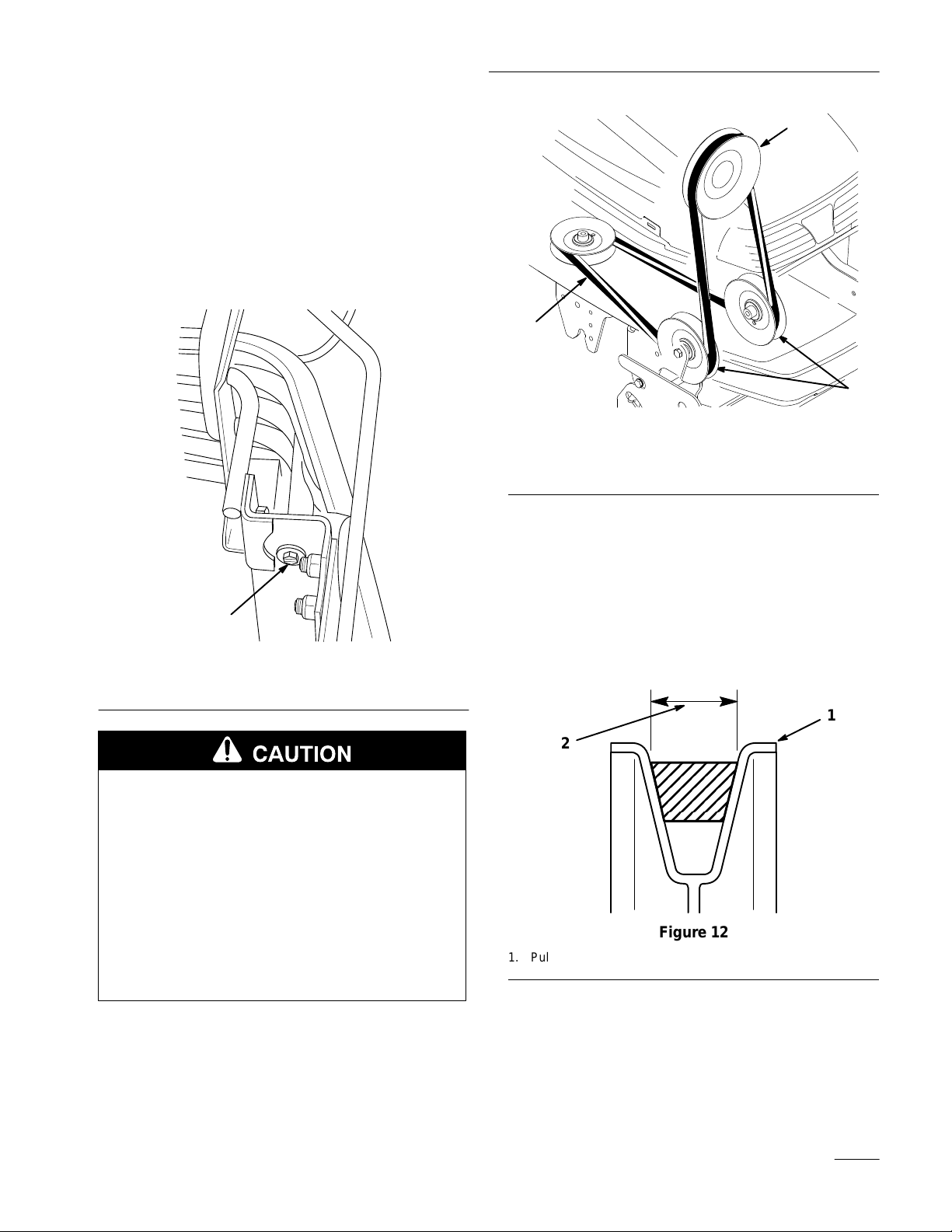
1. Hang the belt over the mower, then thread it
forward through the belt guide (Fig. 9) on the
mower.
1
Figure 7
1. Place
hand here
9. Turn the lever of the Attach-A-Matic
counterclockwise to lock the mower to the
tractor (Fig. 8).
6
TM
m–3500
2
m–3457
1
Figure 9
1. Belt 2. Belt
guide
2. Extend the belt through the center of the pulley
box, between the two pulleys.
Page 9
Installation
3. Release the belt tension release arm on the
pulley box housing and swing it out toward you
(Fig. 13).
4. Remove the tractor’s front grill by raising the
hood and unscrewing the two screws and
washers securing it in place (Fig. 10). Close the
hood and remove the grill by pulling it out
toward you.
2
3
m–4231
1. Pulley
2. PT
O pulley
Figure 1
box pulley
1
3. PT
O drive belt
6. Loop the other end of the belt over the drive
pulley of the mower. Additional belt slack can
be obtained (if needed) by turning the belt
tension adjustment knob (Fig. 13).
1
1
Figure 10
1. Grill
screw (1 of 2)
POTENTIAL
HAZARD
• Components under the hood will be hot if
the tractor has been running.
WHAT CAN HAPPEN
• Touching hot components can cause burns.
HOW TO AV
OID THE HAZARD
• Allow the tractor to cool before performing
maintenance or touching components
under the hood.
5. Position the belt into the grooves of the PTO
pulley (Fig. 11), making sure it is also under the
pulleys in the pulley box.
m–3558
7. Make certain that the wide side of the PTO drive
belt is toward the outside diameter of all (four)
pulleys (Fig. 12).
1
2
m–4230
Figure 12
1. Pulley
outside diameter
2.
Wide side of belt
8. Now adjust the belt tension.
A. Push the belt tension release arm back
toward the pulley box to tension the belt.
7
Page 10

Installation
B. Check the tension indicators on each side of
the pulley box.
C. If the tension indicators are not in the same
position on both the left and right sides,
release the belt tension, turn the adjustment
knob and repeat steps A and B until the
indicators move to the same position (Fig.
13).
D. Once the indicators are in the same position
on both sides, swing the tension release arm
into the pulley box and seat it by moving it
into the position shown in Figure 13.
2
2
3
1
4
m–3465
Figure 14
1. Belt
guide
2. Belt
Belt touches here
3.
4.
Belt guide bolt
11. Tighten the belt guide bolt.
12. Replace the front grill of the tractor, securing it
with two previously removed screws and
washers (Fig. 10).
4
3
m–3458
1
Figure 13
1. Belt
tension release arm
2.
Belt tension indicator (2)
3.
Belt tension adjustment
knob
Seating position for
4.
tension arm
5.
Belt tension released
9. Loosen the belt guide bolt (Fig. 14).
10. Adjust the belt guide so that it just touches the
belt on the inside arm of the guide, toward the
center of the deck (Fig. 14).
Adjusting
the Mower
5
Adjusting the Height of Cut
The rear gauge wheels are adjusted in different hole
locations for 1—4” (3–10 cm) heights of cut.
1. Start the tractor, apply the parking brake, and
raise the deck. Get off the tractor. Pull the
height–of–cut lever out to disengage it from the
quadrant. Adjust the height of cut to the desired
level. Release the lever inward to lock into the
quadrant (Fig. 15).
8
Page 11

Installation
1
3
4
2
m–3474
Figure 15
1. Height-of-cut
2. Quadrant
lever
3. High
4. Low
Checking Mower Level
For optimum efficiency, the level of the mower
should be checked at the time of initial installation
and periodically as a check, to ensure that the blades
are 1/8” (3 mm) lower in the front than in the rear.
The mower must be checked and adjusted on a flat
level surface, preferably concrete. Before checking
the mower level, set the air pressure in the front and
rear tires as specified in the tractor operator’s manual.
Place the mower height–of–cut lever to the middle
cut position. Make sure the two adjustable front
wheels are off the ground.
Front
m–3522
2
3
1
4
4
Figure 16
1. Blade
2. Measure
3. Rotate
oriented
front blade tip
front tip to rear and
measure
front to rear
Measure here (side to
4.
side)
4. Front–to–rear adjustment is made by turning the
adjusting nut (Fig. 17) on the back of the mower.
To raise the front of the mower, turn the
adjustment nut clockwise. To lower the front of
the mower, turn the nut counterclockwise.
1
Adjusting Front–to–Rear Blade Cut
1. Disengage the power take off (PTO), set the
parking brake, lower the attachment lift, and turn
the ignition key to “STOP” to stop the engine.
Remove the ignition key.
2. Carefully rotate one of the blades so it is facing
front and rear (Fig. 16).
3. Measure the distance from the front tip of the
blade (Fig. 16) to the flat surface. Then
carefully rotate the blade tip until it is in the rear
position. When the blade tip is in the front
position, it should be 1/8” (3 mm) lower than
when it is in the rear position.
m–3460
Figure 17
1. Front–to–rear
rod
adjustment
Adjusting Side–to–Side Blade Cut
This optional adjustment is available if necessary to
compensate for uneven side–to–side cut.
9
Page 12

Installation
Equalize side–to–side cut by adjusting the two
carriage bolts (Fig. 18) on the mower. Check height
of blade at outside blade tips as shown (Fig. 16).
3
4
1
m–3459
Figure 18
1. Side–to–side
bolts
adjustment
Adjusting the Blade Slope for Transport
Because the attachment lift is used when the PTO
drive is engaged, blade slope in transport must be
adjusted to extend PTO drive belt life. This
adjustment also provides for adequate transport
height. Three steps accomplish this: 1) Making sure
the lift arm cams are in the same position, 2)
Measuring blade slope in its front and rear positions
and 3) Making adjustments if the blade slope is not
within specification.
5
1
6
2
Figure 19
1. Indicator
2. Adjustment
3.
Lift arm
Right Side of T
cam
ractor Shown
4.
Pivot point
5.
Lowers front of deck
6.
Raises front of deck
2. If they are not, park the machine on a level
surface, set the parking brake, lower the
attachment lift to take pressure off the cams, and
turn the ignition key to “STOP” to stop the
engine. Remove the ignition key.
m–3518
IMPORTANT: Failure to adjust for blade
slope in transport can result in drive belt
failure and/or insufficient transport height.
1. Check to see that both adjustment cams are
oriented with the indicator toward the pivot point
at the rear of the tractor (Fig. 19).
10
Page 13

POTENTIAL HAZARD
• The “scissor” formed by the mower
mounting brackets and the attachment lift
arm is dangerous.
Installation
8. Repeat steps 4–7 until the slope of the blade is
approximately 1/4” (7 mm) lower in the front
than it is in the rear.
Removing
the Mower
WHAT CAN HAPPEN
• Hands and fingers can get caught between
the mower parts and the tractor and be
injured.
HOW TO AV
OID THE HAZARD
• Keep hands away from moving parts while
operating the attachment lift.
• Set the parking brake, lower the
attachment lift, turn the ignition key to
“STOP” to stop the engine, and remove the
ignition key before making any
adjustments.
3. Loosen the nuts on the cams, rotate the cams to
the proper position, then tighten the cam nuts.
4. Start the tractor, raise the attachment lift and turn
the ignition key to “STOP” to stop the engine.
Remove the ignition key.
5. Check the slope of one of the blades (Fig. 16).
The mower is most easily removed from the tractor
when done on a level concrete surface. Rougher dirt
or lawn surfaces make removing the mower more
difficult.
1. Apply the parking brake, start the tractor, and
raise the attachment lift.
2. Get off the tractor. Place the mower
height–of–cut lever in the lowest cut position.
3. Lower the deck until its weight is completely on
its wheels, not on the tractor.
4. Turn the ignition key to “STOP” to stop the
engine. Remove the ignition key.
5. Remove the tractor’s front grill by raising the
hood and unscrewing the two screws and
washers securing it in place (Fig. 10). Close the
hood and remove the grill by pulling it out
toward you.
A. Measure the distance from the front tip of
the blade to the flat surface.
B. Carefully rotate the blade tip until it is in
the rear position.
C. When the blade tip is in the front position,
it should be approximately 1/4” (7 mm)
lower than when it is in the rear position.
6. If it is not, start the tractor, lower the attachment
lift to take pressure off the cams, and turn the
ignition key to “STOP” to stop the engine.
Remove the ignition key.
7. Loosen the cam nuts and equally rotate the
left–hand and right–hand cams down to raise the
front of the deck, or up to lower the front of the
deck. Tighten the nuts.
POTENTIAL HAZARD
• Components under the hood will be hot if
the tractor has been running.
WHAT CAN HAPPEN
• Touching hot components can cause burns.
HOW TO AV
OID THE HAZARD
• Allow the tractor to cool before performing
maintenance or touching components
under the hood.
6. Release the belt tension release arm on the
pulley box to release the tension on the drive belt
(Fig. 20).
11
Page 14

Installation
2
m–3458
1
Figure 20
1. Belt
tension release arm
2.
Belt tension adjustment
knob
3.
Belt tension released
7. Remove the belt from around the PTO pulley
(Fig. 21). Additional belt slack can be obtained
(if needed) by turning the belt tension
adjustment knob.
9. Press the button of the mid Attach-A-Matic
TM
and twist the lever clockwise to release the
mower (Fig. 22).
3
2
1
m–3457
Figure 22
1. Mid
button
Attach-A-Matic
TM
2.
Mid Attach-A-Matic
lever
TM
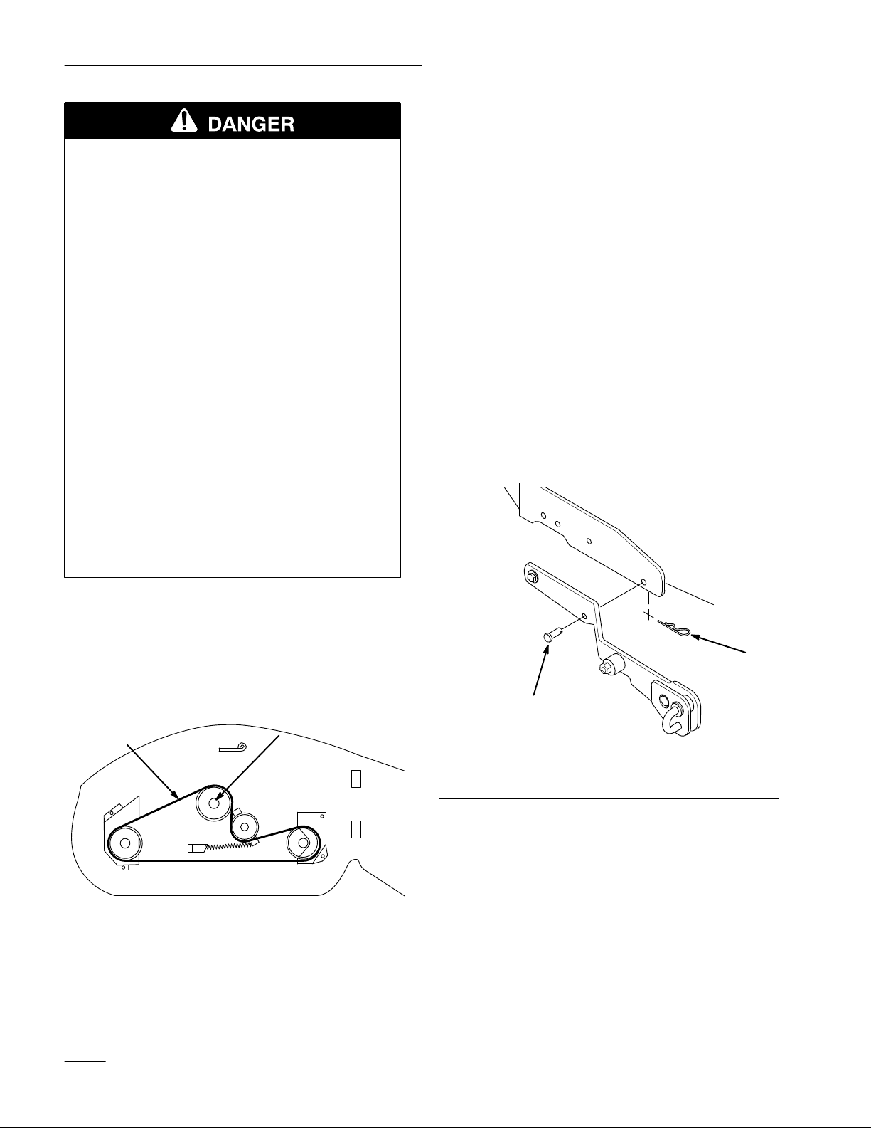
10. Pull the two spring–loaded J–pins from the deck
lift arms and twist them slightly so that they stay
disengaged (Fig. 23).
1
m–3454
Figure 21
1. PTO
pulley
8. Replace the front grill of the tractor, securing it
with two previously removed screws and
washers (Fig. 10).
12
1
m–3456
Figure 23
1. J–pin
Page 15

11. If you wish to remove the pulley box, push the
latch release buttons on the front
Attach-A-Matic
TM
(Fig. 24) and raise the latch
levers to open the latches holding the pulley box.
Remove the pulley box.
Installation
2
2
1
3
m–3458
Figure 24
1. Front
2.
Attach-A-Matic
button (one on each side)
Front Attach-A-Matic
latches
TM
TM
Pulley box
3.
12. Start the tractor and raise the attachment lift to
provide ample clearance to slide out the mower.
Then turn the ignition key to “STOP” to stop the
engine. Remove the ignition key.
13. Slide the mower out from the driver’s right–hand
side of the tractor.
13
Page 16

Operation
Side
The mower has a hinged grass deflector that disperses
clippings to the side and down toward the turf.
Discharge
POTENTIAL HAZARD
• Without the discharge chute or complete
grass catcher assembly mounted in place,
you and others are exposed to blade contact
and thrown debris.
WHAT CAN HAPPEN
• Contact with rotating mower blade(s) and
thrown debris will cause injury or death.
HOW TO AV
•
NEVER r
the mower because the discharge chute
routes material down toward the turf. If
the discharge chute is ever damaged,
replace it immediately.
OID THE HAZARD
emove the discharge chute from
• Never put your hands or feet under the
mower.
• Never try to clear the discharge area or
mower blades unless you move the power
take off (PTO) to “OFF” and rotate the
ignition key to “STOP.” Also remove the
ignition key and pull the wire(s) off the
spark plug(s).
While the ignition key is in RUN or LIGHTS
position and the power take off (PTO) is engaged, the
PTO indicator light will be on. When this light is ON,
it is a reminder: the implement is being powered and
the starter will not crank while the PTO is engaged.
Always turn off the PTO before getting off the seat.
Engaging the Power Take Off (PTO)
1. Depress the brake pedal to stop the machine.
2. Move the throttle lever to FAST.
IMPORTANT: For best performance, always
use full throttle when the power take off
(PTO) switch is ON.
3. Pull the power take off (PTO) switch to ON
(Fig. 25).
2
m–3264
1. Push
1
(of
f-disengaged) 2.
Figure 25
Pull (on-engaged)
Operating
the Power T
(PTO)
The power take off (PT
power to the electric clutch.
14
O) engages and disengages
ake Off
Disengaging the Power Take Off (PTO)
1. Push the power take off (PTO) switch to OFF.
Page 17

Operation
Attachment
Lift Lever
The attachment lift lever (Fig. 26 & 27) is used to
raise and lower various attachments.
Raising Attachments
1. Start the tractor.
2. Pull the attachment lift lever upward until the
latch locks. In this position, the lift will hold the
attachment in the up, or raised position.
POTENTIAL HAZARD
• When the engine is off, attachments in the
raised position can gradually lower.
WHAT CAN HAPPEN
• Someone nearby may be pinned or injured
by the attachment as it lowers.
1. Attachment
1
m–3258
Figure 26
lift lever
1
2
HOW TO AV
OID THE HAZARD
• Always lower the attachment each time you
shut off the tractor.
Lowering Attachments
1. Start the tractor.
2. Push the attachment lift lever downward to
lower the attachment.
1. Raise
attachment
Figure
27
2.
Lower attachment
m–3315
15
Page 18

Operation
Adjusting
Anti-Scalp Rollers
The anti-scalp rollers guide the mower over uneven
turf without scalping the lawn. For most cutting
conditions they should be located in the lower hole.
When cutting in 1-1/2” height-of-cut or lower move
the anti-scalp rollers to the upper hole position.
1. Raise the attachment lift lever; refer to Raising
Attachments.
2. Remove the cotter pin, bolt and shaft to change
hole location (Fig. 28).
3. Select the hole position for the height-of-cut to
be used and insert the rod (Fig. 28).
4. Secure the rod with the bolt and cotter pin.
3
Adjusting
the T
wo Front
Wheels
The two front adjustable wheels must be adjusted in
the proper hole location for each time you change
deck height-of-cut position.
1. After selecting height of cut, make sure the front
adjustable wheels are approximately 3/8” (9.5
mm) off the ground.
2. To adjust wheel height off the ground, remove
the hairpin cotter and pin to change hole location
(Fig. 29).
3. Select a hole position so the wheel is
approximately 3/8” (9.5 mm) off the ground for
the height-of-cut position to be used (Fig. 29).
4. Insert the pin and secure it with a hairpin cotter.
5. Repeat this adjustment on the other wheel.
1. Roller
2. Cotter
3. Bolt
4
pin
5
6
2
1
m–3609
Figure 28
4. Rod
5.
Upper hole
6.
Lower hole
3
1. Wheel
2. Pin
1
Figure 29
3. Hair
pin Cotter
2
1233
16
Page 19

Operation
Check
Each time you use the mower, be sure to check for
debris build up on and inside the rear transaxle cover
(Fig. 30). Remove any build up.
1. Rear
Tips
for Debris
1
m–3436
Figure 30
transaxle cover
for Mowing Grass
Fast Throttle Setting
Cut 1/3 of the Grass Blade
It is best to cut only about 1/3 of the grass blade.
Cutting more than that is not recommended, unless
grass is sparse or it is late fall when grass grows more
slowly.
Mowing Direction
Alternate mowing direction to keep the grass standing
straight. This also helps disperse clippings which
enhances decomposition and fertilization. Avoid
mowing in reverse.
Mow at Correct Intervals
Normally, mow every 4 days. But remember, grass
grows at different rates at different times. So to
maintain the same cutting height, which is a good
practice, mow more often in early spring. As the
grass growth rate slows in mid summer, mow less
frequently. If you cannot mow for an extended period,
first mow at a high cutting height; then mow again 2
days later at a lower height setting.
For best mowing and maximum air circulation,
operate the engine at “FAST.” Air is required to
thoroughly cut grass clippings, so do not set the
height-of-cut so low as to totally surround the mower
by uncut grass. Always try to have one side of the
mower free from uncut grass, which allows air to be
drawn into the mower.
Using the Mower for the First Time
Cut grass slightly longer than normal to ensure the
cutting height of the mower does not scalp any
uneven ground. However, the cutting height used in
the past is generally the best one to use. When cutting
grass longer than six inches tall, you may want to cut
the lawn twice to ensure an acceptable quality-of-cut.
Ground Speed
To improve cut quality, use slower ground speed. For
best operation on average lawns, operate engine at
full throttle while controlling ground speed with
transmission. Tractor should be operated at 2 to 3.5
MPH (3.2 to 5.6 kms/hr) while mowing grass.
Uneven cutting is often a result of excessive ground
speed. To correct, use low range with the high–low
lever, or reduce ground speed in high range.
Avoid Cutting Too Low
If the cutting width of the mower is wider than the
mower you previously used, raise the cutting height
to ensure uneven turf is not cut too short. Average
lawns are usually cut at a height between 2 and 3
inches (5–7.6 cm).
17
Page 20

Operation
Long Grass
If the grass is ever allowed to grow slightly longer
than normal, or if it contains a high degree of
moisture, raise the cutting height higher than usual
and cut the grass at this setting. Then cut the grass
again using the lower, normal setting.
When Stopping
If the machine’s forward motion must be stopped
while mowing, a clump of grass clippings may drop
onto your lawn. To avoid this:
1. With the blade(s) “ENGAGED,” move onto a
previously cut area.
2. To disperse the clippings evenly, raise the mower
while driving forward with the blade(s)
“ENGAGED.”
Keep the Underside of the Mower Clean
Use the washout port to clean clippings and dirt from
the underside of the mower after each use. If grass
and dirt build up inside the mower, cutting quality
will eventually become unsatisfactory.
Blade Maintenance
Maintain a sharp blade throughout the cutting season
because a sharp blade cuts cleanly without tearing or
shredding the grass blades. Tearing and shredding
turns grass brown at the edges, which slows growth
and increases the chance of disease. Every 30 days,
check the cutter blade(s) for sharpness and file down
any nicks.
18
Page 21

Maintenance
Service
Service
Cutter Blade—check
Mower Spindles—grease
Belts—check for wear/cracks
Mower Housing—clean
Belt T
Chipped Surfaces—paint
Interval Chart
Operation
ension—check initial X X
POTENTIAL HAZARD
• If you leave the key in the ignition switch, someone could start the engine.
WHAT CAN HAPPEN
• Accidental starting of the engine could seriously injure you or other bystanders.
Each
Use5Hours25Hours50Hours
X X X
X X
X X X
Storage
Service
X
X
Spring
Service
HOW TO AV
OID THE HAZARD
• Remove the key from the ignition switch and pull the wire(s) off the spark plug(s)
before you do any maintenance. Also push the wire(s) aside so it does not
accidentally contact the spark plug(s).
19
Page 22

Maintenance
Cutting
Blade
To ensure a superior quality of cut, keep the blade(s)
sharp. For convenient sharpening and replacement,
you may want to have an extra blade(s).
POTENTIAL HAZARD
• A blade that is worn or damaged could
break apart and pieces could be thrown at
bystanders or at you as you use the mower.
WHAT CAN HAPPEN
• Pieces of blade that may be thrown could
seriously injure or kill you or bystanders.
HOW TO AV
OID THE HAZARD
• Periodically inspect the blade for wear and
damage. Immediately install a new blade if
it is worn or damaged.
1
1. Cutting
2.
Curved area
edge
Figure 31
3. W
2
ear/slot forming
Removing the Blade
1. Remove the mower; refer to Removing the
Mower, page 11.
2. Carefully tip the mower over.
3
151
Inspecting the Blade(s)
1. Remove the mower; refer to Removing the
Mower, page 11.
2. Inspect the cutting edges (Fig. 31). If the edges
are not sharp or have nicks, remove the blade(s)
and sharpen them; refer to Sharpening the
Blade(s), page 21.
3. Inspect the blade(s), especially the curved area
(Fig. 31). If you notice any damage, wear, or a
slot forming in this area (Fig. 31), immediately
install a new blade.
3. Hold the blade end using a rag or thickly padded
glove. Remove the bolt, Bellville washer, and
blade (Fig. 32). A block of wood may be wedged
between the blade and the mower to lock the
blade when you are removing the bolt.
4. Inspect all parts. If damage is noticed, install
new parts.
4
3
2
1796
1. Bolt
2. Bellvile
W
side toward the blade
asher–concave
1
Figure 32
3. Blade
4. Spindle
20
Page 23

Maintenance
Sharpening the Blade(s)
1. Use a file to sharpen the cutting edge at both
ends of the blade (Fig. 33). Maintain the original
angle. The blade retains its balance if the same
amount of material is removed from both cutting
edges.
1
Figure 33
1. Sharpen
2. Check the balance of the blade by putting it on a
blade balancer (Fig. 34). If the blade stays in a
horizontal position, the blade is balanced and can
be used. If the blade is not balanced, file some
metal off the back side of the blade. Repeat this
procedure until the blade is balanced.
1
1. Blade 2. Balancer
at original angle
2
Figure 34
2. Tighten the blade bolt to 40-60 ft–lb
(54-81 N
1. Bolt
2. Bellvile
side toward the blade
Greasing
m).
4
2
1
Figure 35
W
asher–concave
and Lubrication
3. Blade
4. Spindle
5. Sail
3
5
Service Interval/Specification
Grease the mower after every 25 operating hours or
once a year, whichever occurs first. Grease more
frequently when operating conditions are extremely
dusty or sandy.
Gr
ease T
ype: General-purpose grease.
How to Grease
1796
Installing the Blade(s)
1. Hold the blade end using a rag or thickly padded
glove. Install the blade, Bellville washer, and
the blade bolt (Fig. 32).
IMPORTANT: The sail (curved part of the
blade) must be pointing up toward the inside
of the mower to ensure proper cutting.
1. Disengage the power take off (PTO), set the
parking brake, lower the attachment lift, and turn
the ignition key to “STOP” to stop the engine.
Remove the ignition key.
2. Clean the grease fittings with a rag. Make sure to
scrape any paint off the end of the fitting(s).
3. Connect a grease gun to the fitting. Pump grease
into the fittings.
4. Wipe up any excess grease.
21
Page 24

Maintenance
Where to Add Grease
1. Lubricate the blade spindles (Fig. 36).
m–3468
Figure 36
Checking
PT
O Drive Belt
Tension
Check the PTO drive belt tension after 5 hours of
operating with a new belt, then every 50 hours or
once a year, whichever occurs first.
1. Check the tension indicators on each side of the
pulley box. If the tension indicators are not in
the same position on both the left and right
sides, release the belt tension and turn the
adjustment knob. Push the belt tension release
arm back toward the pulley box to tension the
belt
(Fig. 37).
2
1. Belt
tension release arm
2.
Belt tension indicator (2)
3.
Belt tension adjustment
knob
Extending
1
Figure 37
Seating position for
4.
tension arm
5.
Belt tension released
PT
O Drive Belt Life
4
3
m–3458
The PTO drive belt will provide a long service life if
properly installed and operated. Check the following
items to help extend belt life.
• Maintain correct belt tension.
• Maintain correct mower level.
• Maintain correct blade slope in transport.
• Adjust the position of the cutter deck belt guide.
•
Replace damaged pulleys.
• Always operate engine–powered attachments at
full throttle.
5
2. Repeat step 1 until the indicators move to the
same position.
3. Once the indicators are in the same position on
both sides, swing the tension release arm into the
pulley box by moving it into the position shown
in Fig. 35.
22
• Avoid engaging the PTO when the cutter deck is
in tall uncut grass or weeds.
• Cut tall grass and weeds with the mower in its
highest position, making a second pass cutting at
desired height.
• Regularly clean the cutter deck of any buildup of
grass clippings.
Page 25

Maintenance
• Use low range or reduce ground speed when
mowing in heavy conditions or when mulching
or bagging.
Blade
Drive Belt
Removing the Blade Drive Belt
1. Remove the mower; refer to Removing the
Mower, page 11.
2. Remove the pulley cover mounting screws and
pulley covers from the blade pulleys (Fig. 38).
3. Release the spring (Fig. 38).
4. Remove the belt from the pulleys (Fig. 38).
Installing the Blade Drive Belt
1. Install the new belt around the blade pulleys and
the idler pulleys.
2
1
1. Pulley cover screw
2.
Pulley cover
3.
Belt Guides
Washing
the Underside of the
Mower
5
Figure 38
T
op V
iew
4.
5. Spring
4
Mower belt
3
2
m–3472
2. Attach the spring (Fig. 38).
3. Install the left and right pulley covers with the
mounting screws (Fig. 38).
4. Install the mower; refer to Installing the Mower,
page 4.
After each use wash the underside of the mower, to
prevent grass build-up and improve performance.
1. Park the tractor on a hard level surface.
2. Apply the parking brake, start the tractor, and
raise the attachment lift.
3. Get off the tractor. Place the mower
height–of–cut lever in the lowest cut position.
4. Lower the attachment lift, turn the ignition key
to “STOP” to stop the engine. Remove the
ignition key.
5. Attach a hose coupling to the end of the washout
fitting and turn water on high (Fig. 39).
Note: Spread petroleum jelly on the washout
fitting o-ring to help the coupling slide
on easier and protect the o-ring.
23
Page 26

Maintenance
6. Sit on the seat and start the engine. Engage the
power take off (PTO) and let the mower run for
one to three minutes.
7. Disengage the power take off (PTO) and turn the
ignition key to “STOP” to stop the engine.
Remove the ignition key. Wait for all moving
parts to stop.
8. Turn the water off and remove the hose coupling
from the washout fitting.
Note: If the mower is not clean after one
washing, soak it and let it stand for 30
minutes. Then repeat the process.
9. Run the mower again for one to three minutes to
remove excess water
.
1
POTENTIAL
HAZARD
• A broken or missing washout fitting could
expose you and others to thrown objects or
blade contact.
WHAT CAN HAPPEN
• Contact with thrown debris or blade
contact will cause injury or death.
HOW TO AV
OID THE HAZARD
• Replace broken or missing washout fitting
immediately, before using the mower again.
• Plug any hole(s) in the mower with bolts
and locknuts.
• Never put your hands or feet under the
mower or through openings in the mower.
1. Washout
2.
Coupling (not supplied)
fitting
Figure 39
3. Hose
3
2
Storage
1. Clean dirt and chaff from the top of the mower.
2. Scrape heavy buildup of grass and dirt from the
underside of the mower. Then wash the mower
with a garden hose. Run the tractor for two to
m–3592
three minutes.
3. Check the condition of the blade(s); refer to
Cutting Blade, page 20.
4. Check the condition of the blade drive belt.
5. Check and tighten all bolts, nuts, and screws.
Repair or replace any part that is damaged or
defective.
6. Paint all scratched or bare metal surfaces. Paint
is available from you Authorized Service Dealer.
7. Store the machine in a clean, dry garage or
storage area. Remove both the ignition key and
the ”Key Choice” key and keep them in a
memorable place. Cover the machine to protect
it and keep it clean.
24
Page 27

Troubleshooting
gg
PROBLEM
Abnormal vibration.
Blade(s) does not rotate.
Uneven cutting height.
POSSIBLE CAUSES
1.
Cutting blade(s) is bent or
unbalanced.
2.
Blade mounting bolt is loose.
3.
Engine mounting bolts are
loose.
4.
Loose engine pulley
pulley
, or blade pulley
5.
Engine pulley is damaged.
1.
Blade drive belt is worn, loose
or broken.
2.
Blade drive belt is off pulley
3. PT
1. T
2.
O belt is worn, loose or
broken.
ire pressure is incorrect.
Mower is not level.
, idler
.
1.
2. T
3. T
4. T
5.
1.
. 2.
3.
1.
2.
CORRECTIVE ACTION
Install new cutting blade(s).
ighten blade mounting bolt.
ighten engine mounting
bolts.
ighten the appropriate
pulley.
Contact Authorized Service
Dealer.
Install new blade drive belt.
Install blade drive belt and
check idler pulley and belt
guides for correct position.
Install new PT
Set tire pressure.
Level mower from
side-to-side and front-to-rear.
O belt.
Insuf
ficient transport height.
PT
O (cutter deck) belt comes of
of pulleys,slips or fails.
3.
Underside of mower is dirty
1.
Lift arm cams are improperly
adjusted.
f
1.
Belt tension is incorrect.
2.
Mower level is incorrect.
3.
Blade slope in transport is
incorrect.
4.
Cutter deck belt guide is
loose or incorrectly adjusted.
5.
Belt is worn or damaged.
6.
Pulley is damaged.
7.
Engine is not at full throttle.
. 3.
1.
1.
2.
3.
4.
5.
6.
7.
Clean the underside of the
mower.
Adjust lift arm cams.
Adjust belt tension.
Adjust mower level.
Adjust blade slope in
transport.
Adjust and tighten belt guide.
Install new belt.
Contact Authorized Service
Dealer.
Always operate engine–
powered attachments at full
throttle.
25
Page 28

Troubleshooting
PROBLEM
PT
O (cutter deck) belt comes of
of pulleys,slips or fails. (continued)
f
POSSIBLE CAUSES
8. PT
9.
10.
11.
12.
O is being engaged when
cutter deck is in tall uncut
grass or weeds.
Cutter deck is overloaded
because mulching or bagging
requires more power
Cutter deck is overloaded
because too much grass is
being cut at a time.
Cutter deck is overloaded
because deck is clogged with
grass clippings.
Cutter deck is overloaded
because tractor is mowing too
fast for conditions.
CORRECTIVE ACTION
8.
Engage PT
or previously cut grass.
9.
Reduce ground speed when
mulching or bagging.
.
10.
Cut tall grass and weeds with
mower in its highest position,
making a second pass cutting
at height desired.
11.
Clean cutter deck.
12.
Reduce ground speed.
O only in shorter
26
 Loading...