

Page 1

FormNo.3437-322RevA
48in,52in,or60inBlowerand
DriveKit
E-ZVac
™
StandardBaggerZero-Turn-Radius
RidingMower
ModelNo.78401—SerialNo.400000000andUp
ModelNo.78402—SerialNo.400000000andUp
ModelNo.78403—SerialNo.400000000andUp
ModelNo.78404—SerialNo.400000000andUp
ModelNo.78405—SerialNo.400000000andUp
ModelNo.78406—SerialNo.400000000andUp
Registeratwww.T oro.com.
OriginalInstructions(EN)
*3437-322*A
Page 2

Introduction
Readthisinformationcarefullytolearnhowtooperate
andmaintainyourproductproperlyandtoavoid
injuryandproductdamage.Youareresponsiblefor
operatingtheproductproperlyandsafely .
Visitwww.T oro.comforproductsafetyandoperation
trainingmaterials,accessoryinformation,helpnding
adealer,ortoregisteryourproduct.
Wheneveryouneedservice,genuineToroparts,or
additionalinformation,contactanAuthorizedService
DealerorToroCustomerServiceandhavethemodel
andserialnumbersofyourproductready.Figure1
identiesthelocationofthemodelandserialnumbers
ontheproduct.Writethenumbersinthespace
provided.
Thismanualidentiespotentialhazardsandhas
safetymessagesidentiedbythesafety-alertsymbol
(Figure2),whichsignalsahazardthatmaycause
seriousinjuryordeathifyoudonotfollowthe
recommendedprecautions.
g000502
Figure2
Safety-alertsymbol
Thismanualuses2wordstohighlightinformation.
Importantcallsattentiontospecialmechanical
informationandNoteemphasizesgeneralinformation
worthyofspecialattention.
Contents
Safety.......................................................................3
SafetyandInstructionalDecals..........................3
Setup........................................................................5
1PreparingtheMachine.....................................6
2RemovingtheExistingBeltCover,Bracket,
andDischargeChute......................................6
3InstallingtheBlower-PulleyAssemblyand
Belt-CoverBracket..........................................7
4InstallingtheBafe..........................................11
5InstallingtheBlowerAssembly.......................12
6InstallingtheBlowerBeltandBlower-Belt
Coverl...........................................................14
Figure1
1.Blowermodelandserialnumberlocation
ModelNo.
SerialNo.
©2019—TheToro®Company
8111LyndaleAvenueSouth
Bloomington,MN55420
g309299
Contactusatwww.Toro.com.
2
PrintedintheUSA
AllRightsReserved
Page 3

Safety
SafetyandInstructionalDecals
Safetydecalsandinstructionsareeasilyvisibletotheoperatorandarelocatednearanyarea
ofpotentialdanger.Replaceanydecalthatisdamagedormissing.
133-8061
decal133-8061
126-4662
1.Warning—readtheOperator’sManualforthecorrect
quantityofcounterbalanceweight(s).
2.Lossoftractionandsteeringorreducedstabilityhazard—Ez
Vaccounterbalanceweight(s)installedwithouttheEzV ac
maycauselossoftractionandsteeringcontrol.TheEzVac
installedwithouttheEzVaccounterbalanceweight(s)can
causereducedstability.Installweight(s)onlywhentheEz
Vacisinstalled.
decal126-4662
3
Page 4

decal136-4164
136-4164
1.Warning—readtheOperator’sManual.4.Cutting/dismembermenthazard,impeller—keepawayfrom
movingparts;keepallguardsandcoversinplace.
2.Warning—hearingprotectionmustbeworn.
5.Cutting/dismembermenthazard,impeller—disengagethe
PTO,removethekey,andwaitforallmovingpartstostop.
3.Thrownobjecthazard—donotoperatetheblowerwithoutthe
entiresysteminstalledandlatched.
6.Warning;lossoftraction—donotoperatewithonly
counterbalanceweightsinstalled;donotoperatewithonly
E-ZV acinstalled;operateonlywithbothE-ZVacand
counterbalanceweightsinstalled.
4
Page 5

Installation
LooseParts
Usethechartbelowtoverifythatallpartshavebeenshipped.
ProcedureDescription
1
2
3
4
5
6
Nopartsrequired
Nopartsrequired
Blower-pulleyassembly1
Belt-coverbracket1
Speednut
Carriagebolt(1/4x3/4inch)
Locknut(1/4inch)
Locknut(3/8inch)
Blowerpulley1
Locknut(3/4inch)
Washer1
Pulleymount1
Bafe
Carriagebolt(5/16x7/8inch)
Flangenut(5/16inch)
Carriagebolt(3/8x7/8inch)
Flangenut(3/8inch)
Blowerassembly1
Blowerbelt1
Pivotpin1
Rollpin1
Blower-beltcover1
Knob1
Qty.
Use
–
–
1
2
2
3
1
1
1
1
2
2
Preparethemachine.
Removetheexistingbeltcover,bracket,
anddischargechute.
Installtheblower-pulleyassembly.
Installthebafe.
Installtheblowerassembly .
Installtheblowerbeltandbeltcover.
Note:Determinetheleftandrightsidesofthemachinefromthenormaloperatingposition.
5
Page 6

1
PreparingtheMachine
NoPartsRequired
Procedure
1.Parkthemachineonalevelsurface.
2.Movethemotion-controlleverstotheNEUTRAL-LOCKposition.
3.Engagetheparkingbrake.
4.Shutofftheengineandremovethekey.
g037289
Figure3
2
RemovingtheExisting
BeltCover,Bracket,and
DischargeChute
NoPartsRequired
Procedure
Note:Cleantheareaaroundthebeltcoverbefore
removingit.
1.Lowerthemowerdecktothelowestheight-of-cut
position.
2.Removetherightbeltcover(Figure4).
g027729
Figure4
6
Page 7

3.Removetherightbelt-coverbracket,2washers
(60-inchmowerdeckonly),and2angenuts
fromthemowerdeck(Figure5).
Note:Retainthehardwarethatyouremoved
duringthisproceduresothatitisavailablefor
changeover.
Figure5
1.Rightbelt-coverbracket3.Flangenuts
2.Washers-onlyon152cm
(60inch)mowerdeck
4.Removethelocknut,bolt,spring,andspacer
securingthedeectortothepivotbrackets
(Figure6).
3
InstallingtheBlower-Pulley
AssemblyandBelt-Cover
Bracket
Partsneededforthisprocedure:
1Blower-pulleyassembly
1Belt-coverbracket
1
Speednut
2
Carriagebolt(1/4x3/4inch)
2
3
1Blowerpulley
1
1Washer
1Pulleymount
Locknut(1/4inch)
Locknut(3/8inch)
Locknut(3/4inch)
g038093
Procedure
Figure6
1.Bolt
2.Spacer6.Grassdeector
3.Locknut
4.Spring
5.Removethegrassdeector(Figure6).
5.Springinstalled
7.J-hookendofspring
1.Onthemachine,removethespringtensionfrom
thespring-loadedidlerpulley;refertoFigure7
orFigure9.
Note:ForblowerModels78401,78402,and
78403,usethespring-removaltool(ToroPart
No.92-5771)toremovethespringfromthe
mower-deckpost(Figure8).
Note:ForblowerModels78404,78405,and
78406,usearatchetinthesquareholeinthe
idlerarmtoremovetensionontheidlerspring
(Figure9).
g015594
7
Page 8
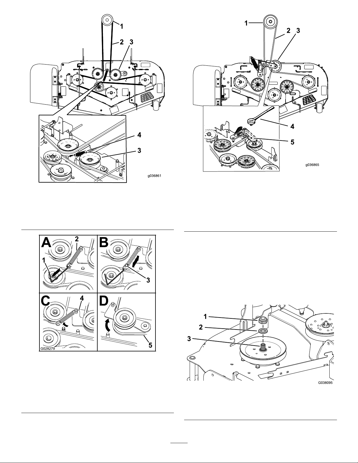
Figure7
ForModels78401,78402,and78403
1.Clutchpulley3.Spring-loadedidlerpulley
2.Mowerbelt
4.Spring
g036865
g036861
1.Clutchpulley
2.Mowerbelt
3.Spring-loadedidlerpulley
ForModels78404,78405,and78406
Figure9
4.Ratchet
5.Squareholeintheidler
armfortheratchet
2.Removethebeltfromtherightmower-deck
pulley.
3.Useawrench(1-1/2inches)toholdthespindle
shaft,asyouremovethelocknut(3/4inch)and
washerfromthespindleshaft(Figure10).
Note:Setasidethelocknut(3/4inch)and
washerforblowerModels78404,78405,and
78406.
Figure8
ForModels78401,78402,and78403
1.Spring-removaltool(T oro
PartNo.92-5771)
2.Idlerspring5.Mowerbelt
3.Mower-deckpost
4.Idlerarm
g028279
g038095
Figure10
1.Locknut(3/4inch)3.Rightspindleshaft
2.Washer
8
Page 9

4.Useawrench(1-1/2inches)toholdthespindle
shaft,asyouinstallthedoublepulleyontothe
rightspindleshaft.
•ForblowerModels78401,78402,and
78403,performthefollowingprocedure:
•ForblowerModels78404,78405,and
78406,performthefollowingprocedure:
A.Insertthethreadedstudsonpulley
mountthroughtheholesinthedeck
pulley(Figure12).
A.Usethelocknut(3/4inch)andwasherto
B.Torquethelocknut(3/4inch)to176to
1.Locknut(3/4inch)
2.Washer
securethenewdoublepulleyontothe
rightspindleshaft(Figure11).
217N∙m(130to160ft-lb).
Figure11
3.Doublepulley
4.Rightspindleshaft
B.Usethelocknut(3/4inch)andwasher
thatyousetasideearliertosecurethe
deckpulleytothespindleshaft(Figure
12).
C.Torquethelocknut(3/4inch)to176to
217N∙m(130to160ft-lb).
D.Arrangetheblowerpulleyontothe
threadedstudsandlooselyinstallthe
locknut(Figure12).
E.Rotatetheblowerpulleyclockwiseuntil
itstops.
F.Torquethe3locknutsto18N∙m(13
ft-lb).
g038253
9
Page 10

6.Installthemowerbeltaroundthelowerpulleyof
thedoublepulley(Figure13).
Figure13
1.Lowerpulley2.Mowerbelt
7.Installthebelt-coverbrackettothemowerdeck
using2carriagebolts(1/4x3/4inch)and2
locknuts(1/4inch)asshowninFigure14.
8.Installthespeednutontothebelt-coverbracket
(Figure14).
g038097
Figure12
1.Locknut(3/8inch)
2.Blowerpulley6.Pulleymount
3.Locknut(3/4inch)7.Rightspindleshaft
4.Washer
5.Existingdeckpulley
5.Ensurethatthebladeboltistorquedto115to
149N∙m(85to1 10ft-lb).
g188637
g038112
Figure14
1.Carriagebolt(1/4x3/4
inch)
2.Belt-coverbracket
3.Speednut
4.Locknut(1/4inch)
9.Installthemowerdeckbeltaroundthe
spring-loadedidlerpulley(Figure7orFigure9).
10.Usethespring-removaltool(ToroPart
No.92-5771)toattachthespringtothe
spring-loadedidlerpulley.
10
Page 11

4
InstallingtheBafe
Partsneededforthisprocedure:
1
Bafe
1
Carriagebolt(5/16x7/8inch)
1
Flangenut(5/16inch)
2
Carriagebolt(3/8x7/8inch)
2
Flangenut(3/8inch)
Procedure
1.Removethe2existingangenuts(3/8inch)and
2carriagebolts(3/8x7/8inch)fromthemower
deck(Figure15).
Figure15
1.Flangenut(3/8inch)2.Carriagebolt(3/8x7/8
inch)
2.Installthebafeusingthecarriagebolt(5/16x
7/8inch),angenut(5/16inch),2carriagebolts
(3/8x7/8inch),and2angenuts(3/8inch)as
showninFigure16.
g038289
Figure16
1.Flangenut(3/8inch)4.Flangenut(5/16inch)
2.Carriagebolt(3/8x7/8
inch)
3.Bafe
g038113
5.Carriagebolt(5/16x7/8
inch)
11
Page 12

5
InstallingtheBlower
Assembly
Partsneededforthisprocedure:
1Blowerassembly
1Blowerbelt
1Pivotpin
1Rollpin
Procedure
Verifythatthepivotpinissecuredontheblower
assemblyinthecorrectlocation(Figure17).
•Ifyouhavea48-inchor52-inchmowerdeck,
installthepivotpininthefronthole(Figure17).
•Ifyouhavea60-inchmowerdeck,installthepivot
pinintherearhole(Figure17).
1.Alignthepivotpinontheblowerwiththe
pivot-pinholeinthemowerdeck(Figure18).
Figure17
Blowerfor48-inchand52-inchmowerdeckshown
g309295
Figure18
1.Blowerassembly3.Pivothole
2.Blower-pivotpin4.Deck
2.Installthebeltaroundthepulleysinsidethe
blower(Figure19).
g309297
1.Blowerassembly4.Pivotpin
2.Fronthole(48-inchand
52-inchmowerdeck)
3.Rearhole(60-inchmower
deck)
5.Rollpin
g309298
Figure19
12
Page 13

3.Lowertheblowerandslidethepivotpinintothe
pivothole(Figure18).
Note:Ensurethatthebeltremainspositioned
intheblowerpulley.
4.Movethelatchpinfromthelockingpositionto
theopenposition(Figure20).
Figure20
g309296
1.Latchpin4.Idlerpulley
2.Chutebracket5.Belt(beneaththeidler
3.Idler-pivotbracket6.Blowerassembly
pulley)
5.Closetheblowerassemblyandalignthelatch
pinwiththeholeinthechutebracket(Figure20).
6.Movethelatchpintothelockingposition.
Note:Ensurethatthelatchpinextendsthrough
theholeinthechutebracket.
Note:Ensurethatthelatchrmlyholdsthe
blowerassemblyagainstthemowerdeck,but
youcanreleaseitbyhand.
13
Page 14

6
InstallingtheBlowerBelt
andBlower-BeltCoverl
Partsneededforthisprocedure:
1Blower-beltcover
1Knob
Procedure
1.Pullbackthespring-loadedidlerpulleyand
routetheblowerbeltaroundthedrivepulley
(Figure21).
2.Installtheblower-beltcoverovertheblowerbelt
andsecuretheblower-beltcoverwiththeknob
(Figure22).
g309587
Figure22
1.Knob2.Beltcover
Figure21
1.Blowerbelt2.Drivepulley
g309586
14
Page 15

CaliforniaProposition65WarningInformation
Whatisthiswarning?
Youmayseeaproductforsalethathasawarninglabellikethefollowing:
WARNING:CancerandReproductiveHarm—www.p65Warnings.ca.gov.
WhatisProp65?
Prop65appliestoanycompanyoperatinginCalifornia,sellingproductsinCalifornia,ormanufacturingproductsthatmaybesoldinorbroughtinto
California.ItmandatesthattheGovernorofCaliforniamaintainandpublishalistofchemicalsknowntocausecancer,birthdefects,and/orother
reproductiveharm.Thelist,whichisupdatedannually,includeshundredsofchemicalsfoundinmanyeverydayitems.ThepurposeofProp65isto
informthepublicaboutexposuretothesechemicals.
Prop65doesnotbanthesaleofproductscontainingthesechemicalsbutinsteadrequireswarningsonanyproduct,productpackaging,orliteraturewith
theproduct.Moreover,aProp65warningdoesnotmeanthataproductisinviolationofanyproductsafetystandardsorrequirements.Infact,the
CaliforniagovernmenthasclariedthataProp65warning“isnotthesameasaregulatorydecisionthataproductis‘safe’or‘unsafe.’”Manyofthese
chemicalshavebeenusedineverydayproductsforyearswithoutdocumentedharm.Formoreinformation,gotohttps://oag.ca.gov/prop65/faqs-view-all
AProp65warningmeansthatacompanyhaseither(1)evaluatedtheexposureandhasconcludedthatitexceedsthe“nosignicantrisklevel”;or(2)
haschosentoprovideawarningbasedonitsunderstandingaboutthepresenceofalistedchemicalwithoutattemptingtoevaluatetheexposure.
Doesthislawapplyeverywhere?
Prop65warningsarerequiredunderCalifornialawonly.ThesewarningsareseenthroughoutCaliforniainawiderangeofsettings,includingbutnot
limitedtorestaurants,grocerystores,hotels,schools,andhospitals,andonawidevarietyofproducts.Additionally ,someonlineandmailorder
retailersprovideProp65warningsontheirwebsitesorincatalogs.
.
HowdotheCaliforniawarningscomparetofederallimits?
Prop65standardsareoftenmorestringentthanfederalandinternationalstandards.TherearevarioussubstancesthatrequireaProp65warning
atlevelsthatarefarlowerthanfederalactionlimits.Forexample,theProp65standardforwarningsforleadis0.5μg/day,whichiswellbelow
thefederalandinternationalstandards.
Whydon’tallsimilarproductscarrythewarning?
•ProductssoldinCaliforniarequireProp65labellingwhilesimilarproductssoldelsewheredonot.
•AcompanyinvolvedinaProp65lawsuitreachingasettlementmayberequiredtouseProp65warningsforitsproducts,butothercompanies
makingsimilarproductsmayhavenosuchrequirement.
•TheenforcementofProp65isinconsistent.
•CompaniesmayelectnottoprovidewarningsbecausetheyconcludethattheyarenotrequiredtodosounderProp65;alackofwarningsfora
productdoesnotmeanthattheproductisfreeoflistedchemicalsatsimilarlevels.
WhydoesToroincludethiswarning?
Torohaschosentoprovideconsumerswithasmuchinformationaspossiblesothattheycanmakeinformeddecisionsabouttheproductstheybuyand
use.T oroprovideswarningsincertaincasesbasedonitsknowledgeofthepresenceofoneormorelistedchemicalswithoutevaluatingthelevelof
exposure,asnotallthelistedchemicalsprovideexposurelimitrequirements.WhiletheexposurefromT oroproductsmaybenegligibleorwellwithinthe
“nosignicantrisk”range,outofanabundanceofcaution,TorohaselectedtoprovidetheProp65warnings.Moreover,ifT orodoesnotprovidethese
warnings,itcouldbesuedbytheStateofCaliforniaorbyprivatepartiesseekingtoenforceProp65andsubjecttosubstantialpenalties.
RevA
Page 16

 Loading...