

Toro 78355 Operator's Manual

Wheel Horse
42” Recycler
for
FORM NO. 3318–953
Garden Tractor
Model No. 78355 – 7900001 & Up
Operator’s Manual
IMPORTANT: Read this manual carefully. It contains information about your
safety and the safety of others. Also become familiar with the controls and
their proper use before you operate the product.
Introduction
We want you to be completely satisfied with your
new product, so feel free to contact your local
Authorized Service Dealer for help with service,
genuine replacement parts, or other information you
may require.
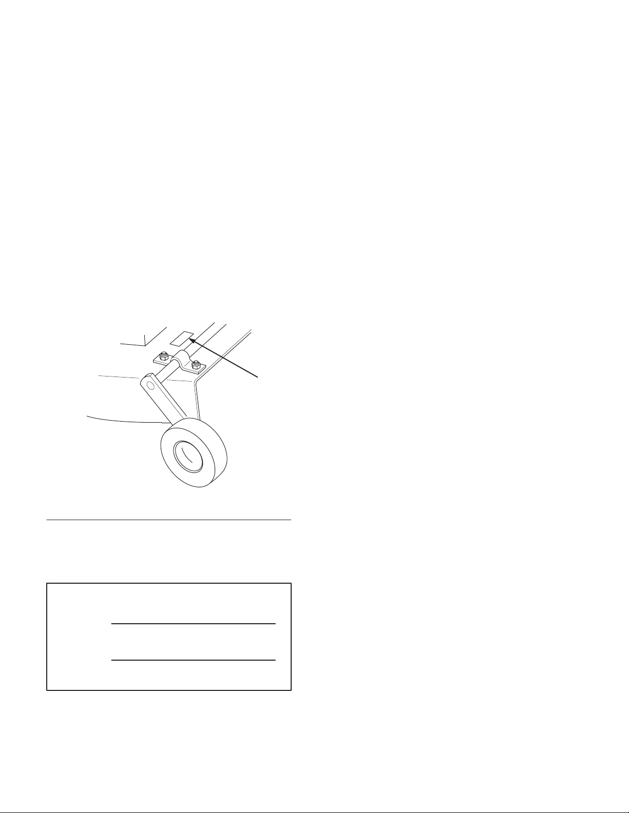
Whenever you contact your Authorized Service
Dealer or the factory, always know the model and
serial numbers of your product. These numbers will
help the Service Dealer or Service Representative
provide exact information about your specific
product. You will find the model and serial number
plate located in a unique place on the product as
shown below.
1
The warning system in this manual identifies
potential hazards and has special safety messages that
help you and others avoid personal injury, even death.
DANGER, WARNING and CAUTION are signal
words used to identify the level of hazard. However,
regardless of the hazard, be extremely careful.
DANGER signals an extreme hazard that will cause
serious injury or death if the recommended
precautions are not followed.
WARNING signals a hazard that may cause serious
injury or death if the recommended precautions are
not followed.
CAUTION signals a hazard that may cause minor or
moderate injury if the recommended precautions are
not followed.
Two other words are also used to highlight
information. “Important” calls attention to special
mechanical information and “Note” emphasizes
general information worthy of special attention.
m–2831
1. Model and Serial Number Plate
For your convenience, write the product model and
serial numbers in the space below.
Model No:
Serial No.
The left and right side of the machine is determined
by sitting on the seat in the normal operator’s
position.
Printed in USA
The TORO Co. – 1997

Contents
Safety and Instruction Decals 2. . . . . . . . . . . . . .
Assembly 3. . . . . . . . . . . . . . . . . . . . . . . . . . . . . .
Loose Parts 3. . . . . . . . . . . . . . . . . . . . . . . . .
Attach Height-of-Cut Lever 3. . . . . . . . . . . .
Attach Adjustable Link 3. . . . . . . . . . . . . . .
Installing the Mower 4. . . . . . . . . . . . . . . . .
Front-to-Rear Blade Slope 6. . . . . . . . . . . . .
Transport Height Adjustment 7. . . . . . . . . . .
Removing the Mower 8. . . . . . . . . . . . . . . . .
Operation 10. . . . . . . . . . . . . . . . . . . . . . . . . . . . . .
Operating the Power Take Off (PTO) 10. . . .
Attachment Lift Lever 10. . . . . . . . . . . . . . . .
Page
Page
Attachment Power Lift 11. . . . . . . . . . . . . . . .
Adjusting Height-of-Cut 11. . . . . . . . . . . . . .
Tips for Mowing Grass 12. . . . . . . . . . . . . . .
Maintenance 13. . . . . . . . . . . . . . . . . . . . . . . . . . . .
Service Interval Chart 13. . . . . . . . . . . . . . . .
Cutting Blade 14. . . . . . . . . . . . . . . . . . . . . . .
Greasing and Lubrication 16. . . . . . . . . . . . . .
Blade Drive Belt 16. . . . . . . . . . . . . . . . . . . . .
Power Take Off (PTO) Belt 17. . . . . . . . . . . .
Storage 18. . . . . . . . . . . . . . . . . . . . . . . . . . . .
Troubleshooting 19. . . . . . . . . . . . . . . . . . . . . . . . .
1
Safety
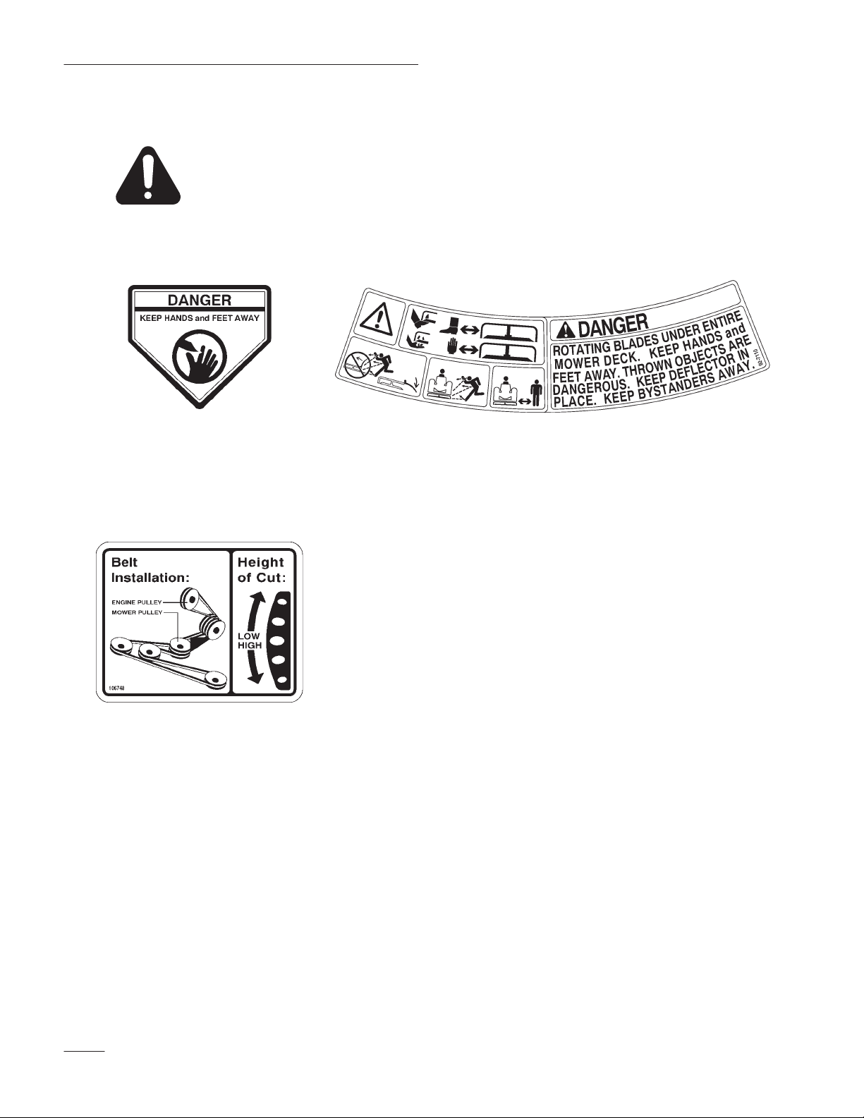
Safety and Instruction Decals
Safety decals and instructions are easily visible to the operator and are located near
any area of potential danger. Replace any decal that is damaged or lost.
ON LEFT AND RIGHT
REAR OF MOWER
(Part No. 43–8480)
NEXT TO H-O-C LEVER
(Part No. 106748)
ON MOWER LEFT AND
RIGHT SIDES
(Part No. 92–7110)
2
Assembly
Loose Parts
Note: Use the chart below to identify parts used for assembly.
DESCRIPTION QTY. USE
Height-of-cut lever
Spring
V belt
Idler assembly
Belt cover
Locknut
Operator’s Manual 1 Read before operating
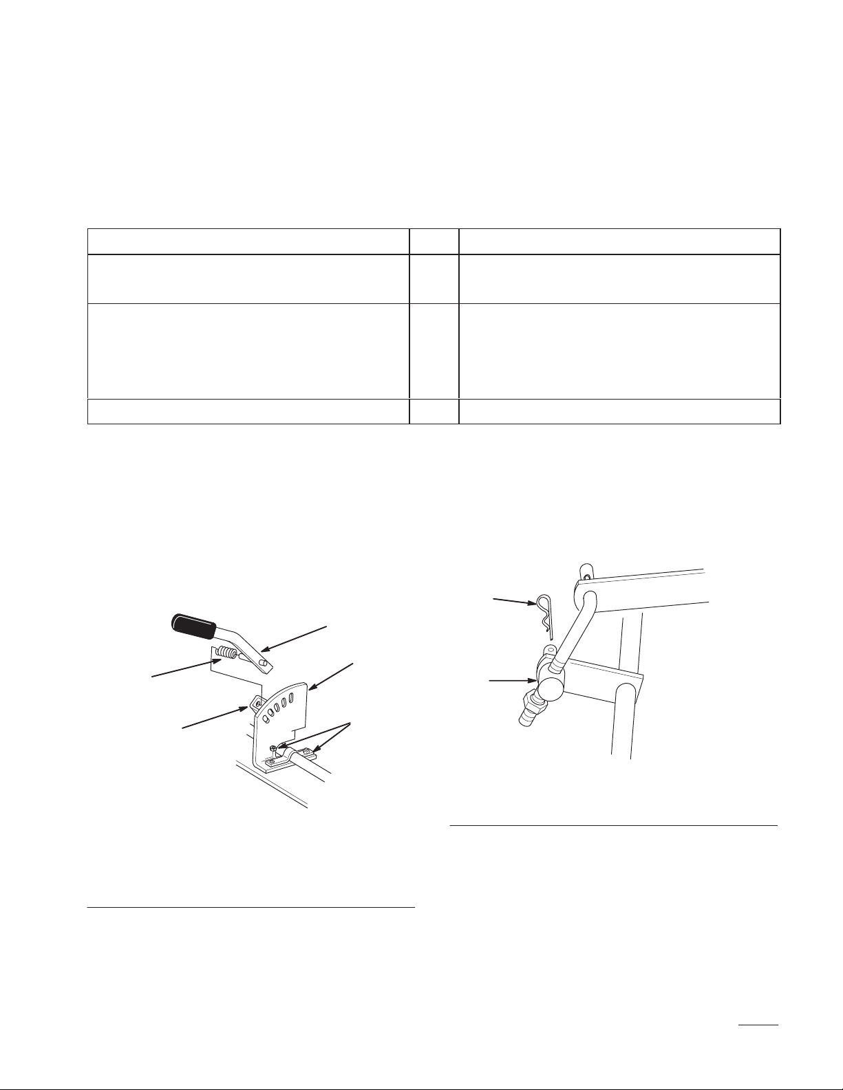
Attach Height-of-Cut Lever
1. Loosen nuts securing quadrant to mower(Fig. 1).
1
Install height-of-cut lever
1
1
1
Install mower to tractor
1
1
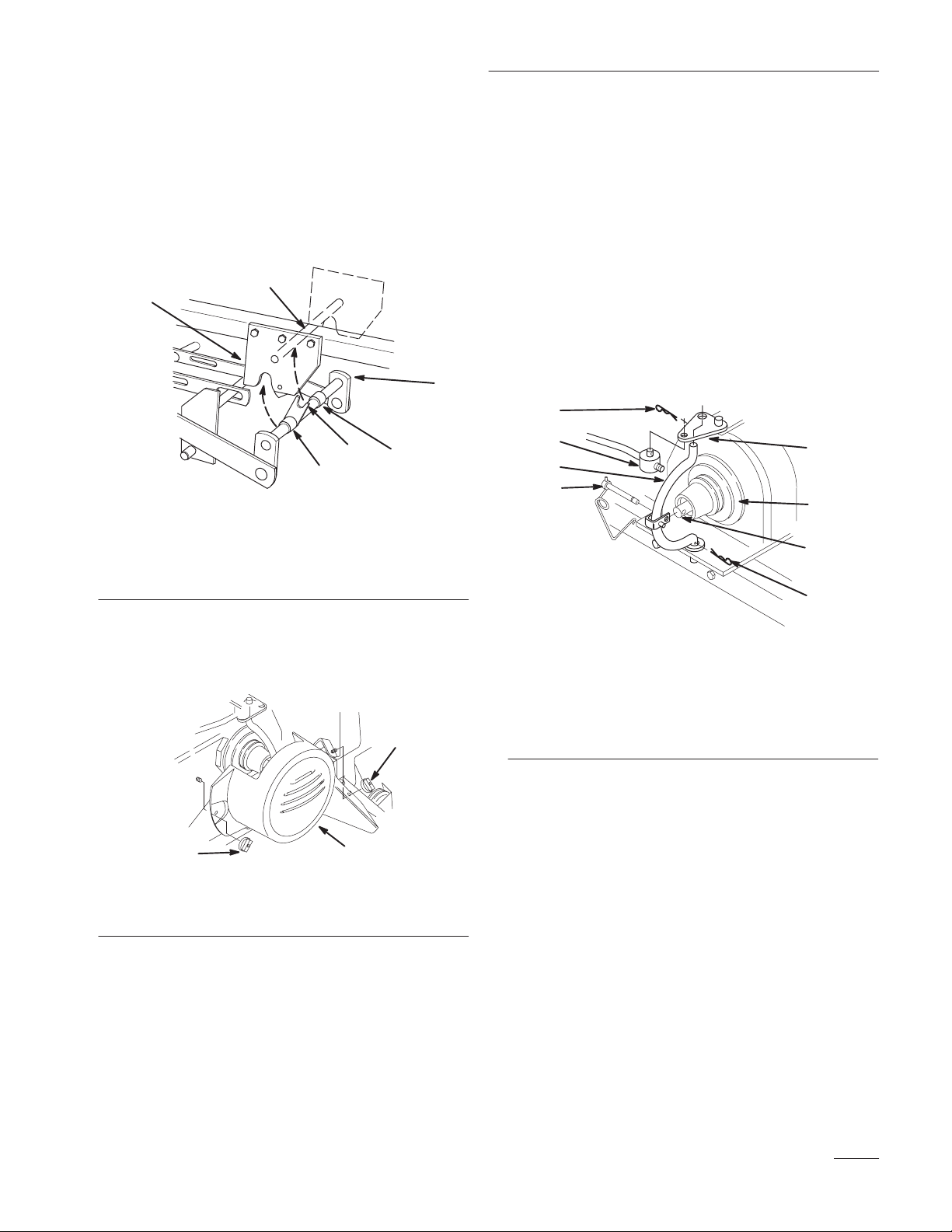
Attach Adjustable Link
1. Place adjustable link trunnion into rear wheel
shaft bracket and secure with hairpin cotter
2. Place spring onto long pin of lever. Compress
(Fig. 2).
spring and slide lever into square tube. Insert
short pin of lever into a quadrant hole hold in
position. Tighten quadrant nuts (Fig. 1).
3
2
4
2
1
5
1. Nut
2. Quadrant
3. Height-of-Cut lever
Figure 1
4. Spring
5. Square tube
1
m–2834
m–2815
Figure 2
1. Adjustable link trunnion 2. Hairpin cotter
3
Assembly
Installing the Mower
1. Park the machine on a level surface, disengage
the power take off (PTO), set the parking brake,
and turn the ignition key to “OFF” to stop the
engine. Remove the key.
2. Turn the front wheels fully to the left and raise
attachment lift lever all the way to the latched
position; refer to tractor Operator’s Manual.
3. Open front and mid-mount hitches by pushing
release button and moving lock handles forward
(Fig. 3).
2
3
1
3
m–2312
1. Front hitch
2. Mid-mount hitch
4
Figure 3
3. Release button
4. Lock handle
4. Slide the mower under the chassis from the right
side and align attachment lift with slot in center
lever bar (Fig. 4).
5. Straighten the front wheels, turn Dial-A-Height
knob counterclockwise, all the way, and lower
the attachment lift lever to the mounting
position; refer to tractor Operator’s Manual.
6. Place attachment lift pin into slot in center lever
bar and secure with 3/4” (19 mm) washer and
hairpin cotter (Fig. 4).
1
2
4
3
4
m–2824
Figure 4
1. Attachment lift
2. Slot-center level bar
3. Washer
4. Hair pin cotter
4
Assembly
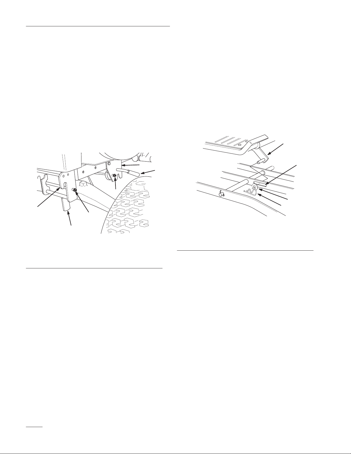
7. Rotate front mounting shaft so fork faces up and
align so spacers are between mid-mount hitch
plates (Fig. 5).
8. Lift mower with attachment lift and guide fork
to capture hitch rod (Fig. 5). Close mid-mount
hitch lock handle.
5
4
1
2
3
m–2825
1. Front mounting shaft
2. Fork
3. Spacer
3
Figure 5
4. Mid-mount hitch plate
5. Hitch rod
10. Remove hairpin cotters from trunnion and
bottom of yoke (Fig. 7).
11. Unlatch and remove locking clevis pin that
secures yoke assembly to clutch shaft. Pivot
yoke out and forward to remove from clutch
shaft and engagement plate (Fig. 7).
12. Place belt in inside pulley groove (Fig. 7).
13. Assemble yoke and engagement plate and attach
locking clevis pin, trunnion and hairpin cotters
to secure (Fig. 7).
1
2
5
4
3
7
6
1
m–2691
9. Remove the two wing nuts and belt cover from
the tractor (Fig. 6).
2
2
Figure 6
1. Belt cover 2. Wing nut
m–25341
Figure 7
1. Hairpin cotter
2. Trunnion
3. Engagement plate
4. Locking clevis pin
5. Yoke
6. Clutch shaft
7. Inside groove
14. Place pulley assembly into front hitch and lock
by moving latch rearward (Fig. 8).
5
Assembly
2
3
1
m–2810
Figure 8
1. Pulley assembly
2. Front hitch
3. Latch
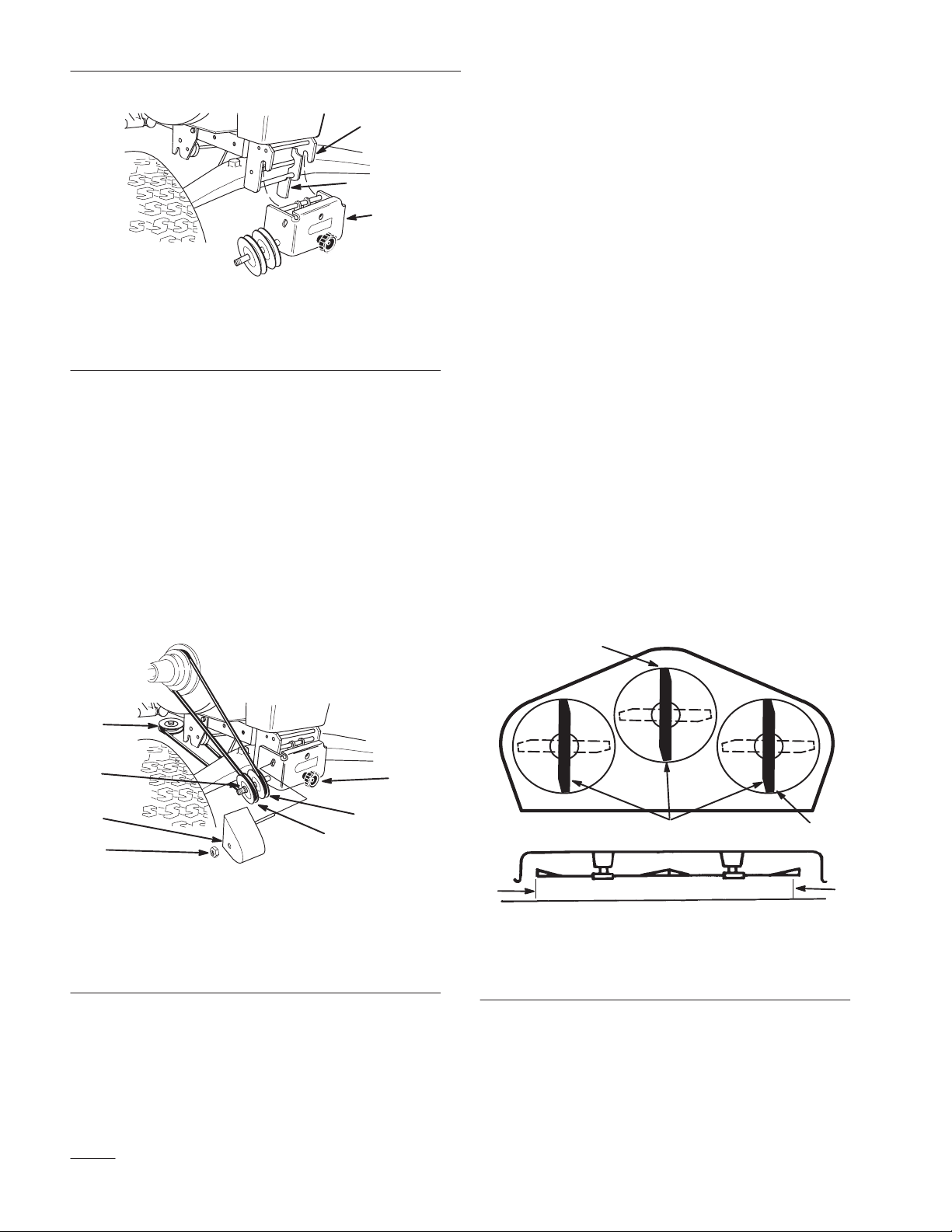
15. Route belt around V and flat pulleys and loop
over center mower spindle, top pulley.(Fig. 9).
16. Check that spacer is on shaft and install belt
cover with rod in hole. Secure with locknut
(Fig. 9).
17. Turn knob counterclockwise to tighten belt
(Fig. 9). Tighten until there is 1” (26 mm) belt
movement between engine clutch and idler
pulley when slight pressure is applied to the belt.
Front-to-Rear Blade Slope
Check the front-to-rear blade slope any time you
install the mower. Before checking the slope, set air
pressure in the front and rear tires to 12 psi (.85 kPa).
If the front blade tip is not 1/8–1/4” (4–7 mm) lower
than the rear blade tip, adjust the blade slope using
the following instructions:
1. Park the machine on a level surface, disengage
the power take off (PTO), set the parking brake,
and turn the ignition key to “OFF” to stop the
engine. Remove the key.
2. Adjust height-of-cut lever on mower to the
middle of the range and lower attachment lift.
3. Carefully rotate blades so they are facing front
and rear (Fig. 10).
4. Measure between the tip of the front blade
(Fig. 10) and the tip of the rear blade to the flat
surface. If the front blade tip is not 1/8–1/4”
(4–7 mm) lower than the rear blade tip adjust
rear adjustment link.
2
Front
m–2833
3
4
5
6
Figure 9
1. V pulley
2. Flat pulley
3. Upper mower pulley
4. Spacer
18. Install belt cover (Fig. 6).
6
2
5. Belt cover
6. Locknut
7. Knob
7
1
1
m–2823
4
3
4
Figure 10
1. Blade front to rear
2. Measure front blade tip
3. Measure rear blade tip
4. Measure here
 Loading...