

Page 1

FORM NO. 3318–948 Rev. A
Wheel
Horse
42” Rear Discharge
Mower
for
Classic
Model No. 78350 – 7900001 & Up
Garden T
ractors
Operator’s Manual
IMPORTANT: Read this manual carefully. It contains information about your
safety and the safety of others. Also become familiar with the controls and
their proper use before you operate the product.
Page 2
Introduction
We want you to be completely satisfied with your
new product, so feel free to contact your local
Authorized Service Dealer for help with service,
genuine replacement parts, or other information you
may require.
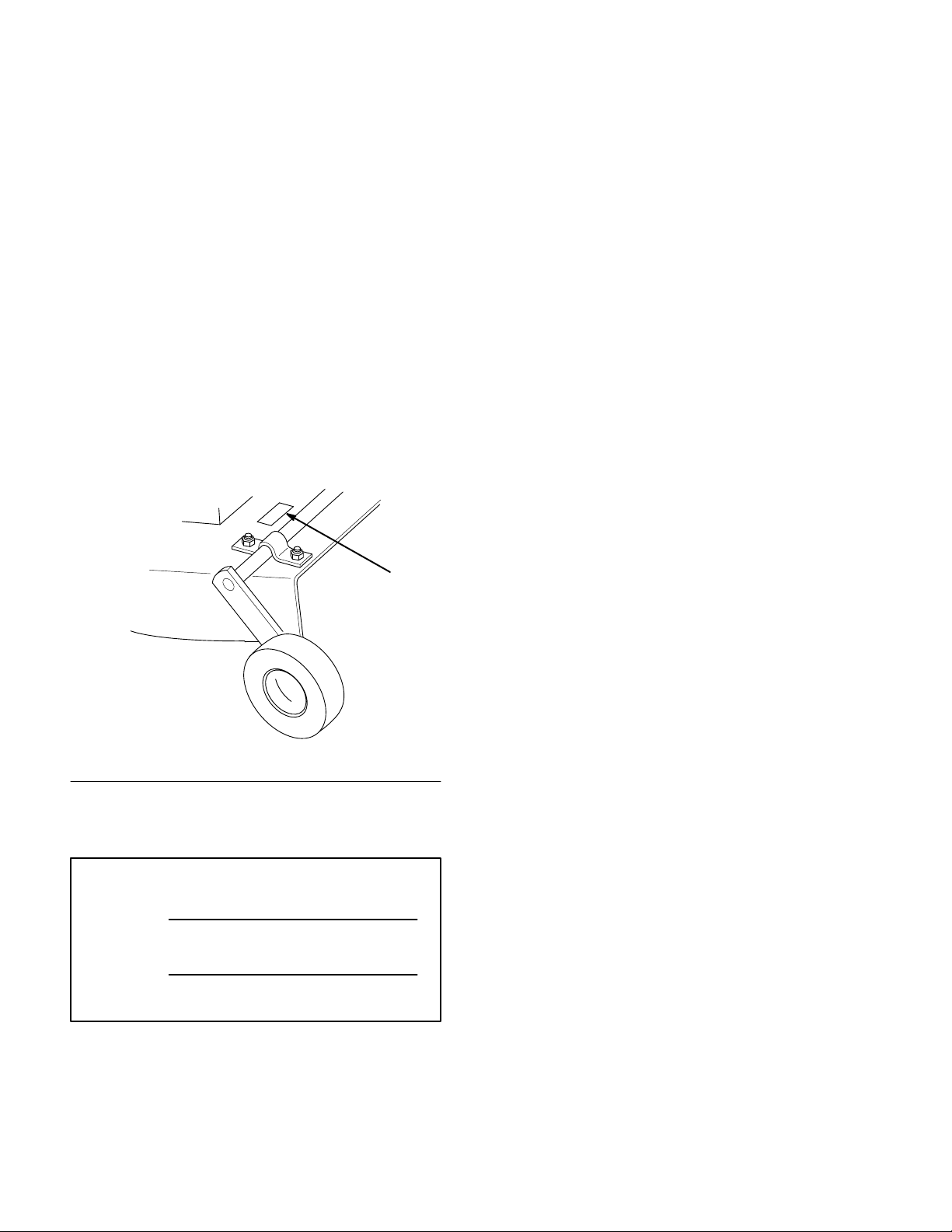
Whenever you contact your Authorized Service
Dealer or the factory, always know the model and
serial numbers of your product. These numbers will
help the Service Dealer or Service Representative
provide exact information about your specific
product. You will find the model and serial number
plate located in a unique place on the product as
shown below
.
1
The warning system in this manual identifies
potential hazards and has special safety messages that
help you and others avoid personal injury, even death.
DANGER, WARNING and CAUTION are signal
words used to identify the level of hazard. However,
regardless of the hazard, be extremely careful.
DANGER signals an extreme hazard that will cause
serious injury or death if the recommended
precautions are not followed.
WARNING signals a hazard that may cause serious
injury or death if the recommended precautions are
not followed.
CAUTION signals a hazard that may cause minor or
moderate injury if the recommended precautions are
not followed.
Two other words are also used to highlight
information. “Important” calls attention to special
mechanical information and “Note” emphasizes
general information worthy of special attention.
m–2831
1. Model
For your convenience, write the product model and
serial numbers in the space below.
Model No:
Serial No.
and Serial Number Plate
The left and right side of the machine is determined
by sitting on the seat in the normal operator’s
position.
Printed in USA
The TORO Co. – 1996
Page 3

Contents
Page
Safety and Instruction Decals 2.
Assembly 3
Operation 10
. . . . . . . . . . . . . . . . . . . . . . . . . . . . . .
Loose Parts 3
Attach Height-of-Cut Lever 3
Attach Adjustable Link 3
Installing the Mower 4
Front-to-Rear Blade Slope 6
Transport Height Adjustment 7
Removing the Mower 8
Operating the Power Take Off (PTO) 10
Attachment Lift Lever 10
. . . . . . . . . . . . . . . . . . . . . . . . .
. . . . . . . . . . . . . . . . . . . . . . . . . . . . . .
. . . . . . . . . . . . .
. . . . . . . . . . . .
. . . . . . . . . . . . . . .
. . . . . . . . . . . . . . . . .
. . . . . . . . . . . . .
. . . . . . . . . . .
. . . . . . . . . . . . . . . . .
. . . .
. . . . . . . . . . . . . . . .
Page
Attachment Power Lift 11
Adjusting Height-of-Cut 11
Tips for Mowing Grass 12
Maintenance 13
Service Interval Chart 13
Cutting Blade14. . . . . . . . . . . . . . . . . . . . . . .
Greasing and Lubrication 16
Blade Drive Belt 16
Power Take Off (PTO) Belt 17
Storage 18
Troubleshooting 19
. . . . . . . . . . . . . . . . . . . . . . . . . . . .
. . . . . . . . . . . . . . . . . . . . . . . . . . . .
. . . . . . . . . . . . . . . . . . . . . . . . .
. . . . . . . . . . . . . . . .
. . . . . . . . . . . . . .
. . . . . . . . . . . . . . .
. . . . . . . . . . . . . . . .
. . . . . . . . . . . . . .
. . . . . . . . . . . . . . . . . . . . .
. . . . . . . . . . . .
1
Page 4
Safety
Safety
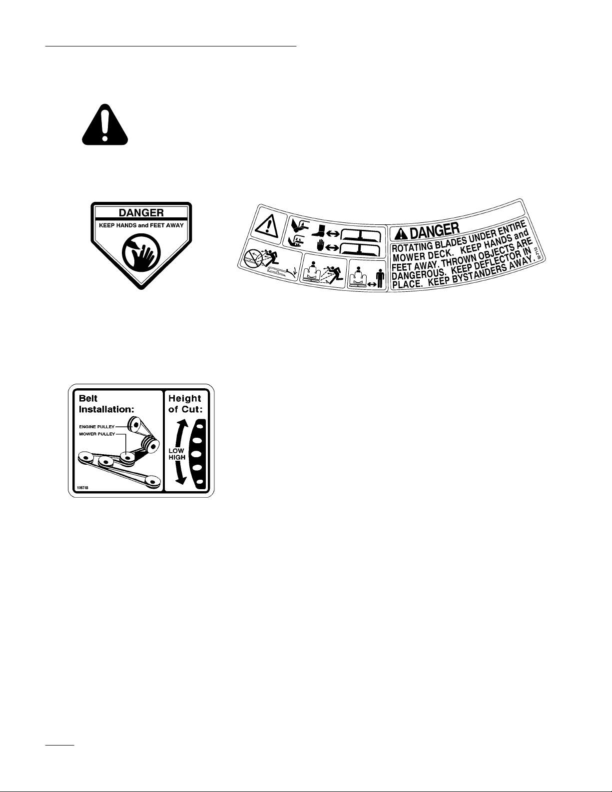
and Instruction Decals
Safety decals and instructions are easily visible to the operator and are located near
any area of potential danger. Replace any decal that is damaged or lost.
ON LEFT AND RIGHT
REAR OF MOWER
(Part No. 43–8480)
NEXT T
O H-O-C LEVER
(Part No. 106748)
ON MOWER LEFT AND
RIGHT SIDES
(Part No. 92–71
10)
2
Page 5
Assembly
Loose
Parts
Note: Use the chart below to identify parts used for assembly.
DESCRIPTION QTY. USE
Height-of-cut lever
Spring
V belt
Idler assembly
Belt cover
Locknut
Operator’
Attach
s Manual
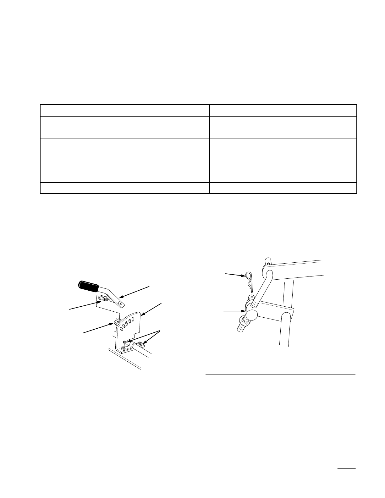
Height-of-Cut Lever
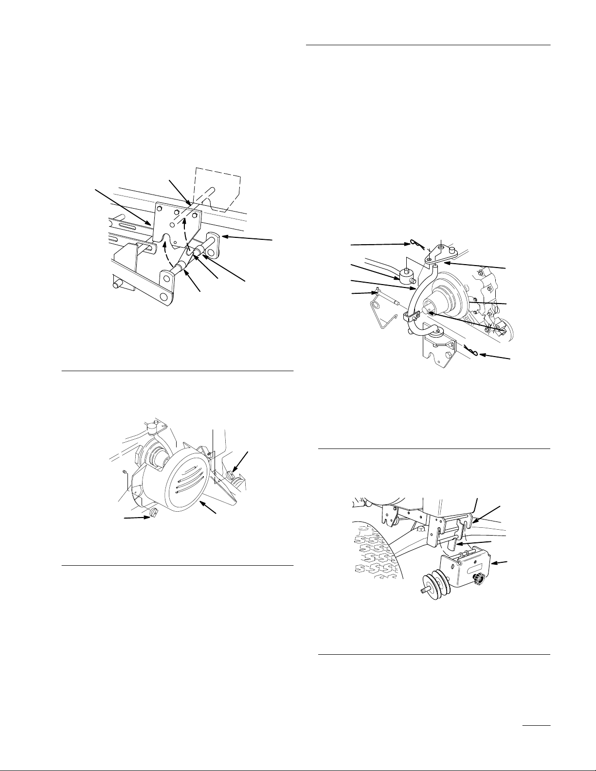
1. Loosen nuts securing quadrant to mower(Fig. 1).
1
1
1
1
1
1
1
Install height-of-cut lever
Install mower to tractor
Read before operating
Attach
Adjustable Link
1. Place adjustable link trunnion into rear wheel
shaft bracket and secure with hairpin cotter
2. Place spring onto long pin of lever
. Compress
(Fig. 2).
spring and slide lever into square tube. Insert
short pin of lever into a quadrant hole hold in
position. Tighten quadrant nuts (Fig. 1).
2
4
1. Nut
2. Quadrant
3. Height-of-Cut
5
lever
Figure 1
4. Spring
5.
Square tube
3
2
1
1
m–2815
Figure 2
m–2834
1. Adjustable
link trunnion
2.
Hairpin cotter
3
Page 6
Assembly
Installing
the Mower
1. Park the machine on a level surface, disengage
the power take off (PTO), set the parking brake,
and turn the ignition key to “OFF” to stop the
engine. Remove the key.
2. Turn the front wheels fully to the left and raise
attachment lift lever all the way to the latched
position; refer to tractor Operator’
s Manual.
3. Open front and mid-mount hitches by pushing
release button and moving lock handles forward
(Fig. 3).
2
3
1
3
m–2312
1. Front
2.
hitch
Mid-mount hitch
4
Figure 3
3.
Release button
4.
Lock handle
4. Slide the mower under the chassis from the right
side and align attachment lift with slot in center
lever bar (Fig. 4).
5. Straighten the front wheels, turn Dial-A-Height
knob counterclockwise, all the way, and lower
the attachment lift lever to the mounting
position; refer to tractor Operator’
s Manual.
6. Place attachment lift pin into slot in center lever
bar and secure with 3/4” (19 mm) washer and
hairpin cotter (Fig. 4).
1
2
4
3
4
m–2824
Figure 4
1. Attachment
2.
Slot-center level bar
lift
3. Washer
4.
Hair pin cotter
4
Page 7
Assembly
7. Rotate front mounting shaft so fork faces up and
align so spacers are between mid-mount hitch
plates (Fig. 5).
8. Lift mower with attachment lift and guide fork
to capture hitch rod (Fig. 5). Close mid-mount
hitch lock handle.
5
4
1
2
3
3
m–2825
Figure 5
1. Front
2. Fork
3. Spacer
mounting shaft
4.
Mid-mount hitch plate
5.
Hitch rod
9. Remove the two wing nuts and belt cover from
the tractor (Fig. 6).
2
10. Remove hairpin cotters from trunnion and
bottom of yoke (Fig. 7).
11. Unlatch and remove locking clevis pin that
secures yoke assembly to clutch shaft. Pivot
yoke out and forward to remove from clutch
shaft and engagement plate (Fig. 7).
12. Place belt in inside pulley groove (Fig. 7).
13. Assemble yoke and engagement plate and attach
locking clevis pin, trunnion and hairpin cotters
to secure (Fig. 7).
1
2
5
4
1. Hairpin
2. Trunnion
3.
4.
cotter
Engagement plate
Locking clevis pin
Figure 7
5. Yoke
6.
Clutch shaft
7.
Inside groove
3
7
6
1
m–3443
6. Belt
cover
14. Place pulley assembly into front hitch and lock
by moving latch rearward (Fig. 8).
2
2
Figure 6
7.
Wing nut
m–25341
3
1
m–2810
Figure 8
1. Pulley
2.
assembly
Front hitch
3. Latch
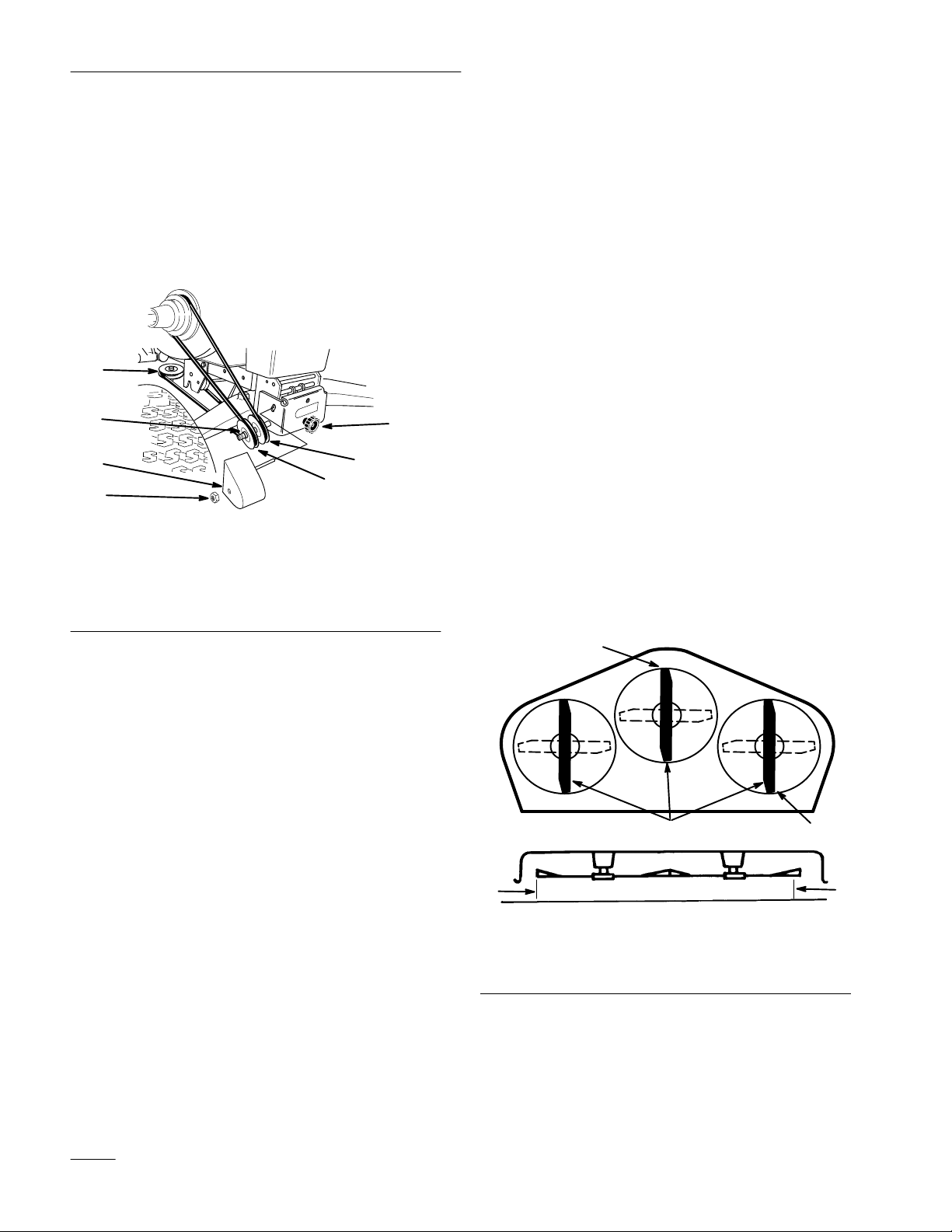
15. Route belt around V and flat pulleys and loop
over center mower spindle, top pulley.(Fig. 9).
5
Page 8
Assembly
16. Check that spacer is on shaft and install belt
cover with rod in hole. Secure with locknut
(Fig. 9).
17. Turn knob counterclockwise to tighten belt
(Fig. 9). Tighten until there is 1” (26 mm) belt
movement between engine clutch and idler
pulley when slight pressure is applied to the belt.
3
4
5
6
1. V
pulley
2.
Flat pulley
3.
Upper mower pulley
4. Spacer
Figure 9
Belt cover
5.
6. Locknut
7. Knob
1
2
7
m–2823
Front-to-Rear
Blade Slope
Check the front-to-rear blade slope any time you
install the mower. Before checking the slope, set air
pressure in the front and rear tires to 12 psi (.85 kPa).
If the front blade tip is not 1/8–1/4” (4–7 mm) lower
than the rear blade tip, adjust the blade slope using
the following instructions:
1. Park the machine on a level surface, disengage
the power take off (PTO), set the parking brake,
and turn the ignition key to “OFF” to stop the
engine. Remove the key.
2. Adjust height-of-cut lever on mower to the
middle of the range and lower attachment lift.
3. Carefully rotate blades so they are facing front
and rear (Fig. 10).
4. Measure between the tip of the front blade
(Fig. 10) and the tip of the rear blade to the flat
surface. If the front blade tip is not 1/8–1/4”
(4–7 mm) lower than the rear blade tip adjust
rear adjustment link.
18. Install belt cover (Fig. 6).
4
1. Blade
2.
front to rear
Measure front blade tip
2
1
m–2833
3
4
Figure 10
3.
Measure rear blade tip
4.
Measure here
6
Page 9

Assembly
5. To adjust front-to rear blade slope turn locknut
on rear adjustable link (Fig. 11).
Note: To raise the front of the mower, turn
locknut clockwise, to lower front turn
counterclockwise.
1
2
m–2815
1. Adjustable
Figure 1
link
1
2. Locknut
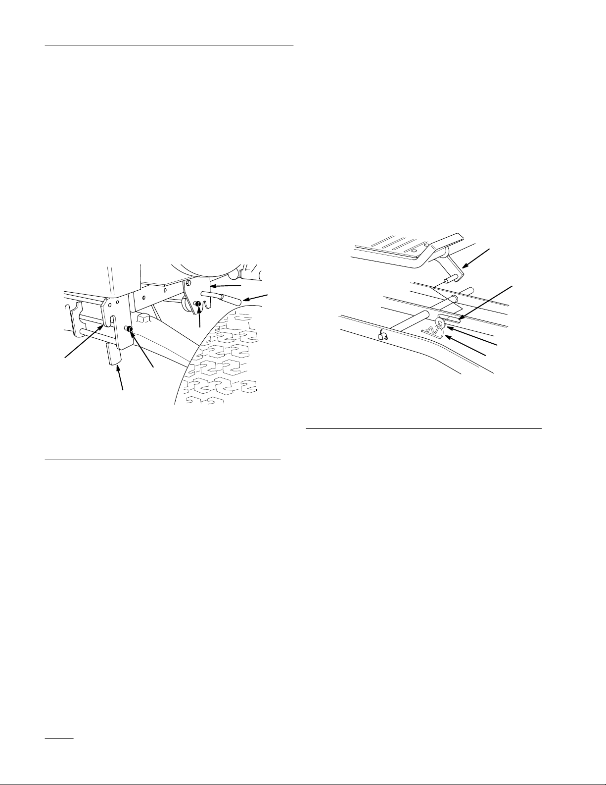
Transport
Height Adjustment
Transport height is adjusted to stabilize the mower in
the up, locked position.
1. Raise attachment lift lever all the way to the
latched position. Check if bumpers, on rear of
mower draft bars contact under footrests.
2. Adjust lift chain by turning trunnion on eyebolt
in rear hole of tractor lift (Fig. 12). Turn
trunnion clockwise to raise or counterclockwise
to lower mower.
3. Transport level stops are normally in the bottom
of the slot, however they can be adjusted up for
side-to-side level when extra weight from a grass
catcher is on one side (Fig. 12).
1
1. Bumper
2. Trunnion
Figure 12
3. Leveling
2
3
bolts
m–2813
7
Page 10

Assembly
Removing
the Mower
1. Park the machine on a level surface, disengage
the power take off (PTO), set the parking brake,
and turn the ignition key to “OFF” to stop the
engine. Remove the key.
2. Remove the two wing nuts and belt cover from
the tractor (Fig. 13).
2
m–25341
4. Belt
cover
2
Figure 13
5.
Wing nut
4. Remove hairpin cotters from trunnion and
bottom of yoke (Fig. 15).
5. Unlatch and remove locking clevis pin that
secures yoke assembly to clutch shaft. Pivot
yoke out and forward to remove from clutch
shaft and engagement plate (Fig. 15).
6. Remove belt from pulley (Fig. 15).
7. Assemble yoke and engagement plate and attach
locking clevis pin, trunnion and hairpin cotters
to secure (Fig. 15).
1
2
5
4
3
7
6
3. Turn knob on idler assembly clockwise to loosen
belt. Remove belt from upper mower pulley
(Fig. 14).
2
1
m–2823
Figure 14
1. Knob 2. Upper
mower pulley
1
m–3443
Figure 15
1. Hairpin
2. Trunnion
3.
4.
cotter
Engagement plate
Locking clevis pin
5. Yoke
6.
Clutch shaft
7.
Inside groove
8. Open front hitch and remove pulley assembly
(Fig. 16).
2
3
1
m–2810
Figure 16
1. Pulley
2.
assembly
Front hitch
3. Latch
9. Raise attachment lift lever to the mounting
position; refer to tractor Operator’
8
s Manual.
Page 11
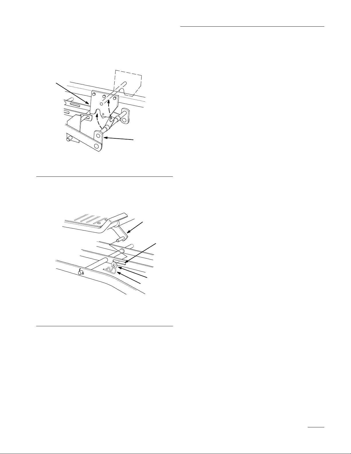
10. Open mid-mount hitch lock handle. Lower
mower with attachment lift and remove front
mounting shaft (Fig. 17).
1
2
Figure 17
1. Mid-mount
hitch
2.
Front mounting shaft
11. Remove hairpin cotter and washer from
attachment lift pin from slot in center lever bar
(Fig. 18).
Assembly
m–2825
1
2
3
4
m–2824
Figure 18
1. Attachment
2.
Slot-center level bar
lift
3. Washer
4.
Hair pin cotter
12. Turn the front wheels fully to the left and raise
attachment lift lever all the way to the latched
position; refer to tractor Operator’
s Manual.
Slide the mower out from under the chassis to
the the right side.
Note: Save all hardware, washers and hairpin
cotters for use when installing deck.
9
Page 12

Operation
Operating
Power T
The power take off (PT
power to the clutch.
While the ignition key is in “RUN” position and the
power take off (PTO) is engaged, the PTO light in the
Indicator Module, will be “ON”. When this light is
“ON” it is a reminder; the starter will not crank
the
ake Off (PT
O) engages and disengages
O)
Engaging the Power Take Off (PTO)
1. Depress the clutch and brake pedals to stop the
machine.
2. Push the power take off (PTO) lever forward to
engage (Fig. 19).
1
2
Attachment
The attachment lift lever (Fig. 20) is used to raise and
lower various attachments.
Lift Lever
Raising Attachments
1. Depress the clutch and brake pedals to stop the
machine.
2. Pull attachment lift lever rearward until latch
locks. In this position the lift will hold the
attachment in the up, or raised position.
Lowering Attachments
1. Depress the clutch and brake pedals to stop the
machine.
2. Pull attachment lift lever rearward, to release lift
pressure, and push the button on top to release
the latch. Move lift lever forward to lower
attachment.
m–3430
Figure 19
1. Engaged 2. Disengaged
Disengaging the Power Take Off (PTO)
1. Depress the clutch and brake pedals to stop the
machine.
2. Pull the power take off (PTO) lever back to
disengage (Fig. 19).
1. Lift
lever
2. Button
2
1
3
m–2514
Figure 20
3. Dial-A-Height
10
Page 13

Operation
Attachment
Power Lift
The attachment power lift (Fig. 21) is used to raise
and lower attachments.
Raising Attachments
1. Start the engine, refer to; Starting and Stopping
the Engine; in tractor Operator’
s Manual.
2. Pull the lift lever in the “UP” direction to raise
the attachment lift (Fig. 21). This will lift and
hold the attachment in the up, or raised position.
Lowering Attachments
1. Start the engine, refer to; Starting and Stopping
the Engine; in tractor Operator’
2. Push the lift lever in the “DOWN” direction to
lower the attachment lift (Fig. 21). This will
lower the attachment lift.
2
s Manual.
Adjusting
Height-of-Cut
The rear gauge wheels are adjusted in different hole
location for 1-1/2–3-1/2” (4–9 cm) height-of-cut.
1. Pull height-of-cut lever out to disengage from
quadrant. Adjust height-of-cut to the desired
level. Release lever inward to lock into quadrant
(Fig. 22).
1
3
4
2
m–2827
Figure 22
1. Height-of-cut
2. Quadrant
lever
3. Low
4. High
1. Lift
lever UP
1
Figure 21
2.
m–2317
Lift lever DOWN
11
Page 14

Operation
Tips
for Mowing Grass
Fast Throttle Setting
For best mowing and maximum air circulation,
operate the engine at “FAST.” Air is required to
thoroughly cut grass clippings, so do not set the
height-of-cut so low, as to totally surround the mower
by uncut grass. Always try to have one side of the
mower free from uncut grass, which allows air to be
drawn into the mower.
Cutting a Lawn for the First Time
Cut grass slightly longer than normal to ensure the
cutting height of the mower does not scalp any
uneven ground. However, the cutting height used in
the past is generally the best one to use. When cutting
grass longer than six inches tall, you may want to cut
the lawn twice to assure an acceptable quality-of-cut.
Cut 1/3 of the Grass Blade
It is best to cut only about 1/3 of the grass blade.
Cutting more than that is not recommended, unless
grass is sparse or it is late fall when grass grows more
slowly.
Mowing Direction
Ground Speed
To improve cut quality, use slower ground speed.
Avoid Cutting Too Low
If the cutting width of the mower is wider than the
mower you previously used, raise the cutting height
to ensure uneven turf is not cut too short.
Long Grass
If the grass is ever allowed to grow slightly longer
than normal, or if it contains a high degree of
moisture, raise the cutting height higher than usual
and cut the grass at this setting. Then cut the grass
again using the lower, normal setting.
When Stopping
If the machine’s forward motion must be stopped
while mowing, a clump of grass clippings may drop
onto your lawn. To avoid this:
1. With the blade(s) “ENGAGED,” move onto a
previously cut area.
2. To disperse the clippings evenly, raise the mower
one or two height-of-cut settings while driving
forward with the blade(s) “ENGAGED.”
Alternate mowing direction to keep the grass standing
straight. This also helps disperse clippings which
enhances decomposition and fertilization.
Mow at Correct Intervals
Normally, mow every 4 days. But remember, grass
grows at different rates at different times. So to
maintain the same cutting height, which is a good
practice, mow more often in early spring. As the
grass growth rate slows in mid summer, mow less
frequently. If you cannot mow for an extended period,
first mow at a high cutting height; then mow again 2
days later at a lower height setting.
12
Keep the Underside of the Mower Clean
Clean clippings and dirt from the underside of the
mower after each use. If grass and dirt build up inside
the mower, cutting quality will eventually become
unsatisfactory.
Blade Maintenance
Maintain a sharp blade throughout the cutting season
because a sharp blade cuts cleanly without tearing or
shredding the grass blades. Tearing and shredding
turns grass brown at the edges, which slows growth
and increases the chance of disease. Every 30 days,
check the cutter blade(s) for sharpness and file down
any nicks.
Page 15

Maintenance
Service
Service
Cutter Blade—check
Grease–Mower spindles, wheels
Belts—check for wear/cracks
Mower Housing—clean
Chipped Surfaces—paint
Interval Chart
Operation
POTENTIAL HAZARD
• If you leave the key in the ignition switch, someone could start the engine.
WHAT CAN HAPPEN
• Accidental starting of the engine could seriously injure you or other bystanders.
HOW TO AV
OID THE HAZARD
• Remove the key from the ignition switch and pull the wire off the spark plug before
you do any maintenance. Also push the wire aside so it does not accidentally contact
the spark plug.
Each
Use5Hours25Hours
X X X
X X
X X X
Storage
Service
X
X
Spring
Service
Notes
13
Page 16
Maintenance
Cutting
Blade
To assure a superior quality of cut, keep the blade(s)
sharp. For convenient sharpening and replacement,
you may want to have an extra blade(s).
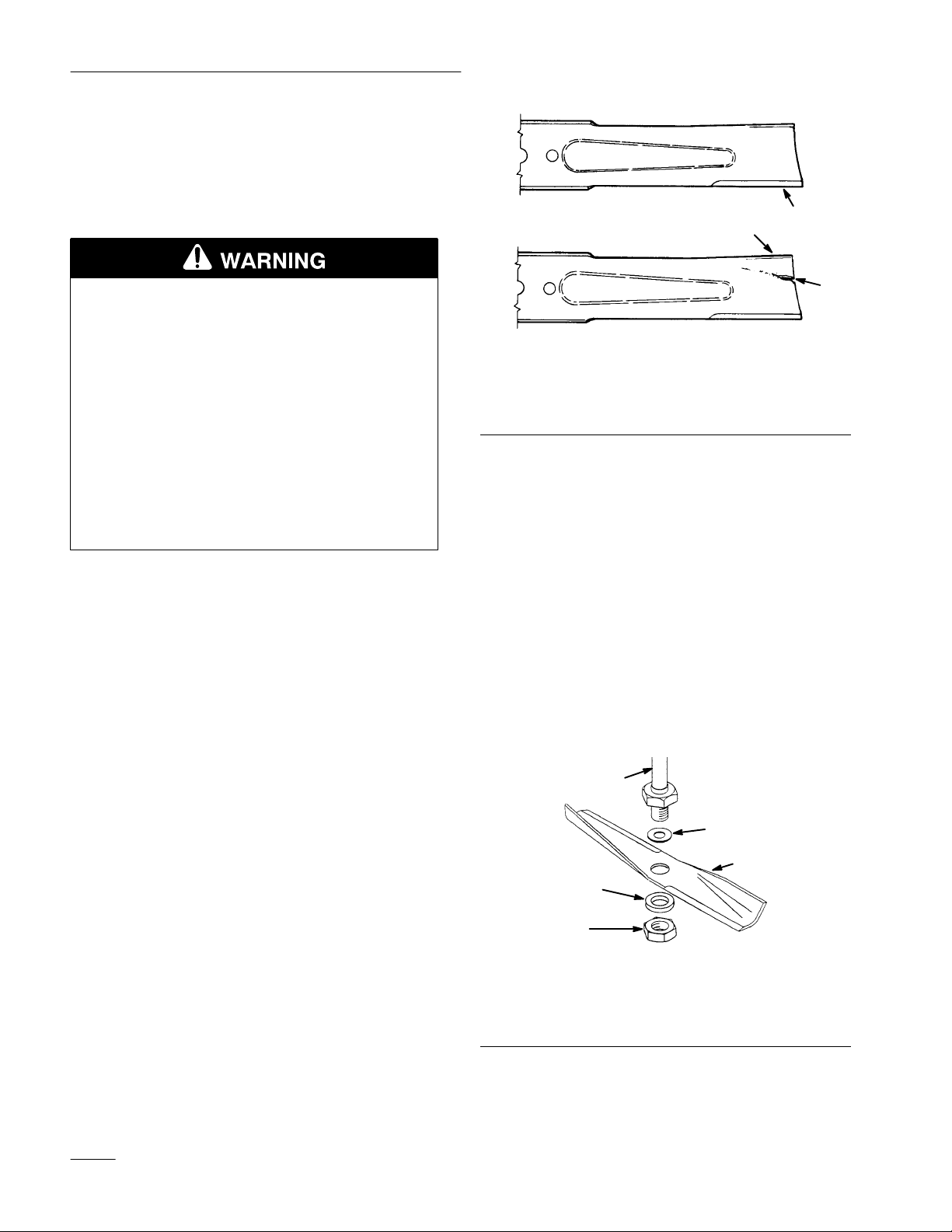
POTENTIAL HAZARD
• A blade that is worn or damaged could
break apart and pieces could be thrown at
bystanders or at you as you use the mower.
WHAT CAN HAPPEN
• Pieces of blade that may be thrown could
seriously injure or kill you or bystanders.
HOW TO AV
OID THE HAZARD
• Periodically inspect the blade for wear and
damage. Immediately install a new blade if
it is worn or damaged.
Inspecting the Blade(s)
1. Remove the mower; refer to Removing the
Mower, page 8.
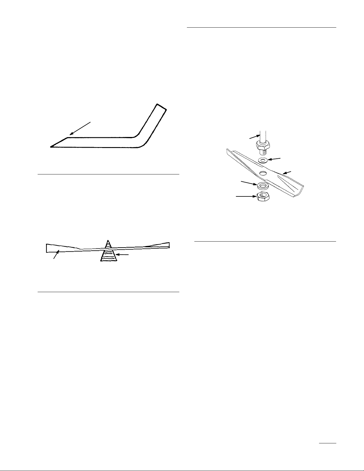
2. Inspect the cutting edges (Fig. 23). If the edges
are not sharp or have nicks, remove the blade(s)
and sharpen them; refer to Sharpening the
Blade(s), page 15.
1
3
151
1. Cutting
2.
Curved area
edge
Figure 23
3. W
2
ear/slot forming
Removing the Blade
1. Remove the mower; refer to Removing the
Mower, page 8.
2. Carefully tip the mower over.
3. Remove the nut, flat washer, blade and washer
(Fig. 24). A block of wood may be wedged
between the blade and the mower to lock the
blade when you are removing the bolt.
4. Inspect all parts. If a defect or damage is noticed,
install new parts.
3. Inspect the blade(s), especially the curved area
(Fig. 23). If you notice any damage, wear, or a
slot forming in this area (Fig. 23), immediately
install a new blade.
14
1. Nut
2. Flat
3. Blade
2
1
washer – thick
5
Figure 24
4
4. W
asher – thin
5. Spindle
3
Page 17
Maintenance
Sharpening the Blade(s)
1. Use a file to sharpen the cutting edge at both
ends of the blade (Fig. 25). Maintain the original
angle. The blade retains its balance if the same
amount of material is removed from both cutting
edges.
1
Figure 25
1. Sharpen
2. Check the balance of the blade by putting it on a
blade balancer (Fig. 26). If the blade stays in a
horizontal position, the blade is balanced and can
be used. If the blade is not balanced, file some
metal off the back side of the blade. Repeat this
procedure until the blade is balanced.
at original angle
Installing the Blade(s)
1. Install the washer, blade, flat washer, and the
blade nut (Fig. 27).
IMPORTANT: The curved part of the blade
must be pointing toward the inside of the
mower to assure proper cutting.
2. Tighten the bland nut to 80-100 ft–lb
(109-136 Nm).
5
4
3
2
1
Figure 27
1. Nut
2. Flat
3. Blade
washer – thick
4. W
asher – thin
5. Spindle
2
1
Figure 26
1. Blade 2. Balancer
15
Page 18
Maintenance
Greasing
and Lubrication
Service Interval/Specification
Grease the mower after every 25 operating hours or
once a year, whichever occurs first. Grease more
frequently when operating conditions are extremely
dusty or sandy.
Grease Type: General-purpose grease.
How to Grease
1. Disengage the power take off (PTO), set the
parking brake, and turn the ignition key to
“OFF” to stop the engine. Remove the key
2. Clean the grease fittings with a rag. Make sure to
scrape any paint off the end of the fitting(s).
3. Connect a grease gun to the fitting. Pump grease
into the fittings.
Blade
Drive Belt
Removing the Blade Drive Belt
1. Remove the mower; refer to Removing the
Mower, page 8.
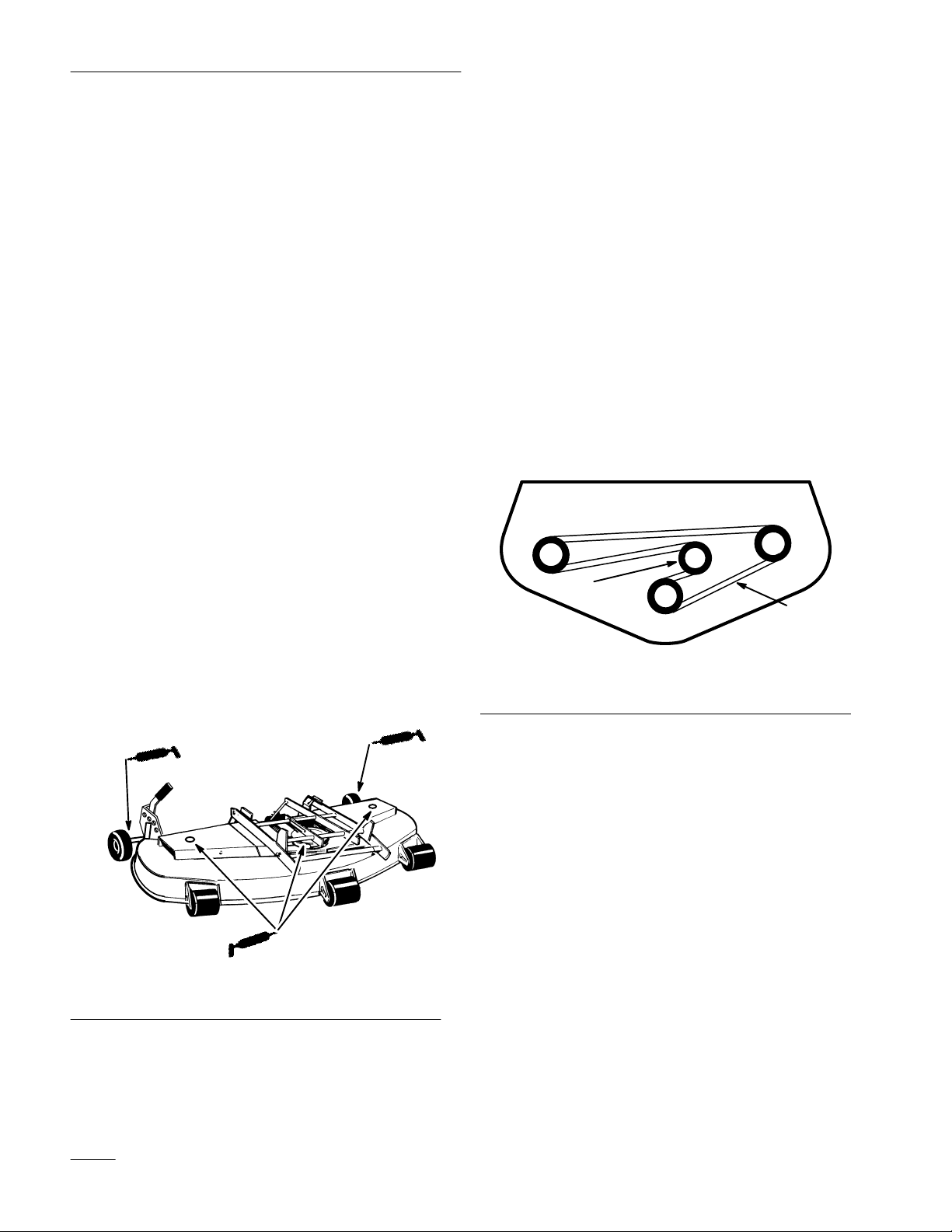
2. Remove pulley cover mounting screws and
pulley covers from both blade pulleys.
3. Push on idler to release tension and remove the
belt from the pulleys (Fig. 29).
Installing the Blade Drive Belt
1. Install the new belt around the blade pulleys and
the idler pulley (Fig. 29).
4. Wipe up any excess grease.
Where to Add Grease
1. Lubricate the blade spindle and gauge wheel
bearings (Fig. 28).
Figure 28
1
2
m–2832
Figure 29
1. Idler 2. Belt
2. Install left and right pulley covers with
previously removed mounting screws.
3. Install the mower; refer to Installing the Mower,
page 4.
M–2829
16
Page 19

Maintenance
Power Take Off (PT
O) Belt
1. Remove the two wing nuts and belt cover from
the tractor (Fig. 30).
2
2
m–25341
Figure 30
3. Belt
cover
4.
Wing nut
2. Turn knob on idler assembly clockwise to loosen
belt (Fig. 31).
3. Remove locknut and belt cover from idler
assembly. Remove belt from upper mower
pulley (Fig. 31).
4. Unlatch and remove locking clevis pin that
secures yoke assembly to clutch shaft. Pivot
yoke out and forward to remove from clutch
shaft and engagement plate (Fig. 32).
5. Replace belt in inside pulley groove (Fig. 32).
6. Assemble yoke and engagement plate and attach
locking clevis pin, trunnion and hairpin cotters
to secure (Fig. 32).
1
2
5
4
1. Hairpin
2. Trunnion
3.
4.
cotter
Engagement plate
Locking clevis pin
Figure 32
5. Yoke
6.
7.
Clutch shaft
Inside groove
3
7
6
1
m–3443
3
4
5
6
1. V
pulley
2.
Flat pulley
3.
Upper mower pulley
4. Spacer
Figure 31
5.
6. Locknut
7. Knob
2
Belt cover
7
1
m–2823
17
Page 20

Maintenance
7. Route belt around V and flat pulleys and loop
over center mower spindle, top pulley.(Fig.33).
8. Check that spacer is on shaft and install belt
cover with rod in hole. Secure with locknut
(Fig.33).
9. Turn knob counterclockwise to tighten belt
(Fig. 33). Tighten until there is 1” (26 mm) belt
movement between engine clutch and idler
pulley when slight pressure is applied to the belt.
3
4
5
6
1. V
pulley
2.
Flat pulley
3.
Upper mower pulley
4. Spacer
Figure 33
5.
6. Locknut
7. Knob
2
Belt cover
7
1
m–2823
10. Install belt cover (Fig. 6).
Storage
1. Clean dirt and chaff from the outside of the
engine’s cylinder head fins and blower housing.
Also remove grass clippings, dirt, and grime
from the external parts of the entire machine,
especially the engine, shrouding, and the top of
the mower.
IMPORTANT: You can wash the machine
with mild detergent and water. Do not
pressure wash the machine. A
use of water, especially near the control panel,
lights, engine, and the battery.
2. Scrape heavy buildup of grass and dirt from the
underside of the mower. Then wash the mower
with a garden hose.
3. Check the condition of the blade(s); refer to
Cutting Blade, page 14.
4. Check the condition of the blade drive belt.
5. Grease the mower deck; refer to Greasing and
Lubrication, page 16.
6. Check and tighten all bolts, nuts, and screws.
Repair or replace any part that is damaged or
defective.
7. Paint all scratched or bare metal surfaces. Paint
is available from your Authorized Service
Dealer.
void excessive
18
8. Store the machine in a clean, dry garage or
storage area. Remove the key from the ignition
switch and keep it in a memorable place. Cover
the machine to protect it and keep it clean.
Page 21

Troubleshooting
gg
PROBLEM
Abnormal vibration.
Blade(s) does not rotate.
Uneven cutting height.
POSSIBLE CAUSES
1.
Cutting blade(s) is bent or
unbalanced.
2.
Blade mounting bolt is loose.
3.
Engine mounting bolts are
loose.
4.
Loose engine pulley
pulley
, or blade pulley
5.
Engine pulley is damaged.
1.
Blade drive belt is worn, loose
or broken.
2.
Blade drive belt is off pulley
3. PT
1. T
2.
O belt is worn, loose or
broken.
ire pressure is incorrect.
Mower is not level.
, idler
.
1.
2. T
3. T
4. T
5.
1.
. 2.
3.
1.
2.
CORRECTIVE ACTION
Install new cutting blade(s).
ighten blade mounting bolt.
ighten engine mounting
bolts.
ighten the appropriate
pulley.
Contact Authorized Service
Dealer.
Install new blade drive belt.
Install blade drive belt and
check idler pulley and belt
guides for correct position.
Install new PT
Set tire pressure.
Level mower from
side-to-side and front-to-rear.
O belt.
3.
Underside of mower is dirty
. 3.
Clean the underside of the
mower.
19
Page 22

Page 23

Page 24

 Loading...