

Page 1

FORM NO. 3319-720GB
Wheel
Horse
52” Side Discharge
Mower
for
Lawn
Model No. 78252– 8900001 & Up
& Garden T
ractors
Operator’s Manual
IMPORTANT: Read this manual carefully. It contains information about your
safety and the safety of others. Also become familiar with the controls and
their proper use before you operate the product.
Page 2
Introduction
We want you to be completely satisfied with your
new product, so feel free to contact your local
Authorized Service Dealer for help with service,
genuine replacement parts, or other information you
may require.
Whenever you contact your Authorized Service
Dealer or the factory, always know the model and
serial numbers of your product. These numbers will
help the Service Dealer or Service Representative
provide exact information about your specific
product. You will find the model and serial number
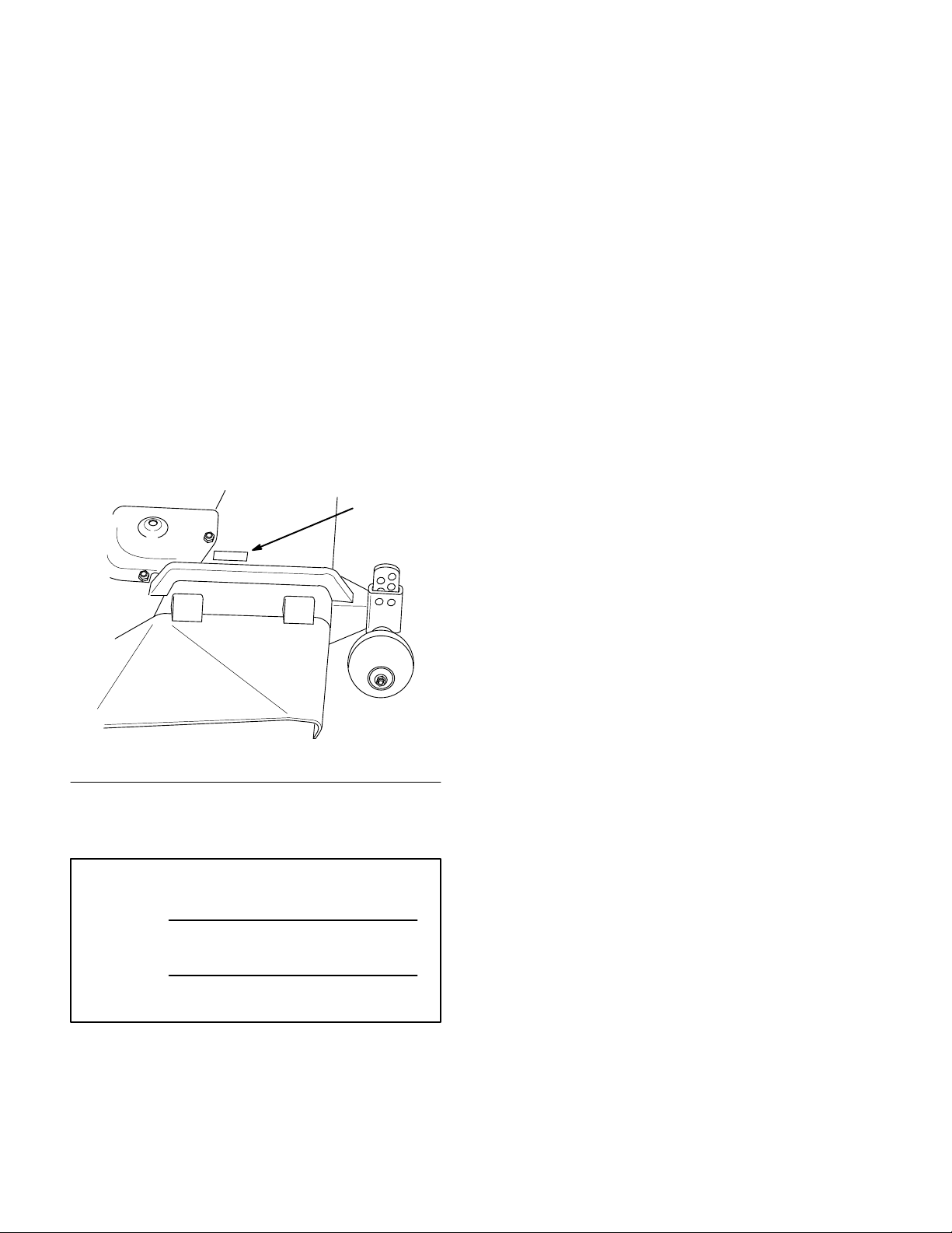
plate located in a unique place on the product as
shown below
.
1
The warning system in this manual identifies
potential hazards and has special safety messages that
help you and others avoid personal injury, even death.
DANGER, WARNING and CAUTION are signal
words used to identify the level of hazard. However,
regardless of the hazard, be extremely careful.
DANGER signals an extreme hazard that will cause
serious injury or death if the recommended
precautions are not followed.
WARNING signals a hazard that may cause serious
injury or death if the recommended precautions are
not followed.
CAUTION signals a hazard that may cause minor or
moderate injury if the recommended precautions are
not followed.
Two other words are also used to highlight
information. “Important” calls attention to special
mechanical information and “Note” emphasizes
general information worthy of special attention.
m–2371
1. Model
For your convenience, write the product model and
serial numbers in the space below.
Model No:
Serial No.
and Serial Number Plate
The left and right side of the machine is determined
by sitting on the seat in the normal operator’s
position.
Printed in USA
Page 3

Contents
Page
Safety and Instruction Decals 2.
Installation 3
Loose Parts 3
Mower Preparation 4
Tractor Preparation 6
Installing the Mower 8
Transport Height Adjustment 9
Side-to-Side Mower Leveling 10
Front-to-Rear Blade Slope 11
Removing the Mower 12
Operation 13
Side Discharge 13
Operating the Power Take Off (PTO) 13
. . . . . . . . . . . . . . . . . . . . . . . . . . . . .
. . . . . . . . . . . . . . . . . . . . . . . . .
. . . . . . . . . . . . . . . . . . .
. . . . . . . . . . . . . . . . . . .
. . . . . . . . . . . . . . . . . . . . . . . . . . . . . .
. . . . . . . . . . . . . . . . . . . . . .
. . . . . . . . . . . . .
. . . . . . . . . . . . . . . . .
. . . . . . . . . . .
. . . . . . . . . .
. . . . . . . . . . . . .
. . . . . . . . . . . . . . . . .
. . . .
Page
Attachment Lift Lever 14
Attachment Power Lift 14
Adjusting Dial-A-Height 15
Adjusting Gage Wheels15. . . . . . . . . . . . . . .
Tips for Mowing Grass 16
Maintenance 17
Service Interval Chart 17
Cutting Blade18. . . . . . . . . . . . . . . . . . . . . . .
Greasing and Lubrication 20
Blade Drive Belt 20
Power Take Off (PTO) Belt 21
Washing Underside of Mower 22
Storage 23
Troubleshooting 24
. . . . . . . . . . . . . . . . . . . . . . . . . . . .
. . . . . . . . . . . . . . . . . . . . . . . . . . . .
. . . . . . . . . . . . . . . . . . . . . . . . .
. . . . . . . . . . . . . . . .
. . . . . . . . . . . . . . . .
. . . . . . . . . . . . . .
. . . . . . . . . . . . . . .
. . . . . . . . . . . . . . . .
. . . . . . . . . . . . . .
. . . . . . . . . . . . . . . . . . . . .
. . . . . . . . . . . .
. . . . . . . . . .
1
Page 4
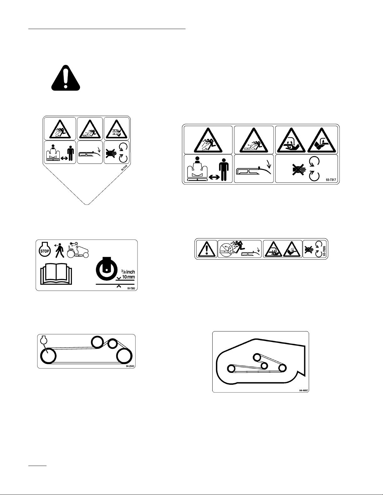
Safety
Safety
ON GRASS DEFLECT
NEXT T
and Instruction Decals
Safety decals and instructions are easily visible to the operator and are located near
any area of potential danger. Replace any decal that is damaged or lost.
OR
(Part No. 93–7317)
O GAGE WHEELS
(Part No. 93–7282)
ON MOWER LEFT AND
DISCHARGE CHUTE
(Part No. 93–7316)
UNDER GRASS DEFLECT
(Part No. 93–7009)
OR
ON MOWER LEFT SIDE
(Part No. 94–2543)
2
ON MOWER REAR CENTER
(Part No. 94–4937)
Page 5

Installation
Loose
Parts
Note: Use the chart below to identify parts used for assembly.
DESCRIPTION QTY. USE
Gage wheel
Shoulder bolt
Lock nut 3/8” (with patch on threads)
Rear link
Washer
Cotter pin
Adjustable links
Washer 3/8” (10 mm)
Cotter pin 1” (26 mm)
Grass deflector
Spring
Bolt 3/8– 24 x 3-1/2” (89 mm)
Lock nut 3/8”
2
2
2
1
2
2
2
2
2
1
2
2
2
Install gage wheels
Install rear link
Install front mount to mower
Install grass deflector
Up stop
Electric clutch
Hairpin cotter–large
Washer 3/4” (19 mm)
Link pin
Hairpin cotter–small
Washer 1/2” (13 mm)
Operator’
s Manual
1
1
2
2
1
3
3
1
Install on tractor
Install mower to tractor
Read before operating
3
Page 6
Installation
Mower
Preparation
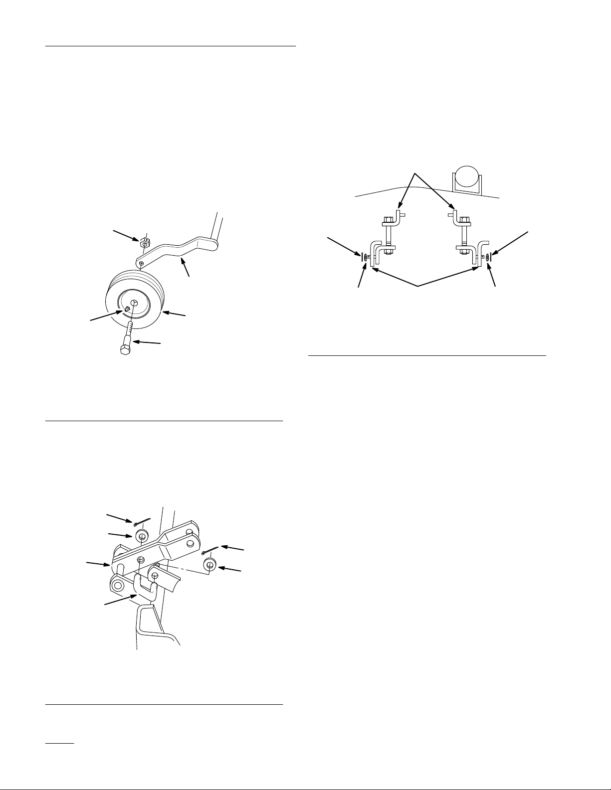
1. Attach gage wheels to the outside of arms on
rear carrier assembly. Grease fitting on wheel
must face out (Fig. 1).
2. Secure with shoulder bolt and 3/8” lock nut,
with internal locking patch on threads (Fig. 1).
Note:
3
1. Carrier
2. Wheel
3.
Grease fitting out
Grease wheels.
5
arm
4
Figure 1
1
2
4.
Shoulder bolt
5.
Lock nut 3/8” (with patch)
m–2389
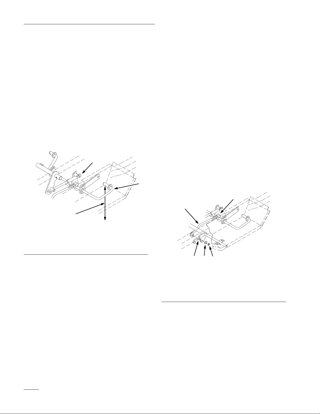
5. Rotate adjustable links so bolt heads are up and
place between brackets, as shown, on front of the
mower (Fig. 3).
6. Secure to brackets with 1/2” washers and 1”
(26 mm) cotter pins (Fig. 3).
1
4
m–3285
3
1. Adjustable
2. Bracket
3
link
2
Figure 3
asher 1/2”
3. W
4.
Cotter pin 1” (26 mm)
4
3. Install rear link between mower bracket and
carrier lift arm (Fig. 2).
4. Secure with 1/2” washers and 1” (26 mm) cotter
pins (Fig. 2).
4
3
4
1. Rear
2.
Carrier lift arm
2
link
1
Figure 2
3. W
asher 1/2”
4.
Cotter pin 1” (26 mm)
3
m–3388
4
Page 7
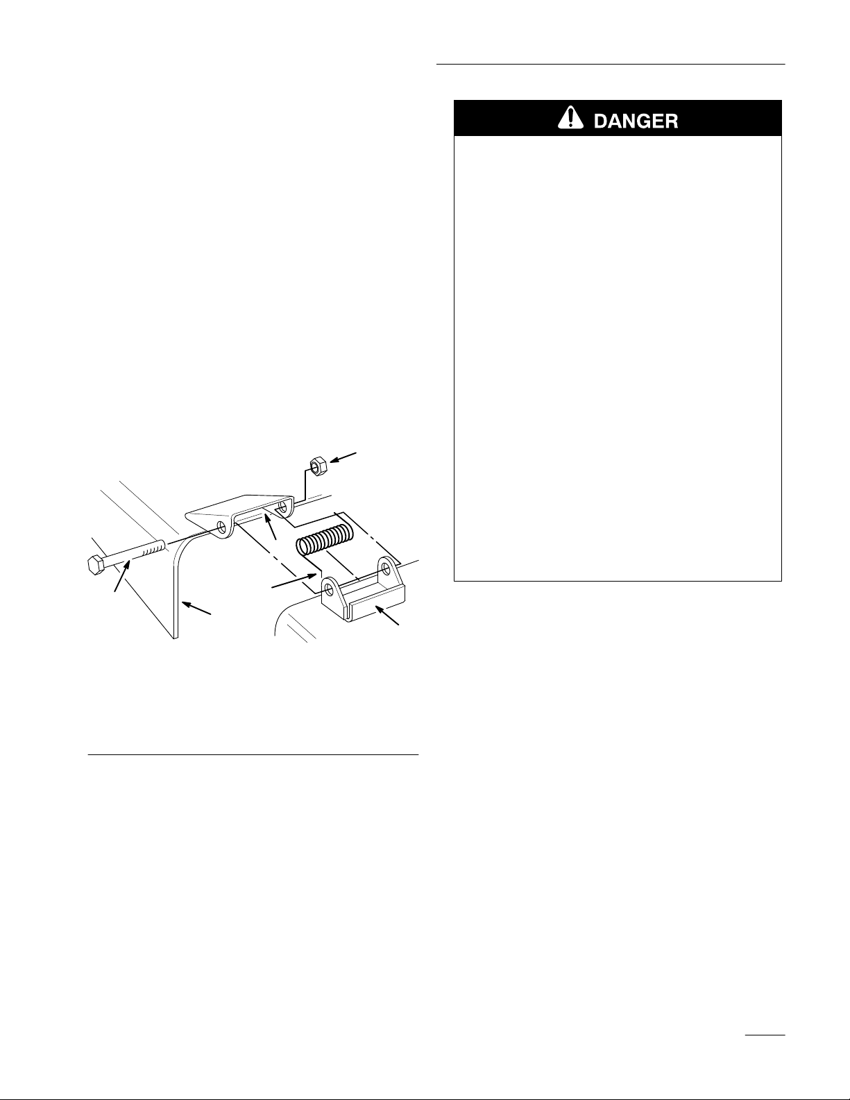
7. Place springs into brackets on mower with
hooked ends over raised back (Fig. 4).
Installation
8. Align grass deflector with holes in brackets and
spring straight ends in space under hinge and
above deflector (Fig. 4).
9. Secure deflector to bracket with 3/8–3-1/2”
(89 mm) bolts through grass deflector, springs
and brackets. Secure with 3/8” lock nuts (Fig. 4).
10. Lift grass deflector and check that it is spring
loaded and pivots freely to the full down
position.
IMPORTANT: Grass deflector must be
spring loaded in the down position. Lift
deflector up to test that it snaps to the full
down position.
6
3
POTENTIAL
HAZARD
• Without the grass deflector, discharge
cover, or complete grass catcher assembly
mounted in place, you and others are
exposed to blade contact and thrown
debris.
WHAT CAN HAPPEN
• Contact with rotating mower blade(s) and
thrown debris will cause injury or death.
HOW TO AV
•
NEVER r
OID THE HAZARD
emove the grass deflector from
the mower because the grass deflector
routes material down toward the turf. If the
grass deflector is ever damaged, replace it
immediately.
• Never put your hands or feet under the
mower.
• Never try to clear discharge area or mower
blades unless you move the power take off
(PTO) to “OFF” and rotate the ignition key
to “OFF.” Also remove the key and pull the
wire off the spark plug(s).
5
1. Bracket
2. Spring
3.
space for spring
hook end
2
4
Figure 4
4.
Grass deflector
5.
Bolt 3/8–3-1/2” (89 mm)
6.
Lock nut 3/8”
1
m–1783
5
Page 8
Installation
Tractor
Preparation
1. Park the machine on a level surface and lower
attachment lift to the full “DOWN” position.
Refer to Operation: Attachment Lift page 14.
Note: Turn Dial-A-Height control to allow
lift to go to full “MOUNTING”
position.
2. Adjust air pressure in tires to recommended
pressure.
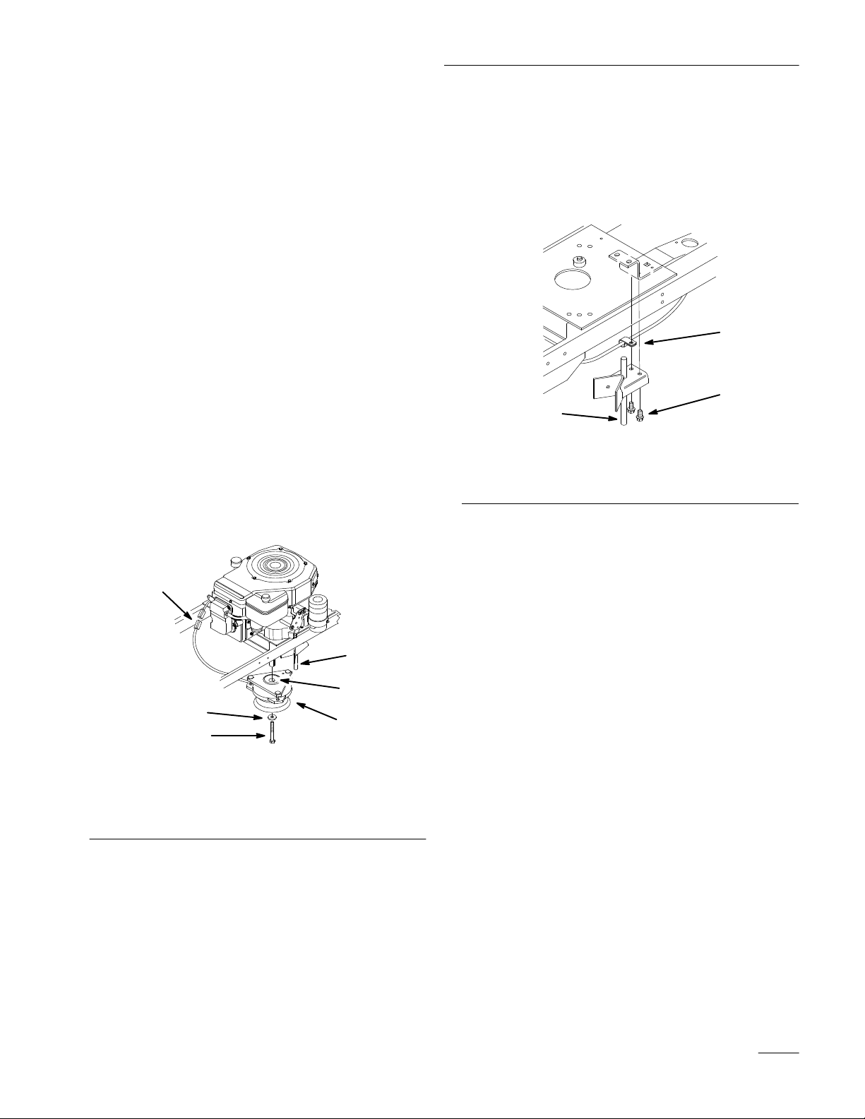
3. Adjust transport height nut until bottom of rear
lift arms are approximately 7-1/4” (188 mm)
from the level surface (Fig. 5).
1
4. Raise attachment lift to the full “UP” position.
Refer to Operation: Attachment Lift page 14.
5. Remove E-ring, washer and lift link from front
lift arm (Fig. 6).
6. Hold front lift arm up until stop contacts frame
(Fig. 6).
7. Push back hard on lift rod, to raise linkage, and
check location of lift rod compared to mounting
hole location.
8. Adjust length of lift rod, by turning in\out of
trunnion, so end just slides into mounting hole in
front lift arm (Fig. 6).
9. Slide lift rod into hole and secure with
previously removed washer and E-ring (Fig. 6).
10. Check that stop is 0”–1/8” (0–3 mm) away frame
when fully assembled and lift in the full “UP”
2
position.
1. Transport
2.
Rear lift arms
height nut
3
Figure 5
3.
7-1/4” (188 mm)
1. E-ring
2. Washer
3. Stop
on lift arm
5
4
2
1
Figure 6
4.
Lift link
5. Trunnion
m–3398
3
6
Page 9
Installation
11. Unplug clutch wire terminal from tractor wire
harness. Remove center retaining bolt and
washer then slide double pulley clutch off shaft
(Fig. 7).
Note: Center bolt is installed with thread
locking compound, impact wrench
may be required to remove.
Note: Save hardware for use when installing
single pulley clutch.
12. Position clutch so wire points toward right front
of tractor and point of triangle is in captured
up-stop. Align key in clutch with keyway and
slide single pulley clutch onto shaft (Fig. 7).
Secure with thread locking compound on threads
of previously removed hardware.
13. Torque bolt to 55 ft-lbs. (75 N
.
m)
14. Route clutch wire around engine mounting plate
and plug into terminal of tractor wire harness
(Fig. 7).
15. Remove bolts securing existing up-stop to
tractor frame (Fig. 8).
16. Place J-clip, holding drain hose, against frame
and mount new, long, up-stop to frame with
previously removed hardware (Fig. 8).
2
3
1. Up-stop
2. J-clip
(long)
1
Figure 8
Existing bolts
3.
m–3390
1. Clutch
2. Terminal
3. Bolt
2
6
5
4
1
3
m-2416
Figure 7
4. Washer
5. Key
6. Up-stop
7
Page 10

Installation
Installing
the Mower
1. Park the machine on a level surface, disengage
the power take off (PTO), set the parking brake,
and turn the ignition key to “OFF” to stop the
engine. Remove the key.
2. Turn the front wheels straight ahead and raise
attachment lift lever all the way to the latched
position; refer to tractor Operator’
s Manual.
3. Slide the mower under tractor from right side,
turning front wheels as necessary. Align rear
mounting bushings with ends of lift arms.
4. Turn Dial-a-Height knob counterclockwise, all
the way, and lower attachment lift lever to the
mounting position; refer to Operation page 15.
5. Install front adjustable links to front lift arms
with 1/2” washer and small hairpin cotter
(Fig. 9). Belt straddles left hand link.
9. Pull on drive belt and rotate onto engine pulley
to install (Fig. 10).
Note: Make sure belt is properly located in
engine and deck pulleys and around
idler pulley.
10. Adjust belt guide so distance between belt and
guide is 1/8” (4 mm) (Fig. 10).
1
4
3
Figure 10
2
m–2418
6. Place rear guide bushings, first left side then
right, onto lift arms then slide deck left into
position (Fig. 9).
7. Secure deck to rear lift arms with 3/4” washers
and large hairpin cotters (Fig. 9).
8. Attach rear link to attachment lift with link pin,
1/2” washer and small hairpin cotter (Fig. 9).
6
5
7
2
3
1. Lift
arm
2. W
asher 3/4”
3.
Hair pin cotter–large
4.
Attachment lift
Figure 9
4
1
5. W
asher 1/2”
6.
Hair pin cotter–small
7.
Link pin
6
5
m–2373
T
op V
iew
1. Idler
2.
pulley
Drive belt
3.
Engine pulley
4.
1/8” (4 mm)
11. Check mower level; refer to Side-to-Side Mower
Leveling page 10, and Front-to-Rear Blade
Leveling page 11.
12. Raise attachment lift lever all the way to the
latched position and adjust mower transport
height adjustment; refer to page 9.
8
Page 11

Installation
Transport
Height Adjustment
Transport height should be properly adjusted after
Tractor Preparation, page 6; however if the rear
brackets contact the footrest or up–stop contacts the
top of mower in the raised position, adjustment is
required.
1. Adjust by turning transport height nut, (Fig. 11)
on lift mechanism, clockwise to raise or
counterclockwise to lower mower.
2. Adjust nut until there is 1/4” (6 mm) clearance
between rear brackets and footrest and up–stop
and mower.
1
1. Nut
Figure 1
m–1223
1
9
Page 12

Installation
Side-to-Side
Mower Leveling
The mower blades must be level from side to side.
Check the side-to-side level any time you install the
mower or when you see an uneven cut on your lawn.
Before you level the mower, set the air pressure in the
front and rear tires to 12 psi (.85 kPa).
3” to 4” (76-102 mm) Height-of-Cut Range
When the mower height-of-cut is set to the 3” to 4”
(76-102 mm) range the mower is suspended from the
tractor.
1. Park the machine on a level surface, disengage
the power take off (PTO), set the parking brake,
and turn the ignition key to “OFF” to stop the
engine. Remove the key.
2. Raise attachment lift lever all the way to the
latched position.
3. Carefully rotate blade(s) side to side (Fig. 12).
Measure between the outside cutting edges and
the flat surface (Fig. 12). If both measurements
are not within 3/16” (5 mm), an adjustment is
required; refer to steps 4 and 6.
4. Loosen adjustment bolt on one side and rotate
hanger bracket to raise or lower mower (Fig. 13).
5. After adjusting, tighten bolt and check
side-to-side level.
IMPORTANT: If hanger is rotated to the end
of adjustment on one side and mower is not
level, adjust the opposite side.
1
2
m–1224
Figure 13
1. Bolt 2. Hanger
bracket
6. Now check the front-to-rear blade slope; refer to
Front-to-Rear Blade Slope, page 11.
2
3
1. Blades
2.
side to side
Outside cutting edges
Front
1
Figure 12
3.
2
Measure here
1-1/2”to 3” (38-76 mm) Height-of-Cut
Range
When the mower height-of-cut is set to the 1-1/2” to
3” (38-76 mm) range the rear gage wheels contact the
ground. There is no side-to-side adjustment for this
height range. The gage wheels provide this
adjustment. See Front-to-Rear Blade Slope.
3
m–1078
10
Page 13

Installation
Front-to-Rear
Blade Slope
Check the front-to-rear blade slope any time you
install the mower. Before checking the slope, set air
pressure in the front and rear tires to 12 psi (.85 kPa).
If the front blade tip is not 0–3/8” (0–9.5 mm) lower
than the rear blade tip, adjust the blade slope using
the following instructions:
1. Park the machine on a level surface, disengage
the power take off (PTO), set the parking brake,
and turn the ignition key to “OFF” to stop the
engine. Remove the key.
2. Check and adjust side-to-side blade level if you
have not checked the setting; refer to
Side-to-Side Mower Leveling, page 10.
3. Adjust the Dial-A-Height knob so the
height-of-cut is in the middle of the range and
lower attachment lift.
4. Carefully rotate blades so they are facing front
and rear (Fig. 14).
5. Measure between the tip of the front blade
(Fig. 14). and the tip of the rear blade to the flat
surface. If the front blade tip is not 0–3/8”
(0–9.5 mm) lower than the rear blade tip adjust
front adjustment links.
2
Front
m–1078
6. To adjust front-to rear blade level loosen jam nut
on front adjustable links. (Fig. 15).
7. Rotate the bolt on front adjustable links to
change front-to rear blade level (Fig. 15).
Note: To raise the front of the mower,
shorten the adjustable links by turning
bolt clockwise.
Note: Adjust front adjustable links equally to
maintain side-to-side level.
3
1
2
m–3286
Figure 15
1. Adjustable
2.
Jam nut
link
3. Bolt
8. When front-to-rear slope is correct, tighten jam
nuts. Recheck side-to-side mower level; refer to
Side-to-Side Mower Leveling, page 10.
4
1. Blade
2.
front to rear
Measure front blade tip
1
Figure 14
3.
4.
3
4
Measure rear blade tip
Measure here
11
Page 14

Installation
Removing
the Mower
1. Park the machine on a level surface, disengage
the power take off (PTO), set the parking brake,
and turn the ignition key to “OFF” to stop the
engine. Remove the key.
2. Raise attachment lift, turn Dial-a-Height knob
counterclockwise, all the way, and lower the
attachment lift lever to the mounting position;
refer to tractor Operator’
s Manual.
3. Remove mower drive belt from engine pulley.
4. Remove hairpin cotter, washer and link pin from
rear link and remove from attachment lift
(Fig. 16).
5. Remove hairpin cotter and washer from front
adjustable link(s) and remove from front lift arm
(Fig. 16).
6. Remove hairpin cotters and washers from rear
lift arms (Fig. 16).
7. Slide deck right, off rear lift arms (Fig. 16).
3
2
1
6
7
1. Link
pin
2. W
asher 1/2”
3.
Hair pin cotter–small
4.
Attachment lift
Figure 16
4
1
5.
Lift arm
6. W
asher 3/4”
7.
Hair pin cotter–large
3
2
m–2373
8. Raise attachment lift all the way to the latched
position. Turn the front wheels, as necessary, and
slide mower out to the the right side.
Note: Save all hardware, washers and hairpin
cotters for use when installing deck.
12
Page 15

Operation
Side
Discharge
POTENTIAL
HAZARD
• Without the grass deflector, discharge
cover, or complete grass catcher assembly
mounted in place, you and others are
exposed to blade contact and thrown
debris.
WHAT CAN HAPPEN
• Contact with rotating mower blade(s) and
thrown debris will cause injury or death.
HOW TO AV
•
NEVER r
the mower because the grass deflector
routes material down toward the turf. If the
grass deflector is ever damaged, replace it
immediately.
OID THE HAZARD
emove the grass deflector from
• Never put your hands or feet under the
mower.
• Never try to clear discharge area or mower
blades unless you move the power take off
(PTO) to “OFF” and rotate the ignition key
to “OFF.” Also remove the key and pull the
wire off the spark plug(s).
Operating
Power T
The power take off (PT
power to the electric clutch.
While the ignition key is in the “RUN” or “LIGHTS”
positions and the power take off (PTO) is engaged
“ON“, the PTO light, in the Indicator Module, will be
“ON“. When this light is “ON” it is a reminder; the
starter will not crank and to turn the PTO off before
getting off.
the
ake Off (PT
O) engages and disengages
O)
Engaging the Power Take Off (PTO)
1. Depress the brake and/or clutch pedal(s) to stop
the machine.
2. Pull the power take off (PTO) to “ON” (Fig. 17).
1
2
1. The mower has a hinged grass deflector that
disperses clippings to the side and down toward
the turf.
m–1206
Figure 17
1. Off-Disengaged 2. On-Engaged
Disengaging the Power Take Off (PTO)
1. Depress the brake and/or clutch pedal(s) to stop
the machine.
2. Push the power take off (PTO) to “OFF”
(Fig.17).
13
Page 16

Operation
Attachment
Lift Lever
The attachment lift lever (Fig. 18) is used to raise and
lower various attachments.
Raising Attachments
1. Depress the brake pedal to stop the machine.
2. Pull attachment lift lever rearward until latch
locks. In this position the lift will hold the
attachment in the up, or raised position.
Lowering Attachments
1. Depress the brake and/or clutch pedal(s) to stop
the machine.
2. Pull attachment lift lever rearward, to release lift
pressure, and push the button on top to release
the latch. Move lift lever forward to lower
attachment.
Attachment
Power Lift
The attachment power lift (optional on some models)
(Fig. 19) is used to raise and lower attachments.
Raising Attachments
1. Turn key to the “ON” or “RUN” position
(Fig. 19).
2. Push the lift switch in the “UP” direction to raise
the attachment lift (Fig. 19). This will lift and
hold the attachment in the up, or raised position.
Lowering Attachments
1. Turn key to the “ON” or “RUN” position
(Fig. 19).
2. Push the lift switch in the “DOWN” direction to
lower the attachment lift (Fig. 19). This will
lower the attachment lift.
2
1
1. Lift
lever
2. Button
3. Dial-A-Height
Figure 18
4. Indicator
5. High
6.
3
5
6
Mounting position
4
m–1205
1. Key
2. Lift
2
3
switch UP
Figure 19
3.
1
m–2266
Lift switch DOWN
14
Page 17

Operation
Adjusting
Dial-A-Height
The Dial-A-Height control (Fig. 18) is used to limit
the downward travel of the attachment. The
Dial-A-Height knob is rotated to change the location
of this stop, up or down.
1. Raise the attachment lift lever: Refer to Raising
Attachments. In the raised, position the
Dial-A-Height knob (Fig. 18) can be rotated to
change the stop location. Turn clockwise to raise
and counterclockwise to lower the height of the
attachment.
2. The Dial-A-Height indicator (Fig. 18) will show
the change, high to low, in attachment lift height
as adjustment is made.
Adjusting
Gage Wheels
The gage wheels (on certain models) must be
adjusted in the proper hole location for each
height-of-cut position.
1. After adjusting height-of-cut. raise the
attachment lift lever: Refer to Raising
Attachments.
2. Remove hairpin cotter and pin to change hole
location (Fig. 20).
3. Select a hole position so the gage wheel is 3/8”
(9.5 mm) off the ground for the height-of-cut to
be used (Fig. 20).
4. Insert pin and secure with hairpin cotter.
5. Repeat adjustment on other gage wheels.
3
1. Wheel
2. Pin
2
1
m–1233
Figure 20
3. Hair
pin Cotter
15
Page 18

Operation
Tips
for Mowing Grass
Fast Throttle Setting
For best mowing and maximum air circulation,
operate the engine at “FAST.” Air is required to
thoroughly cut grass clippings, so do not set the
height-of-cut so low, as to totally surround the mower
by uncut grass. Always try to have one side of the
mower free from uncut grass, which allows air to be
drawn into the mower.
Cutting a Lawn for the First Time
Cut grass slightly longer than normal to ensure the
cutting height of the mower does not scalp any
uneven ground. However, the cutting height used in
the past is generally the best one to use. When cutting
grass longer than six inches tall, you may want to cut
the lawn twice to assure an acceptable quality-of-cut.
Cut 1/3 of the Grass Blade
It is best to cut only about 1/3 of the grass blade.
Cutting more than that is not recommended, unless
grass is sparse or it is late fall when grass grows more
slowly.
Mowing Direction
Ground Speed
To improve cut quality, use slower ground speed.
Avoid Cutting Too Low
If the cutting width of the mower is wider than the
mower you previously used, raise the cutting height
to ensure uneven turf is not cut too short.
Long Grass
If the grass is ever allowed to grow slightly longer
than normal, or if it contains a high degree of
moisture, raise the cutting height higher than usual
and cut the grass at this setting. Then cut the grass
again using the lower, normal setting.
When Stopping
If the machine’s forward motion must be stopped
while mowing, a clump of grass clippings may drop
onto your lawn. To avoid this:
1. With the blade(s) “ENGAGED,” move onto a
previously cut area.
2. To disperse the clippings evenly, raise the mower
slightly with the mower lift while driving
forward with the blade(s) “ENGAGED.”
Alternate mowing direction to keep the grass standing
straight. This also helps disperse clippings which
enhances decomposition and fertilization.
Mow at Correct Intervals
Normally, mow every 4 days. But remember, grass
grows at different rates at different times. So to
maintain the same cutting height, which is a good
practice, mow more often in early spring. As the
grass growth rate slows in mid summer, mow less
frequently. If you cannot mow for an extended period,
first mow at a high cutting height; then mow again 2
days later at a lower height setting.
16
Keep the Underside of the Mower Clean
Clean clippings and dirt from the underside of the
mower after each use. If grass and dirt build up inside
the mower, cutting quality will eventually become
unsatisfactory.
Blade Maintenance
Maintain a sharp blade throughout the cutting season
because a sharp blade cuts cleanly without tearing or
shredding the grass blades. Tearing and shredding
turns grass brown at the edges, which slows growth
and increases the chance of disease. Every 30 days,
check the cutter blade(s) for sharpness and file down
any nicks.
Page 19

Maintenance
Service
Service
Cutter Blade—check
Grease–Mower spindles, wheels
Belts—check for wear/cracks
Mower Housing—clean
Chipped Surfaces—paint
Interval Chart
Operation
POTENTIAL HAZARD
• If you leave the key in the ignition switch, someone could start the engine.
WHAT CAN HAPPEN
• Accidental starting of the engine could seriously injure you or other bystanders.
HOW TO AV
OID THE HAZARD
• Remove the key from the ignition switch and pull the wire off the spark plug before
you do any maintenance. Also push the wire aside so it does not accidentally contact
the spark plug.
Each
Use5Hours25Hours
X X X
X X
X X X
Storage
Service
X
X
Spring
Service
Notes
17
Page 20

Maintenance
Cutting
Blade
To assure a superior quality of cut, keep the blade(s)
sharp. For convenient sharpening and replacement,
you may want to have an extra blade(s).
POTENTIAL HAZARD
• A blade that is worn or damaged could
break apart and pieces could be thrown at
bystanders or at you as you use the mower.
WHAT CAN HAPPEN
• Pieces of blade that may be thrown could
seriously injure or kill you or bystanders.
HOW TO AV
OID THE HAZARD
• Periodically inspect the blade for wear and
damage. Immediately install a new blade if
it is worn or damaged.
Inspecting the Blade(s)
1. Remove the mower; refer to Removing the
Mower, page 12.
2. Inspect the cutting edges (Fig. 21). If the edges
are not sharp or have nicks, remove the blade(s)
and sharpen them; refer to Sharpening the
Blade(s), page 19.
1
3
m–151
1. Cutting
2.
Curved area
edge
Figure 21
3. W
2
ear/slot forming
Removing the Blade
1. Remove the mower; refer to Removing the
Mower, page 12.
2. Carefully tip the mower over.
3. Remove the bolt, blade stiffener and blade
(Fig. 22). A block of wood may be wedged
between the blade and the mower to lock the
blade when you are removing the bolt.
4. Inspect all parts. If a defect or damage is noticed,
install new parts.
3. Inspect the blade(s), especially the curved area
(Fig. 21). If you notice any damage, wear, or a
slot forming in this area (Fig. 21), immediately
install a new blade.
18
1. Blade
2. Blade
stif
4
fener
Figure 22
3. Bolt
4. Spindle
1
2
3
m-2376
Page 21

Maintenance
Sharpening the Blade(s)
1. Use a file to sharpen the cutting edge at both
ends of the blade (Fig. 23). Maintain the original
angle. The blade retains its balance if the same
amount of material is removed from both cutting
edges.
1
Figure 23
1. Sharpen
2. Check the balance of the blade by putting it on a
blade balancer (Fig. 24). If the blade stays in a
horizontal position, the blade is balanced and can
be used. If the blade is not balanced, file some
metal off the back side of the blade. Repeat this
procedure until the blade is balanced.
at original angle
Installing the Blade(s)
1. Install the blade, blade stiffener and bolt
(Fig. 25).
IMPORTANT: The curved part of the blade
must be pointing up, toward the inside of the
mower, to assure proper cutting.
2. Tighten the bolt to 80-100 ft–lb (109-136 Nm).
1. Blade
2. Blade
stif
4
fener
Figure 25
3. Bolt
4. Spindle
1
2
3
m-2376
2
1
Figure 24
1. Blade 2. Balancer
19
Page 22

Maintenance
Greasing
and Lubrication
Service Interval/Specification
Grease the mower after every 25 operating hours or
once a year, whichever occurs first. Grease more
frequently when operating conditions are extremely
dusty or sandy.
Grease Type: General-purpose grease.
How to Grease
1. Disengage the power take off (PTO), set the
parking brake, and turn the ignition key to
“OFF” to stop the engine. Remove the key
2. Clean the grease fittings with a rag. Make sure to
scrape any paint off the end of the fitting(s).
3. Connect a grease gun to the fitting. Pump grease
into the fittings.
Blade
Drive Belt
Removing the Blade Drive Belt
1. Remove the mower; refer to Removing the
Mower, page 12.
2. Remove pulley cover mounting screws and
pulley covers from both blade pulleys.
3. Loosen idler spring and remove the belt from the
pulleys (Fig. 28).
Installing the Blade Drive Belt
1. Install the new belt around the blade pulleys and
the idler pulley (Fig. 27).
4. Wipe up any excess grease.
Where to Add Grease
1. Lubricate the blade spindles, idler pulley arm
and gage wheel bearings (Fig. 26).
Figure 26
m–2415
Figure 27
m–2429
20
Page 23

Maintenance
2. Adjust idler spring tension until length between
hooks is 5-1/2” (140 mm) (Fig. 28).
2
1
m–2417
Figure 28
T
op V
iew
1. Idler
spring
2.
5-1/2” (140 mm)
3. Install left and right pulley covers with
previously removed mounting screws.
4. Install the mower; refer to Installing the Mower,
page 8.
Power Take Off (PT
O) Belt
Removing PTO Belt
1. Remove the mower; refer to Removing the
Mower, page 12.
2. Remove left pulley cover mounting screws and
pulley cover. Remove PTO belt (Fig. 29).
Installing the PTO Belt
1. Install the new belt around the blade pulley and
the idler pulleys.
2. Install left pulley cover with previously removed
mounting screws (Fig. 29).
3. Install the mower; refer to Installing the Mower,
page 8.
4. Adjust belt guide so distance between belt and
guide is 1/8” (4 mm) (Fig. 29).
1. Left
2. PT
pully cover
O belt
Figure 29
3.
2
1/8” (4 mm)
1
3
m–2418
21
Page 24

Maintenance
Washing
Underside of Mower
After each use wash the underside of the mower to
prevent grass build-up for improved mulch action and
clipping dispersal.
1. Park the machine on a hard level surface,
disengage the power take off (PTO) and turn the
ignition key to “OFF” to stop the engine.
2. Attach hose coupling to the end of the left
mower washout fitting, turn water on high
(Fig. 30).
Note: Spread petroleum jelly on washout
fitting o-ring to make coupling slide on
easier and protect o-ring.
3. Lower the mower to the lowest height-of-cut.
4. Sit on the seat and start the engine. Engage
power take off (PTO) and let mower run for one
to three minutes.
5. Disengage the blade, power take off (PTO) and
turn the ignition key to “OFF” to stop the
engine. Wait for all moving parts to stop.
4
2
1
3
Figure 30
1. Washout
2.
Coupling (not supplied)
POTENTIAL
fitting left
HAZARD
3. Hose
4. W
ashout fitting right
• A broken or missing washout fitting could
expose you and others to thrown objects or
blade contact.
WHAT CAN HAPPEN
• Contact with thrown debris or blade
contact will cause injury or death.
m–3473
6. Repeat washing with hose attached to right
washout fitting.
7. Turn the water off, remove hose coupling from
the washout fitting.
Note: If the mower is not clean after one
washing, soak and let stand for 30
minutes. Then repeat process again.
8. Run mower again for one to three minutes to
remove excess water
.
HOW TO AV
OID THE HAZARD
• Replace broken or missing washout fitting
immediately, before using mower again.
• Plug any hole(s) in mower with bolts and
locknuts.
• Never put your hands or feet under the
mower or through openings in the mower.
22
Page 25

Storage
1. Clean dirt and chaff from the outside of the
engine’s cylinder head fins and blower housing.
Also remove grass clippings, dirt, and grime
from the external parts of the entire machine,
especially the engine, shrouding, and the top of
the mower.
IMPORTANT: You can wash the machine
with mild detergent and water. Do not
pressure wash the machine. A
use of water, especially near the control panel,
lights, engine, and the battery.
2. Wash the underside of the mower; refer to
Washing Underside of Mower, page 22.
3. Check the condition of the blade(s); refer to
Cutting Blade, page 18.
void excessive
Maintenance
4. Check the condition of the blade drive belt.
5. Grease the mower deck; refer to Greasing and
Lubrication, page 20.
6. Check and tighten all bolts, nuts, and screws.
Repair or replace any part that is damaged or
defective.
7. Paint all scratched or bare metal surfaces. Paint
is available from your Authorized Service
Dealer.
8. Store the machine in a clean, dry garage or
storage area. Remove the key from the ignition
switch and keep it in a memorable place. Cover
the machine to protect it and keep it clean.
23
Page 26

Troubleshooting
gg
PROBLEM
Abnormal vibration.
Blade(s) does not rotate.
Uneven cutting height.
POSSIBLE CAUSES
1.
Cutting blade(s) is bent or
unbalanced.
2.
Blade mounting bolt is loose.
3.
Engine mounting bolts are
loose.
4.
Loose engine pulley
pulley
, or blade pulley
5.
Engine pulley is damaged.
1.
Blade drive belt is worn, loose
or broken.
2.
Blade drive belt is off pulley
3. PT
1. T
2.
O belt is worn, loose or
broken.
ire pressure is incorrect.
Mower is not level.
, idler
.
1.
2. T
3. T
4. T
5.
1.
. 2.
3.
1.
2.
CORRECTIVE ACTION
Install new cutting blade(s).
ighten blade mounting bolt.
ighten engine mounting
bolts.
ighten the appropriate
pulley.
Contact Authorized Service
Dealer.
Install new blade drive belt.
Install blade drive belt and
check idler pulley and belt
guides for correct position.
Install new PT
Set tire pressure.
Level mower from
side-to-side and front-to-rear.
O belt.
3.
Underside of mower is dirty
. 3.
Clean the underside of the
mower.
24
Page 27

Page 28

 Loading...