

Page 1

FormNo.3375-781RevA
TITANZX4820orZX5420
Zero-Turn-RadiusRidingMower
ModelNo.74920—SerialNo.313000001andUp
ModelNo.74924—SerialNo.313000001andUp
Registeratwww.T oro.com.
OriginalInstructions(EN)
*3375-781*A
Page 2
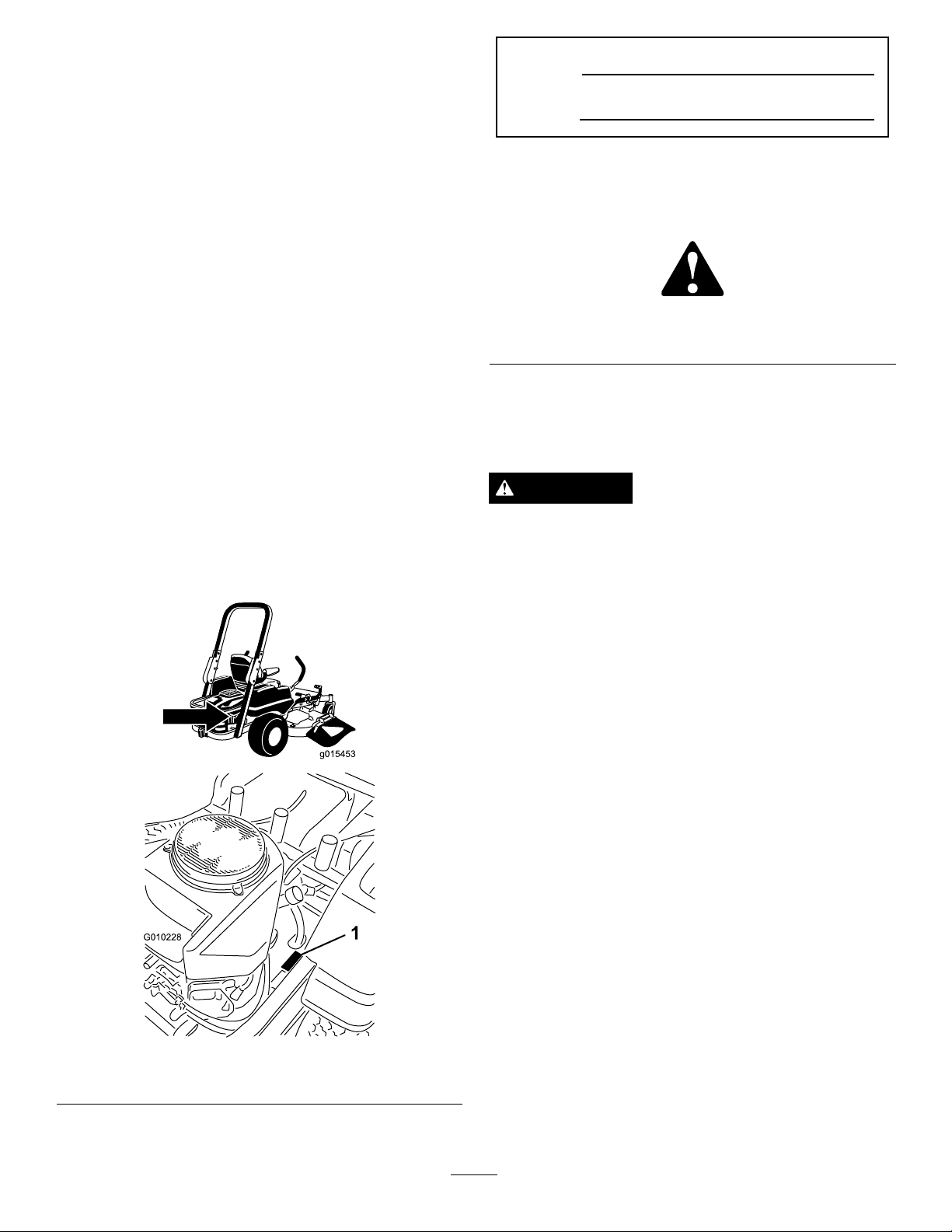
Thismachineisaride-on,rotary-bladelawnmowerintended
G010228
1
tobeusedbyhomeownersinresidentialapplications.Itis
primarilydesignedforcuttinggrassonwell-maintainedlawns.
Itisnotdesignedforcuttingbrush,mowinggrassandother
growthalongsidehighways,orforagriculturaluses.
ModelNo.
SerialNo.
ThisproductcomplieswithallrelevantEuropeandirectives,
fordetailspleaseseetheseparateproductspecicDeclaration
ofConformity(DOC)sheet.
Introduction
Readthisinformationcarefullytolearnhowtooperateand
maintainyourproductproperlyandtoavoidinjuryand
productdamage.Youareresponsibleforoperatingthe
productproperlyandsafely .
YoumaycontactTorodirectlyatwww .Toro.comforproduct
andaccessoryinformation,helpndingadealer,ortoregister
yourproduct.
Wheneveryouneedservice,genuineToroparts,oradditional
information,contactanAuthorizedServiceDealerorToro
CustomerServiceandhavethemodelandserialnumbersof
yourproductready .Figure1identiesthelocationofthe
modelandserialnumbersontheproduct.Writethenumbers
inthespaceprovided.
Thismanualidentiespotentialhazardsandhassafety
messagesidentiedbythesafetyalertsymbol(Figure2),
whichsignalsahazardthatmaycauseseriousinjuryordeath
ifyoudonotfollowtherecommendedprecautions.
Figure2
1.Safetyalertsymbol
Thismanualuses2otherwordstohighlightinformation.
Importantcallsattentiontospecialmechanicalinformation
andNoteemphasizesgeneralinformationworthyofspecial
attention.
WARNING
Removingstandardoriginalequipmentpartsand
accessoriesmayalterthewarranty,traction,and
safetyofthemachine.FailuretouseoriginalT oro
partscouldcauseseriousinjuryordeath.Making
unauthorizedchangestotheengine,fuelorventing
system,mayviolateEPAandCARBregulations.
1.Modelandserialnumberlocation
Replaceallpartsincluding,butnotlimitedto,tires,
belts,blades,andfuelsystemcomponentswith
originalT oroparts.
Formodelswithstatedenginehorsepower,thegross
horsepoweroftheenginewaslaboratoryratedbytheengine
manufacturerinaccordancewithSAEJ1940andratedto
J2723.
Donottamperwiththeenginecontrolsoralterthegovernor
speed;doingsomaycreateanunsafeconditionresultingin
personalinjury.
Figure1
©2012—TheToro®Company
8111LyndaleAvenueSouth
Bloomington,MN55420
Contactusatwww.T oro.com.
2
PrintedintheUSA.
AllRightsReserved
Page 3

Contents
Introduction..................................................................2
Safety...........................................................................4
SafeOperationPracticesforRide-on(riding)
RotaryLawnmowerMachines...............................4
SafeOperatingPractices...........................................4
ToroRidingMowerSafety........................................5
Model74920...........................................................6
Model74924...........................................................6
SlopeIndicator.......................................................7
SafetyandInstructionalDecals.................................8
ProductOverview.........................................................14
Controls...............................................................15
Operation....................................................................16
ThinkSafetyFirst...................................................16
UsingtheRolloverProtectionSystem(ROPS)............16
AddingFuel...........................................................17
CheckingtheEngineOilLevel.................................19
OperatingtheParkingBrake....................................19
OperatingtheThrottle............................................19
OperatingtheChoke...............................................19
OperatingtheIgnitionSwitch..................................19
StartingandStoppingtheEngine..............................20
OperatingtheMowerBladeControlSwitch
(PTO)...............................................................21
TheSafetyInterlockSystem.....................................21
DrivingForwardorBackward..................................22
StoppingtheMachine.............................................23
AdjustingtheHeightofCut.....................................23
AdjustingtheAnti-ScalpRollers...............................25
PositioningtheSeat................................................25
AdjustingtheMotionControlLevers........................25
PushingtheMachinebyHand..................................25
Convertingthe48inchMowertoSide
Discharge..........................................................26
Convertingthe54inchMowertoSide
Discharge..........................................................27
UsingtheSideDischarge.........................................29
OperatingTips......................................................30
Maintenance.................................................................31
RecommendedMaintenanceSchedule(s)......................31
PremaintenanceProcedures........................................33
RaisingtheSeat......................................................33
Lubrication...............................................................33
GreasingtheBearings.............................................33
EngineMaintenance..................................................34
ServicingtheAirCleaner.........................................34
ServicingtheEngineOil..........................................34
ServicingtheSparkPlug..........................................36
CleaningtheCoolingSystem....................................37
FuelSystemMaintenance...........................................38
ReplacingtheFuelFilter..........................................38
ElectricalSystemMaintenance....................................39
ServicingtheBattery...............................................39
ServicingtheFuses.................................................40
DriveSystemMaintenance.........................................41
CheckingtheTirePressure......................................41
HydraulicSystemMaintenance....................................41
CheckingtheHydraulicOilLevel..............................41
ChangingtheHydraulicSystemFilterand
Oil....................................................................41
MowerDeckMaintenance...........................................43
ServicingtheCuttingBlades.....................................43
MowerDeckLeveling.............................................46
InspectingtheBelts................................................47
ReplacingtheMowerBelt........................................47
RemovingtheMower..............................................48
InstallingtheMower...............................................49
ReplacingtheGrassDeector..................................49
Cleaning...................................................................50
WashingtheUndersideoftheMower........................50
WasteDisposal.......................................................51
Storage........................................................................51
CleaningandStorage..............................................51
Troubleshooting...........................................................53
Schematics...................................................................55
3
Page 4

Safety
SafeOperationPractices
forRide-on(riding)Rotary
LawnmowerMachines
ThismachinemeetsorexceedsEuropeanStandardsin
effectatthetimeofproduction.However,improperuseor
maintenancebytheoperatororownercanresultininjury.
Toreducethepotentialforinjury,complywiththesesafety
instructionsandalwayspayattentiontothesafetyalert
symbol,whichmeansCAUTION,WARNING,orDANGER
-“personalsafetyinstruction.”Failuretocomplywiththe
instructionmayresultinpersonalinjuryordeath.
SafeOperatingPractices
ThefollowinginstructionsarefromtheENstandardEN
836:1997.
Thisproductiscapableofamputatinghandsandfeetand
throwingobjects.Alwaysfollowallsafetyinstructionsto
avoidseriousinjuryordeath.
Training
•Readtheinstructionscarefully.Befamiliarwiththe
controlsandtheproperuseoftheequipment.
Preparation
•Whilemowing,alwayswearsubstantialfootwearandlong
trousers.Donotoperatetheequipmentwhenbarefoot
orwearingopensandals.
•Thoroughlyinspecttheareawheretheequipmentisto
beusedandremoveallobjectswhichmaybethrownby
themachine.
•Warning-Fuelishighlyammable.
–Storefuelincontainersspecicallydesignedforthis
purpose.
–Refueloutdoorsonlyanddonotsmokewhile
refueling.
–Addfuelbeforestartingtheengine.Neverremove
thecapofthefueltankoraddfuelwhiletheengineis
runningorwhentheengineishot.
–Iffuelisspilled,donotattempttostarttheengine
butmovethemachineawayfromtheareaofspillage
andavoidcreatinganysourceofignitionuntilfuel
vaporshavedissipated.
–Replaceallfueltanksandcontainercapssecurely.
•Replacefaultysilencers.
•Beforeusing,alwaysvisuallyinspecttoseethattheblades,
bladeboltsandcutterassemblyarenotwornordamaged.
Replacewornordamagedbladesandboltsinsetsto
preservebalance.
•Onmulti-bladedmachines,takecareasrotatingoneblade
cancauseotherbladestorotate.
•Neverallowchildrenorpeopleunfamiliarwiththese
instructionstousethelawnmower.Localregulationscan
restricttheageoftheoperator.
•Nevermowwhilepeople,especiallychildren,orpetsare
nearby.
•Keepinmindthattheoperatororuserisresponsiblefor
accidentsorhazardsoccurringtootherpeopleortheir
property.
•Donotcarrypassengers.
•Alldriversshouldseekandobtainprofessionaland
practicalinstruction.Suchinstructionshouldemphasize:
–theneedforcareandconcentrationwhenworking
withride-onmachines;
–controlofaride-onmachineslidingonaslopewill
notberegainedbytheapplicationofthebrake.The
mainreasonsforlossofcontrolare:
◊insufcientwheelgrip;
◊beingdriventoofast;
◊inadequatebraking;
◊thetypeofmachineisunsuitableforitstask;
◊lackofawarenessoftheeffectofground
conditions,especiallyslopes;
◊incorrecthitchingandloaddistribution.
Operation
•Bealert,slowdownandusecautionwhenmakingturns.
Lookbehindandtothesidebeforechangingdirections.
•Donotoperatetheengineinaconnedspacewhere
dangerouscarbonmonoxidefumescancollect.
•Mowonlyindaylightoringoodarticiallight.
•Beforeattemptingtostarttheengine,disengageallblade
attachmentclutchesandshiftintoneutral.
•Donotuseonslopesofmorethan15degrees.
•Rememberthereisnosuchthingasasafeslope.Travel
ongrassslopesrequiresparticularcare.Toguardagainst
overturning:
–donotstoporstartsuddenlywhengoingupor
downhill;
–uselowspeedsonslopesandduringtightturns;
–stayalertforhumpsandhollowsandotherhidden
hazards;
•Usecarewhenpullingloads.
–Useonlyapproveddrawbarhitchpoints.
–Limitloadstothoseyoucansafelycontrol.
–Donotturnsharply.Usecarewhenreversing.
•Watchoutfortrafcwhencrossingornearroadways.
•Stopthebladesrotatingbeforecrossingsurfacesother
thangrass.
4
Page 5

•Whenusinganyattachments,neverdirectdischargeof
materialtowardbystandersnorallowanyonenearthe
machinewhileinoperation.
•Neveroperatethemachinewithdamagedguardsor
withoutsafetyprotectivedevicesinplace.
•Donotchangetheenginegovernorsettingsoroverspeed
theengine.Operatingtheengineatexcessivespeedcan
increasethehazardofpersonalinjury.
•Beforeleavingtheoperator'sposition:
–disengagethepowertake-offandlowerthe
attachments;
–changeintoneutralandsettheparkingbrake;
–stoptheengineandremovethekey.
•Disengagedrivetoattachments,stoptheengine,and
disconnectthesparkplugwire(s)orremovetheignition
key.
–beforeclearingblockagesoruncloggingchute;
–beforechecking,cleaningorworkingonthe
lawnmower;
–afterstrikingaforeignobject.Inspectthelawnmower
fordamageandmakerepairsbeforerestartingand
operatingtheequipment;
–ifthemachinestartstovibrateabnormally(check
immediately).
•Disengagedrivetoattachmentswhentransportingornot
inuse.
•Stoptheengineanddisengagedrivetoattachment.
–beforerefuelling;
–beforeremovingthegrasscatcher;
–beforemakingheightadjustmentunlessadjustment
canbemadefromtheoperator'sposition.
•Reducethethrottlesettingduringenginerun-outand,if
theengineisprovidedwithashut-offvalve,turnthefuel
offattheconclusionofmowing.
•Lightningcancausesevereinjuryordeath.Iflightning
isseenorthunderisheardinthearea,donotoperate
themachine;seekshelter.
MaintenanceandStorage
•Keepallnuts,boltsandscrewstighttobesurethe
equipmentisinsafeworkingcondition.
•Neverstoretheequipmentwithfuelinthetankinsidea
buildingwherefumescanreachanopenameorspark.
•Allowtheenginetocoolbeforestoringinanyenclosure.
•Toreducetherehazard,keeptheengine,silencer,
batterycompartmentandfuelstorageareafreeofgrass,
leaves,orexcessivegrease.
•Checkthegrasscatcherfrequentlyforwearor
deterioration.
•Replacewornordamagedpartsforsafety.
•Ifthefueltankhastobedrained,thisshouldbedone
outdoors.
•Whenmachineistobeparked,storedorleftunattended,
lowerthecuttingmeans.
ToroRidingMowerSafety
ThefollowinglistcontainssafetyinformationspecictoToro
productsorothersafetyinformationthatyoumustknowthat
isnotincludedintheCENstandard.
•Engineexhaustcontainscarbonmonoxide,whichisan
odorless,deadlypoisonthatcankillyou.Donotrun
engineindoorsorinanenclosedarea.
•Keephands,feet,hairandlooseclothingawayfrom
attachmentdischargearea,undersideofmowerandany
movingpartswhileengineisrunning.
•Donottouchequipmentorattachmentpartswhichmay
behotfromoperation.Allowtocoolbeforeattempting
tomaintain,adjust,orservice.
•Batteryacidispoisonousandcancauseburns.Avoid
contactwithskin,eyesandclothing.Protectyourface,
eyes,andclothingwhenworkingwithabattery.
•Batterygasescanexplode.Keepcigarettes,sparks,and
amesawayfrombattery.
•UseonlygenuineTororeplacementpartstoensurethat
originalstandardsaremaintained.
•UseonlyT oro-approvedattachments.
SlopeOperation
•Donotmowslopesgreaterthan15degrees.
•Donotmowneardrop-offs,ditches,steepbanks,or
water.Wheelsdroppingoveredgescancauserollovers,
whichmayresultinseriousinjury,death,ordrowning.
•Donotmowslopeswhengrassiswet.Slippery
conditionsreducetractionandcouldcauseslidingand
lossofcontrol.
•Donotmakesuddenturnsorrapidspeedchanges.
•Useawalkbehindmowerand/orahandtrimmernear
drop-offs,ditches,steepbanks,orwater.
•Reducespeedanduseextremecautiononslopes.
•Removeormarkobstaclessuchasrocks,treelimbs,etc.
frommowingarea.Tallgrasscanhideobstacles.
•Watchforditches,holes,rocksdips,andrisesthatchange
theoperatingangle,asroughterraincouldoverturnthe
machine.
•Avoidsuddenstartswhenmowinguphillbecausethe
mowermaytipbackwards.
•Beawarethatlossoftractionmayoccurgoingdownhill.
Weighttransfertothefrontwheelsmaycausedrive
wheelstoslipandcauselossofbrakingandsteering.
•Alwaysavoidsuddenstartingorstoppingonaslope.
Iftireslosetraction,disengagethebladesandproceed
slowlyofftheslope.
5
Page 6

•Followthemanufacturer'srecommendationsforwheel
weightsorcounterweightstoimprovestability.
•Useextremecarewithgrasscatchersorotherattachments.
Thesecanchangethestabilityofthemachineandcause
lossofcontrol.
UsingtheRolloverProtectionSystem
(ROPS)
UncertaintyValue(K)=0.31m/s2
Measuredvaluesweredeterminedaccordingtotheprocedures
outlinedinEN836(Riding&Stand-Ons).
Model74924
SoundPower
•Keeptherollbarintheraisedandlockedpositionand
usetheseatbeltwhenoperatingthemachine.
•Becertainthattheseatbeltcanbereleasedquicklyin
theeventofanemergency.
•Beawarethereisnorolloverprotectionwhentheroll
barisdown.
•ChecktheareatobemowedandneverfoldtheROPSin
areaswherethereareslopes,dropoffsorwater.
•Lowertherollbaronlywhenabsolutelynecessary.Donot
weartheseatbeltwiththerollbarfoldeddown.
•Checkcarefullyforoverheadclearances(i.e.branches,
doorways,electricalwires)beforedrivingunderany
objectsanddonotcontactthem.
Model74920
SoundPower
Thisunithasaguaranteedsoundpowerlevelof105dBA,
whichincludesanUncertaintyValue(K)of1dBA.
Thisunithasaguaranteedsoundpowerlevelof105dBA,
whichincludesanUncertaintyValue(K)of1dBA.
Soundpowerlevelwasdeterminedaccordingtothe
proceduresoutlinedinISO11094.
SoundPressure
Thisunithasasoundpressurelevelattheoperator’searof93
dBA,whichincludesanUncertaintyValue(K)of1dBA.
Soundpowerlevelwasdeterminedaccordingtothe
proceduresoutlinedinEN836.
Hand-ArmVibration
Measuredvibrationlevelforlefthand=3.1m/s2
Measuredvibrationlevelforrighthand=2.7m/s2
UncertaintyValue(K)=1.5m/s2
Measuredvaluesweredeterminedaccordingtotheprocedures
outlinedinEN836.
Soundpowerlevelwasdeterminedaccordingtothe
proceduresoutlinedinISO11094.
SoundPressure
Thisunithasasoundpressurelevelattheoperator’searof93
dBA,whichincludesanUncertaintyValue(K)of1dBA.
Soundpowerlevelwasdeterminedaccordingtothe
proceduresoutlinedinEN836.
Hand-ArmVibration
Measuredvibrationlevelforlefthand=2.4m/s2
Measuredvibrationlevelforrighthand=2.6m/s2
UncertaintyValue(K)=1.3m/s2
Measuredvaluesweredeterminedaccordingtotheprocedures
outlinedinEN836.
WholeBodyVibration
Measuredvibrationlevel=0.63m/s2
WholeBodyVibration
Measuredvibrationlevel=0.71m/s2
UncertaintyValue(K)=0.35m/s2
Measuredvaluesweredeterminedaccordingtotheprocedures
outlinedinEN836(Riding&Stand-Ons).
6
Page 7
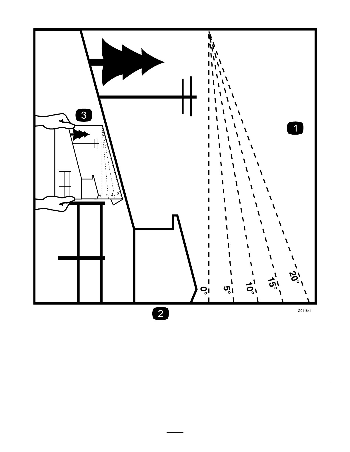
SlopeIndicator
G011841
Figure3
Thispagemaybecopiedforpersonaluse.
1.Themaximumslopeyoucansafelyoperatethemachineonis15degrees.Usetheslopecharttodeterminethedegreeofslope
ofhillsbeforeoperating.Donotoperatethismachineonaslopegreaterthan15degrees.Foldalongtheappropriateline
tomatchtherecommendedslope.
2.Alignthisedgewithaverticalsurface,atree,building,fencepole,etc.
3.Exampleofhowtocompareslopewithfoldededge.
7
Page 8
SafetyandInstructionalDecals
Safetydecalsandinstructionsareeasilyvisibletotheoperatorandarelocatednearanyareaofpotential
danger.Replaceanydecalthatisdamagedorlost.
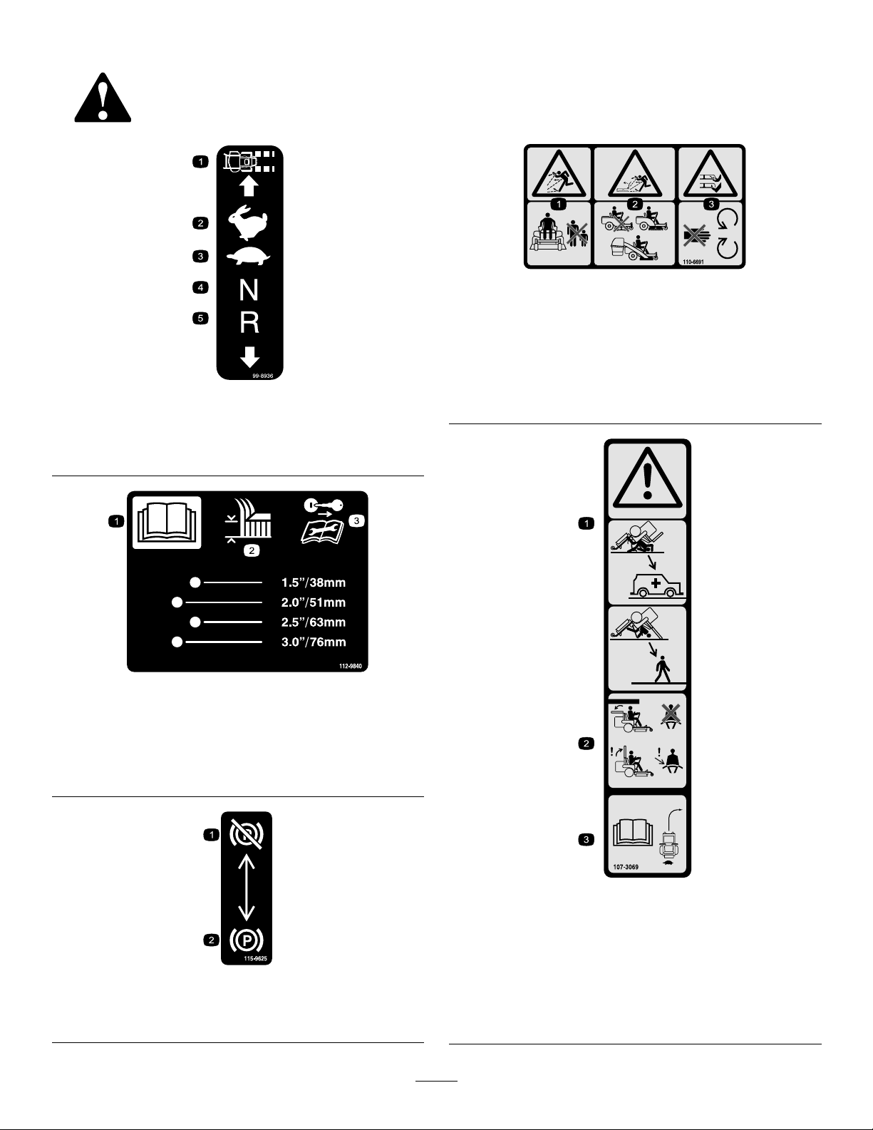
99-8936
1.Machinespeed4.Neutral
2.Fast5.Reverse
3.Slow
110-6691
1.Thrownobjecthazard—keepbystandersasafedistance
fromthemachine.
2.Thrownobjecthazard,mower—donotoperatewithoutthe
deector,dischargecover,orgrasscollectionsystemin
place.
3.Cutting/dismembermentofhandorfoot—stayawayfrom
movingparts.
1.ReadtheOperator's
Manual.
2.Heightofcut
1.Parking
brake—disengaged
112-9840
3.Removetheignitionkey
andreadtheinstructions
beforeservicingor
performingmaintenance.
115-9625
2.Parkingbrake—engaged
107-3069
1.Warning–thereisnorolloverprotectionwhentherollbaris
down.
2.Toavoidinjuryordeathfromarolloveraccident,keepthe
rollbarinthefullyraisedandlockedpositionandwear
theseatbelt.Lowertherollbaronlywhenabsolutely
necessary;donotwearthetheseatbeltwhentherollbaris
down.
3.ReadtheOperator'sManual;driveslowlyandcarefully.
8
Page 9
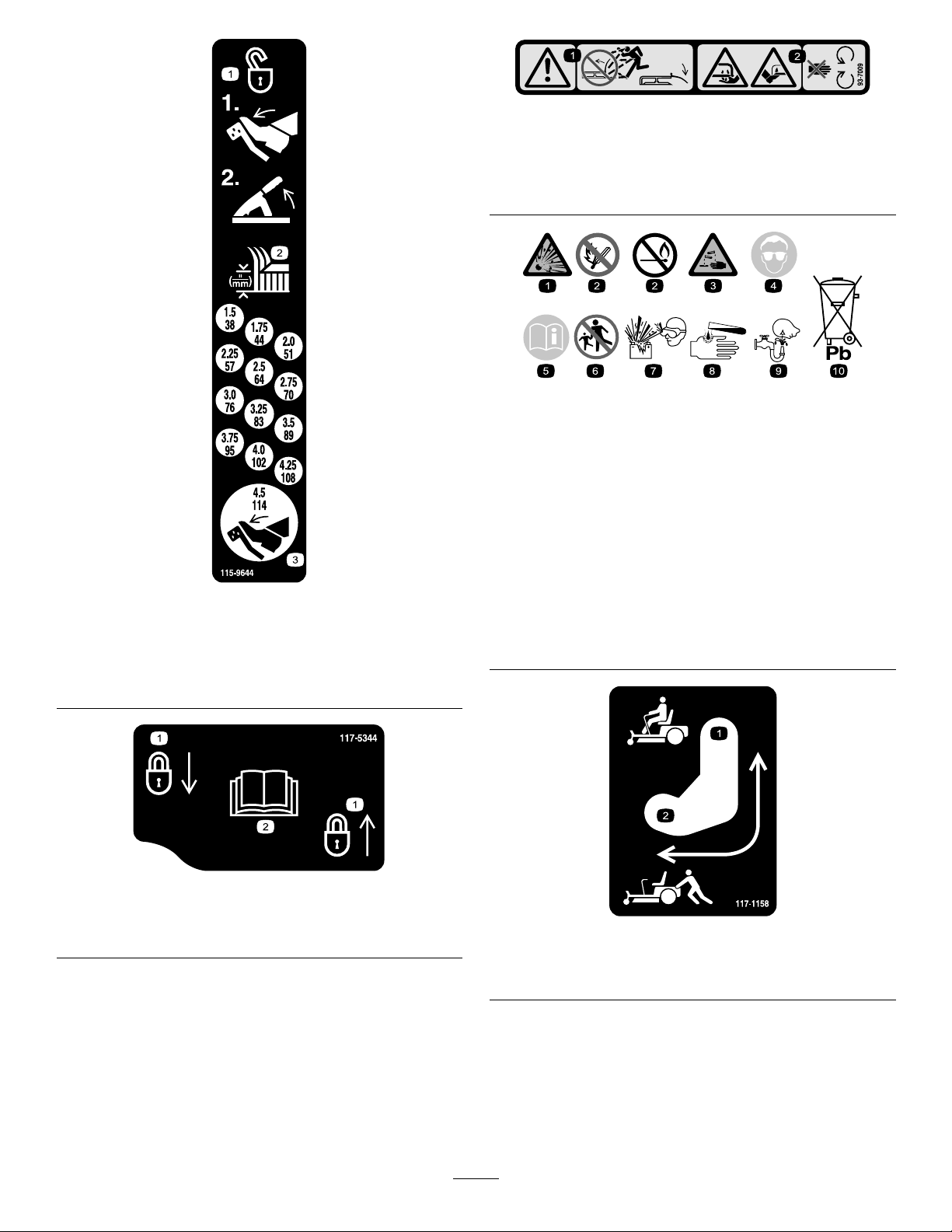
93-7009
1.Warning—donotoperatethemowerwiththedeectorup
orremoved;keepthedeectorinplace.
2.Cutting/dismembermenthazardofhandorfoot,mower
blade—stayawayfrommovingparts.
BatterySymbols
Someorallofthesesymbolsareonyourbattery
115-9644
1.Pressthepedalandlifttheheightofcutlevertounlockthe
deckposition.
2.Heightofcut
3.Pressthepedaltomovethedecktothetransportposition
117-5344
1.Explosionhazard
2.Nore,opename,or
smoking.
3.Causticliquid/chemical
burnhazard
4.Weareyeprotection.9.Flusheyesimmediately
5.ReadtheOperator's
Manual.
6.Keepbystandersasafe
7.Weareyeprotection;
8.Batteryacidcancause
10.Containslead;donot
distancefromthebattery .
explosivegasescan
causeblindnessandother
injuries.
blindnessorsevereburns.
withwaterandgetmedical
helpfast.
discard.
1.Lock
2.ReadtheOperator'sManual
1.Bypassleverpositionfor
operatingthemachine.
9
117–1158
2.Bypassleverpositionfor
pushingthemachine.
Page 10
Manufacturer'sMark
1.Indicatesthebladeisidentiedasapartfromtheoriginal
machinemanufacturer.
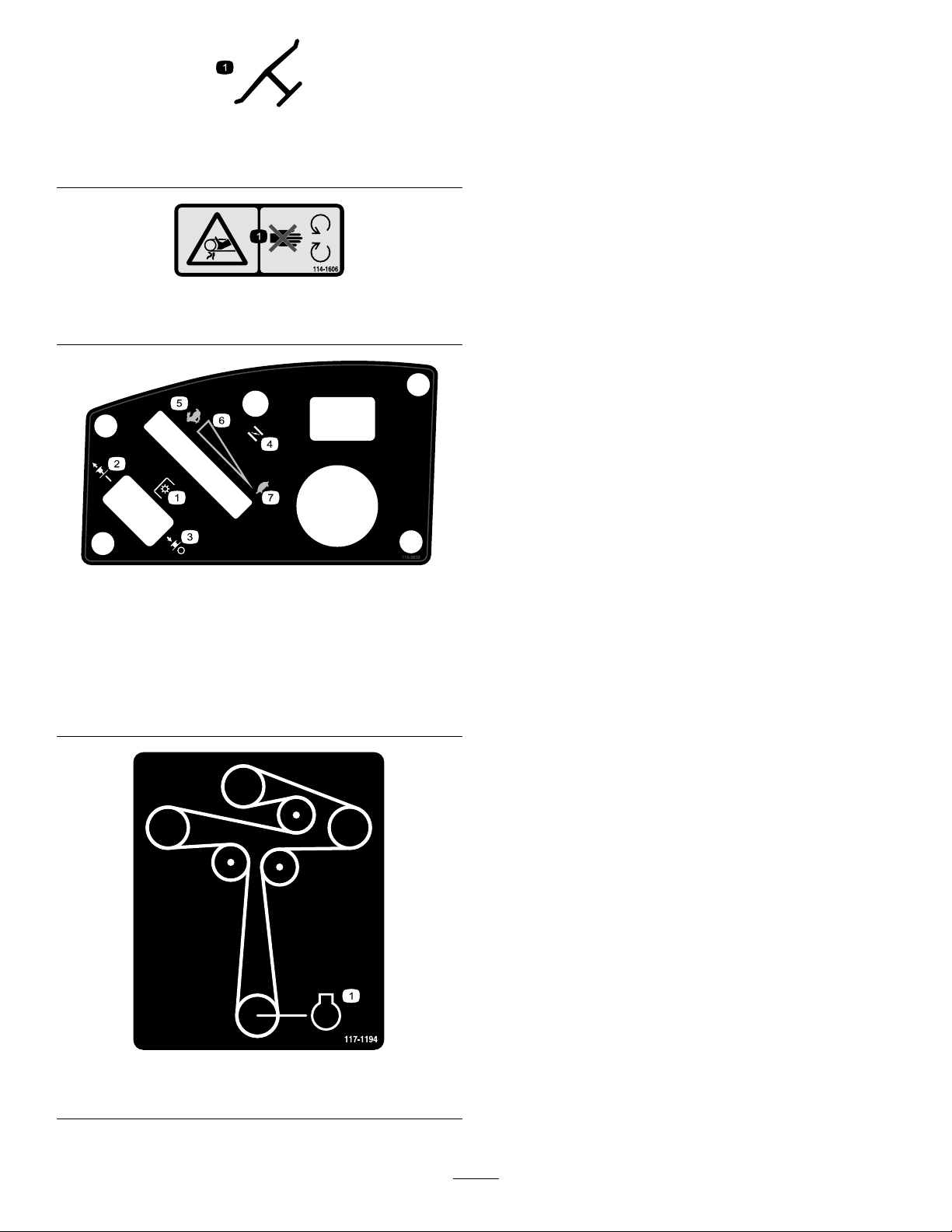
114-1606
1.Entanglementhazard,belt—keepallguardsinplace.
115-9632
1.Powertake-off(PTO),
Bladecontrolswitchon
somemodels
2.Bladecontrolswitch—On6.Continuousvariable
3.Bladecontrolswitch—Off7.Slow
4.Choke
5.Fast
setting
117-1194
1.Engine
10
Page 11
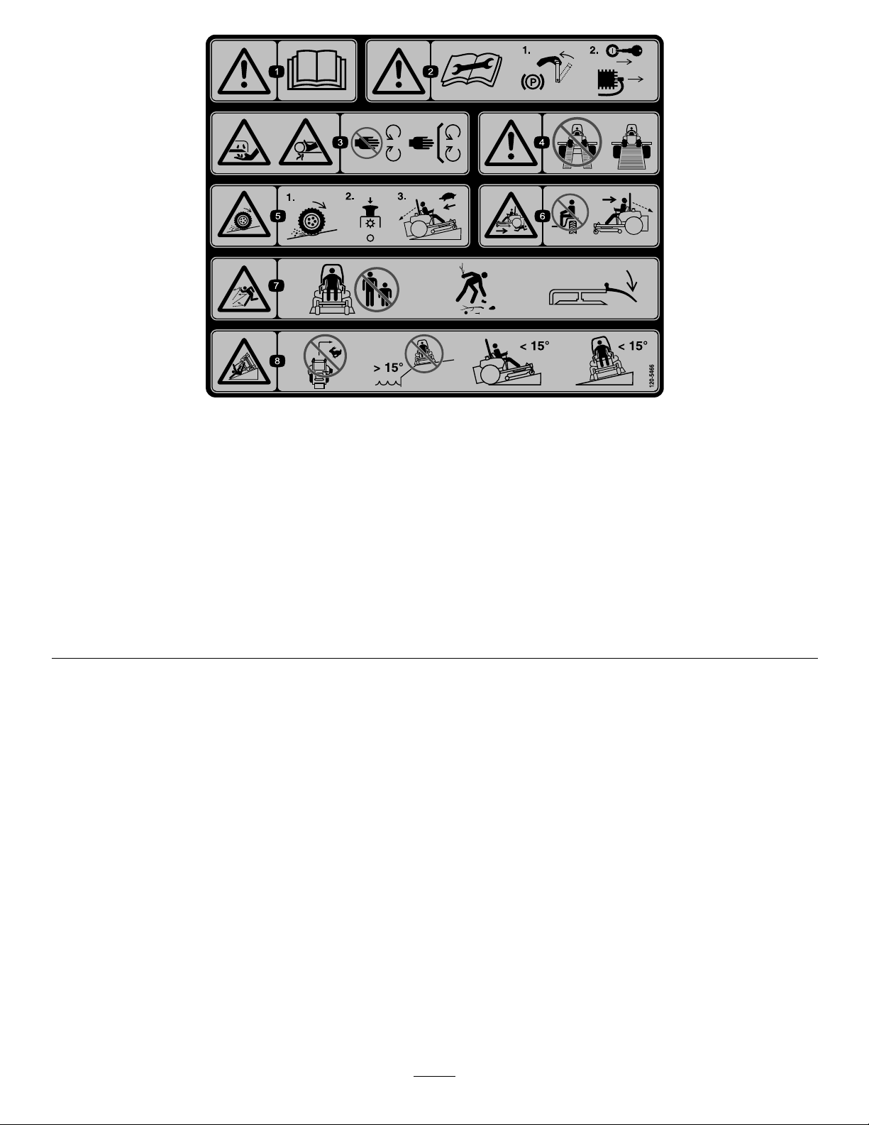
120-5466
1.Warning—readtheOperator'sManual.5.Lossoftraction/controlhazard,slopes—lossoftraction/control
2.Warning—readtheinstructionsbeforeservicingorperforming
maintenance;movethemotioncontrolleverstothepark
(brake)position,removetheignitionkeyanddisconnectthe
sparkplugwire.
3.Cutting/dismembermenthazard,mowerblade;entanglement
hazard,belt—stayawayfrommovingparts,keepallguards
andshieldsinplace.
4.Warning—donotusesplitramps,useafullrampswhen
transportingmachine.
onaslope,disengagethebladecontrolswitch(PTO),
proceedofftheslopeslowly .
6.Crushing/dismembermenthazardofbystanders,
reversing—donotcarrypassengers,lookbehindanddown
whenreversing.
7.Thrownobjecthazard—keepbystandersasafedistancefrom
themachine,pickupdebrisbeforeoperating,keepdeector
inplace.
8.Tippinghazard—donotturnathighspeeds,donotoperate
neardrop-offsonslopesgreaterthan15degrees,donotmow
slopesgreaterthan15degrees,avoidsuddenandsharp
turnswhileonslopes.
11
Page 12

115-9630
1.ReadtheOperator'sManualbeforeperformingany
maintenance.
2.Checktheengineoilevery8hours5.Checkthecasterwheeltirepressureevery25hours
3.Checkthedrivewheeltirepressureevery25hours
4.Checkthehydraulicoilevery25hours
6.Lubricatethecasterwheelevery25hours
119-8983
1.Fuel2.Full
3.Half
4.Empty
12
Page 13

119-8986
1.Fuel2.Full
3.Half
4.Empty
13
Page 14
ProductOverview
G015763
1
2
3
4
5
6
7
8
9
10
G014766
1
2
3
4
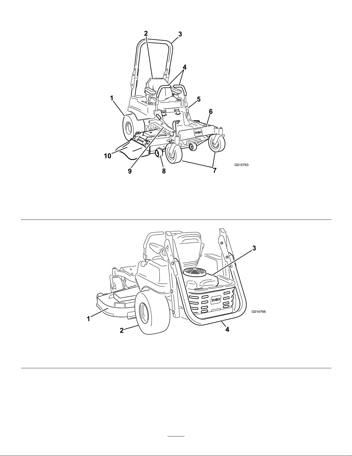
Figure4
1.Drivewheel4.Motioncontrollevers7.Frontcasterwheel
2.Operatorseat
3.Rolloverprotectionsystem
(ROPS)
1.MowerDeck3.Engine
2.Drivewheel
5.Parkingbrake8.Anti-scalproller
6.Footrest
9.Footpedaldeckliftand
height-of-cut
Figure5
4.Rolloverprotectionsystem(ROPS),foldeddown
10.Deector
14
Page 15
Controls
g017722
1
2
3
4
5
g020264
1
FuelGauge
Becomefamiliarwithallthecontrolsbeforeyoustartthe
engineandoperatethemachine(Figure6).
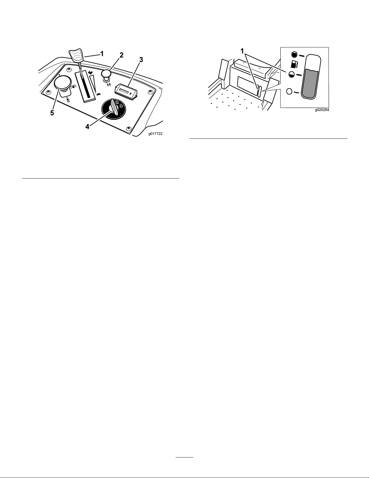
Figure6
1.Throttlecontrol4.Ignitionswitch
2.Choke5.Bladecontrolswitch(PTO)
3.Hourmeter
IgnitionSwitch
Theignitionswitchhasthreepositions:Start,RunandOff.
ThekeywillturntoStartandmovebacktoRunuponrelease.
TurningthekeytotheOffpositionwillstoptheengine;
however,alwaysremovethekeywhenleavingthemachineto
preventtheenginefromaccidentallystarting(Figure6).
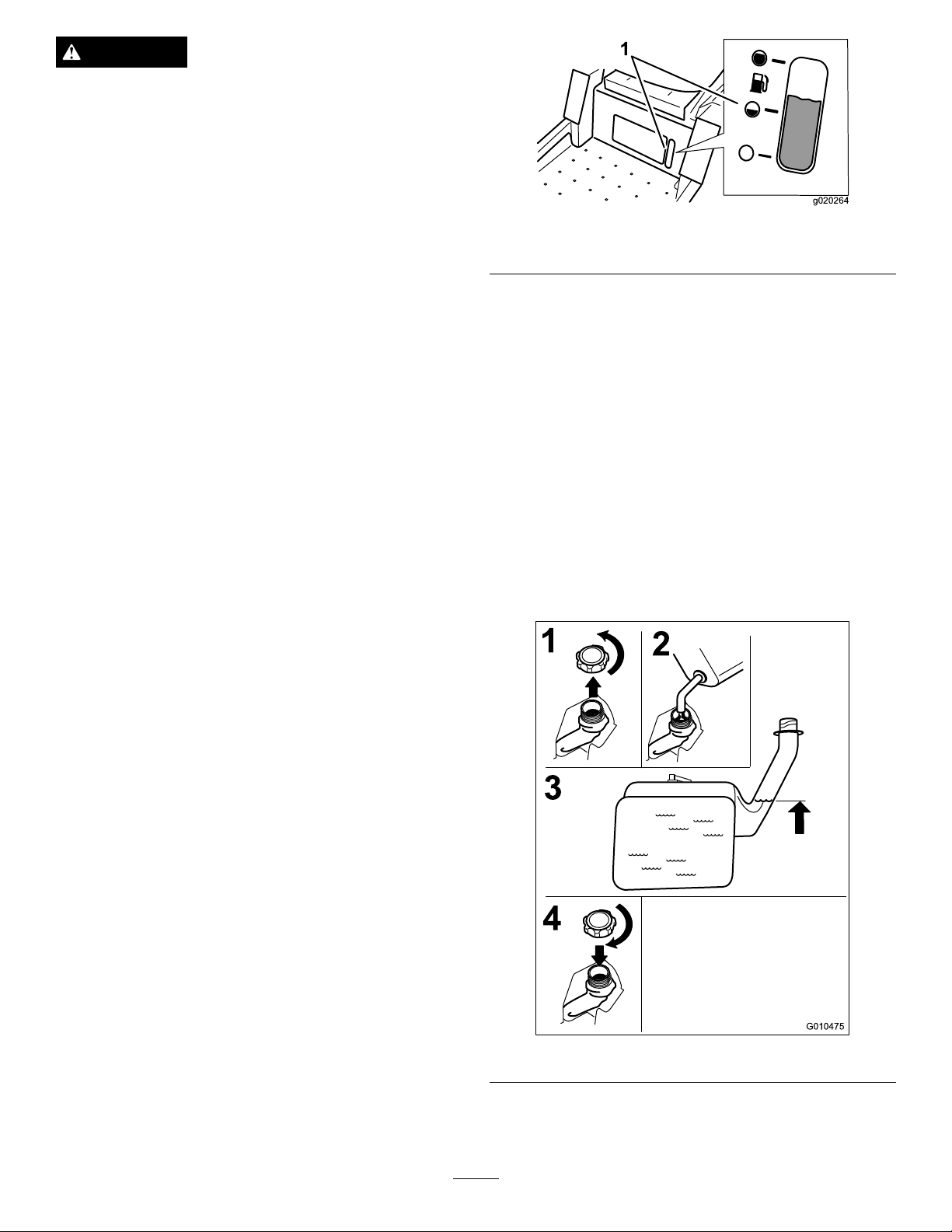
Thefuelwindowlocatedbelowtheoperatorpositioncanbe
usedtoverifythelevelofgasolineinthetank(Figure7).
Figure7
1.Fuelgaugewindow
MotionControlLevers
Themotioncontrolleversarespeedsensitivecontrolsof
independentwheelmotors.Movingaleverforwardor
backwardturnsthewheelonthesamesideforwardorin
reverse;wheelspeedisproportionaltotheamountthelever
ismoved.Movethecontrolleversoutwardfromthecenter
totheneutrallockpositionandexitthemachine(Figure4).
Alwayspositionthemotioncontrolleversintotheneutrallock
positionwhenyoustopthemachineorleaveitunattended.
ParkingBrakeLever
ThrottleControl
ThethrottlecontrolisvariablebetweenFastandSlow.
Movingthrottleleverforwardwillincreaseenginespeedand
movingthrottlelevertotherearwilldecreaseenginespeed.
Movingthethrottleforwardintothedetentisfullthrottle
(Figure6).
Choke
Usethechoketostartacoldengine.Pullthechokeknobup
toengageit.Pushdownonthechokeknobtodisengageit.
BladeControlSwitch(PowerTake-Off)
Thebladecontrolswitch,representedbyapowertake-off
(PTO)symbol,engagesanddisengagespowertothemower
blades(
HourMeter
Thehourmeterrecordsthenumberofhoursthebladeshave
operated.Itoperateswhenthebladecontrolswitch(PTO)is
engaged.Usethesetimesforschedulingregularmaintenance
(Figure6).
Figure6).
Locatedonleftsideoftheconsole(Figure4).Thebrakelever
engagesaparkingbrakeonthedrivewheels.Pulltheleverup
andrearwardtoengagethebrake.Pushtheleverforwardand
downtodisengagethebrake.
FootPedalDeckLiftSystem
Thefootpedaldeckliftsystemallowstheoperatortolower
andraisethedeckfromtheseatedposition.Theoperatorcan
usethefootpedaltoliftthedeckbrieytoavoidobstacles
orlockthedeckinthehighestheight-of-cutortransport
position(Figure4).
Height-of-CutLever
Theheight-of-cutleverworkswiththefootpedaltolockthe
deckinaspeciccuttingheight.Onlyadjusttheheightofcut
whilemachineisnotmoving(Figure4).
Attachments/Accessories
AselectionofToroapprovedattachmentsandaccessoriesare
availableforusewiththemachinetoenhanceandexpand
itscapabilities.ContactyourAuthorizedServiceDealeror
Distributororgotowww .Toro.comforalistofallapproved
attachmentsandaccessories.
15
Page 16

Operation
G015033
1
2
3
G015034
Note:Determinetheleftandrightsidesofthemachine
fromthenormaloperatingposition.
UsingtheRolloverProtection System(ROPS)
WARNING
ThinkSafetyFirst
Pleasecarefullyreadallofthesafetyinstructionsanddecals
inthesafetysection.Knowingthisinformationcouldhelp
you,yourfamily,petsorbystandersavoidinjury.
DANGER
Mowingonwetgrassorsteepslopescancause
slidingandlossofcontrol.
Wheelsdroppingoveredgescancauserollovers,
whichmayresultinseriousinjury,deathor
drowning.
Alossoftractionisalossofsteeringcontrol.
Toavoidlossofcontrolandpossibilityofrollover:
•Donotmowneardrop-offsornearwater.
•Donotmowslopesgreaterthan15degrees.
•Reducespeedanduseextremecautionon
slopes.
•Whenmowingslopes,graduallyworkfrom
lowertohigherareasontheincline.
•Avoidsuddenturnsorrapidspeedchanges.
•Turnup,intoaninclinewhenchanging
directionsonslopes.Turningdowntheslope
reducestraction.
•Attachmentschangethehandlingcharacteristics
ofthemachine.Useextracautionwhenusing
attachmentswiththemachine.
Toavoidinjuryordeathfromrollover:keepthe
rollbarintheraisedlockedpositionandusethe
seatbelt.
WARNING
Thereisnorolloverprotectionwhentherollbaris
inthedownposition.
•Lowertherollbaronlywhenabsolutely
necessary.
•Donotweartheseatbeltwhentherollbaris
inthedownposition.
•Driveslowlyandcarefully.
•Raisetherollbarassoonasclearancepermits.
•Checkcarefullyforoverheadclearances(i.e.
branches,doorways,electricalwires)before
drivingunderanyobjectsanddonotcontact
them.
Important:Lowertherollbaronlywhenabsolutely
necessary.
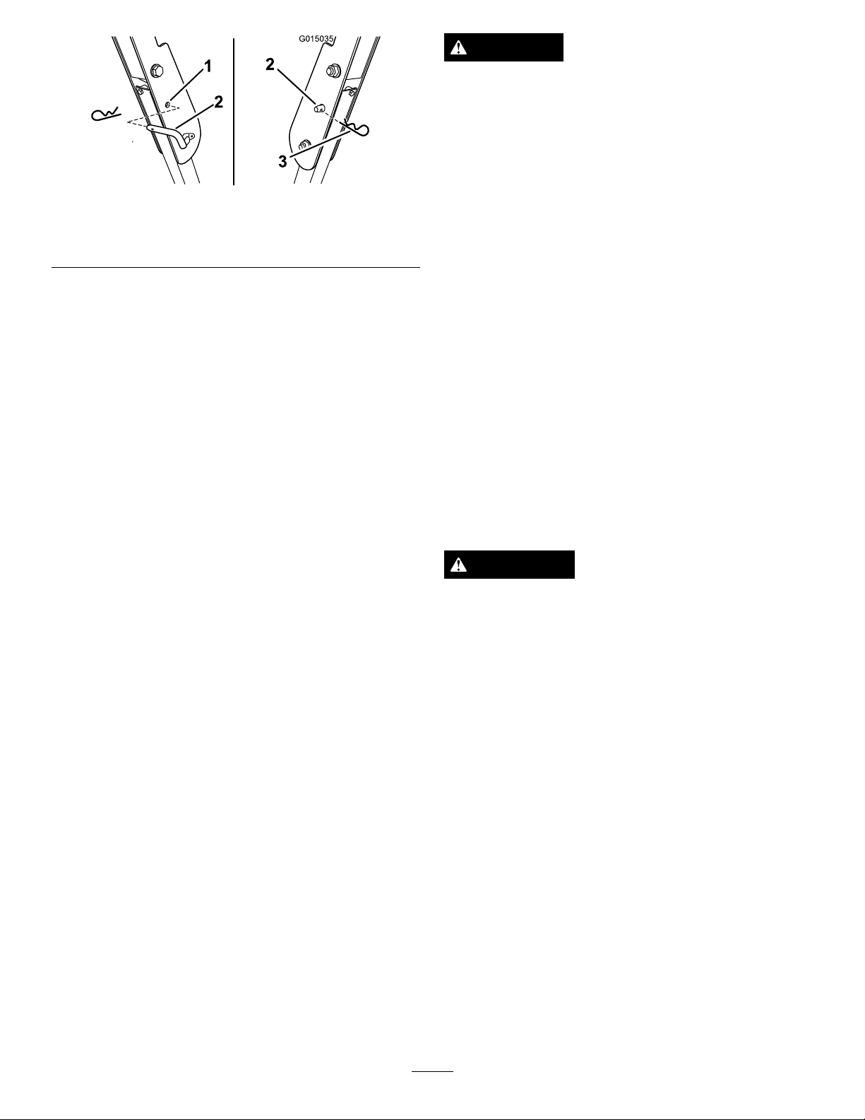
1.Toraisetherollbar,removethehaircotterpinand
removethelockingpins.
2.Raisetherollbartotheuprightposition(Figure9).
Figure8
1.SafeZone-usethemachinehere
2.Usewalkbehindmowerand/orhandtrimmerneardrop-offs
andwater.
3.Water
16
Important:Alwaysusetheseatbeltwiththeroll
barintheraisedposition.
3.Installthelockingpins.Securethepinsbyinstallingthe
haircotterpin(
Figure9
Figure10).
Page 17
G015035
1
2
3
2
Figure10
DANGER
Incertainconditionsduringfueling,static
electricitycanbereleasedcausingasparkwhich
canignitethegasolinevapors.Areorexplosion
fromgasolinecanburnyouandothersandcan
damageproperty.
•Alwaysplacegasolinecontainersontheground
awayfromyourvehiclebeforelling.
1.HoleinROPS
2.Lockingpin
4.Tolowertherollbar,removethehaircotterpinand
removethelockingpin.(Figure10).
5.Lowertherollbartothedownposition.
6.Usethetwolockingandcotterpinstosecurethebar.
3.Hairpincotter
AddingFuel
•Forbestresults,useonlyclean,fresh,unleadedgasoline
withanoctaneratingof87orhigher((R+M)/2rating
method).
•Oxygenatedfuelwithupto10%ethanolor15%MTBE
byvolumeisacceptable.
•DoNotuseethanolblendsofgasoline(suchasE15
orE85)withmorethan10%ethanolbyvolume.
Performanceproblemsand/orenginedamagemayresult
whichmaynotbecoveredunderwarranty.
•DoNotusegasolinecontainingmethanol.
•DoNotstorefueleitherinthefueltankorfuelcontainers
overthewinterunlessafuelstabilizerisused.
•DoNotaddoiltogasoline.
•Donotllgasolinecontainersinsideavehicleor
onatruckortrailerbedbecauseinteriorcarpets
orplastictruckbedlinersmayinsulatethe
containerandslowthelossofanystaticcharge.
•Whenpractical,removegas-poweredequipment
fromthetruckortrailerandrefueltheequipment
withitswheelsontheground.
•Ifthisisnotpossible,thenrefuelsuch
equipmentonatruckortrailerfromaportable
container,ratherthanfromagasolinedispenser
nozzle.
•Ifagasolinedispensernozzlemustbeused,
keepthenozzleincontactwiththerimofthe
fueltankorcontaineropeningatalltimesuntil
fuelingiscomplete.
WARNING
Gasolineisharmfulorfatalifswallowed.Long-term
exposuretovaporscancauseseriousinjuryand
illness.
•Avoidprolongedbreathingofvapors.
•Keepfaceawayfromnozzleandgastankor
conditioneropening .
•Keepgasawayfromeyesandskin.
17
Page 18
DANGER
g020264
1
G010475
1
2
4
3
Incertainconditions,gasolineisextremely
ammableandhighlyexplosive.Areorexplosion
fromgasolinecanburnyouandothersandcan
damageproperty.
•Fillthefueltankoutdoors,inanopenarea,
whentheengineiscold.Wipeupanygasoline
thatspills.
•Neverllthefueltankinsideanenclosedtrailer.
•Donotllthefueltankcompletelyfull.Add
gasolinetothefueltankuntilthelevelis1/4to
1/2inch(6to13mm)belowthebottomofthe
llerneck.Thisemptyspaceinthetankallows
gasolinetoexpand.
•Neversmokewhenhandlinggasoline,andstay
awayfromanopenameorwheregasoline
fumesmaybeignitedbyaspark.
•Storegasolineinanapprovedcontainerand
keepitoutofthereachofchildren.Neverbuy
morethana30-daysupplyofgasoline.
•Donotoperatewithoutentireexhaustsystemin
placeandinproperworkingcondition.
Figure11
1.Fuelgaugewindow
FillingtheFuelTank
Makesuretheengineisshutoffandthemotioncontrolsare
intheparkposition.
Important:DoNotoverllfueltank.Fillthefueltank
tothebottomofthellerneck.Theemptyspaceinthe
tankallowsthefueltoexpand.Overllingmayresultin
fuelleakageordamagetotheengineoremissionsystem.
1.Cleanaroundthefueltankcapandremovethecap.
Note:Youcanusethefuelwindowbelowthe
operatingpositionverifythepresenceofgasoline
beforellingthetank(
Figure11).
UsingStabilizer/Conditioner
Useafuelstabilizer/conditionerinthemachinetoprovide
thefollowingbenets:
•Keepsgasolinefreshduringstorageof90daysorless.
Forlongerstorageitisrecommendedthatthefueltank
bedrained.
•Cleanstheenginewhileitruns
•Eliminatesgum-likevarnishbuildupinthefuelsystem,
whichcauseshardstarting
Important:Donotusefueladditivescontaining
methanolorethanol.
Addthecorrectamountofgasstabilizer/conditionertothe
gas.
Note:Afuelstabilizer/conditionerismosteffectivewhen
mixedwithfreshgasoline.T ominimizethechanceofvarnish
depositsinthefuelsystem,usefuelstabilizeratalltimes.
FuelGauge
2.Slowlyaddregular,unleadedgasolineuntilthefuel
reachesthebaseofthellerneck
Figure12.
Usethefuelwindowbelowtheoperatortoverifythelevelof
gasolinebeforellingthetank(Figure11).
Figure12
3.Installthefueltankcapsecurelyandtightenuntilit
“clicks”.Wipeupanygasolinethatmayhavespilled.
18
Page 19

CheckingtheEngineOilLevel
G010078
1
2
G010079
1
2
G008946
G008959
1
2
OperatingtheChoke
Beforeyoustarttheengineandusethemachine,checktheoil
levelintheenginecrankcase;refertoCheckingtheEngine
OilLevel.
OperatingtheParkingBrake
Alwayssettheparkingbrakewhenyoustopthemachineor
leaveitunattended.
SettingtheParkingBrake
Figure13
Usethechoketostartacoldengine.
1.Iftheengineiscold,usethechoketostarttheengine.
2.Pulluponthechokeknobtoengagethechokebefore
usingtheignitionswitch(
3.Pushdownonthechoketodisengagethechokeafter
theenginehasstarted(Figure16).
Figure16).
ReleasingtheParkingBrake
Figure16
1.On2.Off
OperatingtheIgnitionSwitch
Figure14
OperatingtheThrottle
ThethrottlecontrolcanbemovedbetweenFastandSlow
positions(Figure15).
Alwaysusethefastpositionwhenturningonthemowerdeck
withthebladecontrolswitch(PTO).
1.TurntheignitionkeytotheStartposition(Figure17).
Whentheenginesstarts,releasethekey .
Important:Donotengagestarterformorethan5
secondsatatime.Iftheenginefailstostartallow
a15secondcool-downperiodbetweenattempts.
Failuretofollowtheseinstructionscanburnout
thestartermotor.
Note:Additionalstartingcyclesmayberequired
whenstartingtheengineforthersttimeafterthefuel
systemhasbeenwithoutfuelcompletely.
Figure15
19
Page 20

START
RUN
STOP
G008947
G010080
2
3
4
5
1
START
RUN
STOP
G008947
Figure17
2.Turntheignitionkeytostoptostoptheengine.
StartingandStoppingthe Engine
StartingtheEngine
1.Sitdownontheseat(Figure18)andfastentheseatbelt.
2.Movethemotioncontrolsoutwardtotheneutrallock
position(Figure18).
3.Settheparkingbrake(
ParkingBrake.
4.Movethebladecontrolswitch(PTO)totheOff
position(Figure18).
5.MovethethrottlelevertoFast.
6.EngagethechokeasdescribedinOperatingtheChoke.
Note:Awarmorhotenginemaynotrequirechoking.
Inthiscase,rsttrystartingtheenginewithoutusing
thechoke.
Figure18);refertoSettingthe
Figure18
7.TurntheignitionkeytotheStartposition(Figure17).
Whentheenginesstarts,releasethekey .
Important:Donotengagestarterformorethan5
secondsatatime.Iftheenginefailstostartallow
a15secondcool-downperiodbetweenattempts.
Failuretofollowtheseinstructionscanburnout
thestartermotor.
Note:Additionalstartingcyclesmayberequired
whenstartingtheengineforthersttimeafterthefuel
systemhasbeenwithoutfuelcompletely.
Figure19
1.Off3.Start
2.Run
20
Page 21

StoppingtheEngine
S
T
A
R
T
R
U
N
S
T
O
P
G017771
2
3
4
5
1
G008945
G009174
WARNING
Childrenorbystandersmaybeinjuredifthey
moveorattempttooperatethemachinewhileitis
unattended.
Alwaysremovetheignitionkeyandmovethe
motioncontrolleversoutwardtotheparkposition
whenleavingthemachineunattended,evenifjust
forafewminutes.
Note:Engagingthebladecontrolswitch(PTO)withthe
throttlepositionathalforlesswillcauseexcessivewearto
thedrivebelts.
Figure21
DisengagingtheBladeControlSwitch
(PTO)
Figure20
OperatingtheMowerBlade ControlSwitch(PTO)
Thebladecontrolswitch(PTO)startsandstopsthemower
bladesandanypoweredattachments.
EngagingtheBladeControlSwitch
(PTO)
Engagethebladecontrolswitch(PTO)withthethrottle
positionatFast.
Figure22
TheSafetyInterlockSystem
WARNING
Ifsafetyinterlockswitchesaredisconnectedor
damagedthemachinecouldoperateunexpectedly
causingpersonalinjury.
•Donottamperwiththeinterlockswitches.
•Checktheoperationoftheinterlockswitches
dailyandreplaceanydamagedswitchesbefore
operatingthemachine.
UnderstandingtheSafetyInterlock
System
Thesafetyinterlocksystemisdesignedtopreventtheengine
fromstartingunless:
•Theparkingbrakeisengaged.
•Thebladesaredisengaged.
•Themotioncontrolleversareintheneutrallockposition.
Thesafetyinterlocksystemalsoisdesignedtostoptheengine
whenthecontrolleversareoutoftheneutrallockposition
21
Page 22

withtheparkingbrakeonorifyourisefromtheseatwhen
thebladesareengaged.
TestingtheSafetyInterlockSystem
Testthesafetyinterlocksystembeforeyouusethemachine
eachtime.Ifthesafetysystemdoesnotoperateasdescribed
below,haveanAuthorizedServiceDealerrepairthesafety
systemimmediately.
1.Whilesittingontheseat,engagetheparkingbrakeand
movethebladecontrolswitchtoOn.Trystartingthe
engine;theengineshouldnotcrank.
2.Whilesittingontheseat,engagetheparkingbrakeand
movethebladecontrolswitchtoOff.Moveeither
motioncontrollever(forwardorreverse).Trystarting
theengine;theengineshouldnotcrank.Repeatwith
theothermotioncontrollever.
3.Whilesittingontheseat,engagetheparkingbrake,
movethebladecontrolswitchtoOff,andlockthe
motioncontrolleversinneutral.Starttheengine.
Whiletheengineisrunning,releasetheparkingbrake,
engagethebladecontrolswitch,andriseslightlyfrom
theseat;theengineshouldstop.
UsingtheMotionControlLevers
4.Whilesittingontheseat,engagetheparkingbrake,
movethebladecontrolswitchtoOff,andlockthe
motioncontrolleversinneutral.Starttheengine.
Whiletheengineisrunning,centerthemotion
controls;theengineshouldstop.
DrivingForwardorBackward
Thethrottlecontrolregulatestheenginespeedasmeasured
inrpm(revolutionsperminute).Placethethrottlecontrolin
thefastpositionforbestperformance.Alwaysoperateinthe
fullthrottlepositionwhenmowing.
CAUTION
Machinecanspinveryrapidly.Operatormaylose
controlofmachineandcausepersonalinjuryor
damagetomachine.
•Usecautionwhenmakingturns.
•Slowthemachinedownbeforemakingsharp
turns.
Figure23
1.Motioncontrol
lever-neutrallockposition
2.Center,unlockedposition5.Frontofmachine
3.Forward
4.Backward
DrivingForward
Note:Theenginewillkillifthetractioncontrolleversare
movedwiththeparkingbrakeengaged.
1.Releasetheparkingbrake;refertoReleasingthe
ParkingBrakeinOperation.
2.Movetheleverstothecenter,unlockedposition.
3.Togoforward,slowlypushthemotioncontrollevers
forward(Figure24).
22
Page 23

G008952
G008953
StoppingtheMachine
WARNING
Childrenorbystandersmaybeinjuredifthey
moveorattempttooperatethemachinewhileitis
unattended.
Alwaysremovetheignitionkeyandmovethe
motioncontrolleversoutwardtotheparkposition
whenleavingthemachineunattended,evenifjust
forafewminutes.
Tostopthemachine,movethetractioncontrolleversto
neutralandmovetolockedposition,disengagetheblade
controlswitch(PTO),andturntheignitionkeytooff.
Settheparkingbrakewhenyouleavethemachine;referto
SettingtheParkingBrake.Remembertoremovethekeyfrom
theignitionswitch.
Figure24
DrivingBackward
1.Movetheleverstothecenter,unlockedposition.
2.Togobackward,slowlypullthemotioncontrollevers
rearward(
Figure25).
AdjustingtheHeightofCut
Themachineisequippedwithafootpedaldeckliftsystem.
Theoperatorcanusethefootpedaltoliftthedeckbrieyto
avoidobstaclesorlockthedeckinthehighestheight-of-cut
ortransportposition.Theoperatorcanusetheheightof
cutleverwiththefootpedaltolockthedeckinaspecic
cuttingheight.
UsingtheFootPedalDeckLiftSystem
Pressthepedaldowntoraisethedeck;continuetopress
thepedaluntilthedeckislockedinthetransportposition
Figure26.Pushonthedeckliftpedalwithyourfootandraise
theheight-of-cutleverslightlytodisengagethetransportlock.
Figure25
23
Page 24

G010219
G010236
1
2
3
4
5
Figure27
Figure26
TransportLockPosition
AdjustingtheHeight-of-Cut
Theheight-of-cutcanbeadjustedfrom1-1/2to4-1/2inch
(38to114mm)in1/4inch(6mm)incrementsbyrelocating
theheight-of-cutpinintodifferentholelocations.
1.Pushonthedeckliftpedalwithyourfootand
raisethemowerdecktothetransportposition(also
the4-1/2inch(114mm)cuttingheightposition)
(Figure27).
2.Toadjust,removethepinfromtheheight-of-cut
bracket(Figure27).
3.Selectaholeintheheight-of-cutsystemcorresponding
totheheight-of-cutdesiredand,insertthepin
(Figure27).
1.Deckliftpedal
2.Cutheightpin
3.Height-of-cutpositions
4.Lockposition.lowest
height-of-cut(useonlyfor
deckremoval)
5.Lockposition.transport
position
UsingtheLockPositions
Thedeckcanbelockedinthehighestheight-of-cutor
transportpositionorthelowestheight-of-cutposition.
Tolockthedeckinthetransportposition:
1.Pushonthedeckliftpedalwithyourfootandraisethe
mowerdecktothetransportposition(alsothe4.5inch
(114mm)cuttingheightposition)(Figure27).
2.Removethepinfromtheheight-of-cutbracket
(Figure27).
3.Selectthelowerholeonthelockdecalandinsertthe
pin(Figure27).
Tolockthedeckinthelowestheight-of-cutposition:
4.Pushonthedeckliftpedalwithyourfootandraisethe
height-of-cutleverslightlytodisengagethetransport
lock.Lowerthedeckslowlyuntilthepinmakescontact
withthelever.
1.Pushonthedeckliftpedalwithyourfootandraisethe
mowerdecktothetransportposition(alsothe4.5inch
(114mm)cuttingheightposition)(Figure27).
2.Removethepinfromtheheight-of-cutbracket
(Figure27).
3.Pushonthedeckliftpedalwithyourfootandlower
themowerdecktothelowestposition.
4.Selecttheupperholeonthelockdecalandinsertthe
pin(
Figure27).
24
Page 25

AdjustingtheAnti-Scalp
G010233
1
2
3
4
G010232
1
4
1
2
G015764
3
5
AdjustingtheMotionControl
Rollers
Wheneveryouchangetheheight-of-cut,itisrecommended
toadjusttheheightoftheanti-scalprollers.
1.Disengagethebladecontrolswitch(PTO),movethe
motioncontrolleverstotheneutrallockpositionand
settheparkingbrake.
2.Stoptheengine,removethekey,andwaitforallmoving
partstostopbeforeleavingtheoperatingposition.
3.Adjusttheanti-scalprollersasshownin
matchtheclosestheight-of-cutposition.
Figure28
Figure28to
Levers
AdjustingtheHeight
Themotioncontrolleverscanbeadjustedhigherorlowerfor
maximumoperatorcomfort.
1.Removethe2boltsand2washersholdingthecontrol
levertothecontrolarmshaft(Figure30).
2.Movethecontrollevertothenextsetofholes.Secure
theleverwiththe2boltsand2washers(Figure30).
Figure30
1.Controlarmshaft
2.Controllever
3.Slotted,upperhole
4.Washer
5.Bolt
1.Anti-scalproller3.FlangeNut
2.Bolt4.Holespacing
PositioningtheSeat
Theseatcanmoveforwardandbackward.Positiontheseat
whereyouhavethebestcontrolofthemachineandaremost
comfortable.
Whilesittingintheoperator'sposition,raisetheseat
adjustmentleverslightlyandmovetheseatforwardor
backwardtothedesiredposition(Figure29).
1.Adjustmentlever
Figure29
3.Repeattheadjustmentfortheoppositecontrollever.
AdjustingtheTilt
Themotioncontrolleverscanbetiltedforeoraftfor
maximumoperatorcomfort.
1.Loosentheupperboltholdingthecontrollevertothe
controlarmshaft.
2.Loosenthelowerboltjustenoughtopivotthecontrol
leverforeoraft.Tightenbothboltstosecurethe
controlinthenewposition.
3.Repeattheadjustmentfortheoppositecontrollever.
PushingtheMachinebyHand
Important:Alwayspushthemachinebyhand.Never
towthemachinebecausedamagemayoccur.
ToPushtheMachine
1.Parkthemachineonalevelsurfaceanddisengagethe
bladecontrolswitch.
2.Movethemotioncontrolleversoutwardtoneutrallock
position,stoptheengine,removethekey,andwaitfor
allmovingpartstostopbeforeleavingtheoperating
position.Makesuretheparkingbrakeisdisengaged.
3.Locatethebypassleversattherearofthemachine,on
theleftandrightsideoftheframe.
25
Page 26

4.Movethebypassleversrearwardandthendowntolock
G012087
2
3
4
1
1
1
2
3
G012841
theminplaceasshowninFigure31todisengagethe
wheelmotors.Repeatthisoneachsideofthemachine.
Themachineisnowabletobepushedbyhand.
Figure31
2.Movethemotioncontrolleversoutwardtotheneutral
lockposition,settheparkingbrake,stoptheengine,
removethekey,andwaitforallmovingpartstostop
beforeleavingtheoperatingposition.
3.RemovethemowerasdescribedintheRemovingthe
MowerprocedureintheMaintenancesectionformore
information.
4.Turnthemowerupsidedown.
5.Removetheexistingmowerbladesinstalledonyour
deck.RefertotheRemovingtheBladesprocedurein
theMaintenancesectionformoreinformation.
6.Removethetwolocknuts(5/16inch)securedto
theweldedpostsoftheleftbafeonthetopofthe
mowerdeckatthecenterandleftofcenterpositions
Figure32).Removethecarriageboltandlocknuton
(
thesidewallofthemowerdecksecuringtheleftbafe
tothedeck.
ToOperatetheMachine
Movethebypasstothepositionforoperatingthemachine
Figure31)toengagethewheelmotors.
(
Convertingthe48inchMower toSideDischarge
Themowerdeckandmowerbladesshippedwiththismachine
weredesignedforoptimummulchingandsidedischarge
performance.
Installthefastenersintothesameholesinthedecktheywere
originallyremovedfrom.Thisensurenoholesareleftopen
whenthedeckisoperated.
DANGER
Openholesinthemowerexposeyouandothersto
throwndebris.Debristhrownoutofholesinthe
mowercancauseinjury.
•Neveroperatethemowerwithouthardware
mountedinallholesinthemower.
•Installhardwareinmountingholeswhenthe
bafeisremoved.
Figure32
1.Locknut(5/16inch)3.Leftbafe
2.Carriagebolt(5/16x3/4
inch)
7.Removetheleftbafefromthemowerdeckasshown
inFigure32.
8.Removethecarriagebolt(5/16x3/4inch)andlocknut
(5/16inch)ontherearwallofthemowerdecksecuring
thebafetothedeck(Figure33).
RemovingtheMulchBafe
1.Parkthemachineonalevelsurfaceanddisengagethe
bladecontrolswitch.
26
Page 27

G012806
1
2
3
4
3
2
1
2
3
G012805
G012800
1
2
3
4
Figure35
Figure33
1.Bafeguard3.Carriagebolt(5/16x3/4
2.Locknut(5/16inch)4.Rightbafe
inch)
9.Locatethebafeguardatthefrontedgeoftheside
dischargeopening.Removethefastenerssecuringthe
bafeguardandtherightbafetothemowerdeck
asshownin
Figure33.Removethebafeguardand
retainallfasteners.
10.Removethetwolocknuts(5/16inch)tosecuringthe
weldedpostsoftherightbafetothetopofthemower
deckatcenterandrightofcenterpositions(
Figure34).
Removetherightbafefromthemowerdeck.
1.Carriagebolt,existing3.Cutoffbafe,shipped
2.Rearholesinthe
dischargeplate
loose
4.Locknut,existing
12.Usethefastenersremovedtosecurethecutoffbafe
tothedeck.
13.Installthebladestothedeck.RefertotheInstalling
theBladesprocedureintheMaintenancesectionfor
moreinformation.
14.InstallthemowerasdescribedintheInstallingthe
MowerprocedureintheMaintenancesectionformore
information.
Convertingthe54inchMower toSideDischarge
Themowerdeckandmowerbladesshippedwiththis
machineweredesignedforoptimummulchingperformance.
Sidedischargeperformancecanbeimprovedbyreplacingthe
mulchingbladeswithstandardcuttingbladesobtainedfrom
yourlocalauthorizedT orodealer.Tomaintainoptimum
mulchingperformance,alwaysinstallthemulchingbladesthat
areshippedwiththisunitwhenchangingbacktomulching
operation.
Figure34
1.Locknut(5/16inch)3.Weldedposts,rightbafe
2.Rightbafe
11.Locatethecutoffbafeintheloosepartsbag.Remove
thefastenersattherearholesofthedischargeplate.
Installthebafeatthesidedischargeopeningonthe
mowerdeck(
Figure35).
Installthefastenersintothesameholesinthedecktheywere
originallyremovedfrom.Thisensurenoholesareleftopen
whenthedeckisoperated.
DANGER
Openholesinthemowerexposeyouandothersto
throwndebris.Debristhrownoutofholesinthe
mowercancauseinjury.
•Neveroperatethemowerwithouthardware
mountedinallholesinthemower.
•Installhardwareinmountingholeswhenthe
bafeisremoved.
27
Page 28

RemovingtheMulchBafe
G011149
1
1
2
3
4
G010712
1
2
4
3
5
6
7
1.Parkthemachineonalevelsurfaceanddisengagethe
bladecontrolswitch.
2.Movethemotioncontrolleversoutwardtotheneutral
lockposition,settheparkingbrake,stoptheengine,
removethekey,andwaitforallmovingpartstostop
beforeleavingtheoperatingposition.
3.RemovethemowerasdescribedintheRemovingthe
MowerprocedureintheMaintenancesectionformore
information.
4.Turnthemowerupsidedown.
5.Removetheexistingmowerbladesinstalledonyour
deck.RefertotheRemovingtheBladesprocedurein
theMaintenancesectionformoreinformation.
6.Removethethreelocknuts(5/16inch)securedtothe
weldedpostsoftheleftbafeonthetopofthemower
deckatthecenter,leftofcenterandleftpositions
(Figure36).Removethecarriageboltandlocknuton
thesidewallofthemowerdecksecuringtheleftbafe
tothedeck.
9.Removethecarriagebolt(5/16x3/4inch)andlocknut
(5/16inch)ontherearwallofthemowerdecksecuring
thebafetothedeck(Figure37).
Figure37
Figure36
1.Locknut(5/16inch)3.Leftbafe
2.Carriagebolt(5/16x3/4
inch)
4.Installfastenershere
7.Removetheleftbafefromthemowerdeckasshown
inFigure36.
8.Locatethetwoboltsinloosepartsandusetheexisting
locknuts.Installthesefastenersintotheholesshownin
Figure36onthemowerdecktopreventyingdebris.
Installtheboltup,throughtheundersideofthedeck
anduseanexistinglocknuttosecurefromthetopside.
1.Carriagebolt(5/16x3/4
inch)
2.Locknuts,frontof
dischargeplate(reinstall
afterbafeisremoved)
3.Locknut,forwardholein
deck(reinstallafterbafe
isremoved)
4.Bafeguard,54inch
decks
5.Hexheadbolt,forward
holeindeck(reinstallafter
bafeisremoved)
6.Carriagebolts,frontof
dischargeplate(reinstall
afterbafeisremoved)
7.Locknut(5/16inch)
10.Locatethebafeguardatthefrontedgeoftheside
dischargeopening.Removethefastenerssecuringthe
bafeguardandtherightbafetothemowerdeck
asshowninFigure37.Removethebafeguardand
retainallfasteners.
11.Removethetwolocknuts(5/16inch)securingthe
weldedpostsoftherightbafetothetopofthemower
deckatcenterandrightofcenterpositions(Figure38).
12.Removethecarriageboltandlocknutsecuringtheright
bafetothetopofthemowerdeck.Removetheright
bafefromthemowerdeck(Figure38).
WARNING
Openholesinthemowerexposeyouand
otherstothrowndebriswhichcancause
severeinjury.
•Neveroperatethemowerwithouthardware
mountedinallholesinthemowerhousing.
•Installthehardwareinthemountingholes
whenyouremovethemulchingbafe.
28
Page 29

G010704
1
2
3
Figure38
1.Locknut(5/16inch)3.Weldedposts,rightbafe
2.Rightbafe4.Carriagebolt
13.Installthefastenersremovedpreviouslyatthefront
holesinthedischargeplateandforwardholeinthe
deck(Figure37).
17.InstallthemowerasdescribedintheInstallingthe
MowerprocedureintheMaintenancesectionformore
information.
UsingtheSideDischarge
Themowerhasahingedgrassdeectorthatdisperses
clippingstothesideanddowntowardtheturf.
DANGER
Withoutagrassdeector,dischargecover,or
completegrasscatcherassemblymountedin
place,youandothersareexposedtobladecontact
andthrowndebris.Contactwithrotatingmower
blade(s)andthrowndebriswillcauseinjuryor
death.
•Neverremovethegrassdeectorfromthemower
becausethegrassdeectorroutesmaterialdown
towardtheturf.Ifthegrassdeectorisever
damaged,replaceitimmediately .
•Neverputyourhandsorfeetunderthemower.
14.Locatethecutoffbafeintheloosepartsbag.Remove
thefastenersattherearholesofthedischargeplate.
Installthebafeatthesidedischargeopeningonthe
mowerdeck(Figure39).
Figure39
1.Carriagebolt3.Cutoffbafe
2.Rearholesinthe
dischargeplate
4.Locknut
•Nevertrytoclearthedischargeareaormower
bladesunlessyoumovethebladecontrolswitch
(PTO)totheoffposition,rotatetheignitionkey
tooffandremovethekey.
•Makesurethegrassdeectorisinthedown
position.
15.Usethefastenersremovedtosecurethecutoffbafe
tothedeck.
16.Installthebladestothedeck.RefertotheInstalling
theBladesprocedureintheMaintenancesectionfor
moreinformation.
29
Page 30

OperatingTips
FastThrottleSetting
Forbestmowingandmaximumaircirculation,operate
theengineatthefastthrottleposition.Airisrequiredto
thoroughlycutgrassclippings,sodonotsettheheight-of-cut
solowastototallysurroundthemowerbyuncutgrass.
Alwaystrytohaveonesideofthemowerfreefromuncut
grass,whichallowsairtobedrawnintothemower.
setting.Thencutthegrassagainusingthelower,normal
setting.
WhenStopping
Ifthemachine'sforwardmotionmustbestoppedwhile
mowing,aclumpofgrassclippingsmaydropontoyour
lawn.Toavoidthis,moveontoapreviouslycutareawiththe
bladesengagedoryoucandisengagethemowerdeckwhile
movingforward.
CuttingaLawnfortheFirstTime
Cutgrassslightlylongerthannormaltoensurethecutting
heightofthemowerdoesnotscalpanyunevenground.
However,thecuttingheightusedinthepastisgenerallythe
bestonetouse.Whencuttinggrasslongerthansixinchestall,
youmaywanttocutthelawntwicetoensureanacceptable
qualityofcut.
Cut1/3oftheGrassBlade
Itisbesttocutonlyabout1/3ofthegrassblade.Cutting
morethanthatisnotrecommendedunlessgrassissparse,or
itislatefallwhengrassgrowsmoreslowly.
MowingDirection
Alternatemowingdirectiontokeepthegrassstanding
straight.Thisalsohelpsdisperseclippingswhichenhances
decompositionandfertilization.
MowatCorrectIntervals
Normally,moweveryfourdays.Butremember,grassgrows
atdifferentratesatdifferenttimes.Sotomaintainthesame
cuttingheight,whichisagoodpractice,mowmoreoftenin
earlyspring.Asthegrassgrowthrateslowsinmidsummer,
mowlessfrequently .Ifyoucannotmowforanextended
period,rstmowatahighcuttingheight;thenmowagain
twodayslateratalowerheightsetting.
KeeptheUndersideoftheMowerClean
Cleanclippingsanddirtfromtheundersideofthemower
aftereachuse.Ifgrassanddirtbuildupinsidethemower,
cuttingqualitywilleventuallybecomeunsatisfactory.
BladeMaintenance
Maintainasharpbladethroughoutthecuttingseasonbecause
asharpbladecutscleanlywithouttearingorshreddingthe
grassblades.Tearingandshreddingturnsgrassbrownat
theedges,whichslowsgrowthandincreasesthechanceof
disease.Checkthecutterbladesdailyforsharpness,andfor
anywearordamage.Filedownanynicksandsharpenthe
bladesasnecessary.Ifabladeisdamagedorworn,replaceit
immediatelywithagenuineTOROreplacementblade.
CuttingSpeed
Toimprovecutquality,useaslowergroundspeedincertain
conditions.
AvoidCuttingTooLow
Ifthecuttingwidthofthemoweriswiderthanthemower
youpreviouslyused,raisethecuttingheighttoensurethat
uneventurfisnotcuttooshort.
LongGrass
Ifthegrassiseverallowedtogrowslightlylongerthan
normal,orifitcontainsahighdegreeofmoisture,raisethe
cuttingheighthigherthanusualandcutthegrassatthis
30
Page 31

Maintenance
RecommendedMaintenanceSchedule(s)
MaintenanceService
Interval
Aftertherst8hours
Aftertherst50hours
Beforeeachuseordaily
Aftereachuse
Every25hours
Every50hours
Every100hours
Every200hours
Every400hours
MaintenanceProcedure
•Changetheengineoil.
•Changethehydraulicsystemlterandoil.
•Checkthesafetyinterlocksystem.
•Checktheengineoillevel.
•Cleantheairintakescreen.
•Checkthemowerblades.
•Inspectthegrassdeectorfordamage
•Cleanthemowerhousing.
•Greasealllubricationpoints.
•Checktirepressure.
•Checkthehydraulicoillevelintheexpansiontank.
•Inspectthebeltsforcracksandwear.
•Servicethepaperelement(moreoftenindusty,dirtyconditions).
•Changetheengineoil(moreoftenindusty,dirtyconditions).
•Checkthesparkplug(s).
•Replacethefuellters(moreoftenunderdusty,dirtyconditions).
•Replacethepaperelement(moreoftenindusty,dirtyconditions).
•Changetheoillter.(moreoftenindusty,dirtyconditions)
•Changethehydraulicsystemlterandoil.
Monthly
Yearlyorbeforestorage
•Checkthebatterycharge.
•Paintchippedsurfaces.
•Checkallmaintenanceprocedureslistedabovebeforestorage.
Important:Refertoyourengineoperator'smanualforadditionalmaintenanceprocedures.
CAUTION
Ifyouleavethekeyintheignitionswitch,someonecouldaccidentlystarttheengineandseriouslyinjure
youorotherbystanders.
Removethekeyfromtheignitionanddisconnectthewirefromthesparkplugbeforeyoudoany
maintenance.Setthewireasidesothatitdoesnotaccidentallycontactthesparkplug .
31
Page 32

Figure40
Locatedontheseatpanunderside
1.ReadtheOperator'sManualbeforeperformingany
maintenance.
2.Checktheengineoilevery8hours5.Checkthecasterwheeltirepressureevery25hours
3.Checkthedrivewheeltirepressureevery25hours
4.Checkthehydraulicoilevery25hours
6.Lubricatethecasterwheelevery25hours
32
Page 33

Premaintenance
G009949
1
Lubrication
Procedures
GreasingtheBearings
RaisingtheSeat
Makesurethemotioncontrolleversarelockedintheneutral
lockposition.Lifttheseatforward.
Thefollowingcomponentscanbeaccessedbyraisingtheseat:
•Servicedecal
•Fuses
•Batteryandcables
ServiceInterval:Every25hours—Greasealllubrication
points.
GreaseType:No.2GeneralPurposeLithiumBaseGrease
1.Parkthemachineonalevelsurfaceanddisengagethe
bladecontrolswitch.
2.Movethemotioncontrolleversoutwardtotheneutral
lockposition,stoptheengine,removethekey,and
waitforallmovingpartstostopbeforeleavingthe
operatingposition.
3.Cleanthegreasettings(Figure41andFigure40)with
arag.Makesuretoscrapeanypaintoffofthefront
ofthetting(s).
Figure41
1.Frontcastertire
4.Connectagreaseguntoeachtting(Figure40and
Figure41).Pumpgreaseintothettingsuntilgrease
beginstooozeoutofthebearings.
5.Wipeupanyexcessgrease.
33
Page 34

EngineMaintenance
G015155
1
2
3
SAEV iscosityGrades
SAE40
SAE30
SAE10W– 30/ SAE10W– 30
-2002032406080100
-30-20-10010203040
°F
°C
STARTING TEMPERA TURERANGE ANTICIPATEDBEFORENEXT OIL CHANGE
SAE5W– 20
G010686
WARNING
Contactwithhotsurfacesmaycausepersonal
injury.
Keephands,feet,face,clothingandotherbody
partsawaythemuferandotherhotsurfaces.
ServicingtheAirCleaner
CleaningtheElement
ServiceInterval:Every100hours—Servicethepaper
element(moreoftenindusty ,dirty
conditions).
Every200hours/Yearly(whichevercomes
rst)—Replacethepaperelement(moreoftenin
dusty,dirtyconditions).
1.Lightlytaptheelementonaatsurfacetoremovedust
anddirt.
2.Inspecttheelementfortears,anoilylm,anddamage
totheseal.
Note:Servicetheaircleanermorefrequently(everyfew
hours)ifoperatingconditionsareextremelydustyorsandy.
RemovingtheElement
1.Parkthemachineonalevelsurfaceanddisengagethe
bladecontrol(PTO).
2.Movethemotioncontrolleverstotheneutrallock
position,settheparkingbrake,stoptheengine,remove
thekey,andwaitforallmovingpartstostopbefore
leavingtheoperatingposition.
3.Cleanaroundtheaircleanercovertopreventdirtfrom
gettingintotheengineandcausingdamage.Liftthe
coverandremovethehoseclampsecuringtheair
cleanerassemblytotheengine(
4.Loosenthehoseclampandremovethepaperelement
(Figure42).
Figure42).
Important:Nevercleanthepaperelementwith
pressurizedairorliquids,suchassolvent,gas,
orkerosene.Replacethepaperelementifitis
damagedorcannotbecleanedthoroughly.
ServicingtheEngineOil
OilType:Detergentoil(APIserviceSF,SG,SH,SJ,orSL)
CrankcaseCapacity:61ounces(1.8l),[whenoillteris
removed:70ounces(2.1l)]
Viscosity:Seethetablebelow.
Figure42
1.Cover
2.Paperelement
3.Hoseclamp
Figure43
Note:Usingmultigradeoils(5W -20,10W-30,and10W -40)
willincreaseoilconsumption.Checkoillevelmorefrequently
whenusingthem.
CheckingtheEngineOilLevel
ServiceInterval:Beforeeachuseordaily
Note:Checktheoilwhentheengineiscold.
WARNING
Contactwithhotsurfacesmaycausepersonal
injury.
Keephands,feet,face,clothingandotherbody
partsawaythemuferandotherhotsurfaces.
Important:Donotoverllthecrankcasewithoil
becausedamagetotheenginemayresult.Donotrun
34
Page 35

enginewithoilbelowthelowmarkbecausetheengine
G008792
1
2
5
6
7
3
9
10
4
8
G012153
1
2
3
4
5 6
maybedamaged.
1.Parkthemachineonalevelsurface,disengagethe
bladecontrolswitch,stoptheengine,engageparking
brake,andremovethekey.
2.Makesuretheengineisstopped,level,andiscoolso
theoilhashadtimetodrainintothesump.
3.Tokeepdirt,grassclippings,etc.,outoftheengine,
cleantheareaaroundtheoilllcap/dipstickbefore
removingit.
4.Stoptheengine,removethekey ,andwaitforall
movingpartstostopbeforeleavingtheoperating
position(
Figure44).
Note:Disposeoftheusedoilatarecyclingcenter.
1.Parkthemachinesothatthedrainsideisslightly
lowerthantheoppositesidetoensuretheoildrains
completely.
2.DisengagethePTO,movethemotioncontrolleversto
theneutrallockedpositionandsettheparkingbrake.
3.Stoptheengine,removethekey ,andwaitforall
movingpartstostopbeforeleavingtheoperating
position(
Figure45).
ChangingtheEngineOil
ServiceInterval:Aftertherst8hours—Changetheengine
Every100hours—Changetheengineoil(moreoften
industy,dirtyconditions).
Figure45
4.Slowlypourapproximately80%ofthespeciedoil
Figure44
oil.
intothellertubeandslowlyaddtheadditionaloilto
bringittotheFullmark(Figure46).
35
Page 36

G008796
2
3
4
5
6
1
Figure46
G008748
3/4
1
2
3
4
5
6
ChangingtheEngineOilFilter
ServiceInterval:Every200hours—Changetheoillter.
(moreoftenindusty ,dirtyconditions)
Note:Changetheengineoilltermorefrequentlywhen
operatingconditionsareextremelydustyorsandy.
1.Draintheoilfromtheengine;refertoChangingthe
EngineOil.
2.Changetheengineoillter(Figure47).
Figure47
Note:Ensuretheoilltergaskettouchestheengine
andthenanextra3/4turniscompleted.
3.Fillthecrankcasewiththepropertypeofnewoil;refer
toChangingtheOil.
ServicingtheSparkPlug
ServiceInterval:Every100hours—Checkthesparkplug(s).
Makesuretheairgapbetweenthecenterandsideelectrodes
iscorrectbeforeinstallingthesparkplug.Useasparkplug
wrenchforremovingandinstallingthesparkplug(s)anda
gappingtool/feelergaugetocheckandadjusttheairgap.
Installanewsparkplug(s)ifnecessary.
Type:NGKBPR4ES(orequivalent)
AirGap:0.030inch(0.76mm)
RemovingtheSparkPlug
1.DisengagethePTO,movethemotioncontrolleversto
theneutrallockedpositionandsettheparkingbrake.
2.Stoptheengine,removethekey,andwaitforallmoving
partstostopbeforeleavingtheoperatingposition.
36
Page 37

Figure48
G008794
1
2
16ft-lb
22N-m
G010687
Note:Duetothedeeprecessaroundthesparkplug,
blowingoutthecavitywithcompressedairisusually
themosteffectivemethodforcleaning.Thesparkplug
ismostaccessiblewhentheblowerhousingisremoved
forcleaning.
CheckingtheSparkPlug
Important:Nevercleanthesparkplug(s).Always
replacethesparkplug(s)whenithas:ablackcoating,
wornelectrodes,anoilylm,orcracks.
Figure50
CleaningtheCoolingSystem
Ifyouseelightbrownorgrayontheinsulator,theengineis
operatingproperly.Ablackcoatingontheinsulatorusually
meanstheaircleanerisdirty.
Setthegapto0.030inches(0.76mm).
Figure49
InstallingtheSparkPlug
Tightenthesparkplug(s)to16ft-lb(22N-m).
Cleantheairintakescreenfromgrassanddebrisbeforeeach
use.
1.Disengagethebladecontrolswitchandmovethe
controlleverstotheneutrallockedpositionandapply
theparkingbrake.
2.Stoptheengine,removethekey,andwaitforallmoving
partstostopbeforeleavingtheoperatingposition.
3.Removetheairintakescreen,aircleanercover,and
fanhousing.
4.Cleandebrisandgrassfromtheparts.
5.Installtheairintakescreen,aircleanercover,andfan
housing.
37
Page 38

FuelSystem
g017723
1
2
3
4
5
G008963
12
3
Maintenance
ReplacingtheFuelFilter
ServiceInterval:Every100hours/Yearly(whichevercomes
rst)(moreoftenunderdusty,dirty
conditions).
1.Disengagethebladecontrolswitch(PTO),movethe
motioncontrolleverstotheneutrallockposition,and
settheparkingbrake.
2.Stoptheengine,removethekey,andwaitforallmoving
partstostopbeforeleavingtheoperatingposition.
3.Allowthemachinetocooldown.
4.Raisetheseatandlocatethefuelltersasshownin
Figure51.
Figure52
1.Fuellter
2.Hoseclamp
6.Removethelterfromthefuellines.
7.Installanewlterwiththeowdirectionarrowcoming
fromthefueltankandpointingtotheengine.Move
thehoseclampsclosetothelter(
itinplace.
3.Fuelline
Figure51)tosecure
Figure51
1.Fuellinefromtank
2.In-lineFuellter
3.Flowdirectionarrow
5.Squeezetheendsofthehoseclampstogetherandslide
themawayfromthelter(Figure52).
4.Fuellinetoengine
5.Hoseclamp
38
Page 39

ElectricalSystem
G010240
1
2
3
4
Maintenance
ServicingtheBattery
ServiceInterval:Monthly
DANGER
Batteryelectrolytecontainssulfuricacidwhichisa
deadlypoisonandcausessevereburns.
Donotdrinkelectrolyteandavoidcontactwith
skin,eyesorclothing.Wearsafetyglassestoshield
youreyesandrubberglovestoprotectyourhands.
Figure53
RemovingtheBattery
WARNING
Batteryterminalsormetaltoolscouldshortagainst
metalmachinecomponentscausingsparks.Sparks
cancausethebatterygassestoexplode,resulting
inpersonalinjury.
•Whenremovingorinstallingthebattery,donot
allowthebatteryterminalstotouchanymetal
partsofthemachine.
•Donotallowmetaltoolstoshortbetween
thebatteryterminalsandmetalpartsofthe
machine.
WARNING
Incorrectbatterycableroutingcoulddamagethe
machineandcablescausingsparks.Sparkscan
causethebatterygassestoexplode,resultingin
personalinjury.
•AlwaysDisconnectthenegative(black)battery
cablebeforedisconnectingthepositive(red)
cable.
•AlwaysReconnectthepositive(red)battery
cablebeforereconnectingthenegative(black)
cable.
1.Removethewingnutand
clamp
2.Removethenegative
batterycablebeforethe
positive
4.Removetheclamp(Figure53).
5.Firstdisconnectthenegativebatterycable(black)from
thenegative(-)(black)batteryterminal(
6.Slidetheredterminalbootoffthepositive(red)battery
terminalandremovethepositive(+)(red)batterycable
Figure53).
(
7.Removethebattery.
3.Removethepositive
batterycable
4.Removebattery
Figure53).
InstallingtheBattery
1.Positionbatteryinthetraywiththeterminalposts
oppositefromthefueltank(
2.First,installthepositive(red)batterycabletopositive
(+)batteryterminal.
3.Theninstallthenegativebatterycabletothenegative
(-)batteryterminal.
4.Securethecableswith2bolts,2washers,and2locknuts
Figure53).
(
5.Slidetheredterminalbootontothepositive(red)
batterypost.
6.Installtheclampandsecureitwiththewingnut
(Figure53).
Figure53).
1.Disengagethebladecontrolswitch(PTO),movethe
motioncontrolleverstotheneutrallockpositionand
settheparkingbrake.
2.Stoptheengine,removethekey,andwaitforallmoving
partstostopbeforeleavingtheoperatingposition.
3.Removethewingnutsecuringthebatteryclamp
(
Figure53).
ChargingtheBattery
WARNING
Chargingthebatteryproducesgassesthatcan
explode.
Neversmokenearthebatteryandkeepsparksand
amesawayfrombattery.
39
Page 40

Important:Alwayskeepthebatteryfullycharged.This
30
25
1 2
3
G015037
4
isespeciallyimportanttopreventbatterydamagewhen
thetemperatureisbelow32°F(0°C).
1.Chargebatteryfor10to15minutesat25to30amps
or30minutesat10amps.
2.Whenthebatteryisfullycharged,unplugthecharger
fromtheelectricaloutlet,thendisconnectthecharger
leadsfromthebatteryposts(Figure54).
3.Installthebatteryinthemachineandconnectthe
batterycables,refertoInstallingtheBattery.
Note:Donotrunthemachinewiththebattery
disconnected,electricaldamagemayoccur.
Figure55
Figure54
1.PositiveBatteryPost
2.NegativeBatteryPost
3.Red(+)ChargerLead
4.Black(-)ChargerLead
ServicingtheFuses
Theelectricalsystemisprotectedbyfuses.Itrequires
nomaintenance,however,ifafuseblowscheckthe
component/circuitforamalfunctionorshort.
Fuses:
•Main,30amp,blade-type
1.30amp
2.25amp4.Fuseblock
3.Openaccessoryslot
•Engine,20amp,blade-type
1.Thefusesarelocatedonrighthandconsolenextto
theseat(Figure55).
2.Toreplacethefuses,pulloutonthefusetoremoveit.
3.Installanewfuseofthesameamperageremoved
(Figure55).
40
Page 41

DriveSystem
G010253
1
2
3
HydraulicSystem
Maintenance
CheckingtheTirePressure
ServiceInterval:Every25hours—Checktirepressure.
Maintaintheairpressureinthefrontandreartiresas
specied.Uneventirepressurecancauseunevencut.Check
thepressureatthevalvestem(Figure56).Checkthetires
whentheyarecoldtogetthemostaccuratepressurereading.
Refertothemaximumpressuresuggestedbythetire
manufactureronthesidewallofthecasterwheeltires.
Inatethereardrivewheeltiresto13psi(90kPa).
Figure56
Maintenance
HydraulicSystemOilSpecication
OilType:ToroHYPR-OIL®500or20w-50motoroil.
SystemCapacity:approximately4.495liter(152oz)witha
lterchange.
Important:Useoilspeciedorequivalent.Otheruids
couldcausesystemdamage.
CheckingtheHydraulicOil Level
ServiceInterval:Every25hours
Checkexpansionreservoirandifnecessaryaddoiltothe
FULLCOLDline.
1.Valvestem
Figure57
1.Expansionreservoir3.Engine
2.FullColdline
ChangingtheHydraulic SystemFilterandOil
Thelterandoilarechangedatthesametime.DoNotreuse
oil.Oncethenewlterisinstalledandoilisaddedanyairin
thesystemmustbepurged.
Thebleedingprocessisrepeateduntiltheoilremainsatthe
FULLCOLDlineinthereservoirafterpurging.Failureto
properlyperformthisprocedurecanresultinirreparable
damagetothetransaxledrivesystem.
41
Page 42

RemovingHydraulicSystemFilters
G010254
1
2
3
4
5
G008748
3/4
1
2
3
4
5
6
Important:Whenthehydraulicoillterisremoved,all
ofthehydraulicoilineachtransaxlewilldrainout.Use
acontainerthatwillhandle4.495liters(152oz)orlarger.
1.Stopengine,waitforallmovingpartstostop,and
allowenginetocool.Removethekeyandengagethe
parkingbrake.
2.Locatethelterandguardsoneachtransaxledrive
system(
lterguardandguard.
Figure58).Removethreescrewssecuringthe
Figure58
Rightsideshown
1.Transaxledrive
2.Oillter
3.Filterguard
3.Carefullycleantheareaaroundthelters.Itis
importantthatnodirtorcontaminationenterthe
hydraulicsystem.
4.Placeacontainerbelowtheltertocatchtheoilthat
drainswhenthelterandventplugsareremoved.
5.Locateandremovetheventplugoneachtransmission
6.Unscrewtheltertoremoveandallowoiltodrain
fromthedrivesystem.
Repeatthisprocedureforbothlters.
4.Screws
5.Ventplug
InstallingtheHydraulicSystemFilters
ServiceInterval:Aftertherst50hours
Every400hours
Figure59
1.Applyathincoatofoilonthesurfaceoftherubber
sealofeachlter.
2.Turnthelterclockwiseuntilrubbersealcontactsthe
lteradapterthentightenthelteranadditional3/4to
1fullturn.Repeatfortheotherlter
3.Installthelterguardsovereachlteraspreviously
removed.Usethethreescrewstosecurethelter
guards.
4.Verifytheventplugsareremovedbeforeaddingtheoil.
5.Slowlypourthespeciedoilthroughexpansion
reservoiruntiloilcomesoutofoneoftheventplug
holes.Stopandinstallthatventplug.Torquetheplug
to180in-lb(20.3N-m).
6.Continuetoaddoilthroughtheexpansionreservoir
untiloilcomesoutoftheremainingventplugholeon
thesecondtransmission.Stopandinstallthatvent
plug.T orquetheplugto180in-lb(20.3N-m).
7.Continuetoaddoilthroughtheexpansionreservoir
untilitreachestheFULLCOLDlineontheexpansion
reservoir.ProceedtotheBleedingtheHydraulic
Systemsection.
Important:Failuretoperformthe
the Hy draulic System
hydraulicltersandoilcanresultinirreparable
damagetothetransaxledrivesystem.
procedureafterchanging
Bleeding
42
Page 43

BleedingtheHydraulicSystem
G010333
1
1.Raisetherearofmachineupandsupportwithjack
stands(orequivalentsupport)justhighenoughto
allowdrivewheelstoturnfreely.
Figure60
1.Jackingpoints
2.Entertheoperator'sposition.Startengineand
movethrottlecontrolaheadto1/2throttleposition.
Disengageparkingbrake.
A.Movethebypassleversintothepushingthe
machineposition;refertothePushingthe
MachinebyHandsectioninOperation.Withthe
bypassvalvesopenandtheenginerunning,slowly
movethemotioncontrolleversinbothforward
andreverse(5or6times).
B.Movethebypassleversintotheoperating
themachineposition.Withthebypassvalve
closedandtheenginerunning,slowlymovethe
directionalcontrolinbothforwardandreverse
directions(5to6times).
MowerDeck Maintenance
ServicingtheCuttingBlades
Maintainsharpbladesthroughoutthecuttingseasonbecause
sharpbladescutcleanlywithouttearingorshreddingthegrass
blades.Tearingandshreddingturnsgrassbrownattheedges,
whichslowsgrowthandincreasesthechanceofdisease.
Checkthecutterbladesdailyforsharpness,andforany
wearordamage.Filedownanynicksandsharpenthe
bladesasnecessary.Ifabladeisdamagedorworn,replace
itimmediatelywithagenuineTororeplacementblade.For
convenientsharpeningandreplacement,youmaywantto
keepextrabladesonhand.
WARNING
Awornordamagedbladecanbreak,andapiece
ofthebladecouldbethrownintotheoperator's
orbystander'sarea,resultinginseriouspersonal
injuryordeath.
•Inspectthebladeperiodicallyforwearor
damage.
•Replaceawornordamagedblade.
BeforeInspectingorServicingthe
Blades
Parkthemachineonalevelsurface,disengagetheblade
controlswitch(PTO),andsettheparkingbrake.Turnthe
ignitionkeytoOff.Removethekey .
C.Stoptheengineandchecktheoillevelinthe
expansionreservoir.Addthespeciedoilasuntil
itreachestheFULLCOLDlineontheexpansion
reservoir.
3.Repeatstep2untilalltheairiscompletelypurgedfrom
thesystem.
Whenthetransaxleoperatesatnormalnoiselevelsand
movessmoothlyforwardandreverseatnormalspeeds,
thenthetransaxleisconsideredpurged.
4.Checktheoillevelintheexpansionreservoironelast
time.AddthespeciedoilasuntilitreachestheFULL
COLDlineontheexpansionreservoirifnecessary.
InspectingtheBlades
ServiceInterval:Beforeeachuseordaily
1.Inspectthecuttingedges(Figure61).Iftheedges
arenotsharporhavenicks,removeandsharpenthe
blades.RefertoSharpeningtheBlades.
2.Inspecttheblades,especiallythecurvedarea
(Figure61).Ifyounoticeanydamage,wear,oraslot
forminginthisarea(Figure61),immediatelyinstalla
newblade.
43
Page 44

Figure61
G014972
1
2
3
G014973
1
2
3
G014974
1
2
3
G014973
1
2
3
1.CuttingEdge3.Wear/slotForming
2.CurvedArea4.Crack
CheckingforBentBlades
Note:Themachinemustbeonalevelsurfaceforthe
followingprocedure.
1.Raisethemowerdecktothehighestheight-of-cut
position;alsoconsideredthe'transport'position.
2.Whilewearingthicklypaddedglovesorotheradequate
handprotectionslowlyrotatebladetobemeasured
intoapositionthatallowseffectivemeasurementof
thedistancebetweenthecuttingedgeandthelevel
surfacethemachineison.
Figure63
1.Blade,inpositionformeasuring
2.Levelsurface
3.Measureddistancebetweenbladeandsurface(A)
4.Rotatethesameblade180degreessothattheopposing
cuttingedgeisnowinthesameposition.
Figure64
1.Blade,sidepreviouslymeasured
2.Measurementpositionusedpreviously
3.Opposingsideofbladebeingmovedintomeasurement
position
Figure62
1.Deck3.Blade
2.Spindlehousing
5.Measurefromthetipofthebladetotheatsurface
here.Thevarianceshouldbenomorethan1/8inch
(3mm).
3.Measurefromthetipofthebladetotheatsurface
here.
Figure65
1.Opposingbladeedge,inpositionformeasuring
2.Levelsurface
3.Secondmeasureddistancebetweenbladeandsurface(B)
44
Page 45

WARNING
1
2
3
4
G010341
SharpeningtheBlades
Abladethatisbentordamagedcouldbreak
apartandcouldseriouslyinjureorkillyouor
bystanders.
•Alwaysreplacebentordamagedblade
withanewblade.
•Neverleorcreatesharpnotchesinthe
edgesorsurfacesofblade.
A.IfthedifferencebetweenAandBisgreater
than1/8inch(3mm)replacethebladewitha
newblade.RefertoRemovingtheBladesand
InstallingtheBlades.
Note:Ifabentbladeisreplacedwithanewone
andthedimensionobtainedcontinuestoexceed
1/8inch(3mm),thebladespindlecouldbebent.
ContactanAuthorizedToroDealerforservice.
B.Ifthevarianceiswithinconstraints,movetothe
nextblade.
Repeatthisprocedureoneachblade.
RemovingtheBlades
Bladesmustbereplacedifasolidobjectishit,ifthebladeis
outofbalanceorisbent.Toensureoptimumperformance
andcontinuedsafetyconformanceofthemachine,use
genuineTororeplacementblades.Replacementbladesmade
byothermanufacturersmayresultinnon-conformancewith
safetystandards.
WARNING
Whensharpeningblade,piecesofbladecouldbe
thrownandcauseseriousinjury.
Wearpropereyeprotectionwhensharpeningblade.
1.Usealetosharpenthecuttingedgeatbothendsof
theblade(Figure67).Maintaintheoriginalangle.The
bladeretainsitsbalanceifthesameamountofmaterial
isremovedfrombothcuttingedges.
Figure67
1.Sharpenatoriginalangle
2.Checkthebalanceofthebladebyputtingitonablade
balancer(Figure68).Ifthebladestaysinahorizontal
position,thebladeisbalancedandcanbeused.Ifthe
bladeisnotbalanced,lesomemetalofftheendof
thesailareaonly(Figure66).Repeatthisprocedure
untilthebladeisbalanced.
Holdthebladeendusingaragorthickly-paddedglove.
Removethebladebolt,curvedwasher,andbladefromthe
spindleshaft(
1.SailAreaofBlade3.Curvedwasher
2.Blade4.BladeBolt
Figure66).
Figure66
Figure68
1.Blade2.Balancer
InstallingtheBlades
1.Installthebladeontothespindleshaft(Figure66).
Important:Thecurvedpartoftheblademustbe
pointingupwardtowardtheinsideofthemowerto
ensurepropercutting.
2.Installthespringdiskandbladebolt.Thespringdisk
conemustbeinstalledtowardthebolthead(Figure66).
Torquethebladeboltto100-110ft-lb(135-150N-m).
45
Page 46

MowerDeckLeveling
Checktoensurethemowerdeckislevelanytimeyouinstall
themowerorwhenyouseeanunevencutonyourlawn.
Themowerdeckmustbecheckedforbentbladespriorto
leveling;anybentbladesmustberemovedandreplaced.Refer
totheCheckingforBentBladesprocedurebeforecontinuing.
Themowerdeckmustbeleveledside-to-siderstthenthe
fronttorearslopecanbeadjusted.
Requirements:
•Themachinemustbeonalevelsurface.
•Allfourtiremustbeproperlyinated.RefertoChecking
theTirePressureintheDriveSystemMaintenance
section.
CheckingSide-to-SideLevel
Themowerbladesmustbelevelfromsidetoside.Checkthe
side-to-sidelevelanytimeyouinstallthemowerorwhenyou
seeanunevencutonyourlawn.
1.Parkthemachineonalevelsurfaceanddisengagethe
bladecontrolswitch.
2.Movethemotioncontrolleversoutwardtotheneutral
lockposition,stoptheengine,removethekey,setthe
parkingbrakeandwaitforallmovingpartstostop
beforeleavingtheoperatingposition.
3.Carefullyrotatethebladessidetoside.
4.Measurebetweentheoutsidecuttingedgesandthe
atsurface(Figure69).Ifbothmeasurementsarenot
within3/16inch(5mm),anadjustmentisrequired;
continuetotheLevelingprocedure.
(7.9mm)lowerthantherearofthemower,adjusttheblade
levelusingthefollowinginstructions:
1.Parkthemachineonalevelsurfaceanddisengagethe
bladecontrolswitch.
2.Movethemotioncontrolleversoutwardtotheneutral
position,engagetheparkingbrake,stoptheengine,
removethekey,andwaitforallmovingpartstostop
beforeleavingtheoperatingposition.
3.Carefullyrotatethebladessotheyarefacingfrontto
Figure70).
rear(
4.Measurefromthetipofthefrontbladetotheat
surfaceandthetipoftherearbladetotheatsurface
(Figure70).Ifthefrontbladetipisnot1/16-5/16inch
(1.6-7.9mm)lowerthantherearbladetip,continueto
theLevelingtheMowerDeckprocedure.
Figure70
1.Bladesfronttorear3.Measurefromthetipofthe
2.Outsidecuttingedges
bladetotheatsurface
here
Figure69
1.Bladessidetoside
2.Outsidecuttingedges
3.Measurefromthetipofthe
bladetotheatsurface
here
CheckingtheFront-to-RearBladeSlope
Checkthefront-to-rearbladelevelanytimeyouinstallthe
mower.Ifthefrontofthemowerismorethan5/16inch
LevelingtheMowerDeck
1.Setanti-scalprollerstotopholesorremovecompletely
forthisprocedure.
2.Settheheight-of-cutlevertothe3inch(76mm)
position.
3.Placetwo2-5/8inch(6.66cm)blocksundereach
sideofthefrontedgeofthedeck,butnotunderthe
anti-scalprollerbrackets.Placetwo2-7/8inch(7.30
cm)thickblocksundertherearedgeofthecutting
deckskirt;oneoneachsideofthecuttingdeck.
46
Page 47

G010336
1
2
3
Figure71
G010342
1
2
3
4
1
6
5
3
G009806
1
2
3
4
5
1.Woodblock,2-5/8inch
(6.66cm)thick
2.Woodblock,2-7/8inch
(7.30cm)thick
3.Frontedge
4.Loosenthelevelingadjustlockingnuts(item3)onall
fourcornerssothatthedeckissittingsecurelyonall
fourblocks.Makesurethatthedeckhangersareallthe
waydown(atthetopoftheslot)andthedeckliftfoot
leverispushedbackagainstthestop,thentightenthe
fourlevelingadjustlockingnuts(Figure72).
InspectingtheBelts
ServiceInterval:Every50hours
Checkthebeltsforsquealingwhenthebeltisrotating,blades
slippingwhencuttinggrass,frayedbeltedges,burnmarksand
cracksaresignsofawornmowerbelt.Replacethemower
beltifanyoftheseconditionsareevident.
ReplacingtheMowerBelt
Squealingwhenthebeltisrotating,bladesslippingwhen
cuttinggrass,frayedbeltedges,burnmarksandcracksare
signsofawornmowerbelt.Replacethemowerbeltifanyof
theseconditionsareevident.
1.Disengagethebladecontrolswitch(PTO),movethe
motioncontrolleverstotheneutrallockedposition
andsettheparkingbrake.
2.Stoptheengine,removethekey,andwaitforallmoving
partstostopbeforeleavingtheoperatingposition.
3.Lowerthemowertothe3inch(76mm)height-of-cut
position.
4.Foreachofthebeltcovers,loosenthetwoboltsbut
donotremovethem.Slidethecoveruntilitisclear
oftheboltsandliftitupandouttoremoveit.
5.Removetheoorpantoaccesstheidlerpulley;
refertotheRemovingtheFloorPanprocedurein
Premaintenance.
6.Usingaspringremovaltool,(Toropartno.92-5771),
removetheidlerspringfromthedeckposttoremove
tensionontheidlerpulley(
Figure72
1.Deckliftarm4.Slotindeckhanger
2.Deckhanger
3.Levelingadjustlockingnut6.Reardeckhangerbracket
5.Recheckthatblockstjustsnuglyunderthedeckskirt.
Makesureallattachmentboltsaretight
6.Verifythedeckislevelbycheckingtheside-to-side
5.Slotinreardeckhanger
bracket
Figure73
1.Springremovaltool(T oro
partno.92-5771)
2.Idlerspring5.Mowerbelt
3.Deckpost
Figure73).
4.Idlerarm
levelandfront-to-rearbladeslope;repeatdeckleveling
procedureifnecessary.
47
Page 48

7.Lowerthemowertothelowestheight-of-cut.Place
G01031 1
2
3
1
G010304
1
2
3
4
5
6
7
theheight-of-cutpininthelockpositionforlowest
height-of-cut.
8.Removethebeltfromthemowerdeckpulleysand
removetheexistingbelt.
9.Installthenewbeltaroundthemowerpulleysandthe
clutchpulleyundertheengine(Figure73).
WARNING
Thespringisundertensionwheninstalled
andcancausepersonalinjury.
Becarefulwhenremovingthebelt.
10.Usingaspringremovaltool,(Toropartno.92-5771),
installtheidlerspringoverthedeckpostandplacing
tensionontheidlerpulleyandmowerbelt(Figure73).
11.Ensurethatthebeltisproperlyseatedinallpulleys.
12.Toinstallthebeltcovers,insertthetabsontheeach
coverintothecorrespondingslotsonthedeckbracket,
ensuringthattheyseat.Rotatethecovertothedeck
andslidethenotchesundertheloosenedboltsuntil
theyareseated.Tightentheboltstosecurethecover
tothedeck.
Figure74
2.Removethehardwarefromthefrontdeckhangerson
bothsidesofthedeck(Figure75).
3.Carefullyliftthedeckofftherearhangerboltsand
lowerthefrontofthemowerdecktotheground
(Figure75).
RemovingtheMower
Parkthemachineonalevelsurfaceanddisengagetheblade
controlswitch.Movethemotioncontrolleversoutwardto
theneutralposition,engageparkingbrake,stoptheengine,
removethekey ,andwaitforallmovingpartstostopbefore
leavingtheoperatingposition.
Lowerthemowertothe3inch(76mm)height-of-cut
position.Removethemowerbeltfromtheenginepulley;
refertotheReplacingtheMowerBeltprocedure.Lowerthe
mowertothelowestheight-of-cut.
1.MovethespringloadedJ-hooksoutoftheslotin
therearhangerbracketsonbothsidesofthedeck
(Figure74).
Figure75
1.Deckhanger5.Rearhangerbolts
2.Hairpincotter6.J-hook
3.Washer7.Reardeckhangerbracket
4.Weldedpostondeck
4.Raisetheheight-of-cuttothetransportposition
5.Slidethemoweroutfromunderneaththemachine.
Note:Retainallpartsforfutureinstallation.
48
Page 49

InstallingtheMower
g017724
1
2
3
4
5
1.Parkthemachineonalevelsurfaceanddisengagethe
bladecontrolswitch.
2.Movethemotioncontrolleversoutwardtotheneutral
lockposition,settheparkingbrake,stoptheengine,
removethekey,andwaitforallmovingpartstostop
beforeleavingtheoperatingposition.
3.Slidethemowerunderthemachine.
4.Lowertheheight-of-cutlevertothelowestposition.
Placetheheight-of-cutpininthelockpositionfor
lowestheight-of-cut.
5.Lifttherearofthemowerdeckandguidethehanger
bracketsovertherearhangerbolts(
6.Attachthefrontsupportonthemowerdecktothe
frontdeckhangersandsecurethemwithawasherand
hairpincotter(Figure75).
7.Installthemowerbeltontotheenginepulley;referto
ReplacingtheMowerBelt.
Figure75).
ReplacingtheGrassDeector
ServiceInterval:Beforeeachuseordaily—Inspectthegrass
deectorfordamage
WARNING
Anuncovereddischargeopeningcouldallowthe
lawnmowertothrowobjectsintheoperator’sor
bystander’sdirectionandresultinseriousinjury.
Also,contactwiththebladecouldoccur.
Neveroperatethelawnmowerunlessyouinstalla
mulchplate,dischargedeector,orgrasscollection
system.
Inspectthegrassdeectorfordamagebeforeeachuse.
Replaceanydamagedpartsbeforeuse.
1.Disengagethespringfromthenotchinthedeector
bracketandslidetherodoutoftheweldeddeck
brackets,spring,anddischargedeector(Figure76).
Removethedamagedorworndischargedeector.
Figure76
1.Deector4.Spring
2.Deckbrackets
3.Rod
2.Positionthenewdischargedeectorwiththebracket
endsbetweentheweldedbracketsonthedeckas
showninFigure76.
3.Installthespringontothestraightendoftherod.
Positionthespringontherodasshowninsothe
shorterspringendiscomingfromundertherodbefore
thebendandgoingovertherodasitreturnsfromthe
bend.
4.Lifttheloopendofthespringandplaceitintothe
notchonthedeectorbracket(
5.Springinstalledoverthe
rod
Figure77).
49
Page 50

g017725
1
2
3
4
1.Rodandspringassembly
G010344
1
2
3
4
5
6
partiallyinstalled
2.Loopendofthespring
installedintothenotchin
thedeectorbracket
Figure77
3.Rod,shortend,moved
behindmowerbracket
4.Shortend,retainedby
mowerbracket.
Cleaning
WashingtheUndersideofthe Mower
ServiceInterval:Aftereachuse—Cleanthemowerhousing.
Washtheundersideofthemoweraftereachusetoprevent
grassbuildupforimprovedmulchactionandclipping
dispersal.
1.Parkthemachineonalevelsurfaceanddisengagethe
bladecontrolswitch.
2.Movethemotioncontrolleversoutwardtotheneutral
lockposition,stoptheengine,removethekey,and
waitforallmovingpartstostopbeforeleavingthe
operatingposition.
3.Attachthehosecouplingtotheendofthemower
washouttting,andturnthewateronhigh(Figure78).
Note:Spreadpetroleumjellyonthewashouttting
O-ringtomakethecouplingslideoneasierandprotect
theO-ring.
5.Securetherodandspringassemblybytwistingitsothe
shortendoftherodcanbeplacedbehindthefront
bracketweldedtothedeck(
Figure77).
Important:Thegrassdeectormustbespring
loadedinthedownposition.Liftthedeectorup
totestthatitsnapstothefulldownposition.
Figure78
1.Washoutttinglocations
on54inchdecks
2.Washoutttinglocations
on48inchdecks
3.Washouttting6.Coupling
4.O-ring
5.Hose
4.Lowerthemowertothelowestheight-of-cut.
50
Page 51

5.Sitontheseatandstarttheengine.Engagetheblade
controlswitchandletthemowerrunforonetothree
minutes.
6.Disengagethebladecontrolswitch,stoptheengine,
andremovetheignitionkey .Waitforallmovingparts
tostop.
7.Turnthewateroffandremovethecouplingfromthe
washouttting.
Note:Ifthemowerisnotcleanafteronewashing,
soakitandletitstandfor30minutes.Thenrepeatthe
process.
8.Runthemoweragainforonetothreeminutesto
removeexcesswater.
WARNING
Abrokenormissingwashoutttingcould
exposeyouandotherstothrownobjectsor
bladecontact.Contactwithbladeorthrown
debriscancauseinjuryordeath.
•Replacebrokenormissingwashouttting
immediately,beforeusingmoweragain.
•Neverputyourhandsorfeetunderthe
mowerorthroughopeningsinthemower.
Storage
CleaningandStorage
1.Disengagethebladecontrolswitch(PTO),setthe
parkingbrake,andturntheignitionkeytoOff.
Removethekey.
2.Removegrassclippings,dirt,andgrimefromthe
externalpartsoftheentiremachine,especiallythe
engineandhydraulicsystem.Cleandirtandchafffrom
theoutsideoftheenginecylinderheadnsandblower
housing.
Important:Youcanwashthemachinewithmild
detergentandwater.Donotpressurewashthe
machine.Avoidexcessiveuseofwater,especially
nearthecontrolpanel,engine,hydraulicpumps,
andmotors.
3.Checkthebrake;refertoServicingtheBrakeinthe
MaintenanceSection.
4.Servicetheaircleaner;refertoServicingtheAir
CleanerintheMaintenanceSection.
5.Greasethemachine;refertoGreasingandLubrication
intheMaintenanceSection.
6.Changethecrankcaseoil;refertoServicingtheEngine
OilintheMaintenanceSection.
WasteDisposal
Engineoil,batteries,hydraulicoil,andenginecoolantare
pollutantstotheenvironment.Disposeoftheseaccordingto
yourstateandlocalregulations.
7.Checkthetirepressure;refertoCheckingtheTire
PressureintheMaintenanceSection.
8.Changethehydrauliclter;refertoServicingthe
HydraulicSystemintheMaintenanceSection.
9.Chargethebattery;refertoServicingtheBatteryin
theMaintenanceSection.
10.Scrapeanyheavybuildupofgrassanddirtfromthe
undersideofthemower,thenwashthemowerwith
agardenhose.
Note:Runthemachinewiththebladecontrolswitch
(PTO)engagedandtheengineathighidlefor2to
5minutesafterwashing.
11.Checktheconditionoftheblades;refertoServicing
theCuttingBladesintheMaintenanceSection.
12.Preparethemachineforstoragewhennon-useoccurs
over30days.Preparethemachineforstorageas
follows:
A.Addapetroleumbasedstabilizer/conditionerto
fuelinthetank.Followmixinginstructionsfrom
thestabilizermanufacturer.Donotuseanalcohol
basedstabilizer(ethanolormethanol).
Note:Afuelstabilizer/conditionerismost
effectivewhenmixedwithfreshfuelandusedat
alltimes.
B.Runtheenginetodistributeconditionedfuel
throughthefuelsystem(5minutes).
51
Page 52

C.Stoptheengine,allowittocool,anddrainthe
fueltank.
D.Restarttheengineandrunituntilitstops.
E.Disposeoffuelproperly .Recycleasperlocal
codes.
Important:Donotstore
stabilizer/conditionedfuelover90days.
13.Checkandtightenallbolts,nuts,andscrews.Repairor
replaceanypartthatisdamaged.
14.Paintallscratchedorbaremetalsurfaces.Paintis
availablefromyourAuthorizedServiceDealer.
15.Storethemachineinaclean,drygarageorstoragearea.
Removethekeyfromtheignitionswitchandkeepit
outofreachofchildrenorotherunauthorizedusers.
Coverthemachinetoprotectitandkeepitclean.
52
Page 53

Troubleshooting
Problem
Starterdoesnotcrank
Enginewillnotstart,startshard,orfails
tokeeprunning
PossibleCauseCorrectiveAction
1.Bladecontrolswitch(PTO)isengaged.1.Movebladecontrolswitch(PTO)to
2.Parkingbrakeisnoton.
3.Driveleversarenotinneutrallock
position.
4.Operatorisnotseated.4.Sitontheseat.
5.Batteryisdead.
6.Electricalconnectionsarecorrodedor
loose.
7.Fuseisblown.
8.Relayorswitchisdefective.8.ContactanAuthorizedServiceDealer.
1.Fueltankisempty.
2.Fuelshutoffvalveisclosed.2.Openthefuelshutoffvalve.
3.Oillevelinthecrankcaseislow.
4.Thethrottleandchokearenotinthe
correctposition.
5.Dirtinfuellter.5.Replacethefuellter.
6.Dirt,water,orstalefuelisinthefuel
system.
7.Aircleanerisdirty.
8.Seatswitchisnotfunctioningproperly.8.Checktheseatswitchindicator.
9.Electricalconnectionsarecorroded,
looseorfaulty.
10.Relayorswitchisdefective.10.ContactanAuthorizedServiceDealer.
11.Faultysparkplug.
12.Sparkplugwireisnotconnected.12.Checkthesparkplugwireconnection.
disengaged.
2.Settheparkingbrake.
3.Ensurethedriveleversareinthe
neutrallockposition.
5.Chargethebattery .
6.Checktheelectricalconnectionsfor
goodcontact.
7.Replacefuse.
1.Fillthefueltank.
3.Addoiltothecrankcase.
4.Besurethethrottlecontrolismidway
betweenthe“SLOW”and“FAST”
positions,andthechokeisinthe“ON”
positionforacoldengineorthe“OFF”
positionforawarmengine.
6.ContactanAuthorizedServiceDealer.
7.Cleanorreplacetheaircleaner
element.
Replaceseatifneeded.
9.Checktheelectricalconnections
forgoodcontact.Cleanconnector
terminalsthoroughlywithelectrical
contactcleaner,applydielectricgrease
andreconnect.
11.Clean,adjustorreplacesparkplug.
Enginelosespower.
Engineoverheats.
Mowerpullsleftorright(withleversfully
forward)
1.Engineloadisexcessive.1.Reducethegroundspeed.
2.Aircleanerisdirty.
3.Oillevelinthecrankcaseislow.
4.Coolingnsandairpassagesabove
theengineareplugged.
5.Ventholeinthefuelcapisplugged.5.Cleanorreplacethefuelcap.
6.Dirtinthefuellter.6.Replacethefuellter.
7.Dirt,water,orstalefuelisinthefuel
system.
1.Engineloadisexcessive.1.Reducethegroundspeed.
2.Oillevelinthecrankcaseislow.
3.Coolingnsandairpassagesabove
theengineareplugged.
1.Trackingneedsadjustment1.Adjustthetracking.
2.Tirepressureindrivetiresnotcorrect.2.Adjusttirepressureinthedrivetires.
2.Cleantheaircleanerelement.
3.Addoiltothecrankcase.
4.Removetheobstructionfromthe
coolingnsandairpassages.
7.ContactanAuthorizedServiceDealer.
2.Addoiltothecrankcase.
3.Removetheobstructionfromthe
coolingnsandairpassages.
53
Page 54

Problem
PossibleCauseCorrectiveAction
Machinedoesnotdrive.
Abnormalvibration.
Unevencuttingheight.
1.Bypassvalvesisnotclosedtight.1.Tightenthebypassvalves.
2.Pumpbeltisworn,looseorbroken.
3.Pumpbeltisoffapulley.3.Changethebelt.
4.Brokenormissingidlerspring.4.Replacethespring.
5.Hydraulicoillevelislowortoohot.5.Addhydraulicoiltoreservoirsorletit
1.Cuttingblade(s)is/arebentor
unbalanced.
2.Blademountingboltisloose.2.Tightentheblademountingbolt.
3.Enginemountingboltsareloose.3.Tightentheenginemountingbolts.
4.Looseenginepulley,idlerpulley,or
bladepulley .
5.Enginepulleyisdamaged.
6.Bladespindleisbent.
7.Motormountislooseorworn.
1.Blade(s)notsharp.1.Sharpentheblade(s).
2.Cuttingblade(s)is/arebent.2.Installnewcuttingblade(s).
3.Mowerdeckisnotlevel.
4.Undersideofmowerisdirty .4.Cleantheundersideofthemower.
5.Tirepressureisnotcorrect.5.Adjustthetirepressure.
6.Bladespindlebent.
2.Changethebelt.
cooldown.
1.Installnewcuttingblade(s).
4.Tightentheappropriatepulley.
5.ContactanAuthorizedServiceDealer.
6.ContactanAuthorizedServiceDealer.
7.ContactanAuthorizedServiceDealer.
3.Levelmowerdeckfromside-to-side
andfront-to-rear.
6.ContactanAuthorizedServiceDealer.
Bladesdonotrotate.
1.Mowerdeckbeltisworn,looseor
broken.
2.Mowerdeckbeltisoffpulley .
3.Pumpdrivebeltisworn,looseor
broken.
4.Brokenormissingidlerspring.4.Replacethespring.
1.Installnewdeckbelt.
2.Installmowerdeckpulleyandcheck
theidlerpulley,idlerarmandspringfor
correctpositionandfunction.
3.Checkthebelttensionorinstallnew
belt.
54
Page 55

Schematics
G014723
WireDiagram(Rev.B)
55
Page 56

Notes:
56
Page 57

Notes:
57
Page 58

Notes:
58
Page 59

InternationalDistributorList
Distributor:
AtlantisSuveSulamaSisstemleriLt
BalamaPrimaEngineeringEquip.HongKong85221552163
B-RayCorporation
CascoSalesCompany
CeresS.A.CostaRica
CSSCTurfEquipment(pvt)Ltd.SriLanka
CyrilJohnston&Co.
EquiverMexico525553995444ParklandProductsLtd.NewZealand6433493760
FemcoS.A.Guatemala
G.Y .K.CompanyLtd.
GeomechanikiofAthensGreece
GuandongGoldenStarChina
HakoGroundandGardenSweden
HakoGroundandGarden
HayterLimited(U.K.)
HydroturfInt.CoDubai
HydroturfEgyptLLC
IrriamcPortugal351212388260T oroAustraliaAustralia61395807355
IrrigationProductsInt'lPvtLtd.India862283960789ToroEuropeNVBelgium3214562960
JeanHeybroekb.v.Netherlands31306394611
Country:
Turkey902163448674
Korea82325512076
PuertoRico7877888383
NorthernIreland442890813121
Japan81726325861
Norway4722907760
UnitedKingdom441279723444
UnitedArabEmirates97143479479
Egypt2025194308T-MarktLogisticsLtd.Hungary3626525500
PhoneNumber:Distributor:
5062391138
94112746100
5024423277
30109350054
862087651338Riversa
4635100000
MaquiverS.A.Colombia
MaruyamaMfg.Co.Inc.
AgrolancKft
Mountelda.s.CzechRepublic
MunditolS.A.
OslingerTurfEquipmentSA
OyHakoGroundandGardenAb
PratoVerdeS.p.A.
Prochaska&Cie
RTCohen2004Ltd.
ScSvendCarlsenA/S
SolvertS.A.S.
SpyprosStavrinidesLimitedCyprus
SurgeSystemsIndiaLimited
Country:
Japan81332522285
Hungary3627539640
Argentina541148219999
Ecuador59342396970
Finland35898700733
Italy390499128128
Austria4312785100
Israel97298617979
Spain
Denmark4566109200
France33130817700
India911292299901
PhoneNumber:
5712364079
420255704220
34952837500
35722434131
EuropeanPrivacyNotice
TheInformationT oroCollects
ToroWarrantyCompany(T oro)respectsyourprivacy.Inordertoprocessyourwarrantyclaimandcontactyouintheeventofaproductrecall,weaskyou
tosharecertainpersonalinformationwithus,eitherdirectlyorthroughyourlocalT orocompanyordealer .
TheT orowarrantysystemishostedonserverslocatedwithintheUnitedStateswhereprivacylawmaynotprovidethesameprotectionasapplies
inyourcountry .
BYSHARINGYOURPERSONALINFORMATIONWITHUS,YOUARECONSENTINGTOTHEPROCESSINGOFYOURPERSONALINFORMA TION
ASDESCRIBEDINTHISPRIV ACYNOTICE.
TheWayT oroUsesInformation
Toromayuseyourpersonalinformationtoprocesswarrantyclaims,tocontactyouintheeventofaproductrecallandforanyotherpurposewhichwetell
youabout.T oromayshareyourinformationwithT oro'safliates,dealersorotherbusinesspartnersinconnectionwithanyoftheseactivities.Wewillnot
sellyourpersonalinformationtoanyothercompany.Wereservetherighttodisclosepersonalinformationinordertocomplywithapplicablelawsand
withrequestsbytheappropriateauthorities,tooperateoursystemsproperlyorforourownprotectionorthatofotherusers.
RetentionofyourPersonalInformation
Wewillkeepyourpersonalinformationaslongasweneeditforthepurposesforwhichitwasoriginallycollectedorforotherlegitimatepurposes
(suchasregulatorycompliance),orasrequiredbyapplicablelaw.
Toro'sCommitmenttoSecurityofY ourPersonalInformation
Wetakereasonableprecautionsinordertoprotectthesecurityofyourpersonalinformation.Wealsotakestepstomaintaintheaccuracyandcurrent
statusofpersonalinformation.
AccessandCorrectionofyourPersonalInformation
Ifyouwouldliketorevieworcorrectyourpersonalinformation,pleasecontactusbyemailatlegal@toro.com.
AustralianConsumerLaw
AustraliancustomerswillnddetailsrelatingtotheAustralianConsumerLaweitherinsidetheboxoratyourlocalT oroDealer .
374-0269RevF
Page 60

TheT oroWarranty
TheT oroGTSStartingGuarantee
and
ConditionsandProductsCovered
TheToroCompanyanditsafliate,T oroWarrantyCompany,pursuant
toanagreementbetweenthem,jointlypromisetorepairfortheoriginal
purchaser
workmanshiporiftheToroGTS(GuaranteedtoStart)enginewillnotstart
ontherstorsecondpull,providedtheroutinemaintenancerequiredin
theOperator'sManualhavebeenperformed.
Thefollowingtimeperiodsapplyfromthedateofpurchase:
ProductsWarrantyPeriod
WalkPowerMowers
•CastDeck
•Engine
•Battery2years
•SteelDeck
•Engine
TimeMasterMowers3yearsResidentialUse
•Engine
•Battery2years
ElectricHandHeldProducts2yearsResidentialUse
Snowthrowers
•SingleStage
•Engine
•TwoStage
•Chute,chutedeectorand
impellerhousingcover
ElectricSnowthrowers
AllRide-OnUnitsBelow
•Engine
•Battery2yearsResidentialUse
•Attachments2yearsResidentialUse
DHLawn&GardenTractors
XLSLawn&GardenTractors
TimeCutter
TITANMowers3yearsor240hours
•Frame
ZMasterMowers—2000Series
•Frame
1
OriginalPurchasermeansthepersonwhooriginallypurchasedtheT oroProduct.
2
Residentialusemeansuseoftheproductonthesamelotasyourhome.Useatmorethanone
locationisconsideredcommercialuseandthecommercialusewarrantywouldapply.
3
TheToroGTSStartingGuaranteedoesnotapplywhentheproductisusedcommercially .
1
theT oroProductlistedbelowifdefectiveinmaterialsor
5yearsResidentialUse
90DaysCommercialUse
5yearsGTSGuarantee,
ResidentialUse
3
2yearsResidentialUse
90DaysCommercialUse
2yearsGTSGuarantee,
ResidentialUse
3
90DaysCommercialUse
3yearsGTSGuarantee,
ResidentialUse
3
NoWarrantyforCommercialUse
2yearsResidentialUse
45DaysCommercialUse
2yearsGTSGuarantee,
ResidentialUse
3
3yearsResidentialUse
45DaysCommercialUse
Lifetime(originalowneronly)
2yearsResidentialUse
NoWarrantyforCommercialUse
Seeenginemanufacturer'swarranty
2yearsResidentialUse
90DaysCommercialUse
3yearsResidentialUse
90DaysCommercialUse
3yearsResidentialUse
90DaysCommercialUse
5
Lifetime(originalowneronly)
4yearsor500hours
5
Lifetime(originalowneronly)
2
2
2
2
2
2
2
2
2
2
2
2
4
SomeenginesusedonT oroProductsarewarrantedbytheenginemanufacturer.
5
Whicheveroccursrst.
6
LifetimeFrameW arranty-Ifthemainframe,consistingofthepartsweldedtogethertoformthe
tractorstructurethatothercomponentssuchastheenginearesecuredto,cracksorbreaksin
normaluse,itwillberepairedorreplaced,atT oro'soption,underwarrantyatnocostforparts
andlabor .Framefailureduetomisuseorabuseandfailureorrepairrequiredduetorustor
corrosionarenotcovered.
Thiswarrantycoversthecostofpartsandlabor,butyoumustpay
transportationcosts.
Warrantymaybedeniedifthehourmeterisdisconnected,altered,or
showssignsofbeingtamperedwith.
OwnerResponsibilities
YoumustmaintainyourT oroProductbyfollowingthemaintenance
proceduresdescribedintheOperator'sManual.Suchroutine
maintenance,whetherperformedbyadealerorbyyou,isatyourexpense.
InstructionsforObtainingWarrantyService
IfyouthinkthatyourT oroProductcontainsadefectinmaterialsor
workmanship,followthisprocedure:
1.Contactyoursellertoarrangeserviceoftheproduct.Ifforany
reasonitisimpossibleforyoutocontactyourseller,youmaycontact
anyToroAuthorizedDistributortoarrangeservice.Seeattached
DistributorList.
2.Bringtheproductandyourproofofpurchase(salesreceipt)to
theservicingoutlet.Ifforanyreasonyouaredissatisedwiththe
servicingoutlet’sanalysisorwiththeassistanceprovided,contact
usat:
ToroCustomerCareDepartment,RLCDivision
ToroWarrantyCompany
5
811 1LyndaleAvenueSouth
Bloomington,MN55420-1 196
001–952–948–4707
ItemsandConditionsNotCovered
4
Thisexpresswarrantydoesnotcoverthefollowing:
•Costofregularmaintenanceserviceorwearparts,suchasblades,
rotorblades(paddles),scraperblades,belts,fuel,lubricants,oil
changes,sparkplugs,pneumatictires,cable/linkageorbrake
adjustments
•Anyproductorpartwhichhasbeenalteredormisusedandrequires
replacementorrepairduetoaccidentsorlackofpropermaintenance
•Repairsnecessaryduetofailuretousefreshfuel(lessthanone
monthold),orfailuretoproperlypreparetheunitpriortoanyperiod
6
6
ofnon-useoveronemonth
•Allrepairscoveredbythesewarrantiesmustbeperformedbyan
authorizedT oroservicingoutletusingapprovedreplacementparts.
GeneralConditions
Thepurchaseriscoveredbythenationallawsofeachcountry.Therights
towhichthepurchaserisentitledwiththesupportoftheselawsarenot
restrictedbythiswarranty .
374-0268RevE
 Loading...