

Page 1
FormNo.3380-815RevA
g019887
ZMaster
®
Professional6000
SeriesRidingMower
with48in,52in,60in,or72inTURBOFORCE
SideDischargeMower
ModelNo.74922—SerialNo.314000001andUp
ModelNo.74923—SerialNo.314000001andUp
ModelNo.74925—SerialNo.314000001andUp
ModelNo.74927—SerialNo.314000001andUp
ModelNo.78922—SerialNo.314000001andUp
ModelNo.78924—SerialNo.314000001andUp
®
Registeratwww.T oro.com.
OriginalInstructions(EN)
*3380-815*A
Page 2
WARNING
1
Introduction
CALIFORNIA
Proposition65Warning
Thisproductcontainsachemicalorchemicals
knowntotheStateofCaliforniatocausecancer,
birthdefects,orreproductiveharm.
Theengineexhaustfromthisproduct
containschemicalsknowntotheStateof
Californiatocausecancer,birthdefects,
orotherreproductiveharm.
ThissparkignitionsystemcomplieswithCanadianICES-002
Becauseinsomeareastherearelocal,state,orfederal
regulationsrequiringthatasparkarresterbeusedonthe
engineofthismachine,asparkarresterisavailableas
anoption.Ifyourequireasparkarrestor,contactyour
AuthorizedToroDealer.
GenuineTorosparkarrestersareapprovedbytheUSDA
ForestryService.
Note:ItisaviolationofCaliforniaPublicResource
CodeSection4442touseoroperatetheengineonany
forest-covered,brush-covered,orgrass-coveredlandwithout
asparkarrestermufermaintainedinworkingorder,or
theengineconstricted,equipped,andmaintainedforthe
preventionofre.Otherstatesorfederalareasmayhave
similarlaws.
Thisrotary-blade,ridinglawnmowerisintendedtobeused
byresidentialhomeownersorprofessional,hiredoperators.
Itisdesignedprimarilyforcuttinggrassonwell-maintained
lawnsonresidentialorcommercialproperties.Itisnot
designedforcuttingbrushorforagriculturaluses.
Readthisinformationcarefullytolearnhowtooperateand
maintainyourproductproperlyandtoavoidinjuryand
productdamage.Youareresponsibleforoperatingthe
productproperlyandsafely .
YoumaycontactTorodirectlyatwww .T oro.comforproduct
andaccessoryinformation,helpndingadealer,ortoregister
yourproduct.
Wheneveryouneedservice,genuineToroparts,oradditional
information,contactanAuthorizedServiceDealerorT oro
CustomerServiceandhavethemodelandserialnumbersof
yourproductready.Figure1identiesthelocationofthe
modelandserialnumbersontheproduct.Writethenumbers
inthespaceprovided.
Theenclosed
informationregardingtheUSEnvironmentalProtection
Agency(EPA)andtheCaliforniaEmissionControl
Regulationofemissionsystems,maintenance,and
warranty.Replacementsmaybeorderedthroughthe
enginemanufacturer.
Engine Owner's Man ual
issuppliedfor
Figure1
1.Modelandserialnumberlocation
ModelNo.
SerialNo.
©2013—TheToro®Company
8111LyndaleAvenueSouth
Bloomington,MN55420
Contactusatwww.T oro.com.
2
PrintedintheUSA.
AllRightsReserved
Page 3

Thismanualidentiespotentialhazardsandhassafety
messagesidentiedbythesafetyalertsymbol(Figure2),
whichsignalsahazardthatmaycauseseriousinjuryordeath
ifyoudonotfollowtherecommendedprecautions.
Figure2
1.Safetyalertsymbol
Thismanualuses2wordstohighlightinformation.
Importantcallsattentiontospecialmechanicalinformation
andNoteemphasizesgeneralinformationworthyofspecial
attention.
Contents
Introduction..................................................................2
Safety...........................................................................4
SafeOperatingPractices...........................................4
ToroMowerSafety..................................................6
SlopeIndicator.......................................................8
SafetyandInstructionalDecals.................................9
ProductOverview.........................................................14
Controls...............................................................14
Specications........................................................15
Operation....................................................................16
AddingFuel...........................................................16
CheckingtheEngine-oilLevel..................................17
BreakingInaNewMachine.....................................17
UsingtheRolloverProtectionSystem(ROPS)............17
ThinkSafetyFirst...................................................18
OperatingtheParkingBrake....................................19
OperatingtheMowerBlade-controlSwitch
(PTO)...............................................................19
OperatingtheThrottle............................................20
OperatingtheChoke...............................................20
OperatingtheIgnitionSwitch..................................20
UsingtheFuelShutoffValve....................................20
StartingandStoppingtheEngine..............................21
UsingtheSafety-interlockSystem.............................22
DrivingForwardorBackward..................................22
StoppingtheMachine.............................................24
AdjustingtheHeight-of-Cut....................................24
AdjustingtheAnti-scalpRollers................................25
AdjustingtheFlowBafeCamLocks........................26
PositioningtheFlowBafe......................................26
PositioningtheSeat................................................27
UnlatchingtheSeat.................................................27
ChangingtheSeatSuspension..................................27
UsingtheDrive-wheel-releaseValves........................27
UsingtheSideDischarge.........................................28
TransportingMachines............................................29
LoadingMachines..................................................29
OperatingTips......................................................31
Maintenance.................................................................32
RecommendedMaintenanceSchedule(s)......................32
Lubrication...............................................................33
AddingLightOilorSprayLubrication.......................33
GreasingtheMower...............................................33
LubricatingtheCaster-wheelHubs...........................34
EngineMaintenance..................................................35
ServicingtheAirCleaner.........................................35
ServicingtheEngineOil..........................................36
ServicingtheSparkPlug..........................................39
CheckingtheSparkArrester(ifequipped)..................40
FuelSystemMaintenance...........................................40
ReplacingtheFuelFilter..........................................40
ServicingtheFuelTank...........................................41
ElectricalSystemMaintenance....................................41
ServicingtheBattery...............................................41
ServicingtheFuses.................................................43
DriveSystemMaintenance.........................................43
3
Page 4

CheckingtheSeatBelt.............................................43
CheckingtheRolloverProtectionSystem(ROPS)
Knobs...............................................................43
AdjustingtheTracking............................................44
CheckingtheTirePressure......................................44
CheckingtheWheelLugNuts..................................45
CheckingtheWheelHubSlottedNut........................45
AdjustingtheCaster-pivotBearing............................45
UsingtheClutchShim............................................45
CoolingSystemMaintenance......................................47
CleaningtheEngineScreenandEngine-oil
Cooler...............................................................47
CleaningtheEngine-coolingFinsand
Shrouds.............................................................47
CheckingandCleaningtheHydraulic-unit
Shrouds.............................................................48
BrakeMaintenance....................................................49
AdjustingtheParkingBrake.....................................49
BeltMaintenance......................................................50
InspectingtheBelts................................................50
ReplacingtheMowerBelt........................................50
ReplacingtheHydraulicPump-driveBelt...................51
ControlsSystemMaintenance.....................................52
AdjustingtheControl-handlePosition.......................52
AdjustingtheMotion-controlLinkage.......................53
AdjustingtheMotion-controlDamper......................54
AdjustingtheMotionControlNeutral-lock
Pivot.................................................................54
HydraulicSystemMaintenance....................................55
ServicingtheHydraulicSystem.................................55
MowerDeckMaintenance...........................................57
LevelingtheMowerDeck........................................57
ServicingtheCuttingBlades.....................................59
RemovingtheMowerDeck.....................................61
ReplacingtheGrassDeector..................................63
Cleaning...................................................................63
CleaningundertheMower.......................................63
DisposingofWaste.................................................63
Storage........................................................................64
CleaningandStoringtheMachine.............................64
Troubleshooting...........................................................65
Schematics...................................................................67
Safety
Improperuseormaintenancebytheoperatororowner
canresultininjury.Toreducethepotentialforinjury,
complywiththesesafetyinstructions,andpayattentionto
thesafetyalertsymbol,whichmeansCaution,W arning,or
Danger—“personalsafetyinstruction.”Failuretocomply
withtheinstructionsmayresultinpersonalinjuryor
death.
Important:Thismachinewasmanufacturedaccording
totheappropriateregulatorystandardsineffectatthe
timeofmanufacture.Modifyingthismachineinany
waymaycauseittobeoutofcompliancewiththose
standardsandwiththeinstructionsinthisOperator’s
Manual.Modicationstothismachineshouldonlybe
madebyeitherthemanufactureroranAuthorizedT oro
Dealer.
Thisproductiscapableofamputatinghandsandfeet.Follow
allsafetyinstructionstoavoidseriousinjuryordeath.
Theowner/usercanpreventandisresponsibleforaccidents
orinjuriesoccurringtopeople,ordamagetoproperty.
Important:Theadditionofattachmentsmadeby
othermanufacturersthatdonotmeetAmerican
NationalStandardsInstitutecerticationwillcause
noncomplianceofthismachine.
SafeOperatingPractices
ThefollowinginstructionsareadaptedfromANSIstandard
B71.4-2012.
Training
•ReadtheOperator'sManualandothertrainingmaterial.
Note:Iftheoperator(s)ormechanic(s)cannotreadthe
manuallanguage,itistheowner'sresponsibilitytoexplain
thismaterialtothem.
•Becomefamiliarwiththesafeoperationoftheequipment,
operatorcontrols,andsafetysigns.
•Alloperatorsandmechanicsshouldbetrained.The
ownerisresponsiblefortrainingtheusers.
•Neverletchildrenoruntrainedpeopleoperateorservice
theequipment.Localregulationsmayrestricttheageof
theoperator.
•Theowner/usercanpreventandisresponsiblefor
accidentsorinjuriesoccurringtopeople,ordamageto
property.
4
Page 5

Preparation
•Keepyourhandsandfeetawayfromthecuttingunit.
•Evaluatetheterraintodeterminewhataccessoriesand
attachmentsareneededtoproperlyandsafelyperform
thejob.
Note:Onlyuseaccessoriesandattachmentsapproved
bythemanufacturer.
•Wearappropriateclothingincluding:ahardhat,safety
glasses,andhearingprotection.Longhair,looseclothing
orjewelrymaygettangledinmovingparts.
•Inspecttheareawheretheequipmentisused,andremove
allobjectsthatcanbethrownbythemachine.
•Checkthatoperator'spresencecontrols,safetyswitches
andshieldsareattachedandfunctioningproperly.Donot
operateunlesstheyarefunctioningproperly.
Operation
•Lightningcancausesevereinjuryordeath.Iflightning
isseen,orthunderisheardinthearea,donotoperate
themachine;seekshelter.
•Donotrunanengineinanenclosedarea.
•Onlyoperateinwell-litareas,keepingawayfromholes
andhiddenhazards.
•Ensurethatalldrivesareinneutralandthattheparking
brakeisengagedbeforestartingengine.Onlystartthe
enginefromtheoperator’sposition.
•Makesurethatyouhavegoodfootingwhileusingthis
machine,especiallywhenbackingup.
Note:Reducedfootingcouldcauseslipping.
•Slowdownanduseextracareonhillsides.Besureto
travelsidetosideonhillsides.Turfconditionscanaffect
thestabilityofthemachine.Usecautionwhileoperating
neardrop-offs.
•Lookbehindanddownbeforebackinguptoensurea
clearpath.
•Keeppetsandbystandersawayfromanoperating
machine.
•Slowdownandusecautionwhenmakingturnsand
crossingroadsandsidewalks.Stopthebladesifyouare
notmowing.
•Beawareofthemower-dischargedirectionanddonot
pointitatanyone.
•Donotoperatethemowerundertheinuenceofalcohol
ordrugs.
•Usecarewhenloadingorunloadingthemachineinto
orfromatrailerortruck.
•Usecarewhenapproachingblindcorners,shrubs,trees,
orotherobjectsthatmayobscurevision.
Safehandlingoffuels
•Toavoidpersonalinjuryorpropertydamage,use
extremecareinhandlinggasoline.Gasolineisextremely
ammableandthevaporsareexplosive.
•Extinguishallcigarettes,cigars,pipes,andothersources
ofignition.
•Useonlyanapprovedfuelcontainer.
•Donotremovethefuelcaporaddfuelwiththeengine
running.
•Allowtheenginetocoolbeforefueling.
•Donotrefuelthemachineindoors.
•Donotstorethemachineorfuelcontainerwherethere
isanopename,spark,orpilotlightsuchasonawater
heateroronotherappliances.
•Slowdownandusecautionwhenmakingturnsandwhen
changingdirectionsonslopes.
•Donotraisethemowerdeckwiththebladesrunning.
•DonotoperatethemachinewithoutthePTOshieldor
otherguardssecurelyinplace.Besureallinterlocksare
attached,adjustedproperly ,andfunctioningproperly.
•Donotoperatewiththedischargedeectorraised,
removedoraltered,unlessusingagrasscatcher.
•Donotchangetheenginegovernorsettingoroverspeed
theengine.
•Stoponlevelground,disengagedrives,engagethe
parkingbrake(ifprovided),shutofftheenginebefore
leavingtheoperator'spositionforanyreason,including
emptyingthecatchersoruncloggingthechute.
•Stopequipmentandinspectthebladesafterstriking
objectsorifanabnormalvibrationoccurs.Makethe
necessaryrepairsbeforeresumingoperations.
•Donotllcontainersinsideavehicle,onatruck,orona
trailerbedwithaplasticliner.Alwaysplacecontainerson
thegroundawayfromyourvehiclebeforelling.
•Removeequipmentfromthetruckortrailerandfuelit
ontheground.Ifthisisnotpossible,thenaddfuelwith
suchequipmentasaportablecontainer,ratherthanfrom
afueldispensernozzle.
•Keepthenozzleincontactwiththerimofthefueltank
orcontaineropeningatalltimesuntilfuelingiscomplete.
•Donotuseanozzlelockopendevice.
•Iffuelisspilledonclothing,changeyourclothing
immediately.
•Donotoverllfueltank.Replacefuelcapandtighten
securely.
5
Page 6

MaintenanceandStorage
•Disengagedrives,settheparkingbrake,stoptheengine,
andremovethekeyordisconnectspark-plugwire.Wait
forallmovementtostopbeforeadjusting,cleaning,or
repairing.
•Parkthemachineonalevelsurface.
•Cleangrassanddebrisfromthecuttingunit,drives,
mufers,andenginetohelppreventres.
•Cleanupoilorfuelspillage.
•Lettheenginecoolbeforestoring.
ToroMowerSafety
ThefollowinglistcontainssafetyinformationspecictoToro
productsandothersafetyinformationyoumustknow.
Thisproductiscapableofamputatinghandsandfeet,and
throwingobjects.Alwaysfollowallsafetyinstructionsto
avoidseriousinjuryordeath.
Thisproductisdesignedforcuttingandrecyclinggrass,or,
whenequippedwithagrassbagger,forcatchingcutgrass.
Anyuseforpurposesotherthanthesecouldprovedangerous
totheuserandbystanders.
•Donotstorefuelnearamesordrainindoors.
•Donotallowuntrainedpersonneltoservicemachine.
•Usejackstandstosupportcomponentswhenrequired.
•Carefullyreleasepressurefromcomponentswithstored
energy.
•Disconnectthebatteryorremovethespark-plugwire
beforemakinganyrepairs.Disconnectthenegative
terminalrstandthepositiveterminallast.Reconnect
thepositiverstandnegativelast.
•Usecarewhencheckingtheblades.Wraptheblade(s)or
weargloves,andusecautionwhenservicingthem.Only
replaceblades;donotstraightenorweldthem.
•Keephandsandfeetawayfrommovingparts.Ifpossible,
donotmakeadjustmentswiththeenginerunning.
•Keepallpartsingoodworkingconditionandallhardware
tightened.Replaceallwornordamageddecals.
Hauling
•Usecarewhenloadingorunloadingthemachineintoa
traileroratruck.
•Usefull-widthrampsforloadingmachineintoatrailer
oratruck.
GeneralOperation
•Besurethattheareaisclearofbystandersbeforemowing.
Stopthemachineifanyoneentersthearea.
•Donottouchequipmentorattachmentpartswhichmay
behotfromoperation.Allowallofthepartstocool
beforeattemptingtomaintain,adjust,orservicethe
machine.
•UseonlyToro-approvedattachments.Warrantymaybe
voidedifusedwithanyunapprovedattachments.
•Checkcarefullyforoverheadclearances(i.e.branches,
doorways,electricalwires,etc.)beforeoperatingunder
anyobjects,anddonotcontactthem.
•Slowdownbeforemakingturnsanduseextracaution.
•Usecautionwhenridingtheplatformovercurbs,rocks,
roots,orotherobstructions.
•Lookbehindanddownbeforebackinguptoensurea
clearpath.Useextracarewhenoperatinginreverse.
•Donotjerkthecontrols;useasteadymotion.
•Whenloadingorunloadingthemachine,useone
full-widthrampthatiswideenoughtoextendbeyond
thewidthofthemachine.
•Donotcarrypassengers.
•Donotcarryequipmentonthemachine.
•Tiethemachinedownsecurelyusingstraps,chains,cable,
orropes.Bothfrontandrearstrapsshouldbedirected
downandoutwardfromthemachine.
SlopeOperation
Allslopesandrampsrequireextracaution.Ifyoufeeluneasy
onaslope,donotmowit.
•Removeobstaclessuchasrocks,treelimbs,etc.fromthe
mowingarea.
•Watchforholes,rutsorbumps.
Note:Tallgrasscanhideobstacles.
•Usecautionneardrop-offs,ditches,orembankments.
Note:Themachinecouldsuddenlyturnoverifawheel
goesovertheedgeofaclifforditch,orifanedgecavesin.
•Useextracarewithgrasscatchersorotherattachments.
Note:Thesecanchangethestabilityofthemachine.
•Keepallmovementonslopesslowandgradual.
•Donotmakesuddenchangesinspeedordirection.
6
Page 7

•Mowslopessidetoside.
Service
•Donotmowslopesgreaterthan15degrees.
UsingtheRolloverProtectionSystem
(ROPS)
•TheROPSisanintegralandeffectivesafetydevice.Keep
theROPSintheraisedandlockedpositionandusethe
seatbeltwhenoperatingthemachine.
•LowertheROPStemporarilyonlywhenabsolutely
necessary.DonotweartheseatbeltwhentheROPSis
foldeddown.
•BeawarethereisnorolloverprotectionwhentheROPS
isinthedownposition.
•Becertainthattheseatbeltcanbereleasedquicklyin
theeventofanemergency.
•Checktheareatobemowedandneverfolddownthe
ROPSinareaswherethereareslopes,dropoffsorwater.
•Checkcarefullyforoverheadclearances(i.e.branches,
doorways,electricalwires)beforedrivingunderany
objectsanddonotcontactthem.
•KeeptheROPSinsafeoperatingconditionby
periodicallythoroughlyinspectingfordamageand
keepingallmountingfastenerstight.
•Donotstorethemachineorafuelcontainerinsidewhere
thereisanopename,suchasnearawaterheateror
furnace.
•Keepthenutsandboltstight,especiallythe
blade-attachmentbolts.
•Neverinterferewiththeintendedfunctionofasafety
deviceorreducetheprotectionprovidedbyasafety
device.Checktheirproperoperationregularly.
•Tobestprotectyourinvestmentandmaintainoptimal
performanceofyourToroequipment,countonT oro
genuineparts.Whenitcomestoreliability,Torodelivers
replacementpartsdesignedtotheexactengineering
specicationsofourequipment.Forpeaceofmind,insist
onT orogenuineparts.
•Checkbrakeoperationfrequently.Adjustandserviceas
required.
•ReplaceadamagedROPS.Donotrepairorrevise.
•DonotremovetheROPS.
•AnyalterationstoaROPSmustbeapprovedbythe
manufacturer.
7
Page 8
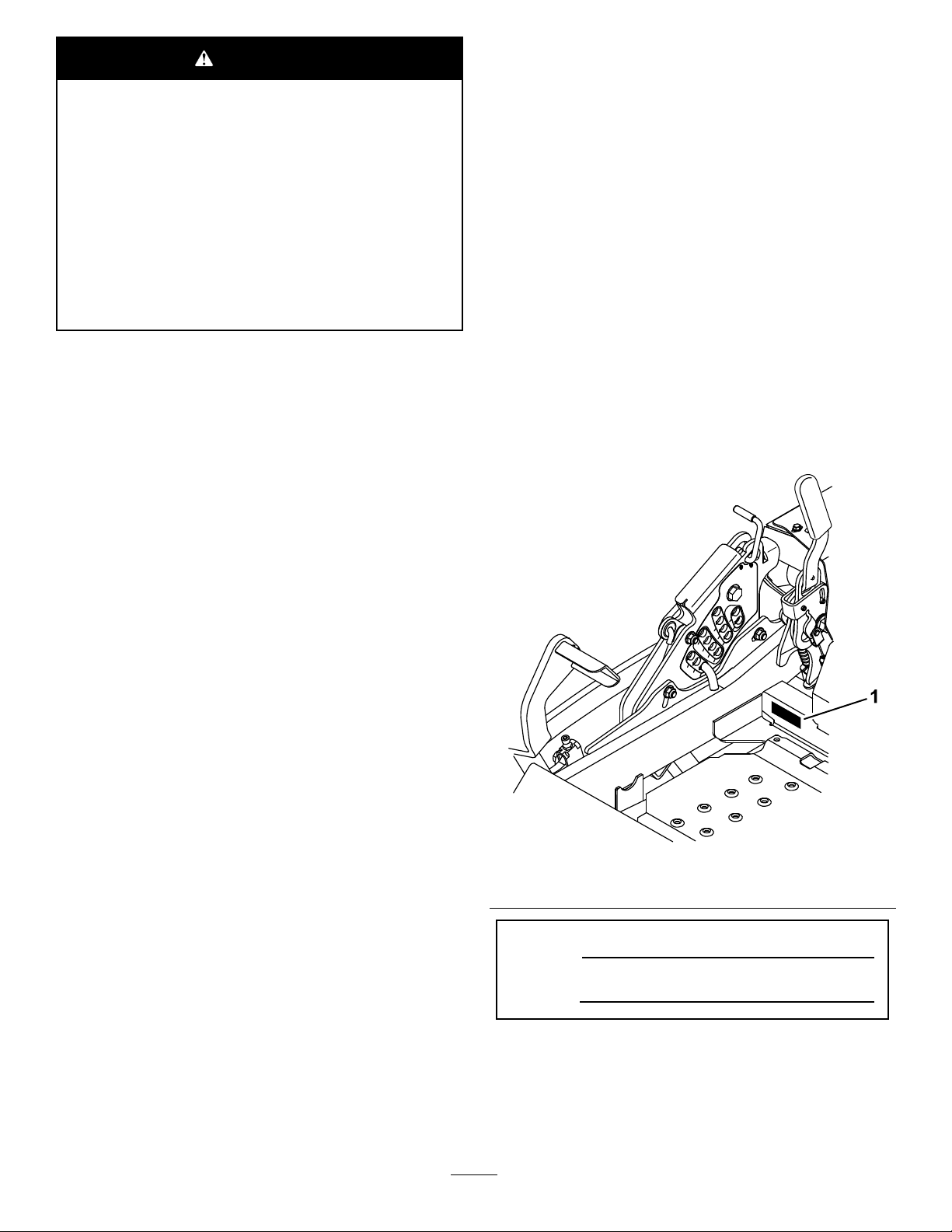
SlopeIndicator
G011841
Figure3
Thispagemaybecopiedforpersonaluse.
1.Themaximumslopeyoucansafelyoperatethemachineonis15degrees.Usetheslopecharttodeterminethedegreeofslope
ofhillsbeforeoperating.Donotoperatethismachineonaslopegreaterthan15degrees.Foldalongtheappropriateline
tomatchtherecommendedslope.
2.Alignthisedgewithaverticalsurface,atree,building,fencepole,etc.
3.Exampleofhowtocompareslopewithfoldededge.
8
Page 9

SafetyandInstructionalDecals
Safetydecalsandinstructionsareeasilyvisibletotheoperatorandarelocatednearanyareaofpotential
danger.Replaceanydecalthatisdamagedorlost.
1-403005
68-8340
98-5954
103-2076
54-9220
58-6520
1.Grease
105-7798
66-1340
9
Page 10

110-2067
110-2068
1.ReadtheOperator'sManual.
107-2102
114-4466
109-7232
1.Fast3.Neutral
2.Slow
1.Main,25A
2.PTO,10A
4.Reverse
3.Charge,25A
4.Auxiliary,15A
10
Page 11
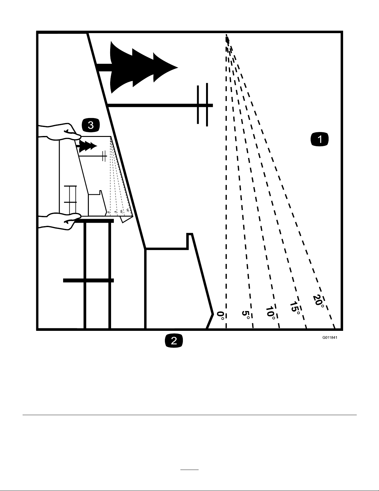
116-0205
115-7445
1.Greasepulleysandspindles
2.Maintenanceinterval—50hours
Manufacturer'sMark
1.Indicatesthebladeisidentiedasapartfromtheoriginal
machinemanufacturer.
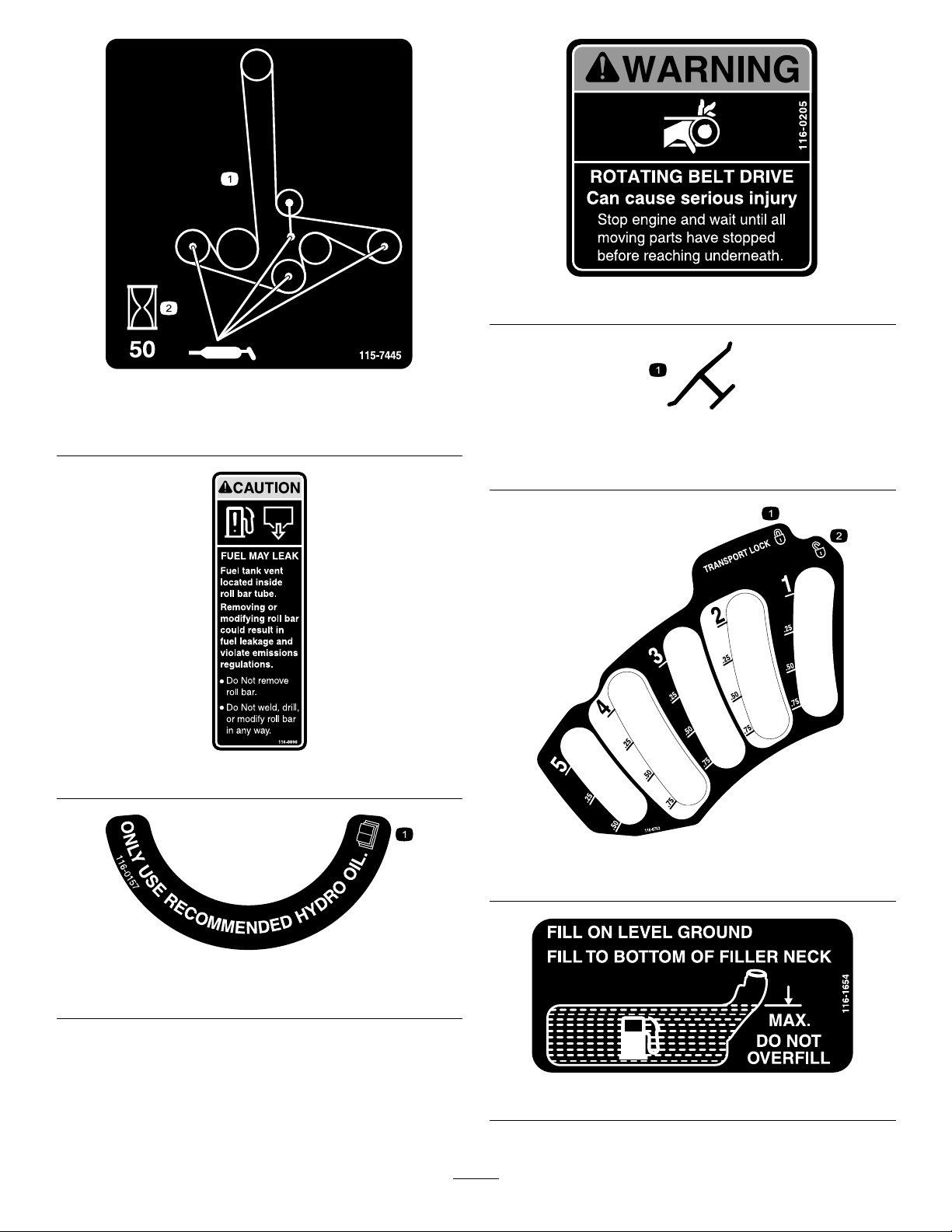
116-0090
116-0752
116-0157
1.Onlyuserecommendedhydrooil
1.Locked2.Unlocked
116-1654
11
Page 12
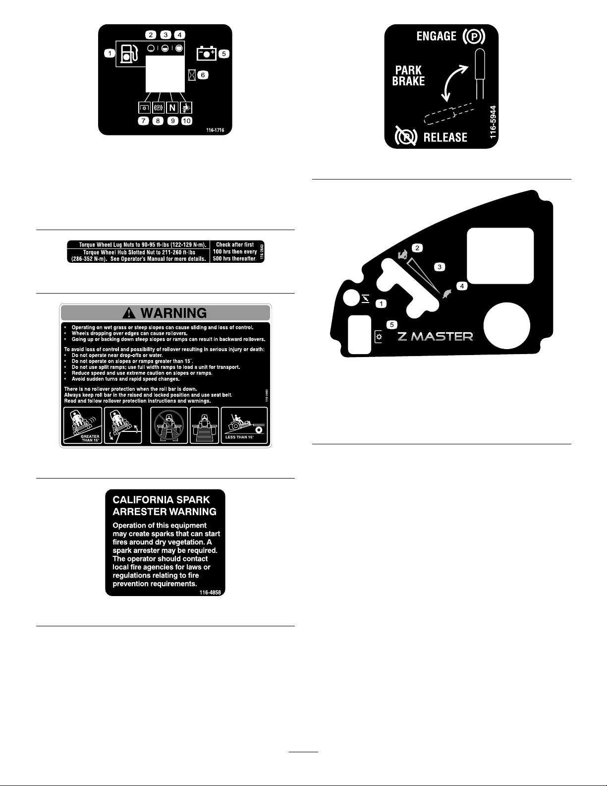
116-1716
1.Fuel6.Hourmeter
2.Empty
3.Half
4.Full9.Neutral
5.Battery
7.PTO
8.Parkingbrake
10.Operatorpresenceswitch
116-2643
116-5944
120-5897
1.Choke4.Slow
2.Fast
3.Continuousvariable
setting
5.Powertake-off(PTO),
Bladecontrolswitch
116-3303
116-4858
12
Page 13
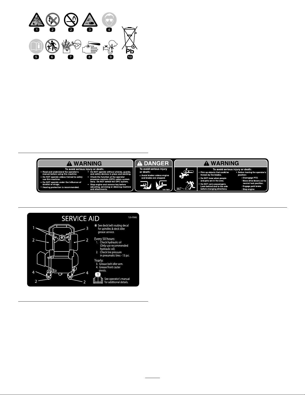
BatterySymbols
Someorallofthesesymbolsareonyourbattery
1.Explosionhazard
2.Nore,opename,or
smoking.
3.Causticliquid/chemical
burnhazard
4.Weareyeprotection9.Flusheyesimmediately
5.ReadtheOperator's
Manual.
6.Keepbystandersasafe
7.Weareyeprotection;
8.Batteryacidcancause
10.Containslead;donot
distancefromthebattery.
explosivegasescan
causeblindnessandother
injuries
blindnessorsevereburns.
withwaterandgetmedical
helpfast.
discard.
109-7069
125–9382
13
Page 14
ProductOverview
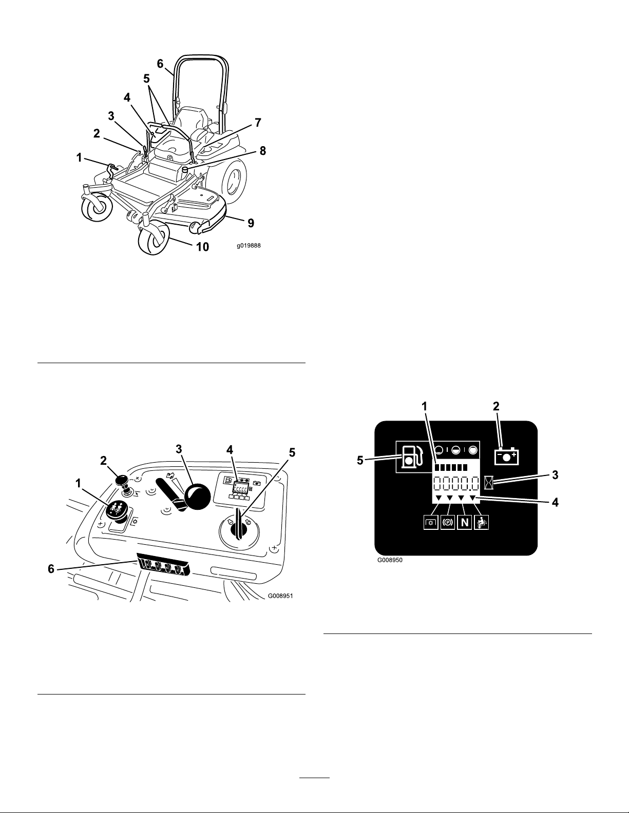
g019888
25
25
10
15
G008951
1
2
3
4
5
6
HourMeter
Thehourmeterrecordsthenumberofhourstheenginehas
operated.Itoperateswhentheengineisrunning.Usethese
timesforschedulingregularmaintenance(Figure6).
FuelGauge
Thefuelgaugeislocatedwiththehourmeter,andthebars
lightupwhentheignitionswitchisintheOnposition(Figure
6).
Theindicatorlightappearswhenthefuellevelislow
(approximatelyonegallonremaininginthefueltank).
Safety-interlockIndicators
Therearesymbolsonthehourmeter,andtheindicatewitha
blacktrianglethattheinterlockcomponentisinthecorrect
Figure4
position(Figure6).
1.Height-of-cutdeck-lift
pedal
2.Transportlock
3.Parking-brakelever8.Fuelcap
4.Controls
5.Motion-controllevers
6.Rollbar
7.Seatbelt
9.Mowerdeck
10.Casterwheel
Controls
Becomefamiliarwithallthecontrolsbeforeyoustartthe
engineandoperatethemachine(Figure4andFigure5).
Battery-indicatorLight
IftheignitionkeyisturnedtotheOnpositionforafew
seconds,thebatteryvoltagewillbedisplayedinthearea
wherethehoursarenormallydisplayed.
Thebatterylightturnsonwhentheignitionisturnedonand
whenthechargeisbelowthecorrectoperatinglevel(
6).
Figure6
Figure
1.Fuelgauge(bars)4.Safety-interlocksymbols
Figure5
1.PTOSwitch
2.Choke
3.Throttlecontrol6.Fuses
4.Hour
5.Ignitionswitch
2.Batterylight
3.Hourmeter
meter/Safety-interlock
display
ThrottleControl
ThethrottlecontrolisvariablebetweenFastandSlow.
5.Lowfuel-indicatorlight
Choke
Usethechoketostartacoldengine.Pullthechokeknobup
toengageit.
14
Page 15

Blade-controlSwitch(PTO)
Neutral-lockPosition
Theblade-controlswitch(PTO)isusedtoengagetheelectric
clutchanddrivethemowerblades.Pulltheswitchupto
Theneutral-lockpositionisusedwiththesafety-interlock
systemtoengageandtodeterminetheneutralposition.
engagethebladesandrelease.Todisengagetheblades,
pushtheblade-controlswitch(PTO)downormovea
motion-controlleverintotheneutral-lockposition.
FuelShut-offValve
Closethefuelshut-offvalve(undertheseat)when
IgnitionSwitch
Thisswitchisusedtostartthemowerengineandhas3
positions:Start,RunandOff.
transportingorstoringthemower.
Attachments/Accessories
AselectionofToroapprovedattachmentsandaccessoriesis
Motion-controlLevers
Themotion-controlleversareusedtodrivethemachine
forward,reverse,andturneitherdirection.
availableforusewiththemachinetoenhanceandexpand
itscapabilities.ContactyourAuthorizedServiceDealeror
Distributororgotowww .Toro.comforalistofallapproved
attachmentsandaccessories.
Specications
Note:Specicationsanddesignaresubjecttochangewithoutnotice.
Width:
48-inchDeck52-inchDeck60-inchDeck70-inchDeck
WithoutDeck
DeectorUp137.2cm(54inches)146cm(57.5inches)156.8cm(61.7inches)187cm(73.6inches)
DeectorDown161.4cm(63.6inches)171.8cm(67.6inches)192.2cm(75.7inches)222.4cm(87.6inches)
116.1cm(45.7inches)116.1cm(45.7inches)134.6cm(53inches)150.1cm(59.1inches)
Length:
48-inchDeck52-inchDeck60-inchDeck70-inchDeck
RollBar-Up
RollBar-Down
201.2cm(79.2inches)201.2cm(79.2inches)211.1cm(83.1inches)218.7cm(86.1inches)
205.5cm(80.9inches)205.5cm(80.9inches)215.4cm(84.8inches)223cm(87.8inches)
Height:
RollBar-UpRollBar-Down
179.1cm(70.5inches)118.9cm(46.8inches)
Weight:
ModelWeight
74922
74923
74925
74927
78922
78924
520kg(1147lbs)
547kg(1206lbs)
569kg(1254lbs)
605kg(1334lbs)
520kg(1147lbs)
520kg(1147lbs)
15
Page 16

Operation
Note:Determinetheleftandrightsidesofthemachine
fromthenormaloperatingposition.
AddingFuel
•Forbestresults,useonlyclean,fresh(lessthan30days
old),unleadedgasolinewithanoctaneratingof87or
higher((R+M)/2ratingmethod).
•Ethanol:Gasolinewithupto10%ethanol(gasohol)
or15%MTBE(methyltertiarybutylether)byvolume
isacceptable.EthanolandMTBEarenotthesame.
Gasolinewith15%ethanol(E15)byvolumeisnot
approvedforuse.Neverusegasolinethatcontains
morethan10%ethanolbyvolume,suchasE15
(contains15%ethanol),E20(contains20%ethanol),or
E85(containsupto85%ethanol).Usingunapproved
gasolinemaycauseperformanceproblemsand/orengine
damagewhichmaynotbecoveredunderwarranty.
•Donotusegasolinecontainingmethanol.
•Donotstorefueleitherinthefueltankorfuelcontainers
overthewinterunlessafuelstabilizerisused.
•Donotaddoiltogasoline.
DANGER
Incertainconditionsduringfueling,static
electricitycanbereleasedcausingasparkwhich
canignitethegasolinevapors.Areorexplosion
fromgasolinecanburnyouandothersandcan
damageproperty.
•Alwaysplacegasolinecontainersontheground
awayfromyourvehiclebeforelling.
•Donotllgasolinecontainersinsideavehicleor
onatruckortrailerbedbecauseinteriorcarpets
orplastictruckbedlinersmayinsulatethe
containerandslowthelossofanystaticcharge.
•Whenpractical,removegas-poweredequipment
fromthetruckortrailerandrefueltheequipment
withitswheelsontheground.
•Ifthisisnotpossible,thenrefuelsuch
equipmentonatruckortrailerfromaportable
container,ratherthanfromagasolinedispenser
nozzle.
•Ifagasolinedispensernozzlemustbeused,
keepthenozzleincontactwiththerimofthe
fueltankorcontaineropeningatalltimesuntil
fuelingiscomplete.
DANGER
Incertainconditions,gasolineisextremely
ammableandhighlyexplosive.Areorexplosion
fromgasolinecanburnyouandothersandcan
damageproperty.
•Fillthefueltankoutdoors,inanopenarea,
whentheengineiscold.Wipeupanygasoline
thatspills.
•Neverllthefueltankinsideanenclosedtrailer.
•Donotllthefueltankcompletelyfull.Add
gasolinetothefueltankuntilthelevelis6to13
mm(1/4to1/2inch)belowthebottomofthe
llerneck.Thisemptyspaceinthetankallows
gasolinetoexpand.
•Neversmokewhenhandlinggasoline,andstay
awayfromanopenameorwheregasoline
fumesmaybeignitedbyaspark.
•Storegasolineinanapprovedcontainerand
keepitoutofthereachofchildren.Neverbuy
morethana30-daysupplyofgasoline.
•Donotoperatewithoutentireexhaustsystemin
placeandinproperworkingcondition.
WARNING
Gasolineisharmfulorfatalifswallowed.Long-term
exposuretovaporscancauseseriousinjuryand
illness.
•Avoidprolongedbreathingofvapors.
•Keepfaceawayfromnozzleandgastankor
conditionerbottleopening.
•Avoidcontactwithskin;washoffspillagewith
soapandwater.
UsingStabilizer/Conditioner
Useafuelstabilizer/conditionerinthemachinetoprovide
thefollowingbenets:
•Keepsgasolinefreshduringstorageof90daysorless.
Forlongerstorageitisrecommendedthatthefueltank
bedrained.
•Cleanstheenginewhileitruns
•Eliminatesgum-likevarnishbuildupinthefuelsystem,
whichcauseshardstarting
Important:Donotusefueladditivescontaining
methanolorethanol.
Addthecorrectamountofgasstabilizer/conditionerto
thegas.
Note:Afuelstabilizer/conditionerismosteffective
whenmixedwithfreshgasoline.T ominimizethechance
16
Page 17
ofvarnishdepositsinthefuelsystem,usefuelstabilizer
G008942
1
2
4
3
atalltimes.
UsingtheRolloverProtection System(ROPS)
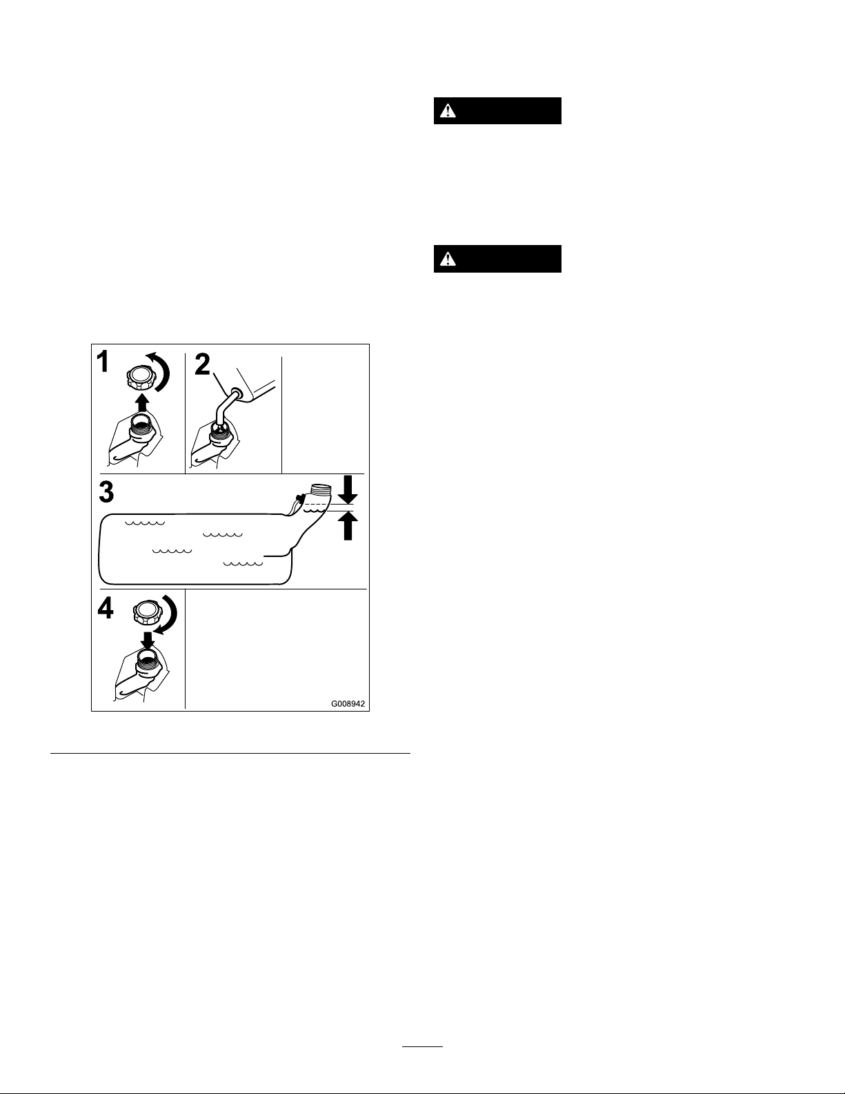
FillingtheFuelTank
Note:Donotllthefueltankcompletelyfull.Fillthefuel
tanktothebottomofthellerneck.Theemptyspaceinthe
tankallowsthegasolinetoexpand.
1.Parkthemachineonlevelground.
2.Shuttheengineoffandsettheparkingbrake.
3.Cleanaroundthefuel-tankcap.
4.Fillthefueltanktothebottomofthellerneck(
7).
Note:Ensurethatthereisemptyspaceinthetankto
allowthegasolinetoexpand
WARNING
Toavoidinjuryordeathfromrollover:keeptheroll
barinthefullyraisedlockedpositionandusethe
seatbelt.
Ensuretheseatissecuredtothemachine.
Figure
WARNING
Thereisnorolloverprotectionwhentherollbaris
inthedownposition.
•Lowertherollbaronlywhenabsolutely
necessary.
•Donotweartheseatbeltwhentherollbaris
inthedownposition.
•Driveslowlyandcarefully.
•Raisetherollbarassoonasclearancepermits.
•Checkcarefullyforoverheadclearances(i.e.
branches,doorways,electricalwires)before
drivingunderanyobjectsanddonotcontact
them.
Figure7
CheckingtheEngine-oilLevel
Beforeyoustarttheengineandusethemachine,checktheoil
levelintheenginecrankcase;refertoCheckingtheEngine-oil
Level(page36).
BreakingInaNewMachine
Newenginestaketimetodevelopfullpower.Mowerdecks
anddrivesystemshavehigherfrictionwhennew ,placing
additionalloadontheengine.Allow40to50hoursof
break-intimefornewmachinestodevelopfullpowerand
bestperformance.
Important:Lowertherollbaronlywhenabsolutely
necessary.
Important:Ensuretheseatissecuredtothemachine.
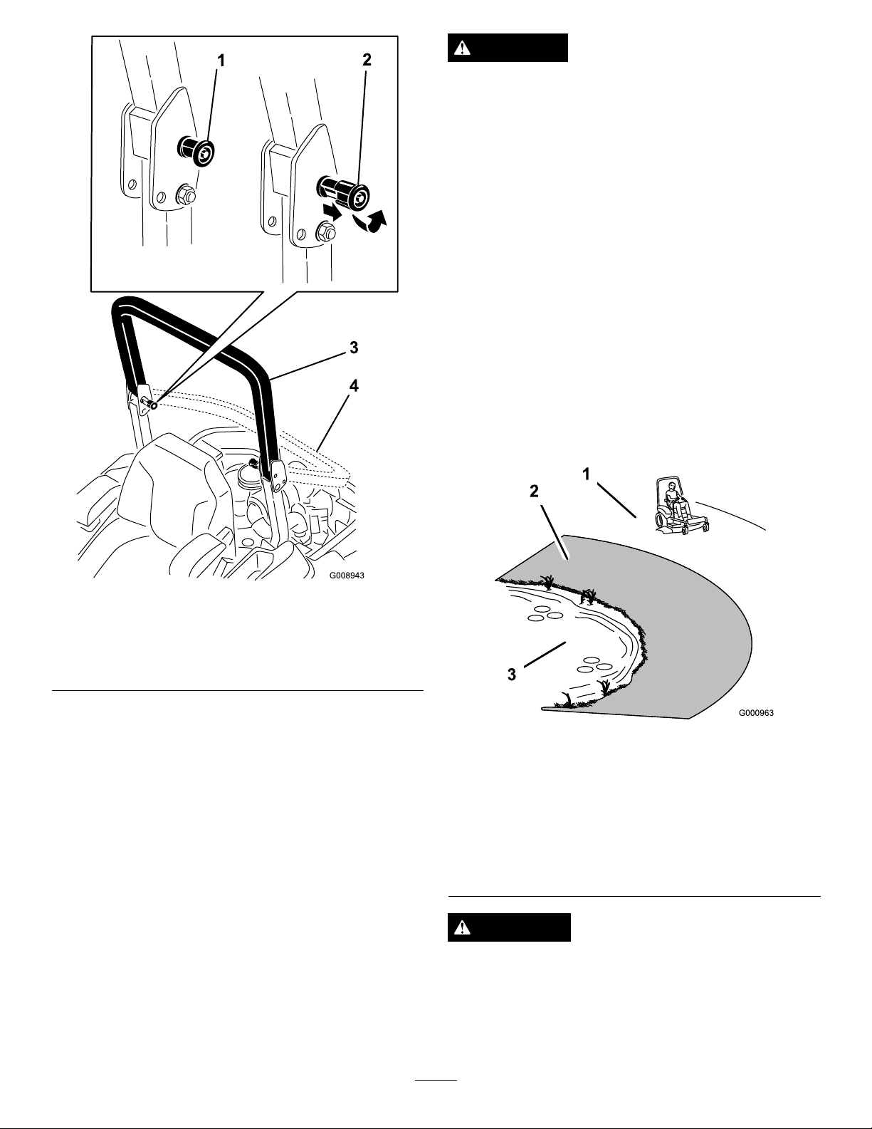
1.Tolowertherollbar,applyforwardpressuretothe
upperpartoftherollbar.
2.Pullbothknobsoutandrotatethem90°sotheyare
notengaged(Figure8).
3.Lowertherollbartothedownposition(Figure8).
17
Page 18
DANGER
Operatingonwetgrassorsteepslopescancause
slidingandlossofcontrol.
Wheelsdroppingoveredgescancauserollovers,
whichmayresultinseriousinjury,deathor
drowning.
Thereisnorolloverprotectionwhentherollbaris
down.
Alwayskeeptherollbarintheraisedandlocked
positionandusetheseatbelt.
Readandfollowtherolloverprotectioninstructions
andwarnings.
Toavoidlossofcontrolandpossibilityofrollover:
•Donotoperateneardrop-offsornearwater.
•Donotoperateonslopesgreaterthan15degrees.
•Reducespeedanduseextremecautionon
slopes.
•Avoidsuddenturnsorrapidspeedchanges.
Figure8
1.ROPSknob
2.PullROPSknoboutand
rotate90degrees
3.Rollbarintheupright
position
4.Rollbarinthefolded
position
4.Toraisetherollbar,raisetherollbartotheoperate
position,rotatetheknobssothattheymovepartially
intothegrooves(Figure8).
5.Raisetherollbartothefulluprightpositionwhile
pushingontheupperrollbarandthepinswillsnapinto
positionwhentheholesalignwiththepins(Figure8).
Important:Alwaysusetheseatbeltwiththeroll
barintheraisedposition.
6.Pushontherollbarandensurethatbothpinsare
engaged.
ThinkSafetyFirst
Pleasereadallsafetyinstructionsandsymbolsinthesafety
section.Knowingthisinformationcouldhelpyouor
bystandersavoidinjury.
Figure9
1.SafeZone—usethe
ZMasterhereonslopes
lessthan15degreesor
atareas.
2.DangerZone—usea
walk-behindmowerand/or
ahandtrimmeronslopes
greaterthan15degrees,
neardrop-offsandwater.
3.Water
CAUTION
Thismachineproducessoundlevelsinexcessof
85dBAattheoperatorsearandcancausehearing
lossthroughextendedperiodsofexposure.
Wearhearingprotectionwhenoperatingthis
machine.
18
Page 19
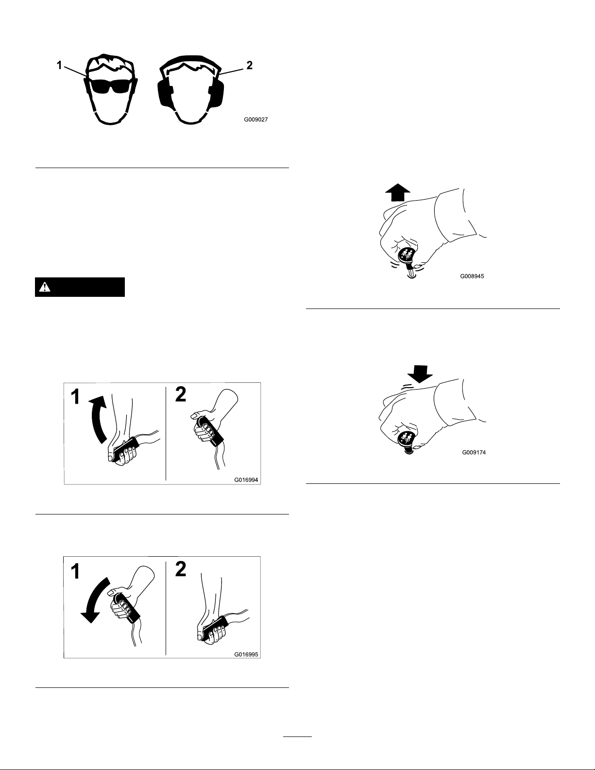
Theuseofprotectiveequipmentforeyes,ears,feet,andhead
G009027
1
2
G016994
1
2
G016995
1
2
G008945
G009174
isrecommended.
Figure10
1.Wearsafetyglasses
2.Wearhearingprotection
OperatingtheParkingBrake
Alwayssettheparkingbrakewhenyoustopthemachineor
leaveitunattended.
SettingtheParkingBrake
OperatingtheMower Blade-controlSwitch(PTO)
Theblade-controlswitch(PTO)startsandstopsthemower
bladesandanypoweredattachments.
EngagingtheBlade-controlSwitch
(PTO)
Note:Engagingtheblade-controlswitch(PTO)withthe
throttlepositionathalforlesswillcauseexcessivewearto
thedrivebelts.
WARNING
Parkingbrakemaynotholdmachineparkedona
slopeandcouldcausepersonalinjuryorproperty
damage.
Donotparkonslopesunlesswheelsarechocked
orblocked
Figure11
ReleasingtheParkingBrake
Figure13
DisengagingtheBlade-controlSwitch
(PTO)
Figure14
Figure12
19
Page 20
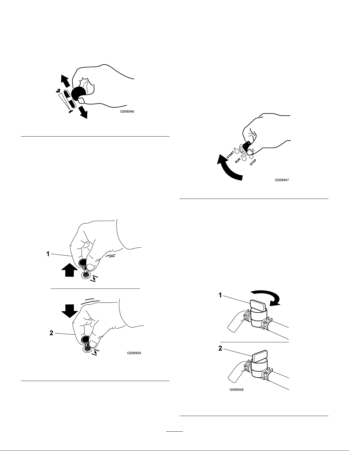
OperatingtheThrottle
G008946
G008959
1
2
START
RUN
STOP
G008947
G008948
1
2
OperatingtheIgnitionSwitch
ThethrottlecontrolcanbemovedbetweenFastandSlow
positions(Figure15).
AlwaysusetheFastpositionwhenturningonthemower
deckwiththeblade-controlswitch(PTO).
Figure15
OperatingtheChoke
Usethechoketostartacoldengine.
1.Iftheengineiscold,usethechoketostarttheengine.
2.Pulluponthechokeknobtoengagethechokebefore
usingtheignitionswitch(Figure16).
1.TurntheignitionkeytotheStartposition(Figure17).
Note:Whentheenginesstarts,releasethekey.
Important:Donotengagestarterformorethan5
secondsatatime.Iftheenginefailstostartallow
a15secondcool-downperiodbetweenattempts.
Failuretofollowtheseinstructionscanburnout
thestartermotor.
Note:Additionalstartingcyclesmayberequired
whenstartingtheengineforthersttimeafterthefuel
systemhasbeenwithoutfuelcompletely.
Figure17
3.Pushdownonthechoketodisengagethechokeafter
theenginehasstarted(
Figure16).
2.Turntheignitionkeytostoptostoptheengine.
UsingtheFuelShutoffValve
Thefuelshut-offvalveislocatedundertheseat.Movethe
seatforwardtoaccessit.
Closethefuelshut-offvalvefortransport,maintenance,and
storage.
Ensurethefuelshut-offvalveisopenwhenstartingthe
engine.
Figure16
1.Onposition2.Offposition
Figure18
1.Onposition2.Offposition
20
Page 21
StartingandStoppingthe
g017006
START
RUN
STOP
G008947
g017007
Engine
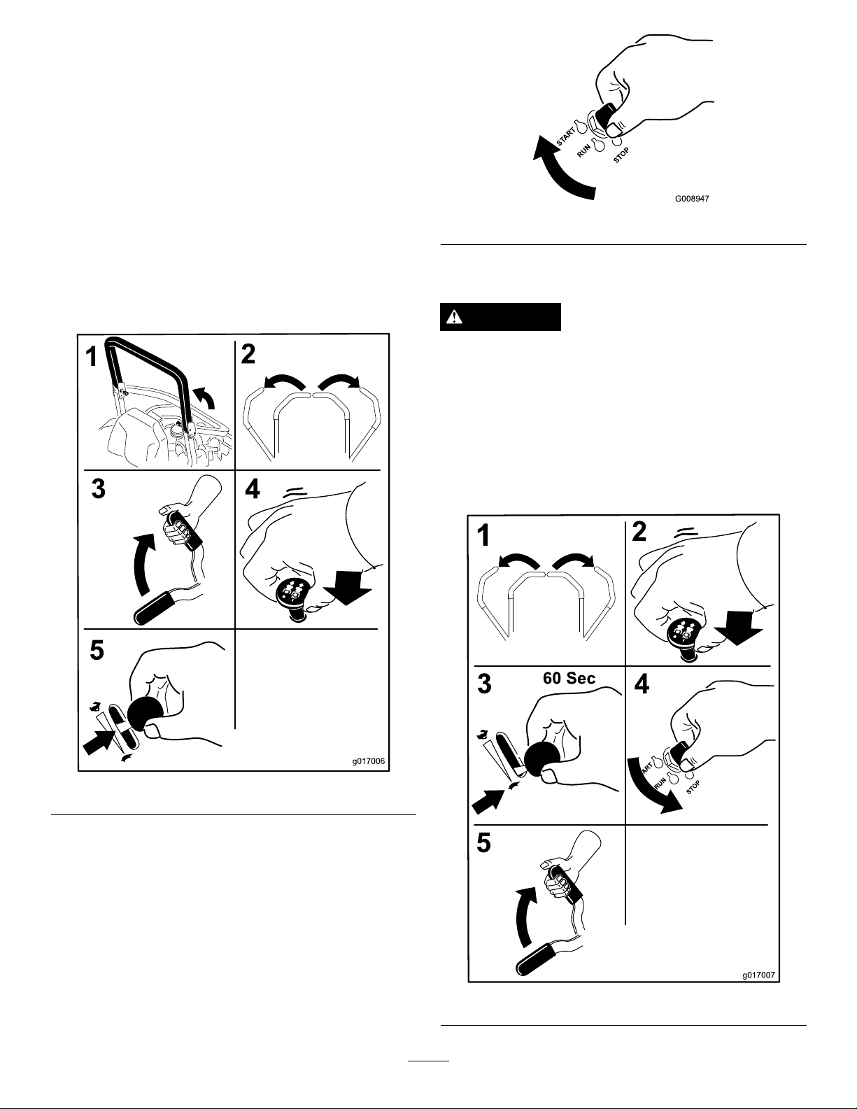
StartingtheEngine
1.RaisetheROPSupandlockintoplace,sitontheseat,
andfastentheseatbelt.
2.Movethemotioncontrolstoneutral-lockedposition.
3.Settheparkingbrake;refertoSettingtheParking
Brake(page19).
4.Movetheblade-controlswitch(PTO)totheOff
position(Figure19).
5.MovethethrottlelevermidwaybetweentheSlowand
Fastpositions.
Figure20
StoppingtheEngine
CAUTION
Childrenorbystandersmaybeinjuredifthey
moveorattempttooperatethemachinewhileitis
unattended.
Alwaysremovetheignitionkeyandsettheparking
brakewhenleavingthemachineunattended,even
ifjustforafewminutes.
Lettheengineidleatslowthrottle(turtle)for60seconds
beforeturningtheignitionswitchoff.
Figure19
6.TurntheignitionkeytotheStartposition(Figure20).
Note:Whentheenginesstarts,releasethekey.
Important:Donotengagestarterformorethan5
secondsatatime.Iftheenginefailstostartallow
a15-secondcool-downperiodbetweenattempts.
Failuretofollowtheseinstructionscanburnout
thestartermotor.
Note:Additionalstartingcyclesmayberequired
whenstartingtheengineforthersttimeafterthefuel
systemhasbeenwithoutfuelcompletely.
Figure21
21
Page 22

Important:Makesurethatthefuelshut-offvalveis
G009181
1
closedbeforetransportingorstoringthemachine,as
fuelleakagemayoccur.Settheparkingbrakebefore
transporting.Makesuretoremovethekeyasthefuel
pumpmayrunandcausethebatterytolosecharge.
UsingtheSafety-interlock System
CAUTION
Ifsafety-interlockswitchesaredisconnectedor
damagedthemachinecouldoperateunexpectedly
causingpersonalinjury.
•Donottamperwiththeinterlockswitches.
•Checktheoperationoftheinterlockswitches
dailyandreplaceanydamagedswitchesbefore
operatingthemachine.
UnderstandingtheSafety-interlock
System
Thesafety-interlocksystemisdesignedtopreventtheengine
fromstartingunless:
•Theparkingbrakeisengaged.
•Theblade-controlswitch(PTO)isdisengaged.
•Themotion-controlleversareintheneutral-locked
position.
Thesafety-interlocksystemalsoisdesignedtostopthe
enginewhenthetractioncontrolsaremovedfromthelocked
positionwiththeparkingbrakeengagedorifyourisefrom
theseatwhenthePTOisengaged.
TestingtheSafety-interlockSystem
ServiceInterval:Beforeeachuseordaily
Testthesafety-interlocksystembeforeyouusethemachine
eachtime.Ifthesafetysystemdoesnotoperateasdescribed
below,haveanAuthorizedServiceDealerrepairthesafety
systemimmediately .
1.Sittingontheseat,engagetheparkingbrakeandmove
theblade-controlswitch(PTO)totheOnposition.
Trystartingtheengine;theengineshouldnotcrank.
2.Sittingontheseat,engagetheparkingbrakeandmove
theblade-controlswitch(PTO)totheOffposition.
Moveeithermotion-controllever(outofneutrallocked
position).Trystartingtheengine;theengineshould
notcrank.Repeatforothercontrollever.
3.Sittingontheseat,engagetheparkingbrake,move
theblade-controlswitch(PTO)totheOffposition,
andmovethemotion-controlleverstoneutral-lock
position.Nowstarttheengine.Whiletheengine
isrunning,releasetheparkingbrake,engagethe
blade-controlswitch(PTO)andriseslightlyfromthe
seat;theengineshouldstop.
4.Sittingontheseat,engagetheparkingbrake,move
theblade-controlswitch(PTO)totheOffposition,
andmovethemotion-controlleverstoneutral-lock
position.Nowstarttheengine.Whiletheengine
isrunning,centereithermotioncontrolandmove
(forwardorreverse);theengineshouldstop.Repeat
forothermotioncontrol.
5.Sittingontheseat,disengagetheparkingbrake,move
theblade-controlswitch(PTO)totheOffposition,
andmovethemotion-controlleverstoneutral-lock
position.Trystartingtheengine;theengineshould
notcrank.
Thehourmeterhassymbolstonotifytheuserwhenthe
interlockcomponentisinthecorrectposition.Whenthe
componentisinthecorrectposition,atrianglewilllightup
inthecorrespondingsquare.
Figure22
1.Triangleslightupwhentheinterlockcomponentsareinthe
correctposition
DrivingForwardorBackward
Thethrottlecontrolregulatestheenginespeedasmeasured
inrpm(revolutionsperminute).Placethethrottlecontrolin
theFastpositionforbestperformance.Alwaysoperateinthe
fullthrottlepositionwhenmowing.
CAUTION
Machinecanspinveryrapidly.Operatormaylose
controlofmachineandcausepersonalinjuryor
damagetomachine.
•Usecautionwhenmakingturns.
•Slowthemachinedownbeforemakingsharp
turns.
22
Page 23

UsingtheMotion-controlLevers
G008952
G008953
Figure24
Figure23
1.Motion-control
lever—neutral-lock
position
2.Center,unlockedposition5.Frontofmachine
3.Forward
4.Backward
DrivingForward
Note:Theenginewillkillifthetraction-controlleversare
movedwiththeparkingbrakeengaged.
Tostop,pullthemotion-controlleverstotheneutralposition.
1.Releasetheparkingbrake;refertoReleasingthe
ParkingBrake(page19)
2.Movetheleverstothecenter,unlockedposition.
3.Togoforward,slowlypushthemotion-controllevers
forward(Figure24).
.
DrivingBackward
1.Movetheleverstothecenter,unlockedposition.
2.Togobackward,slowlypullthemotion-controllevers
rearward(
Figure25).
Figure25
23
Page 24

StoppingtheMachine
Tostopthemachine,movethetraction-controlleversto
neutral,andthenmovethemtothelockedposition,disengage
thepowertakeoff(blade-controlswitch(PTO),andturnthe
ignitionkeytotheOffposition.
Settheparkingbrakewhenyouleavethemachine;referto
SettingtheParkingBrake(page19).Remembertoremove
thekeyfromtheignitionswitch.
CAUTION
Childrenorbystandersmaybeinjuredifthey
moveorattempttooperatethemachinewhileitis
unattended.
Alwaysremovetheignitionkeyandsettheparking
brakewhenleavingthemachineunattended,even
ifjustforafewminutes.
AdjustingtheHeight-of-Cut
UsingtheTransportLock
Thetransportlockhas2positions,andisusedwiththe
deck-liftpedal.Thereisalockpositionandaunlockposition
forthetransportposition.Thetransportlockisusedwith
thedeck-liftpedal(Figure26).
Figure26
Transport-LockPositions
1.Transportlock3.Unlockposition—doesnot
2.Lockposition—mower
deckwilllockintotransport
position
24
lockthemowerdeckinto
transportposition
Page 25

AdjustingtheHeight-of-CutPin
1
3
2
G017027
Theheight-of-cutisadjustedfrom25to140mm(1to
5-1/2inches)in6mm(1/4inch)incrementsbyrelocating
theclevispinintodifferentholelocations.
1.Movethetransportlocktothelockposition.
2.Pushonthedeck-liftpedalwithyourfoot,andraisethe
mowerdecktothetransportposition(alsothe140mm
(5-1/2inches)cuttingheightposition)asshownin
Figure27.
3.Toadjust,rotatethepin90degreesandremovethepin
fromtheheight-of-cutbracket(Figure27).
4.Selectaholeintheheight-of-cutbracketcorresponding
totheheight-of-cutdesired,andinsertthepin(
27).
5.Pushonthedecklift,pullbackonthetransportlock,
andslowlylowerthemowerdeck.
Figure28
Figure
1.Anti-scalproller4.Flangenut
2.Spacer
3.Bushing
5.Bolt
Figure27
1.Deck-liftpedal
2.Cut-of-heightpin
AdjustingtheAnti-scalp Rollers
Wheneveryouchangetheheight-of-cut,itisrecommended
toadjusttheheightoftheanti-scalprollers.
1.Disengagetheblade-controlswitch(PTO),movethe
motion-controlleverstotheneutral-lockedposition,
andsettheparkingbrake.
2.Stoptheengine,removethekey,andwaitforallmoving
partstostopbeforeleavingtheoperatingposition.
3.Transportlock
Figure29
1.Anti-scalproller3.Flangenut
2.Bushing4.Bolt
Figure30
1.Anti-scalproller4.Flangenut
2.Spacer
3.Bushing
5.Bolt
3.Adjusttheanti-scalprollersasshownin
,,and.
25
Page 26

AdjustingtheFlowBafeCam
G008961
1
2
3
4
Locks
Thisprocedureisapplicableonlytomachineswiththe
ow-bafelocks.Certainmodelswillhavenutsandboltsin
placeoftheow-bafelocksandcanbeadjustedthesame.
Themower-dischargeowcanbeadjustedfordifferenttypes
ofmowingconditions.Positionthecamlocksandbafeto
givethebestqualityofcut.
1.Disengagetheblade-controlswitch(PTO),movethe
motion-controlleverstotheneutral-lockedposition,
andsettheparkingbrake.
2.Stoptheengine,removethekey,andwaitforallmoving
partstostopbeforeleavingtheoperatingposition.
3.Toadjustthecamlocks,swingtheleveruptoloosen
thecamlock(Figure31).
PositionA
Thisisthefullrearposition.Thesuggesteduseforthis
positionisafollows:
•Short,lightgrassmowingconditions
•Dryconditions
•Smallergrassclippings
•Propelsgrassclippingsfartherawayfromthemower
4.Adjustthebafeandcamlocksintheslotstothe
desireddischargeow.
5.Swingtheleverbackovertotightenthebafeandcam
Figure31).
locks(
6.Ifthecamlocksdonotlockthebafeintoplaceoritis
tootight,loosentheleverandthenrotatethecamlock.
Note:Adjustthecamlockuntilthedesiredlocking
pressureisachieved.
Figure31
1.Unlocklever
2.Rotatethecamlockto
increaseordecrease
lockingpressure
3.Positionthebafe
4.Locklever
Figure32
PositionB
Usethispositionwhenbagging.Alwaysalignitwiththe
bloweropening.
Figure33
PositionC
PositioningtheFlowBafe
Thefollowingguresareonlyrecommendationsforuse.
Adjustmentswillvarybygrasstype,moisturecontent,and
theheightofthegrass.
Note:Iftheenginepowerdrawsdownandthemower
groundspeedisthesame,openupthebafe.
Thisisthefullopenposition.Thesuggesteduseforthis
positionisasfollows:
•Tall,densegrassmowingconditions
•Wetconditions
•Lowerstheengine-powerconsumption
•Allowsincreasedgroundspeedinheavyconditions
•ThispositionissimilartothebenetsoftheToroSFS
mower
26
Page 27

Figure34
g019754
g019755
g019768
1
ChangingtheSeatSuspension
Theseatadjuststoprovideasmoothandcomfortableride.
Positiontheseatwhereyouaremostcomfortable.
Toadjust,turntheknobinfronteitherdirectiontoprovide
thebestcomfort(Figure37).
PositioningtheSeat
Theseatmovesforwardandbackward.Positiontheseat
whereyouhavethebestcontrolofthemachineandaremost
comfortable.
Toadjust,movetheleversidewaystounlocktheseat(
35).
Figure35
UnlatchingtheSeat
Figure37
1.Seat-suspensionknob
Figure
UsingtheDrive-wheel-release Valves
WARNING
Handsmaybecomeentangledintherotatingdrive
componentsbelowtheenginedeck,whichcould
resultinseriousinjury.
Stoptheengine,removethekey ,andallow
allmovingpartstostopbeforeaccessingthe
drive-wheel-releasevalves.
WARNING
Theengineandhydraulic-driveunitscanbecome
veryhot.Touchingahotengineorhydraulic-drive
unitscancausesevereburns.
Figure36
1.Seatlatch2.Seat
Allowtheengineandhydraulic-driveunitstocool
completelybeforeaccessingthedrive-wheel-release
valves.
Thedrive-wheel-releasevalvesarelocatedinthebackofeach
hydraulic-driveunit,undertheseat.
Note:Makesurethereleasevalvesareinthefullyhorizontal
positionwhenoperatingthemachineorseveredamagetothe
hydraulicsystemcanoccur.
1.DisengagethePTO(blade-controlswitch)andturn
theignitionkeytotheOffposition,movetheleversto
neutral-lockedposition,applytheparkingbrake,and
removethekey.
27
Page 28

2.Rotatetherelease-valveleversverticallytopushthe
machine(Figure38).
Note:Thisallowshydraulicoiltobypassthepump
enablingthewheelstoturn.
UsingtheSideDischarge
Themowerhasahingedgrassdeectorthatdisperses
clippingstothesideanddowntowardtheturf.
3.Disengagetheparkingbrakebeforepushingthe
machine.
Figure38
1.Verticaltopushthe
machine
2.Horizontaltorunthe
machine
DANGER
Withoutagrassdeector,dischargecover,ora
completegrass-catcherassemblymountedin
place,youandothersareexposedtobladecontact
andthrowndebris.Contactwithrotatingmower
blade(s)andthrowndebriswillcauseinjuryor
death.
•Neverremovethegrassdeectorfromthemower
becausethegrassdeectorroutesmaterialdown
towardtheturf.Ifthegrassdeectorisever
damaged,replaceitimmediately.
•Neverputyourhandsorfeetunderthemower.
•Nevertrytoclearthedischargeareaormower
bladesunlessyoumovethepowertakeoff
(blade-controlswitch(PTO)totheOffposition,
rotatetheignitionkeytotheOffposition,and
removethekey.
•Makesurethegrassdeectorisinthedown
position.
4.Rotatetherelease-valvelevershorizontallytorunthe
machine(Figure38).
28
Page 29

TransportingMachines
LoadingMachines
Useaheavy-dutytrailerortrucktotransportthemachine.
Ensurethatthetrailerortruckhasallthenecessarybrakes,
lighting,andmarkingasrequiredbylaw .Pleasecarefullyread
allthesafetyinstructions.Knowingthisinformationcould
helpyou,yourfamily,petsorbystandersavoidinjury.
WARNING
Drivingonthestreetorroadwaywithoutturn
signals,lights,reectivemarkings,oraslow
movingvehicleemblemisdangerousandcanlead
toaccidentscausingpersonalinjury.
Donotdrivemachineonapublicstreetorroadway.
Totransportthemachine:
1.Ifusingatrailer,connectittothetowingvehicle,and
connectthesafetychains.
2.Ifapplicable,connectthetrailerbrakes.
3.Loadthemachineontothetrailerortruck.
4.Stoptheengine,removethekey,setthebrake,and
closethefuelvalve.
5.Usethemetaltie-downloopsonthemachineto
securelyfastenthemachinetothetrailerortruckwith
straps,chains,cable,orropes(
Figure39).
Useextremecautionwhenloadingunitsontrailersortrucks.
Onefull-widthrampthatiswideenoughtoextendbeyond
thereartiresisrecommendedinsteadofindividualrampsfor
eachsideoftheunit(Figure40).Thelower,rearsectionof
themachineframeextendsbackbetweentherearwheels,and
servesasastopfortippingbackward.Havingafull-width
rampprovidesasurfacefortheframememberstocontactif
theunitstartstotipbackward.Ifitisnotpossibletouseone
full-widthramp,useenoughindividualrampstosimulatea
full-widthcontinuousramp.
Therampshouldbelongenoughsothattheanglesdonot
exceed15degrees(
mowercomponentstogetcaughtastheunitmovesfrom
ramptotrailerortruck.Steeperanglesmayalsocausethe
unittotipbackward.Ifloadingonornearaslope,position
thetrailerortrucksoitisonthedownsideoftheslopeand
therampextendsuptheslope.Thiswillminimizetheramp
angle.Thetrailerortruckshouldbeaslevelaspossible.
Important:Donotattempttoturntheunitwhileonthe
ramp;youmaylosecontrolanddriveofftheside.
Avoidsuddenaccelerationwhendrivinguparampand
suddendecelerationwhenbackingdownaramp.Both
maneuverscancausetheunittotipbackward.
Figure40).Asteeperanglemaycause
WARNING
Loadingaunitontoatrailerortruckincreasesthe
possibilityofbackwardtip-overandcouldcause
seriousinjuryordeath.
1.Tractionunittie-downloops
Figure39
•Useextremecautionwhenoperatingauniton
aramp.
•EnsuretheROPSisintheuppositionwhile
usingtheseatbeltwhenloadingthemachine.
EnsuretheROPSwillclearthetopofan
enclosedtrailer.
•Useonlyasingle,full-widthramp;donotuse
individualrampsforeachsideoftheunit.
•Ifindividualrampsmustbeused,useenough
rampstocreateanunbrokenrampsurfacewider
thantheunit.
•Donotexceeda15-degreeanglebetweenramp
andgroundorbetweentherampandtraileror
truck.
•Avoidsuddenaccelerationwhiledrivingunitup
aramptoavoidtippingbackward.
•Avoidsuddendecelerationwhilebackingunit
downaramptoavoidtippingbackward.
29
Page 30

Figure40
1.Trailer3.Notgreaterthan
2.Full-widthramp4.Full-widthramp—side
15degrees
view
30
Page 31

OperatingTips
UsingtheFastThrottleSetting
Forbestmowingandmaximumaircirculation,operate
theengineattheFastthrottleposition.Airisrequiredto
thoroughlycutgrassclippings,sodonotsettheheight-of-cut
solowastototallysurroundthemowerbyuncutgrass.
Alwaystrytohaveonesideofthemowerfreefromuncut
grass,whichallowsairtobedrawnintothemower.
CuttingaLawnfortheFirstTime
Cutgrassslightlylongerthannormaltoensurethatthe
cuttingheightofthemowerdoesnotscalpanyuneven
ground.However,thecuttingheightusedinthepastis
generallythebestonetouse.Whencuttinggrasslongerthan
sixinchestall,youmaywanttocutthelawntwicetoensure
anacceptablequalityofcut.
Cutting1/3oftheGrassBlade
CuttingLongGrass
Ifthegrassiseverallowedtogrowslightlylongerthan
normal,orifitcontainsahighdegreeofmoisture,raisethe
cuttingheighthigherthanusualandcutthegrassatthis
setting.Thencutthegrassagainusingthelower,normal
setting.
Stopping
Ifthemachine'sforwardmotionmustbestoppedwhile
mowing,aclumpofgrassclippingsmaydropontoyourlawn.
Toavoidthis,moveontoapreviouslycutareawiththeblades
engaged.
KeepingtheUndersideoftheMower
Clean
Cleanclippingsanddirtfromtheundersideofthemower
aftereachuse.Ifgrassanddirtbuildupinsidethemower,
cuttingqualitywilleventuallybecomeunsatisfactory.
Itisbesttocutonlyabout1/3ofthegrassblade.Cutting
morethanthatisnotrecommendedunlessgrassissparse,or
itislatefallwhengrassgrowsmoreslowly .
AlternatingtheMowingDirection
Alternatemowingdirectiontokeepthegrassstanding
straight.Thisalsohelpsdisperseclippingswhichenhances
decompositionandfertilization.
MowingatCorrectIntervals
Normally,moweveryfourdays.Butremember,grassgrows
atdifferentratesatdifferenttimes.Sotomaintainthesame
cuttingheight,whichisagoodpractice,mowmoreoftenin
earlyspring.Asthegrassgrowthrateslowsinmidsummer,
mowlessfrequently.Ifyoucannotmowforanextended
period,rstmowatahighcuttingheight;thenmowagain
twodayslateratalowerheightsetting.
AdjustingtheCuttingSpeed
Toimprovecutquality,useaslowergroundspeedincertain
conditions.
MaintainingtheBlade
Maintainasharpbladethroughoutthecuttingseasonbecause
asharpbladecutscleanlywithouttearingorshreddingthe
grassblades.Tearingandshreddingturnsgrassbrownat
theedges,whichslowsgrowthandincreasesthechanceof
disease.Checkthecutterbladesdailyforsharpness,andfor
anywearordamage.Filedownanynicksandsharpenthe
bladesasnecessary.Ifabladeisdamagedorworn,replaceit
immediatelywithagenuineTOROreplacementblade.
AvoidingCuttingTooLow
Ifthecuttingwidthofthemoweriswiderthanthemower
youpreviouslyused,raisethecuttingheighttoensurethat
uneventurfisnotcuttooshort.
31
Page 32

Maintenance
RecommendedMaintenanceSchedule(s)
MaintenanceService
Interval
Aftertherst8hours
Aftertherst100hours
Aftertherst250hours
Beforeeachuseordaily
Every50hours
Every100hours
MaintenanceProcedure
•Changetheengineoil.
•Checkthewheellug-nuttorque.
•Checkthewheelhubslotted-nuttorque.
•Checktheparking-brakeadjustment.
•Changethehydraulicltersandhydraulicoilwhenusinganytypeofoil.
•Checkthesafetysystem.
•Checktheengine-oillevel.
•Checktheseatbelt.
•Checktherolloverprotectionsystem(ROPS)knobs.
•Cleantheenginescreenandtheoilcooler.
•Checkandcleanthehydraulic-unitshrouds.
•Inspecttheblades.
•Cleanthemowerdeck.
•Greasethemower-deckspindlesandtheidlerarm.
•Checkthesparkarrester(ifequipped).
•Checkthetirepressure.
•Inspectthebeltsforcracksandwear.
•Checkthehydraulicoillevel.
•Lubricatethemower-deck-liftpivots.
•Changetheengineoil(moreoftenindirtyordustyconditions).
•Check,cleanandregapthesparkplug.
•Checkandcleanengine-coolingnsandshrouds.
Every200hours
Every250hours
Every500hours
Monthly
Yearly
Yearlyorbeforestorage
•Changetheengine-oillter.
•Replacetheprimaryairlter.
•Checkthesecondaryairlter.
•ChangethehydraulicltersandhydraulicoilwhenusingMobil®1oil(moreoftenin
dirtyordustyconditions).
•Replacethesecondaryairlter .
•Replacethefuellter(moreoftenindirtyordustyconditions).
•Checkthewheellug-nuttorque.
•Checkthewheelhubslotted-nuttorque.
•Adjustthecaster-pivotbearing.
•Checktheparking-brakeadjustment.
•ChangethehydraulicltersandhydraulicoilwhenusingT oro®HYPR-OIL™500
hydraulicoil(moreoftenindirtyordustyconditions).
•Checkthebatterycharge.
•Greasethepump-belt-idlerarm.
•Greasethefrontcasterpivots(moreoftenindirtyordustyconditions).
•Repackthefrontcaster-wheelbearings(moreoftenindirtyordustyconditions).
•Lubricatethecaster-wheelhubs.
•Paintchippedsurfaces.
•Checkallmaintenanceprocedureslistedabovebeforestorage.
Important:Refertoyourengineoperator'smanualforadditionalmaintenanceprocedures.
32
Page 33

CAUTION
G017028
G009029
Ifyouleavethekeyintheignitionswitch,someonecouldaccidentlystarttheengineandseriouslyinjure
youorotherbystanders.
Removethekeyfromtheignitionbeforeyoudoanymaintenance.
Lubrication
Greasemorefrequentlywhenoperatingconditionsare
extremelydustyorsandy.
GreaseType:No.2generalpurposelithiumbaseor
molybdenumbasegrease
1.Disengagethebladecontrolswitch(PTO),movethe
motion-controlleverstotheneutral-lockedposition,
andsettheparkingbrake.
2.Stoptheengine,removethekey,andwaitforallmoving
partstostopbeforeleavingtheoperatingposition.
3.Cleanthegreasettingswitharag.
Note:Makesuretoscrapeanypaintoffthefrontof
thetting(s).
4.Connectagreaseguntothetting.
5.Pumpgreaseintothettingsuntilgreasebeginsto
oozeoutofthebearings.
6.Wipeupanyexcessgrease.
AddingLightOilorSpray
GreasingtheMower
ServiceInterval:Every50hours—Greasethemower-deck
spindlesandtheidlerarm.
Yearly—Greasethepump-belt-idlerarm.
Yearly—Greasethefrontcasterpivots(moreoftenin
dirtyordustyconditions).
Yearly—Repackthefrontcaster-wheelbearings(more
oftenindirtyordustyconditions).
Important:Makesurecuttingunitspindlesarefullof
greaseweekly.
1.Disengagethebladecontrolswitch(PTO),movethe
motion-controlleverstotheneutral-lockedposition,
andsettheparkingbrake.
2.Stoptheengine,removethekey,andwaitforallmoving
partstostopbeforeleavingtheoperatingposition.
3.Greasethemowerdeckidler-pulleypivotuntilgrease
comeoutthebottom(
4.Greasethe3spindlebearingsuntilgreasecomesout
(Figure42).
Figure42).
Lubrication
ServiceInterval:Every100hours
Lubricatethedeck-liftpivots.
Figure41
Figure42
5.Greasethedrive-belt-idlerarm(Figure43).
33
Page 34

Figure43
6.Removethedustcapandadjustthecasterpivots.
Note:Keepthedustcapoffuntilgreasingisdone;
refertoAdjustingtheCaster-pivotBearing(page45).
7.Removethehexplug.
8.Threadagreasettingintothehole.
9.Pumpgreaseintothettinguntilitoozesoutaround
thetopbearing.
10.Removethegreasettinginthehole.
11.Installthehexpluganddustcap(
Figure44).
LubricatingtheCaster-wheel Hubs
ServiceInterval:Yearly
1.Stoptheengine,waitforallmovingpartstostop,
removethekey,andengagetheparkingbrake.
Figure45
1.Sealguard2.Spacernutwithwrench
ats
2.Raisethemowerforaccess.
3.Removethecasterwheelfromthecasterforks.
4.Removethesealguardsfromthewheelhub.
5.Removeoneofthespacernutsfromtheaxleassembly
inthecasterwheel.
Note:Thread-lockingadhesivehasbeenappliedto
lockthespacernutstotheaxle.
Figure44
12.Greasethecaster-wheelbearings(Figure44).
6.Removetheaxle(withtheotherspacernutstill
assembledtoit)fromthewheelassembly.
7.Pryoutsealsandinspectbearingsforwearordamage
andreplaceifnecessary.
8.Packthebearingswithageneral-purposegrease.
9.Insert1bearingand1newsealintothewheel.
Note:Thesealsmustbereplaced.
10.Iftheaxleassemblyhashadbothspacernutsremoved
(orbrokenloose),applyathread-lockingadhesiveto1
spacernut,andthreaditontotheaxlewiththewrench
atsfacingoutward.
Note:Donotthreadthespacernutalloftheway
ontotheendoftheaxle.Leaveapproximately3mm
(1/8inch)fromtheoutersurfaceofthespacernutto
theendoftheaxleinsidethenut.
11.Inserttheassemblednutandaxleintothewheelonthe
sideofthewheelwiththenewsealandbearing.
12.Withtheopenendofthewheelfacingup,llthearea
insidethewheelaroundtheaxlefullofgeneral-purpose
grease.
13.Insertthesecondbearingandnewsealintothewheel.
34
Page 35

14.Applyathread-lockingadhesivetothesecondspacer
nut,andthreaditontotheaxlewiththewrenchats
facingoutward.
15.Torquethenutto8to9N-m(75to80in-lb),loosen,
thentorqueto2to3N-m(20to25in-lb).
Note:Makesureaxledoesnotextendbeyondeither
nut.
16.Installthesealguardsoverthewheelhub,andinsert
wheelintothecasterfork.
EngineMaintenance
WARNING
Contactwithhotsurfacesmaycausepersonal
injury.
Keephands,feet,face,clothing,andotherbody
partsawaythemuferandotherhotsurfaces.
17.Installthecasterboltandtightenthenutfully .
Important:Topreventsealandbearingdamage,check
thebearingadjustmentoften.Spinthecastertire.The
tireshouldnotspinfreely(morethan1or2revolutions)
orhaveanysideplay.Ifthewheelspinsfreely,adjustthe
torqueonthespacernutuntilthereisaslightamountof
drag.Applyanotherlayerofthread-lockingadhesive.
ServicingtheAirCleaner
ServiceInterval:Every250hours—Replacetheprimaryair
lter.
Every250hours—Checkthesecondaryairlter.
Every500hours—Replacethesecondaryairlter.
Note:Servicetheaircleanermorefrequentlyifoperating
conditionsareextremelydustyorsandy.
RemovingtheFilters
1.DisengagethePTO,movethemotion-controlleversto
theneutral-lockedposition,andsettheparkingbrake.
2.Stoptheengine,removethekey,andwaitforallmoving
partstostopbeforeleavingtheoperatingposition.
3.Pushdowntoreleasetheretainingclampsontheair
cleaner,andpulltheair-cleanercoverofftheair-cleaner
Figure46).
body(
4.Cleantheinsideoftheair-cleanercoverwith
compressedair.
5.Gentlyslidetheprimarylteroutoftheair-cleaner
body(Figure46).Avoidknockingthelterintothe
sideofthebody.
6.Removethesecondarylteronlyifyouintendto
replaceit.
Important:Neverattempttocleanthesecondary
lter.Ifthesecondarylterisdirty,thenthe
primarylterisdamagedandyoushouldreplace
bothlters.
7.Inspecttheprimarylterfordamagebylookinginto
thelterwhileshiningabrightlightontheoutsideof
thelter.
Note:Holesinthelterwillappearasbrightspots.
Note:Ifthelterisdamageddiscardit.
35
Page 36

Figure46
ServicingtheEngineOil
OilType:Detergentoil(APIserviceSG,SH,SJ,orhigher)
OilCapacityfor74923,74925,and74927engines:witha
lterchange,2.3L(77oz);withnolterchange,2.1L(70oz)
OilCapacityfor74922,78922,and78924engines:witha
lterchange,2.1L(71oz);withnolterchange,1.8L(61oz)
Viscosity:Seethetablebelow.
1.Aircleanerclamps
2.Aircleanercover
3.Primaryairlter
4.Secondaryairlter
ServicingthePrimaryFilter
1.Donotcleanthepaperlter,replaceit(Figure46).
2.Inspecttheelementfortears,anoilylm,ordamageto
therubberseal.
3.Replacethepaperelementifitisdamaged.
ServicingtheSecondaryFilter
Donotcleanthesecondarylter,replaceit.
Important:Donotattempttocleanthesecondarylter.
Ifthesecondarylterisdirty,thentheprimarylteris
damagedandyoushouldreplacebothlters.
InstallingtheFilters
Important:Topreventenginedamage,alwaysoperate
theenginewithbothairltersandthecoverinstalled.
1.Ifinstallingnewlters,checkeachlterforshipping
damage.
Note:Donotuseadamagedlter.
Figure47
Note:Useofmulti-gradeoils(5W -20,10W-30,or10W-40)
willincreaseoilconsumption.Checktheoillevelmore
frequentlywhenusingthem.
CheckingtheEngine-oilLevel
ServiceInterval:Beforeeachuseordaily
Note:Checktheoilwhentheengineiscold.
WARNING
Contactwithhotsurfacesmaycausepersonal
injury.
Keephands,feet,face,clothing,andotherbody
partsawayfromthemuferandotherhotsurfaces.
2.Ifthesecondarylterisbeingreplaced,carefullyslide
itintothelterbody(
3.Carefullyslidetheprimarylteroverthesecondary
lter(Figure46).
4.Ensurethatitisfullyseatedbypushingontheouter
rimofthelterwhileinstallingit.
Important:Donotpressonthesoftinsidearea
ofthelter.
5.Installtheair-cleanercoverwiththebreathercapdown,
androtatesothattheretainingclampslockthecover
inplace(
Figure46).
Figure46).
Important:Donotoverllthecrankcasewithoil
becausedamagetotheenginemayresult.Donotrun
enginewithoilbelowtheLowmarkbecausetheengine
maybedamaged.
1.DisengagethePTO,movethemotion-controlleversto
theneutral-lockedposition,andsettheparkingbrake.
2.Stoptheengine,removethekey,andwaitforall
movingpartstostopbeforeleavingtheoperating
position(
36
Figure48).
Page 37

G008804
G008792
1
2
5
6
7
3
9
10
4
8
ChangingtheEngineOil
G008804
G008793
1
2
3
4
4
5
ServiceInterval:Aftertherst8hours
Every100hours(moreoftenindirtyordusty
conditions).
Note:Disposeoftheusedoilatarecyclingcenter.
1.Starttheengineandletitrunfor5minutes.
Note:Thiswarmstheoilsoitdrainsbetter.
2.Parkthemachinesothattherearisslightlylowerthan
thefronttoensurethattheoildrainscompletely.
3.DisengagethePTO,movethemotion-controlleversto
theneutral-lockedposition,andsettheparkingbrake.
4.Stoptheengine,removethekey,andwaitforall
movingpartstostopbeforeleavingtheoperating
position(
Figure49).
Figure48
Figure49
37
Page 38

5.Slowlypourapproximately80%ofthespeciedoil
G008796
2
3
4
5
6
1
G008804
G008748
3/4
1
2
3
4
5
6
intothellertubeandslowlyaddtheadditionaloilto
bringittotheFullmark(Figure50).
ChangingtheEngine-oilFilter
ServiceInterval:Every200hours
Note:Changetheengine-oilltermorefrequentlywhen
operatingconditionsareextremelydustyorsandy.
1.Draintheoilfromtheengine;refertoChangingthe
EngineOil(page37).
Figure50
6.Starttheengineanddrivetoaatarea.
7.Checktheoillevelagain.
2.Changetheengine-oillter(
Figure51).
Figure51
Note:Ensuretheoil-ltergaskettouchestheengine,
andthenanextra3/4turniscompleted.
3.Fillthecrankcasewiththepropertypeofnewoil;refer
to
ChangingtheEngineOil(page37).
38
Page 39

ServicingtheSparkPlug
G008803
G008794
1
2
ServiceInterval:Every100hours
Makesuretheairgapbetweenthecenterandsideelectrodes
iscorrectbeforeinstallingthesparkplug.Useasparkplug
wrenchforremovingandinstallingthesparkplug(s)anda
gappingtool/feelergaugetocheckandadjusttheairgap.
Installanewsparkplug(s)ifnecessary.
Type:Champion
AirGap:0.76mm(0.03inches)
RemovingtheSparkPlug
1.Stoptheengine,removethekey,andwaitforallmoving
partstostopbeforeleavingtheoperatingposition.
2.DisengagethePTO,movethemotion-controlleversto
theneutral-lockedposition,andsettheparkingbrake.
3.Removethelefthandhydraulic-unitshroudinthe
orderlistedin
Note:Thisgivesyouaccesstothefrontsparkplug.
®
RC12YCorequivalent
Figure52.
4.Removethesparkplug.
Figure53
5.Installthelefthandhydraulic-unitshroud(Figure52).
CheckingtheSparkPlug
Important:Donotcleanthesparkplug(s).Always
replacethesparkplug(s)whenithas:ablackcoating,
wornelectrodes,anoilylm,orcracks.
Ifyouseelightbrownorgrayontheinsulator,theengineis
operatingproperly.Ablackcoatingontheinsulatorusually
meanstheaircleanerisdirty.
Setthegapto0.76mm(0.03inches).
Figure54
1.Pullthistabouttothe
sideinthedirectionofthe
arrow
2.Pulltheshroudoffofthis
frametabinthedirection
ofthearrow
Figure52
3.Pulltheshroudoffofthis
frametabinthedirection
ofthearrow
4.Shroud
39
Page 40

InstallingtheSparkPlug
G008963
12
3
Tightenthesparkplug(s)to24.4to29.8N-m(18to22ft-lb).
Figure55
FuelSystem
Maintenance
ReplacingtheFuelFilter
ServiceInterval:Every500hours/Yearly(whichevercomes
rst)(moreoftenindirtyordusty
conditions).
Thefuellterislocatedneartheengineonthefrontorrear
sideoftheengine.
1.DisengagethePTO,movethemotion-controlleversto
theneutral-lockedposition,andsettheparkingbrake.
CheckingtheSparkArrester (ifequipped)
ServiceInterval:Every50hours
WARNING
Hotexhaustsystemcomponentsmayignite
gasolinevaporsevenaftertheengineisstopped.
Hotparticlesexhaustedduringengineoperation
mayigniteammablematerials.Firemayresultin
personalinjuryorpropertydamage.
Donotfuelorrunengineunlesssparkarresteris
installed.
1.Stopengine,waitforallmovingpartstostop,remove
thekey,andengagetheparkingbrake.
2.Waitformufertocool.
3.Ifthereareanybreaksinthescreenorweldsare
observed,replacethearrester.
4.Ifpluggingofthescreenisobserved,removethe
arresterandshakelooseparticlesoutofthearrester,
andcleanscreenitwithawirebrush(soakinsolvent
ifnecessary).
5.Installarresteronexhaustoutlet.
2.Stoptheengine,removethekey,andwaitforallmoving
partstostopbeforeleavingtheoperatingposition.
3.Allowthemachinetocooldown.
4.Stoptheengine,removethekey,andwaitforallmoving
partstostopbeforeleavingtheoperatingposition.
5.Closethefuel-shutoffvalveundertheseat(
Figure56
1.Fuellter3.Fuel-shutoffvalve
2.Hoseclamp
Figure56).
6.Squeezetheendsofthehoseclampstogetherandslide
40
themawayfromthelter(Figure56).
7.Removethelterfromthefuellines.
8.Installanewlterandmovethehoseclampscloseto
thelter(Figure56).
9.Openthefuel-shutoffvalve.
Note:Itisimportanttoinstallthefuellinehosesandsecure
withplastictiesthesameastheywereoriginallyinstalledat
thefactorytokeepthefuellineawayfromcomponentsthat
cancausefuellinedamage.
Page 41

ServicingtheFuelTank
ElectricalSystem
Donotattempttodrainthefueltank.Ensurethatan
AuthorizedServiceDealerdrainsthefueltankandservices
anycomponentsofthefuelsystem.
Maintenance
ServicingtheBattery
ServiceInterval:Monthly
WARNING
CALIFORNIA
Proposition65Warning
Batteryposts,terminals,andrelated
accessoriescontainleadandleadcompounds,
chemicalsknowntotheStateofCalifornia
tocausecancerandreproductiveharm.
W ash hands after handling .
DANGER
Batteryelectrolytecontainssulfuricacidwhichisa
deadlypoisonandcausessevereburns.
Donotdrinkelectrolyteandavoidcontactwith
skin,eyes,orclothing .Wearsafetyglassestoshield
youreyesandrubberglovestoprotectyourhands.
RemovingtheBattery
WARNING
Batteryterminalsormetaltoolscouldshortagainst
metalmachinecomponentscausingsparks.Sparks
cancausethebatterygassestoexplode,resulting
inpersonalinjury.
•Whenremovingorinstallingthebattery,donot
allowthebatteryterminalstotouchanymetal
partsofthemachine.
•Donotallowmetaltoolstoshortbetween
thebatteryterminalsandmetalpartsofthe
machine.
WARNING
Incorrectbatterycableroutingcoulddamagethe
machineandcablescausingsparks.Sparkscan
causethebatterygassestoexplode,resultingin
personalinjury.
•Alwaysdisconnectthenegative(black)battery
cablebeforedisconnectingthepositive(red)
cable.
•Alwaysreconnectthepositive(red)batterycable
beforeconnectingthenegative(black)cable.
41
Page 42

1.Disengagetheblade-controlswitch(PTO),movethe
G008804
+
-
+
-
+
-
G008964
1
2
3
4
motion-controlleverstotheneutral-lockedposition,
andsettheparkingbrake.
2.Stoptheengine,removethekey,andwaitforallmoving
partstostopbeforeleavingtheoperatingposition.
3.Disconnectthenegativebatterycable(black)fromthe
negative(-)batteryterminal(Figure57).
4.Slidetheredterminalbootoffthepositive(red)battery
terminal,andremovethepositive(+)batterycable
Figure57).
(
5.Removethewingnutsecuringthebatteryclamp
(Figure57).
6.Removetheclamp(Figure57).
7.Removethebattery.
InstallingtheBattery
1.Positionthebatteryinthetraywiththeterminalposts
oppositefromthehydraulictank(Figure57).
2.Installthepositive(red)batterycabletopositive(+)
batteryterminal.
3.Installthenegative(black)batterycableandground
wiretothenegative(-)batteryterminal.
4.Securethecableswith2bolts,2washers,and2locknuts
Figure57).
(
5.Slidetheredterminalbootontothepositive(red)
batterypost.
6.Installtheclampandsecureitwiththewingnut(Figure
57).
ChargingtheBattery
WARNING
Chargingthebatteryproducesgassesthatcan
explode.
1.Removethewingnutand
clamp
2.Removethenegative
batterycablebeforethe
positive
Neversmokenearthebatteryandkeepsparksand
amesawayfrombattery.
Important:Alwayskeepthebatteryfullycharged
(1.265specicgravity).Thisisespeciallyimportantto
preventbatterydamagewhenthetemperatureisbelow
0°C(32°F).
1.Chargebatteryfor10to15minutesat25to30amps
or30minutesat10amps.
2.Whenthebatteryisfullycharged,unplugthecharger
fromtheelectricaloutlet,thendisconnectthecharger
leadsfromthebatteryposts(Figure58).
3.Installthebatteryinthemachineandconnectthe
batterycables;refertoInstallingtheBattery(page42).
Note:Donotrunthemachinewiththebattery
disconnected,electricaldamagemayoccur.
Figure57
3.Removethepositive
batterycable
4.Removethebattery
42
Page 43

DriveSystem
Maintenance
CheckingtheSeatBelt
ServiceInterval:Beforeeachuseordaily
Visuallyinspectseatbeltforwear,cuts,andproperoperation
ofretractorandbuckle.Replacebeforeoperatingifdamaged.
CheckingtheRollover
Figure58
1.Positivebatterypost
2.Negativebatterypost
3.Red(+)chargerlead
4.Black(-)chargerlead
ServicingtheFuses
Theelectricalsystemisprotectedbyfuses.Itrequires
nomaintenance,however,ifafuseblowscheckthe
component/circuitforamalfunctionorshort.
1.Thefusesarelocatedonrighthandconsolenextto
theseat(Figure59).
2.Toreplacethefuses,pulloutonthefusetoremoveit.
3.Installanewfuse(Figure59).
ProtectionSystem(ROPS)
Knobs
ServiceInterval:Beforeeachuseordaily
WARNING
Toavoidinjuryordeathfromrollover:keeptheroll
barinthefullyraisedlockedpositionandusethe
seatbelt.
Ensuretheseatissecuredtothemachine.
Checkthatboththemountinghardwareandtheknobsarein
goodworkingcondition.Makesurethattheknobsarefully
engagedwiththeROPSintheraisedposition.Theupper
hoopoftherollbarmayneedtobepushedforwardorpulled
rearwardtogetbothknobsfullyengaged(Figure60).
Figure59
1.Optional
accesory—15amp
2.Charge—25amp5.Console
3.PTO—10amp
4.Main—25amp
43
Page 44

g019756
Figure61
Leftcontrollevershown
1.Controllever3.Stopplate
2.Bolt
Figure60
1.ROPSknob(locked
position)
2.PulltheROPSknobout,
androtateit90degreesto
changetherollbarposition
3.Rollbarintheupright
position
4.Rollbarinthefolded
position
AdjustingtheTracking
1.Disengagetheblade-controlswitch(PTO).
2.Drivetoanopen,atarea,andmovethe
motion-controlleverstotheneutral-lockedposition.
3.MovethethrottlemidwaybetweenFastandSlow .
4.Movebothmotion-controlleversforwarduntilthey
bothhitthestopsintheT-slot.
5.Checkwhichwaythemachinetracks.
6.Ifittrackstotheright,loosentheboltsandadjust
theleftstopplaterearwardontheleftT-slotuntilthe
machinetracksstraight(Figure61).
7.Ifittrackstotheleft,loosentheboltsandadjustthe
rightstopplaterearwardontherightT-slotuntilthe
machinetracksstraight(Figure61).
8.Tightenthestopplate(Figure61).
CheckingtheTirePressure
ServiceInterval:Every50hours/Monthly(whichever
comesrst)
Maintaintheairpressureinthereartiresat90kPa(13psi).
Uneventirepressurecancauseunevencut.Checkthetires
whentheyarecoldtogetthemostaccuratepressurereading.
Note:Thefronttiresaresemi-pneumatictiresanddonot
requireairpressuremaintenance.
Figure62
44
Page 45

CheckingtheWheelLugNuts
Checkandtorquethewheellugnutsto122to129N-m(90
to95ft-lb).
CheckingtheWheelHub SlottedNut
ServiceInterval:Aftertherst100hours
Every500hours
Checkandensurethatthetorqueoftheslottednutis286to
352N-m(211to260ft-lb).
Note:Donotuseanti-seizeonwheelhub.
4.Tightenthelocknutuntilthespringwashersareat,
andthenbackoffa1/4turntoproperlysetthepreload
onthebearings(Figure64).
Important:Makesurethatthespringwashersare
installedcorrectlyasshowninFigure64.
5.Installthedustcap(Figure64).
Figure63
1.Slottednut
AdjustingtheCaster-pivot Bearing
ServiceInterval:Every500hours/Yearly(whichevercomes
rst)
Figure64
1.Springwashers
2.Locknut
3.Dustcap
UsingtheClutchShim
Somelatermodelyearunitshavebeenbuiltwithclutchesthat
containabrakeshim.Whentheclutchbrakehasworntothe
pointwheretheclutchnolongerengagesconsistently,the
shimcanberemovedtoextendtheclutchlife.
1.Disengagetheblade-controlswitch(PTO),movethe
motion-controlleverstotheneutral-lockedposition,
andsettheparkingbrake.
2.Stoptheengine,removethekey,andwaitforallmoving
partstostopbeforeleavingtheoperatingposition.
3.Removethedustcapfromcasterandtightenthelock
nut(
Figure64).
Figure65
1.Armature5.Brakespacer
2.Fieldshell6.Re-gapshim
3.Rotor7.Brakepole
4.Brake-mountingbolt
45
Page 46

RemovingtheClutchShim
1.Stoptheengine,waitforallmovingpartstostop,
removethekey ,engagetheparkingbrake,andallow
themachinetocoolcompletelybeforestartingthese
instructions.
2.Usinganaircompressor,blowoutanydebrisfrom
underthebrakepoleandaroundthebrakespacers.
Note:Donotdiscardtheshimuntilproper
clutchfunctionhasbeenconrmed.
Figure68
1.Shim
C.Usingapneumaticline,blowoutanydebris
fromunderthebrakepoleandaroundthebrake
spacers.
Figure66
3.Checktheconditionofthewire-harnessleads,
connectors,andterminals.
Note:Cleanorrepairasnecessary.
4.Verifythat12Vispresentattheclutchconnectorwhen
thePTOswitchisengaged.
5.Measurethegapbetweentherotorandarmature.If
thegapisgreaterthan1mm(0.04inch),proceedwith
thefollowingsteps:
A.Loosenbothbrake-mountingbolts1/2to1full
turnasshownbelow .
Note:Donotremovethebrakepolefromthe
eldshell/armature.Thebrakepolehasworn
tomatchthearmatureandneedstocontinueto
matchaftertheshimisremovedtoensureproper
braketorque.
D.Torqueeachbolt(M6x1)to13N-m(10ft-lb)
+/-0.7N-m(0.5ft-lb).
E.Usinga0.25mm(0.01inch)thickfeelergauge,
verifythatagapispresentbetweentherotorand
thearmaturefaceonbothsidesofthebrakepole
asshown.
Note:Duetothewaytherotorandthearmature
faceswear(peaksandvalleys)itissometimes
difculttomeasurethegapaccurately.
Figure69
1.Feelergauge
Figure67
1.Brake-mountingbolt
B.Usingneedle-nosepliers,orbyhand,holdthetab
andremovetheshim.
Figure70
1.Feelergauge
46
Page 47

•Ifthegapislessthan0.25mm(0.01
G008804
inch),theninstalltheshimandreferto
Troubleshooting(page65).
•Ifthegapissufcient,proceedtothesafety
checkinstepF.
F.Performthefollowingsafetycheck:
i.Sitontheseatandstarttheengine.
ii.Makesurethebladesdonotengagewith
thePTOswitchintheOffposition,and
thattheclutchisdisengaged.
Iftheclutchdoesnotdisengage,installthe
shimagainandreferto
(page65).
iii.EngageanddisengagethePTOswitch10
consecutivetimestoensurethattheclutch
isfunctioningproperly.
CoolingSystem
Maintenance
CleaningtheEngineScreen andEngine-oilCooler
ServiceInterval:Beforeeachuseordaily
Removeanybuildupofgrass,dirt,orotherdebrisfromthe
oilcooler(Figure71).
Troubleshooting
Figure71
Beforeeachuse,removeanybuildupofgrass,dirt,or
otherdebrisfromtheenginescreen.Thiswillhelpensure
adequatecooling,correcttheenginespeed,andwillreduce
thepossibilityofoverheatingandmechanicaldamagetothe
engine(Figure72).
CleaningtheEngine-cooling FinsandShrouds
ServiceInterval:Every100hours/Yearly(whichevercomes
rst)
1.DisengagethePTOandsettheparkingbrake.
2.Stoptheengine,removethekey,andwaitforallmoving
partstostopbeforeleavingtheoperatingposition.
3.Removetheair-intakescreen,therecoilstarter,and
thefanhousing(Figure72).
4.Cleanthedebrisandgrassfromtheengineparts.
5.Installtheair-intakescreen,therecoilstarter,andthe
fanhousing(
Figure72).
47
Page 48

Figure72
1.Engineguard4.Fanhousing
2.Engineair-intakescreen
3.Bolt
CheckingandCleaningthe Hydraulic-unitShrouds
ServiceInterval:Beforeeachuseordaily
1.DisengagethePTOandsettheparkingbrake.
2.Stoptheengine,removethekey,andwaitforallmoving
partstostopbeforeleavingtheoperatingposition.
3.Movetheseatforward.
4.Cleanthedebrisandgrassfromthehydraulic-unit
shrouds(
5.Positiontheseat.
5.Screw
Figure73).
48
Figure73
1.Hydraulic-unitshrouds
Page 49

BrakeMaintenance
AdjustingtheParkingBrake
ServiceInterval:Aftertherst100hours—Checkthe
parking-brakeadjustment.
Every500hoursthereafter
Checktomakesurebrakeisadjustedproperly.Thisprocedure
mustbefollowedaftertherst100hoursorwhenabrake
componenthasbeenremovedorreplaced.
1.Drivethemachineontoalevelsurface.
2.Disengagetheblade-controlswitch(PTO),movethe
motion-controlleverstotheneutral-lockedposition,
andsettheparkingbrake.
3.Stoptheengine,waitforallmovingpartstostop,and
removethekey.
4.Raisethebackofthemachineupandsupportthe
machinewithjackstands.
DANGER
Figure74
Left-handbrakeshown
1.Cableanchor5.Caliper
2.Holdthreadedrodhere
3.Measure7.Threadedrod
4.Locknut8.Hub
6.Compressionspring
Mechanicalorhydraulicjacksmayfailto
supportmachineandcauseaseriousinjury.
•Usejackstandwhensupportingmachine.
•Donotusehydraulicjacks.
5.Removethereartiresfromthemachine.
6.Removeanydebrisfromthebrakearea.
7.Rotatethedrive-wheel-releasehandletothereleased
position;refertoUsingtheDrive-wheel-releaseValves
(page27).
8.Measuretheoveralllengthofthecompressionspring.
Thecorrectlengthshouldbebetween3.8and4.0cm
(1-1/2and1-9/16inches).
Note:Ifthespringlengthiswithinthisrange,no
adjustmentisneeded.Ifitisnot,proceedtostep9.
9.Holdthethreaded-rodendwithatool,andadjustthe
locknutuntilthespringlengthisbetween3.8and4.0
cm(1-1/2and1-9/16inches)asshowninFigure74.
Note:Donotallowthecabletoturnwhenthenuts
arebeingloosened.
10.Disengagetheparkbrake.Turnthewheelhubbyhand
inbothdirectionsrelativetothecaliper;nodragofthe
caliperpadonthewheelhubisdesired.
11.Ifthereisnomovementbetweenthehubandthe
caliper,thenrepeattheadjustment(drivereleasevalves
mustbeinthereleasedpositiononthehydros).
12.Afteradjustingthebrakesonbothsidesofthemower,
cyclethebrakehandleaminimumof6timestoallow
thecabletoseatintothesheathandmountingtabs.
13.Checkthespringlength,engagetheparkbrake,and
repeatsteps8through11ifthelengthisnotinthe
correctrange.
14.Rotatethedrive-wheel-releasehandletotheoperating
position;refertoUsingtheDrive-wheel-releaseValves
(page27).
15.Installthereartiresandtorquelugnutsbetween122to
129N-m(90to95ft-lb).
16.Removethejackstands.
49
Page 50

BeltMaintenance
G009036
1
2
InspectingtheBelts
ServiceInterval:Every50hours
Checkthebeltsforsquealingwhenthebeltisrotating,blades
slippingwhencuttinggrass,frayedbeltedges,burnmarks,
andcracksaresignsofawornmowerbelt.Replacethe
mowerbeltifanyoftheseconditionsareevident.
ReplacingtheMowerBelt
Squealingwhenthebeltisrotating,bladesslippingwhen
cuttinggrass,frayedbeltedges,burnmarks,andcracksare
signsofawornmowerbelt.Replacethemowerbeltifanyof
theseconditionsareevident.
1.DisengagethePTO,movethemotion-controlleversto
theneutral-lockedposition,andsettheparkingbrake.
2.Stoptheengine,removethekey,andwaitforallmoving
partstostopbeforeleavingtheoperatingposition.
3.Lowerthemowertothe76mm(3inches)height-of-cut.
4.Removethebeltcovers(Figure75).
Figure75
1.Pushthetabdown2.Removethebeltcover
5.Usearatchetinthesquareholeintheidlerarmto
removetensionontheidlerspring(Figure76).
6.Removethebeltfromthemower-deckpulleys.
7.Removethebeltguideonthespring-loadedidlerarm
(Figure76).
8.Removetheexistingbelt.
9.Installthenewbeltaroundthemowerpulleysandthe
clutchpulleyundertheengine(Figure76).
Figure76
1.Clutchpulley5.Squareholeintheidler
2.Mowerbelt
3.Spring-loadedidlerpulley
4.Ratchet
10.Installthebeltguideontheidlerarm(Figure76).
11.Usingtheratchetinthesquarehole,installtheidler
spring(Figure76).
Note:Makesurethespringendsareseatedinthe
anchorgrooves.
12.Installthebeltcovers(Figure77).
armfortheratchet
6.Idler-greasetting
7.Beltguide
50
Page 51

Figure77
ReplacingtheHydraulic Pump-driveBelt
1.DisengagethePTOandsettheparkingbrake.
2.Stoptheengine,removethekey,andwaitforallmoving
partstostopbeforeleavingtheoperatingposition.
3.Removethemowerbelt;refertoReplacingtheMower
Belt(page50).
4.Raisethemachineandsupportitwithjackstands
(Figure78).
1.Positionthebeltcover3.Ensurethatthetabis
underthemetalcatch
2.Slidethebeltcoverunder
thesidecatches
Figure78
1.Idlerpulley
2.Clutchpulley6.Squareholeintheidler
3.Pump-drivebelt7.Idlerspring
4.Righthand
hydraulic-pumppulley
5.Lefthandhydraulic-pump
pulley
arm
5.Usearatchetinthesquareholeintheidlerarmto
removetheidlerspring(Figure78).
6.Unhooktheidlerspringfromtheframe(Figure78).
51
Page 52

7.Removethebeltfromthehydraulicunitdrivepulleys
andtheenginepulley.
ControlsSystem
8.Installthenewbeltaroundenginepulleyandthe2
drivepulleys.
9.Usingaratchetinthesquareholeintheidlerarm,
installtheidlerspringtotheframe(Figure78).
10.Installthemowerbelt;referto
Belt(page50).
ReplacingtheMower
Maintenance
AdjustingtheControl-handle Position
Thereare2heightpositionsforthecontrollevers—highand
low .Removetheboltstoadjusttheheightfortheoperator.
1.DisengagethePTO,movethemotion-controlleversto
theneutral-lockedposition,andsettheparkingbrake.
2.Stoptheengine,removethekey,andwaitforallmoving
partstostopbeforeleavingtheoperatingposition.
3.Loosentheboltsandangenutsinstalledinthelevers
(Figure79).
4.Aligntheleversinthefront-to-rearpositionby
bringingtheleverstogethertotheneutralposition,and
slidethemuntiltheyarealigned,thentightenthebolts
(Figure80).
Figure79
1.Bolt
2.Handle4.Nut
3.Controllever
52
Page 53

Figure80
5.Iftheendsofthelevershitagainsteachother,refer
toAdjustingtheMotionControlNeutral-lockPivot
(page54).
6.Repeattoadjustthecontrollevers.
5.Temporarilyinstallajumperwireacrosstheterminals
intheconnectorofthemainwiringharness.
6.Starttheengineandrunitatfullthrottleandrelease
thebrake.
Note:Thebrakemustbeengagedandthe
motion-controlleversmustbeouttostartthe
engine.Theoperatordoesnothavetobeinthe
seat,becauseofthejumperwirebeingused.
7.Runtheunitforatleast5minuteswiththedrivelevers
atfullforwardspeedtobringthehydraulicoilupto
theoperatingtemperature.
Note:Themotion-controlleversneedstobein
neutralwhilemakinganynecessaryadjustments.
8.Bringthemotion-controlleversintotheneutral
position.
9.Adjustthepumpcontrolrodlengthsbyrotatingthe
doublenutsontherodintheappropriatedirection
untilthewheelsslightlycreepinreverse(
Figure81).
AdjustingtheMotion-control Linkage
Locatedoneithersideofthefueltank,belowtheseatarethe
pump-controllinkages.Rotatingthepumplinkagewitha
1/2–inchwrenchallowsnetuningadjustmentssothatthe
machinedoesnotmoveinneutral.Anyadjustmentsshould
bemadeforneutralpositioningonly.
WARNING
Enginemustberunninganddrivewheelsmust
beturningsomotioncontroladjustmentcanbe
performed.Contactwithmovingpartsorhot
surfacesmaycausepersonalinjury.
Keepngers,hands,andclothingclearofrotating
componentsandhotsurfaces.
1.Priortostartingtheengine,pushthedeck-liftpedal,
andremovetheheight-of-cutpin.
2.Lowerdecktotheground.
3.Raisetherearofmachineupandsupportitwithjack
stands(orequivalentsupport).
Note:Raisethemachinejusthighenoughtoallow
drivewheelstoturnfreely.
4.Removetheelectricalconnectionfromtheseatsafety
switch,locatedunderthebottomcushionoftheseat.
Note:Theswitchisapartoftheseatassembly .
Figure81
1.Doublenuts
10.Movethemotion-controlleverstothereverseposition
andwhileapplyingslightpressuretothelever,allow
thereverse-indicatorspringstobringtheleversback
toneutral.
Note:Thewheelsmuststopturningorslightlycreep
inreverse.
11.Shutofftheunit,removethejumperwirefromthewire
harness,andplugtheconnectorintotheseatswitch.
12.Removethejackstands.
13.Raisethedeckandinstalltheheight-of-cutpin.
53
Page 54

14.Checkthatthemachinedoesnotcreepinneutralwith
theparkbrakesdisengaged.
AdjustingtheMotionControl Neutral-lockPivot
AdjustingtheMotion-control Damper
Thetopdampermountingboltcanbeadjustedtoobtaina
moredesiredmotion-controlleverresistance.SeeFigure82
formountingoptions.
Figure82
Right-handcontrolshown
Theangednutcanbeadjustedtoobtainamoredesired
motion-controlleverresistancewhenmovingittothe
neutral-lockposition.SeeFigure83foradjustmentoptions.
1.Loosenthejamnut.
2.Tightenorloosentheangednuttothedesiredfeel.
Note:Formoreresistance,tightentheangednut.
Note:Forlessresistance,loosentheangednut
3.Tightenthejamnut.
Figure83
1.Flangednut2.Jamnut
1.T orquethelocknutto23N-m(17ft-lb).Theboltmust
protrudepasttheendofthelocknutaftertorquing.
2.Mostresistance(rmestfeel)
3.Damper
4.Mediumresistance(mediumfeel)
5.Leastresistance(softestfeel)
54
Page 55

HydraulicSystem
G015459
H
3
4
Maintenance
ServicingtheHydraulic System
HydraulicOilType:Toro
orMobil
Important:Usethespeciedoil.Otheruidscould
causesystemdamage.
EachHydraulicSystemOilCapacity:1.5L(52oz)per
sidewithlterchange
®
115W -50.
®
HYPR-OIL
™
500hydraulicoil
CheckingtheHydraulicOil
ServiceInterval:Every50hours—Checkthehydraulicoil
level.
1.Positionthemachineonalevelsurface.
2.DisengagethePTO,movethemotion-controlleversto
theneutral-lockedposition,andsettheparkingbrake.
3.Stoptheengine,removethekey,andwaitforallmoving
partstostopbeforeleavingtheoperatingposition.
4.Allowtheengineandthehydraulicsystemtocoolfor
10minutes.
Note:Theoillevelonthedipstickwillbeincorrect
whentheoilischeckedandtheunitishot.
5.Movetheseatforward.
6.Cleantheareaaroundthedipsticksofhydraulic-system
reservoirs(Figure84).
Figure84
Eitherdipstickwillbeusedinthemachine
1.Full3.H—meanshighlevel
2.Add4.Dipsticklocationsunder
seat
WARNING
Hydraulicoilescapingunderpressurecan
penetrateskinandcauseinjury.
7.Removeonedipstickfromthehydraulicreservoir
Figure84).
(
8.Wipethedipstickoffandthreadthedipstickintothe
reservoir.
9.Removethedipstickandlookattheend(Figure84).
Important:Donotoverllthehydraulicunits
withoilasdamagemayoccur.Donotrunthe
machinewiththeoilbelowtheaddmark.
10.Iftheoillevelisattheaddmark,slowlypouronly
enoughoilintothehydraulicreservoirtoraisethelevel
tothefullorHline.
11.Installthedipstick.
12.Repeattheprocedurefortheoppositedipstick.
•Ifhydraulicoilisinjectedintotheskinit
mustbesurgicallyremovedwithinafew
hoursbyadoctorfamiliarwiththistype
ofinjury.Gangrenemayresultifthisis
notdone.
•Keepyourbodyandhandsawayfrom
pinholeleaksornozzlesthateject
high-pressurehydraulicoil.
•Usecardboardorpapertondhydraulic
leaks.
•Safelyrelieveallpressureinthehydraulic
systembeforeperforminganyworkonthe
hydraulicsystem.
•Makesureallhydraulic-oilhosesandlines
areingoodcondition,andallhydraulic
connectionsandttingsaretightbefore
applyingpressuretothehydraulicsystem.
55
Page 56

ReplacingtheHydraulicFiltersand
G008968
1
2
HydraulicOil
ServiceInterval:Aftertherst250hours—Changethe
hydraulicltersandhydraulicoilwhen
usinganytypeofoil.
Every250hours—Changethehydraulicltersand
hydraulicoilwhenusingMobil
®
1oil(moreoftenin
dirtyordustyconditions).
Every500hours—Changethehydraulicltersand
hydraulicoilwhenusingToro
®
HYPR-OIL
™
hydraulicoil(moreoftenindirtyordustyconditions).
Toreplacethehydraulicoil,theltersneedtoberemoved.
Replacebothatthesametime;refertoServicingthe
HydraulicSystem(page55)
fortheoilspecications.
1.Disengagetheblade-controlswitch(PTO),movethe
motion-controlleverstotheneutral-lockedposition,
andsettheparkingbrake.
2.Stoptheengine,removethekey,andwaitforallmoving
partstostopbeforeleavingtheoperatingposition.
3.Raisethemachineandsupportitwithjackstands
(Figure85).
500
Figure86
Bottomviewofthemachine
1.Filterlocations
2.Hydrauliclter
6.Applyathincoatofhydraulicoiltotherubbergasket
onthereplacementlter(Figure86).
7.Installthereplacementhydrauliclter.
8.Installthepump-drivebeltandthemowerbelt.
Figure85
1.Jackstands
4.Removeboththemowerbeltandthepump-drive
belt;refertoReplacingtheMowerBelt(page50)and
ReplacingtheHydraulicPump-driveBelt(page51).
Note:Thispreventsoilfromgettingonthebelts.
5.Placeadrainpanunderthelter,removetheoldlter,
andwipethesurfaceclean(
Figure86).
9.Removethejackstandsandlowerthemachine(Figure
85).
10.Addoiltothehydraulicreservoirandcheckforany
leaks.
11.Cleanupanyspilledoil.
12.Starttheengineandletitrunforabout2minutesto
purgeairfromthesystem.
13.Stoptheengineandcheckforleaks.
14.Checktheoillevelwhiletheoiliscold.
15.Ifrequired,addoiltothehydraulicreservoir.
Note:Donotoverll.
56
Page 57

MowerDeck
1
3
2
G017027
Maintenance
LevelingtheMowerDeck
SettinguptheMachine
Note:Ensurethatthemowerdeckisleveledbefore
matchingtheheight-of-cut(HOC).
1.Positionthemoweronaatsurface.
2.Disengagetheblade-controlswitch(PTO),movethe
motion-controlleverstotheneutral-lockedposition,
andsettheparkingbrake.
3.Stoptheengine,removethekey,andwaitforallmoving
partstostopbeforeleavingtheoperatingposition.
4.Checktirepressureofthedrivetires.
5.Ifneeded,adjustto90kPa(13psi).
6.Positionthemowertothe76mm(3inches)
height-of-cutposition.
LevelingtheDeck
1.Positionthemoweronaatsurface.
2.Stopengine,waitforallmovingpartstostop,remove
thekey,andengagetheparkingbrake.
3.Checkthetirepressureinthedrivetires.
Note:Properinationpressureforthetiresis90kPa
(13psi).
4.Positionthetransportlockinthelatchingposition.
5.Pushthedeck-liftpedalallthewayforwardandthe
deckwilllatchatthe14cm(5-1/2inches)transport
position(
Figure87).
Figure87
1.Deck-liftpedal
2.Height-of-cutpin
6.Inserttheheightadjustmentpinintothe7.6cm(3
inches)cuttingheightlocation.
7.Releasethetransportlockandallowthedecktolower
tothecuttingheight.
8.Raisethedischargechute.
9.Onbothsidesofthedeck,measurefromthelevel
surfacetothefronttipoftheblade(PostionA)as
showninFigure88.
Note:Themeasurementshouldread7.6mm(3
inches)
3.Transportlock
Figure88
1.7.6cm(3inches)at
positionAiscorrect
2.8.3cm(3-1/4inches)at
positionBiscorrect
57
3.Measureherefromthe
bladetiptothehard
surface
4.MeasureatpositionAand
Bonbothsides
Page 58

10.Fine-tunetheadjustmentnutonthefrontdecklift
G012430
1
2
2 1
3 4
1
g017029
g017036
assemblybyturningit(Figure89).
Note:Toincreasetheheight,turntheadjustmentnut
clockwise;todecrease,turncounterclockwise.
Note:Ifthefrontdecklinksdonothaveenough
adjustmenttoachieveaccuratecutheight,the
singlepointadjustmentcanbeutilizedtogainmore
adjustment.
Figure90
1.Boltsatthebottomoftheheight-of-cutplate
Figure89
1.Adjustmentnut3.Reardeckadjustment
2.Jamnut4.Frontdeckadjustment
11.Toadjustthesingle-pointsystem,loosenthe2boltsat
thebottomoftheheight-of-cutplate(Figure90).
12.Ifthedeckistoolow ,tightenthesinglepoint
adjustmentboltbyrotatingitclockwise.Ifthedeckis
toohigh,loosenthesinglepointadjustmentboltby
rotatingitcounterclockwise(Figure91).
Note:Loosenortightenthesingle-pointadjustment
boltenoughtomovetheheight-of-cutplatemounting
boltsatleast1/3thelengthoftheavailabletravel
intheirslots.Thiswillregainsomeupanddown
adjustmentoneachofthe4decklinks.
1.Single-pointadjustmentbolt
Figure91
13.Tightenthe2boltsatthebottomoftheheight-of-cut
plate(Figure90).T
Note:Inmostconditions,thebackbladetipshould
beadjusted6.4mm(1/4inch)higherthanthefront.
58
Page 59

14.Torquethe2boltsto37to45N-m(27to33ft-lb).
15.Onbothsidesofthedeck,measurefromthelevel
surfacetothebacktipoftheblade(postionB)as
showninFigure88.
Note:Themeasurementshouldread8.3cm(3-1/4
inches)
16.Finetunethescrewadjusterbyturningittoget8.3
mm(3-1/4inches)height(Figure89).
Toincreasetheheight,turntheadjustmentnut
clockwise;todecrease,turncounterclockwise.
ServicingtheCuttingBlades
Toensureasuperiorqualityofcut,keepthebladessharp.
Forconvenientsharpeningandreplacement,youmaywant
tokeepextrabladesonhand.
WARNING
Awornordamagedbladecanbreak,andapiece
ofthebladecouldbethrownintotheoperator's
orbystanders’area,resultinginseriouspersonal
injuryordeath.
17.Measureuntilall4sidesarethecorrectheight.
18.Tightenallofthenutsonthedeck-lift-armassemblies.
19.Lowerthedischargechute.
•Inspectthebladesperiodicallyforwearor
damage.
•Replaceawornordamagedblade.
BeforeInspectingorServicingthe
Blades
Parkthemachineonalevelsurface,disengagethebladesand
settheparkingbrake.Turntheignitionkeytooff.Remove
thekey,anddisconnectthesparkplugwiresfromthespark
plugs.
InspectingtheBlades
ServiceInterval:Beforeeachuseordaily
1.Inspectthecuttingedges(Figure92).
2.Iftheedgesarenotsharporhavenicks,removeand
sharpentheblade;refertoSharpeningtheBlades(page
60).
3.Inspecttheblades,especiallyinthecurvedarea.
4.Ifyounoticeanycracks,wear,oraslotforminginthis
area,immediatelyinstallanewblade(Figure92).
Figure92
1.Cuttingedge3.Wear/slotforming
2.Curvedarea4.Crack
59
Page 60

CheckingforBentBlades
RemovingtheBlades
1.DisengagethePTO,movethemotion-controlleversto
theneutral-lockedposition,andsettheparkingbrake.
2.Stoptheengine,removethekey,andwaitforallmoving
partstostopbeforeleavingtheoperatingposition.
3.Rotatethebladesuntiltheendsfaceforwardand
backward.
4.Measurefromalevelsurfacetothecuttingedge,
positionA,oftheblades(Figure93).
Bladesmustbereplacedifasolidobjectishit,ifthe
bladeisoutofbalance,orifthebladeisbent.Toensure
optimumperformanceandcontinuedsafetyconformance
ofthemachine,usegenuineTororeplacementblades.
Replacementbladesmadebyothermanufacturersmayresult
innonconformancewithsafetystandards.
1.Holdthebladeendusingaragorathickly-padded
glove.
2.Removethebladebolt,thecurvedwasher,andthe
bladefromthespindleshaft(Figure94).
Figure93
1.Measureherefromblade
tohardsurface
5.Rotatetheoppositeendsofthebladesforward.
6.Measurefromalevelsurfacetothecuttingedgeofthe
bladesatthesamepositionasinstep
Note:Thedifferencebetweenthedimensions
obtainedinsteps4and5mustnotexceed3mm
(1/8inch).
Note:Ifthisdimensionexceeds3mm(1/8inch),the
bladeisbentandmustbereplaced.
2.PositionA
4above.
WARNING
Abladethatisbentordamagedcouldbreak
apartandcouldseriouslyinjureorkillyouor
bystanders.
•Alwaysreplacebentordamagedblade
withanewblade.
•Donotleorcreatesharpnotchesinthe
edgesorsurfacesoftheblade.
Figure94
1.Sailareaoftheblade3.Curvedwasher
2.Blade4.Bladebolt
SharpeningtheBlades
1.Usealetosharpenthecuttingedgeatbothendsof
theblade(Figure95).
Note:Maintaintheoriginalangle.
Note:Thebladeretainsbalanceifthesameamount
ofmaterialisremovedfrombothcuttingedges.
Figure95
1.Sharpenattheoriginalangle
2.Checkthebalanceofthebladebyputtingitonablade
balancer(Figure96).
60
Page 61

Note:Ifthebladestaysinahorizontalposition,the
bladeisbalancedandcanbeused.
RemovingtheMowerDeck
Beforeservicingorremovingthemowerdeck,the
spring-loadeddeckarmsmustbelockedout.
WARNING
Figure96
1.Blade2.Balancer
3.Ifthebladeisnotbalanced,lesomemetalofftheend
ofthesailareaonly(Figure94).
4.Repeatthisprocedureuntilthebladeisbalanced.
InstallingtheBlades
1.Installthebladeontothespindleshaft(Figure97).
Important:Thecurvedpartoftheblademustbe
pointingupwardtowardtheinsideofthemowerto
ensurepropercutting.
2.Installthespringdiskandbladebolt(Figure97).
Note:Thespring-diskconemustbeinstalledtoward
thebolthead(Figure97).
3.Torquethebladeboltto115to150N-m(85to
110ft-lb).
Deck-lift-armassemblieshavestoredenergy.
Removingthedeckwithoutreleasingthestored
energycancauseseriousinjuryordeath.
Donotattempttodisassemblethedeckfromthe
frontframewithoutlockingoutthestoredenergy.
1.Stoptheengine,waitforallmovingpartstostop,
removethekey,andengagetheparkingbrake.
2.Removetheheight-adjustmentpinandlowerthedeck
totheground.
3.Placetheheight-adjustmentpininthe7.6cm(3inches)
cutting-heightlocation.
Note:Thislocksthedeck-liftarmsinthelowest
positionwhenthedeckisremovedandthestored
energyinthedeckspringisreleased.
4.Removethebeltcovers.
5.Liftuptheoorpanandinsertaratchetintothesquare
holeinthedeckidler(
6.Rotatethedeckidlerclockwiseandremovethemower
belt(Figure98).
Figure98).
Figure97
1.Sailareaoftheblade3.Springdisk
2.Blade4.Bladebolt
61
Page 62

Figure99
Figure98
1.Clutchpulley5.Squareholeintheidler
2.Mowerbelt
3.Spring-loadedidlerpulley
4.Ratchet
armfortheratchet
6.Idlergreasetting
7.Beltguide
7.Removeandretainthehardwareonbothsidesofthe
deck(Figure99).
1.Rightstabilizer
2.Deckstrut(rightsideshown)
3.Removethereardeck-liftattachmentshoulderboltandnut.
4.Removethefrontdeck-liftattachmentshoulderboltandnut.
8.Raisethedeckstrutsandsecurethemintheup
position.
9.Slidethedeckouttotherightsideofthemachine.
62
Page 63

ReplacingtheGrassDeector
g015594
1
6 2
4
7
3
5
Cleaning
WARNING
Anuncovereddischargeopeningcouldallowthe
lawnmowertothrowobjectsintheoperator'sor
bystander'sdirectionandresultinseriousinjury.
Also,contactwiththebladecouldoccur.
Donotoperatethelawnmowerunlessyouinstalla
coverplate,amulchplate,grassdeectororbagger.
1.Removethelocknut,thebolt,thespring,andthespacer
holdingthedeectortothepivotbrackets(Figure100).
2.Removethedamagedorworngrassdeector(Figure
100).
CleaningundertheMower
ServiceInterval:Beforeeachuseordaily
1.Disengagetheblade-controlswitch(PTO),movethe
motion-controlleverstotheneutral-lockedposition,
andsettheparkingbrake.
2.Stoptheengine,removethekey,andwaitforallmoving
partstostopbeforeleavingtheoperatingposition.
3.Raisethemowertothetransportposition.
DisposingofWaste
Engineoil,batteries,hydraulicoil,andenginecoolantare
pollutantstotheenvironment.Disposeoftheseaccordingto
yourstateandlocalregulations.
Figure100
1.Bolt
2.Spacer6.GrassDeector
3.Locknut
4.Spring
3.Placethespacerandthespringontograssdeector.
4.PlaceoneJendofthespringbehindthedeckedge.
Note:MakesureoneJendofthespringisinstalled
behindthedeckedgebeforeinstallingtheboltas
showninFigure100.
5.Installtheboltandthenut.
6.PlaceoneJhookendofthespringaroundthegrass
deector(Figure100).
Important:Thegrassdeectormustbeable
torotate.Liftthedeectoruptothefullopen
positionandensurethatitrotatesintothefull
downposition.
5.Springinstalled
7.Jhookendofspring
63
Page 64

Storage
C.Stoptheengine,allowittocool,anddrainthefuel
tank;referto
ServicingtheFuelTank(page41).
CleaningandStoringthe Machine
1.Disengagethepower-takeoff(blade-controlswitch
(PTO),settheparkingbrake,andturntheignitionkey
totheOffposition,andremovethekey.
2.Removegrassclippings,dirt,andgrimefromthe
externalpartsoftheentiremachine(especiallythe
engineandhydraulicsystem).Cleandirtandchaff
fromtheoutsideoftheengine-cylinder-headnsand
theblowerhousing.
Important:Youcanwashthemachinewithmild
detergentandwater.Donotpressurewashthe
machine.Avoidexcessiveuseofwater,especially
nearthecontrolpanel,engine,hydraulicpumps,
andmotors.
3.Checkthebrake;refertoAdjustingtheParkingBrake
(page49).
4.Servicetheaircleaner;refertoServicingtheAir
Cleaner(page35).
5.Greasethemachine;referto
6.Changethecrankcaseoil;refertoServicingtheEngine
Oil(page36).
7.Checkthetirepressure;refertoCheckingtheTire
Pressure(page44).
8.Changethehydrauliclters;referto
HydraulicFiltersandHydraulicOil(page56).
9.Chargethebattery;refertoServicingtheBattery(page
41).
10.Scrapeanyheavybuildupofgrassanddirtfromthe
undersideofthemower,thenwashthemowerwith
agardenhose.
Lubrication(page33).
Replacingthe
D.Restarttheengineandrunituntilitstops.
E.Disposeoffuelproperly.Recycleasperlocal
codes.
Important:Donotstore
stabilizer/conditionedfuelover90days.
13.Checkandtightenallbolts,nuts,andscrews.Repairor
replaceanypartthatisdamaged.
14.Paintallscratchedorbaremetalsurfaces.Paintis
availablefromyourAuthorizedServiceDealer.
15.Storethemachineinaclean,drygarageorstoragearea.
Removethekeyfromtheignitionswitchandkeepit
outofreachofchildrenorotherunauthorizedusers.
Coverthemachinetoprotectitandkeepitclean.
Note:Runthemachinewiththeblade-controlswitch
(PTO)engagedandtheengineathighidlefor2to
5minutesafterwashing.
11.Checktheconditionoftheblades;refertoServicing
theCuttingBlades(page59).
12.Preparethemachineforstoragewhennon-useoccurs
over30days.Preparethemachineforstorageas
follows:
A.Addapetroleumbasedstabilizer/conditionerto
fuelinthetank.Followmixinginstructionsfrom
thestabilizermanufacturer.Donotuseanalcohol
basedstabilizer(ethanolormethanol).
Note:Afuelstabilizer/conditionerismost
effectivewhenmixedwithfreshfuelandusedat
alltimes.
B.Runtheenginetodistributeconditionedfuel
throughthefuelsystem(5minutes).
64
Page 65

Troubleshooting
Problem
Thestarterdoesnotcrank.
Theenginedoesnotstart,startshard,or
failstokeeprunning.
PossibleCauseCorrectiveAction
1.Theblade-controlswitch(PTO)is
engaged.
2.Theparkingbrakeisnoton.
3.Themotion-controlleversarenotinthe
neutral-lockposition.
4.Theoperatorisnotseated.
5.Thebatteryisdead.
6.Theelectricalconnectionsarecorroded
orloose.
7.Thefuseisblown.7.Replacethefuse.
8.Therelayorswitchiswornordamaged.
1.Thefueltankisempty .1.Fillthefueltank.
2.Thefuel-shutoffvalveisclosed.2.Openthefuel-shutoffvalve.
3.Theoillevelinthecrankcaseislow.3.Addoiltothecrankcase.
4.Thethrottleisnotinthecorrectposition.4.Besurethatthethrottlecontrolis
5.Thereisdirtinthefuellter.5.Replacethefuellter.
6.Thereisdirt,water,orstalefuelisin
thefuelsystem.
7.Theaircleanerisdirty .
8.Theseatswitchisnotfunctioning
properly.
9.Theelectricalconnectionsare
corroded,loose,ordamaged.
10.Therelayorswitchiswornordamaged.
11.Thesparkplugisfouledorimproperly
gapped.
12.Thespark-plugwireisnotconnected.
1.Movetheblade-controlswitch(PTO)to
thedisengagedposition.
2.Settheparkingbrake.
3.Ensurethatthemotion-controllevers
areintheneutral-lockposition.
4.Sitontheseat.
5.Chargethebattery.
6.Checktheelectricalconnectionsfor
goodcontact.
8.ContactanAuthorizedServiceDealer.
midwaybetweentheslowandfast
positions.
6.ContactanAuthorizedServiceDealer.
7.Cleanorreplacetheair-cleaner
element.
8.Checktheseat-switchindicator.
Replacetheseatifnecessary .
9.Checktheelectricalconnections
forgoodcontact.Cleanthe
connectorterminalsthoroughly
withelectrical-contactcleaner,apply
dielectricgrease,andmakethe
appropriateconnections.
10.ContactanAuthorizedServiceDealer.
11.Adjustorreplacethesparkplug.
12.Checkthespark-plugwireconnection.
Theenginelosespower.
Theengineoverheats.
Themowerpullstotheleftorright(with
leversfullyforward)
1.Theengineloadisexcessive.1.Reducethegroundspeed.
2.Theaircleanerisdirty .
3.Theoillevelinthecrankcaseislow.3.Addoiltothecrankcase.
4.Thecoolingnsandtheairpassages
abovetheengineareplugged.
5.Theventholeinthefuelcapisplugged.5.Cleanorreplacethefuelcap.
6.Thereisdirtinthefuellter.6.Replacethefuellter.
7.Thereisdirt,water,orstalefuelisin
thefuelsystem.
1.Theengineloadisexcessive.1.Reducethegroundspeed.
2.Theoillevelinthecrankcaseislow.2.Addoiltothecrankcase.
3.Thecoolingnsandtheairpassages
abovetheengineareplugged.
1.Thetrackingneedsadjustment1.Adjustthetracking.
2.Thetirepressureinthedrivetiresis
notcorrect.
2.Cleantheair-cleanerelement.
4.Removetheobstructionfromthe
coolingnsandtheairpassages.
7.ContactanAuthorizedServiceDealer.
3.Removetheobstructionfromthe
coolingnsandtheairpassages.
2.Adjustthetirepressureinthedrive
tires.
65
Page 66

Problem
PossibleCauseCorrectiveAction
Themachinedoesnotdrive.
Themachinevibratesabnormally.
Themachineproducesanunevencutting
height.
1.Thebypassvalvesarenotclosedtight.1.Tightenthebypassvalves.
2.Thepumpbeltisworn,loose,or
broken.
3.Thepumpbeltisoffapulley.3.Changethebelt.
4.Theidlerspringisbrokenormissing.4.Replacethespring.
5.Thehydraulicoillevelislowortoohot.5.Addhydraulicoiltothereservoirsorlet
1.Thecuttingblade(s)is/arebentor
unbalanced.
2.Theblademountingboltisloose.2.Tightentheblademountingbolt.
3.Theenginemountingboltsareloose.3.Tightentheenginemountingbolts.
4.Theenginepulley,idlerpulley,orblade
pulleyisloose.
5.Theenginepulleyisdamaged.
6.Thebladespindleisbent.
7.Themotormountislooseorworn.
1.Theblade(s)is/arenotsharp.1.Sharpentheblade(s).
2.Thecuttingblade(s)is/arebent.2.Installnewcuttingblade(s).
3.Themowerdeckisnotlevel.
4.Theundersideofmowerisdirty.4.Cleantheundersideofthemower.
5.Thetirepressureisnotcorrect.5.Adjustthetirepressure.
6.Thebladespindleisbent.
2.Changethebelt.
itcooldown.
1.Installnewcuttingblade(s).
4.Tightentheappropriatepulley.
5.ContactanAuthorizedServiceDealer.
6.ContactanAuthorizedServiceDealer.
7.ContactanAuthorizedServiceDealer.
3.Levelthemowerdeckfromside-to-side
andfront-to-rear.
6.ContactanAuthorizedServiceDealer.
Thebladesdonotrotate.
Theclutchdoesnotengage.
1.Themowerdeckbeltisworn,loose,
orbroken.
2.Themowerdeckbeltisoffpulley.
3.Thepumpdrivebeltisworn,loose,or
broken.
4.Theidlerspringisbrokenormissing.4.Replacethespring.
1.Thefuseisblown.1.Replacethefuse.Checkthecoil
2.Thereislowvoltagesupplyatthe
clutch.
3.Thecoilisdamaged.3.Replacetheclutch.
4.Thereisinadequatecurrentsupply.4.Repairorreplacetheclutchleadwireor
5.Therotor/armatureairgapistoolarge.
1.Installanewdeckbelt.
2.Installthemowerdeckpulleyand
checktheidlerpulley,idlerarm,and
springforcorrectpositionandfunction.
3.Checkthebelttensionorinstallanew
belt.
resistance,batterycharge,charging
system,andwiringconnections,and
replacecomponentsifnecessary.
2.Checkthecoilresistance,battery
charge,chargingsystem,andwiring
connectionsandreplacepartsif
necessary.
electricalsystem.Cleantheconnector
contacts.
5.Removetheshimorreplacetheclutch.
66
Page 67

Schematics
WireDiagram(Rev.A)
67
Page 68

TheToroTotalCoverageWarranty
ALimitedWarranty(seewarrantyperiodsbelow)Contractor
Landscape
Equipment(LCE)
ConditionsandProductsCovered
TheT oroCompanyanditsafliate,T oroWarrantyCompany ,pursuanttoan
agreementbetweenthem,jointlypromisetotheoriginalpurchasertorepairtheT oro
Productslistedbelowifdefectiveinmaterialsorworkmanship.
Thefollowingtimeperiodsapplyfromthedateofpurchasebytheoriginalowner:
ProductsWarrantyPeriod
21in.Mowers2yearsResidentialUse
1yearCommercialUse
4
•Engines
Honda–2years
Kawasaki–3years
30in.Mowers2yearsResidentialUse
1yearCommercialUse
4
•Engines
Mid-SizeWalk-BehindMowers
4
•Engines
GrandStand
4
•Engines
•Frame
®
ZMaster
•Engines
2000SeriesMowers
4
•Frame
®
ZMaster
•Engines
•Frame
ZMaster
•Engines
®
4
4
3000SeriesMowers
5000SeriesMowers
®
Mowers
Kawasaki–3years
2years
Kawasaki–3years
5yearsor1,200hours
3years
Lifetime(originalowneronly)
4yearsor500hours
3years
Lifetime(originalowneronly)
5yearsor1,200hours
3years
Lifetime(originalowneronly)
5yearsor1,200hours
KohlerCommand–2years
KohlerEFI–3years
•Frame
®
ZMaster
•Engines
6000SeriesMowers
4
•Frame
®
ZMaster
•Engines
7000SeriesMowers
4
•Frame
Lifetime(originalowneronly)
5yearsor1,200hours
Kawasaki–3years
Lifetime(originalowneronly)
5yearsor1,200hours
2years
Lifetime(originalowneronly)
AllMowers
•Battery90daysPartsandLabor
1yearPartsonly
•BeltsandTires90days
•Attachments1year
1
Residentialusemeansuseoftheproductonthesamelotasyourhome.Useatmorethanone
locationisconsideredcommercialuseandthecommercialwarrantywouldapply .
2
Whicheveroccursrst.
3
LifetimeFrameW arranty-Ifthemainframe,consistingofthepartsweldedtogethertoformthe
tractorstructurethatothercomponentssuchastheenginearesecuredto,cracksorbreaksin
normaluse,itwillberepairedorreplaced,atT oro'soption,underwarrantyatnocostforparts
andlabor .Framefailureduetomisuseorabuseandfailureorrepairrequiredduetorustor
corrosionarenotcovered.
4
SomeenginesusedonT oroProductsarewarrantedbytheenginemanufacturer .
1
1
2
3
2
3
2
3
2
3
2
3
2
3
InstructionsforObtainingWarrantyService
IfyouthinkthatyourT oroProductcontainsadefectinmaterialsorworkmanship,
followthisprocedure:
1.ContactanyAuthorizedToroServiceDealertoarrangeserviceattheir
dealership.Tolocateadealerconvenienttoyou,refertotheYellowPagesof
yourtelephonedirectory(lookunder“LawnMowers”)oraccessourwebsite
atwww.Toro.com.Youmayalsocallthenumberslistedinitem#3tousethe
24-hourT oroDealerlocatorsystem.
2.Bringtheproductandyourproofofpurchase(salesreceipt)totheService
Dealer.Thedealerwilldiagnosetheproblemanddetermineifitiscovered
underwarranty.
3.IfforanyreasonyouaredissatisedwiththeServiceDealer’sanalysisorwith
theassistanceprovided,contactusat:
RLCCustomerCareDepartment
ToroWarrantyCompany
811 1LyndaleAvenueSouth
Bloomington,MN55420-1196
888-865-5676(U.S.Customers)
888-865-5691(Canadacustomers)
OwnerResponsibilities
YoumustmaintainyourT oroProductbyfollowingthemaintenanceprocedures
describedintheOperator'sManual.Suchroutinemaintenance,whetherperformed
byadealerorbyyou,isatyourexpense.
ItemsandConditionsNotCovered
Thereisnootherexpresswarrantyexceptforspecialemissionsystemcoverage
andenginewarrantycoverageonsomeproducts.Thisexpresswarrantydoesnot
coverthefollowing:
•Costofregularmaintenanceserviceorparts,suchaslters,fuel,lubricants,oil
changes,sparkplugs,airltersbladesharpeningorwornblades,cable/linkage
adjustments,orbrakeandclutchadjustments
•Componentsfailingduetonormalwear
•Anyproductorpartwhichhasbeenalteredormisusedorneglectedand
requiresreplacementorrepairduetoaccidentsorlackofpropermaintenance
•Pickupanddeliverycharges
•RepairsorattemptedrepairsbyanyoneotherthananAuthorizedT oroService
Dealer
•Repairsnecessaryduetofailuretofollowrecommendedfuelprocedure
(consultOperator'sManualformoredetails)
–Removingcontaminantsfromthefuelsystemisnotcovered
–Useofoldfuel(morethanonemonthold)orfuelwhichcontainsmore
than10%ethanolormorethat15%MTBE
–Failuretodrainthefuelsystempriortoanyperiodofnon-useoverone
month
GeneralConditions
AllrepairscoveredbythesewarrantiesmustbeperformedbyanAuthorizedToro
ServiceDealerusingT oroapprovedreplacementparts.
NeitherTheToroCompanynorToroWarrantyCompanyisliableforindirect,
incidentalorconsequentialdamagesinconnectionwiththeuseoftheToro
Productscoveredbythiswarranty ,includinganycostorexpenseofproviding
substituteequipmentorserviceduringreasonableperiodsofmalfunctionor
non-usependingcompletionofrepairsunderthiswarranty .
Allimpliedwarrantiesofmerchantability(thattheproductistforordinary
use)andtnessforuse(thattheproductistforaparticularpurpose)are
limitedtothedurationoftheexpresswarranty.
Somestatesdonotallowexclusionsofincidentalorconsequentialdamages,
orlimitationsonhowlonganimpliedwarrantylasts,sotheaboveexclusions
andlimitationsmaynotapplytoyou.
Thiswarrantygivesyouspeciclegalrights,andyoumayalsohaveotherrights
whichvaryfromstatetostate.
CountriesOtherthantheUnitedStatesorCanada
CustomerswhohavepurchasedT oroproductsoutsidetheUnitedStatesorCanadashouldcontacttheirToroDistributor(Dealer)toobtainguaranteepoliciesforyourcountry,
province,orstate.IfforanyreasonyouaredissatisedwithyourDistributor'sserviceorhavedifcultyobtainingguaranteeinformation,contacttheT oroimporter.Ifallother
remediesfail,youmaycontactusatT oroWarrantyCompany.
AustralianConsumerLaw:AustraliancustomerswillnddetailsrelatingtotheAustralianConsumerLaweitherinsidetheboxoratyourlocalT oroDealer.
374-0252RevF
 Loading...