

Page 1

TITANZX4820andZX5420Zero-Turn-RadiusRiding
Mower
ModelNo.74920—SerialNo.312000001andUp
ModelNo.74924—SerialNo.312000001andUp
Setup
LooseParts
Usethechartbelowtoverifythatallpartshavebeenshipped.
FormNo.3372-849RevA
SetupInstructions
ProcedureDescription
1
2
3
4
Nopartsrequired
Nopartsrequired
Rollbar1
Rollbarsupport2
Pivotbracket4
Flatspacer4
Pivotpinwithhairpinandlanyard2
Reinforcingbracket
Largewasher4
Bolt(1/2x4–1/2inches)
Bolt(1/2x3–1/2inches)
Cylindricalspacer
Flatwasher(1/2inch)
Flangelocknut(1/2inch)
Hexlocknut(1/2inch)
Flangelocknut(5/16inch,maybe
pre-installed)
Conicalrubberbumper(maybe
pre-installed)
Smallrubberbumper(maybe
pre-installed)
Bolt(5/16x3–3/4inch)
Flatwasher(5/16inch)
Flangelocknut(5/16inch)
Hosecoupling(notincludedwithCE
models)
Cutoffbafe(CEmodelsonly)
Bolt(5/16x5/8inch,54inchCEunits
only)
IgnitionKey1
Operator'sManual
EngineOperator'sManual
OperatorTrainingMaterial
Qty.
Use
–
–
2
2
8
2
4
8
2
2
2
2
2
2
2
1
1
2
1
1
1
Connectthebattery.
Setupthemotioncontrollevers.
InstalltheRollOverProtectionSystem
(ROPS).
Completethesetup.
©2012—TheT oro®Company
8111LyndaleAvenueSouth
Bloomington,MN55420
Registeratwww.Toro.com.
OriginalInstructions(EN)
PrintedintheUSA.
AllRightsReserved
Page 2
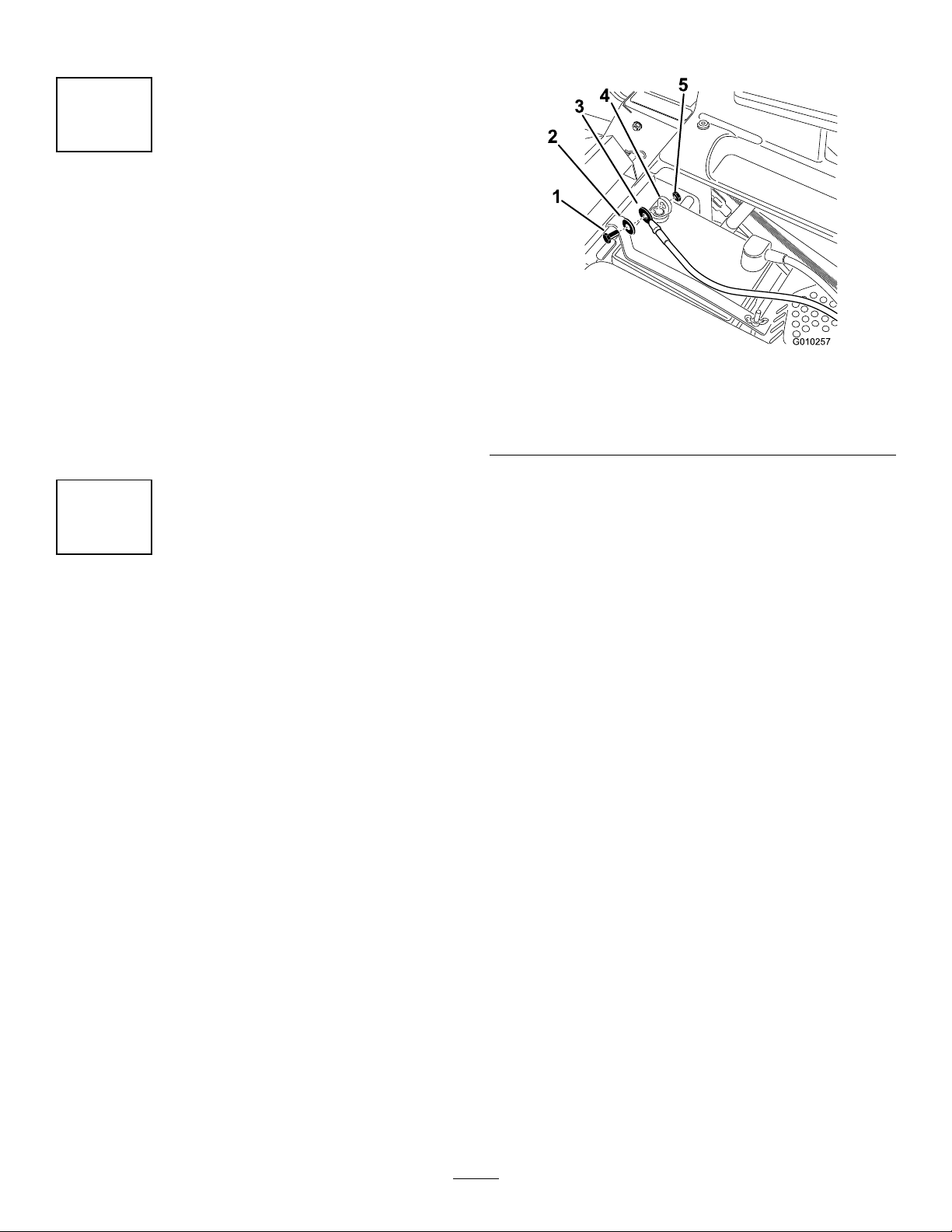
Note:Determinetheleftandrightsidesofthemachinefromthenormaloperatingposition.
G010257
1
2
3
5
4
1
ConnectingtheBattery
NoPartsRequired
Procedure
1.Locatethebatteryandnegativebatterycableinthe
centerofthemachine.
2.Removetheblackplasticcapfromthenegative
batterypost.Removethefastenersfromthenegative
batterycableandusethemtosecurethenegative
batterycabletothenegativebatterypost(
Figure1).
1.Bolt4.Negativebatterypost
2.Washer5.Nut
3.Negativebatterycable
Figure1
2
SettingUptheMotionControlLeversandtheSeat
NoPartsRequired
Procedure
1.Locatethemotioncontrolleversattachedbutfoldeddownonthemachine.
2.Removetheupperbolt(3/8x1inch)andwasher;loosenthelowerbolt(3/8x1inch).Raisethemotioncontrol
leverstotheuprightposition.
3.Aligntheholesinthemotioncontrolleverwiththeholesinthecontrolarmshaftandinstalltheboltandwasher
removedpreviously.Handtightenallfasteners.Repeatthisforbothcontrolslevers.
4.Setuptheseatasfollows(
Figure2):
2
Page 3
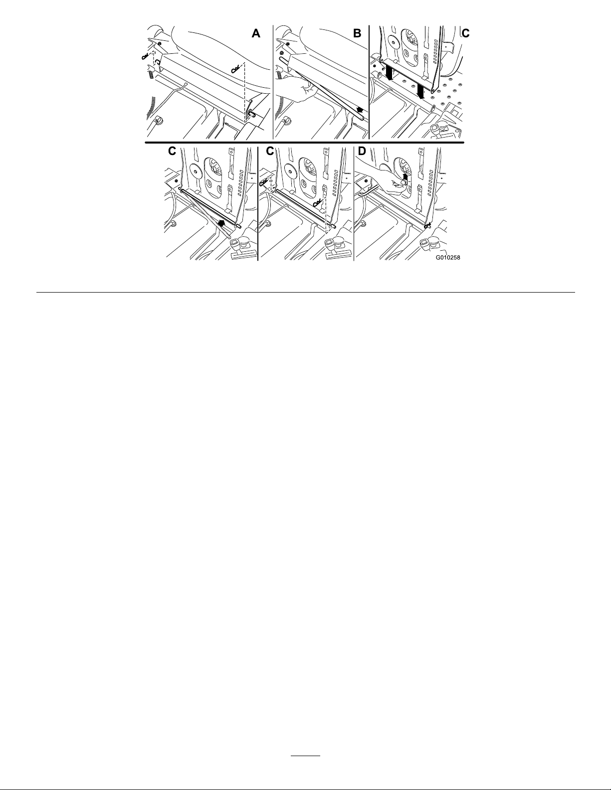
G010258
A B C
DC C
Figure2
A.Withthemotioncontrolleversintheoutward,neutrallockposition,removethehairpincottersontheseat
rodsecuringtheseattothemachine.
B.Slidetheseatrodoutfromthebracketsandseatframe.
C.Rotatetheseat180degreesandinstallitintothebracketyouremoveditfrom,usingtherodandhairpin
cottersremovedpreviously .
D.Connecttheinterlockswitchcabletotheseat.
E.Lowertheseatintotheoperatingposition.
5.Movethecontrolleversbacktothecenterposition(neutral).
6.Verifythemotioncontrolleversareproperlyaligned.Adjustasnecessary.Tightenallfasteners.
3
Page 4

3
13
14
15
g017895
16
InstallingtheRollOver
ProtectionSystem(ROPS)
Partsneededforthisprocedure:
1Rollbar
2Rollbarsupport
4Pivotbracket
4Flatspacer
2Pivotpinwithhairpinandlanyard
2
Reinforcingbracket
4Largewasher
2
Bolt(1/2x4–1/2inches)
8
Bolt(1/2x3–1/2inches)
2
Cylindricalspacer
4
Flatwasher(1/2inch)
8
Flangelocknut(1/2inch)
2
Hexlocknut(1/2inch)
2
Flangelocknut(5/16inch,maybepre-installed)
2
Conicalrubberbumper(maybepre-installed)
2
Smallrubberbumper(maybepre-installed)
2
Bolt(5/16x3–3/4inch)
2
Flatwasher(5/16inch)
2
Flangelocknut(5/16inch)
Figure4
1.Bolt(1/2x3–1/2inches)
(2)
2.Largewasher(4)10.Flangelocknut(1/2inch)
3.Rollbarsupport
4.Cutoutfacestherear12.Bolt(1/2x4–1/2inch)(2)
5.Brace,existing
6.Bolt(1/2x1–1/4inch)and
locknut(1/2inch),existing
7.Seatbeltassembly,
existing
8.Smallrubberbumper(2)
9.Hexlocknut(1/2inch)(2)
(2)
11.Reinforcingbracket(2)
13.Bolt(5/16x3–3/4inch)(2)
14.Flatwasher(5/16inch)(2)
15.Flangelocknut(5/16inch)
(2)
16.Engineguard
2.Loosenthelocknutthatsecuresthebracetothe
frame.Stopwhenthebraceswingsfreely(Figure4).
InstallingtheRollbarSupports
Completethefollowingstepsforbothleftandright
rollbarsupports.
1.Locatethefactoryinstalledbraceattachedtothe
framebetweentheengineandtherearwheel(see
Figure3andFigure4).
Note:Ifpreferred,therearwheelsmayberemoved
foreasieraccesstothebrace.
Figure3
Locationofthebraces
3.Attachtherollbarsupporttotheframeandthebrace
totherollbarsupportasshowninFigure4.Leave
theboltslooseenoughthatthepartsarefreetoshift
around.
Note:Ensurethatthecutoutatthetopofthe
supporttubefacestherearofthemachine.
Note:Notetheorientationofthereinforcing
bracket.
4.Attachtherollbarsupporttotheengineguardas
showninFigure4.
AttachingthePivotBrackets
Assemblethepivotbracketstotherollbarasshownin
Figure5.Leavetheboltslooseenoughthatthepartsare
freetoshiftaround.
Note:Ensurethatthelocknutsareontheinsideofthe
supporttube.
4
Page 5

Figure5
2
g017920
Note:Ensurethatthetabtowhichthelanyardis
attachedisangledawayfromthesurfaceofthepivot
bracket.
1.Bolt(1/2x3–1/2inches)
(4)
2.Flatwasher(4)5.Flangelocknut(4)
3.Pivotbracket,notchfacing
up(4)
4.Flatspacer(4)
6.Rollbar,cutoutfacing
down
AttachingtheRollbar
1.Insertthecylindricalspacerinthepivotholesinboth
rollbarsupports(Figure6).
Figure7
1.Bolt(1/2x3–1/2inch)(2)3.Flangelocknut(2)
2.Pivotpinwithhairpinand
lanyard(2)
4.Raisetherollbarintotheuprightpositionandlockit
inplacewithbothpivotpinsasshownin
Figure8.
Figure6
1.Cylindricalspacer
2.Largepivothole
2.Lifttherollbarwiththecutoutsinendsofthe
tubefacingupandalignthepivotholeswiththe
cylindricalspacersintherollbarsupports.
Note:Asecondpersontoperformthenextstep
willbehelpful.
3.Attachtherollbartotherollbarsupportsasshownin
Figure7.Leavetheboltsjustlooseenoughtoallow
therollbartofreelypivot.
Figure8
1.Rollbar3.Hairpin
2.Pivotpin4.Rollbar,uprightandlocked
MakingFinalAdjustments
1.Tightenthefastenersintheorderspeciedinthe
followingtable.Figure4andFigure5willhelp
identifytheparts.
5
Page 6

Sequence
1Threeboltsoneach
2Twoboltsoneach
3
4
DescriptionTorque
sideattachingthe
pivotbracketstothe
rollbarandrollbar
support.Ensure
thatthetabto
whichthelanyardis
attachedispointed
upward.
sideattachingthe
rollbarsupportto
theframeandthe
rollbarsupportto
thebrace.
Oneboltoneach
sideattaching
thebracestothe
machineframe.
Oneboltoneach
sideattachingthe
rollbartotheengine
guard.
400±40in-lbs
(45±.4N-m)
300±30in-lbs
(34±3N-m)
75±8ft-lbs
(102±11N-m)
60to80in-lbs.
(.4to.6N-m)
Note:Donotexceedtorquespecications.Doing
somaycausestructuraldamagetotheROPSorthe
frameofthemachine.
2.Ifnecessary,installbothsmallrubberbumpers.
Pressthesmallangeonthebackofeachintothe
holesonthebackoftherollbarsupports(
Figure4).
3.Removethepivotpinsandensurethattherollbar
pivotsfreelyupanddown.Ifitdoesnot,remove
therollbarandverifythatthecylindricalspacers
arecorrectlyinstalledaspreviouslydescribedin
AttachingtheRollbar.
Figure9
1.Conicalrubberbumper2.Flangenut(5/16inch)
5.Locktherollbarintheuprightpositionwiththe
pivotpins.Usethehairpinsattheendofeach
lanyardtosecurethepivotpins(Figure8).
Important:Thehairpinsattheendofboth
lanyardsmustbeinsertedintotheholesonthe
straightendofeachpivotpinuntiltheylockin
place.
4.Iftheconicalrubberbumpersarenotpre-installed,
unlocktherollbarandputitinthedownposition.
Installtheconicalrubberbumpersinsidethecutout
atthetopoftherollbarsupportsasshownin
Figure9.Securethemusingthe5/16inchange
nuts.
4
CompletingtheSetup
Partsneededforthisprocedure:
1
Hosecoupling(notincludedwithCEmodels)
1
Cutoffbafe(CEmodelsonly)
2
Bolt(5/16x5/8inch,54inchCEunitsonly)
1IgnitionKey
1
Operator'sManual
1
EngineOperator'sManual
1
OperatorTrainingMaterial
Procedure
6
Page 7

CheckingtheTirePressure
Checkthefrontandreartiresforproperination.Refer
toCheckingtheTirePressureintheOperator'sManual
fortherecommendedinationpressure.
CheckingtheSideDischargeChute
Removethepackingrestraintholdingthesidedischarge
chuteupandlowerthechuteintoplace.
CheckingtheEngineOilLevel
Beforeyoustarttheengineandusethemachine,check
theoillevelintheenginecrankcase;refertoChecking
theOilLevelintheOperator'sManual.
CheckingtheHydraulicOilLevel
Beforeyoustarttheengineandusethemachine,check
thehydraulicoillevelinthereservoirbehindtheseat;
refertoCheckingtheOilLevelintheOperator'sManual.
CheckingtheMowerAdjustment
Themowerdeckwasleveledatthefactory.Ifthemower
isnotcuttinglevel,adjusttheside-to-sidelevelandthe
front-to-rearbladeslope.SeetheOperator'sManualfor
theproperprocedure.
ReviewtheRemainingParts
Keepallthefollowingitemswiththemachine:
•IgnitionKey
•HoseCoupling(notincludedonCEmodels)
•Cutoffbafe(CEmodelsonly)
•5/16inchbolts(54inchCEunitsonly)
•Operator'sManual
•EngineOperator'sManual
•ViewtheOperatortrainingmaterial.
7
Page 8

 Loading...