

Page 1
TITANZero-Turn-RadiusRidingMowers
G010257
1
2
3
5
4
ModelNo.AllModels
LooseParts
Usethechartbelowtoverifythatallpartshavebeenshipped.
FormNo.3362-437RevA
SetupInstructions
ProcedureDescription
1
2
3
Nopartsrequired
Nopartsrequired
Hosecoupling(domesticunitsonly)
Cutoffbafe(54inchCEunitsonly)
Bolt(5/16x5/8inch)(54inchCEunits
only)
Locknut(5/16inch)(54inchCEunits
only)
IgnitionKey1
Operator’sManual
EngineOperator’sManual
OperatorTrainingMaterial
Qty.
–
–
1
1
2
1
1
1
Note:Determinetheleftandrightsidesofthemachinefromthenormaloperatingposition.
1
Use
Connectthebattery.
Setupthemotioncontrolleversandthe
seat.
Completethesetup.
ConnectingtheBattery
NoPartsRequired
Procedure
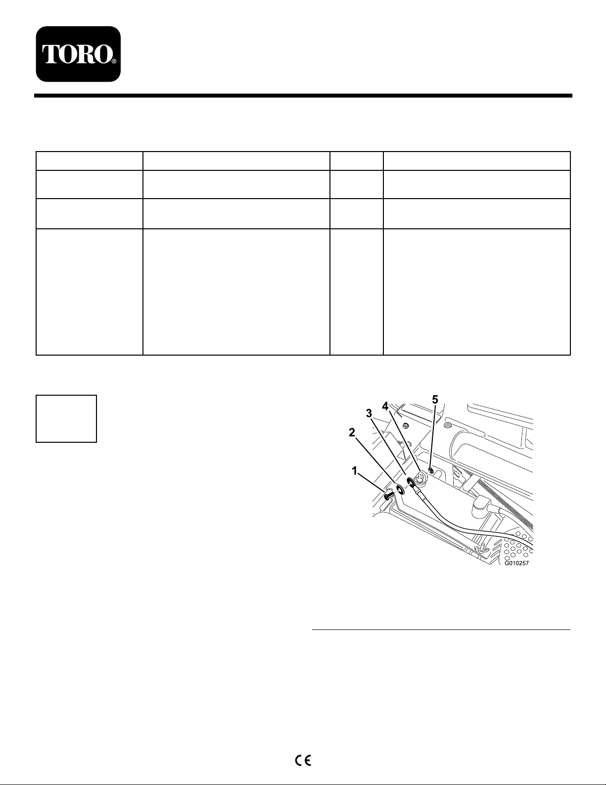
1.Locatethebatteryandnegativebatterycableinthe
centerofthemachine.
2.Removetheblackplasticcapfromthenegative
batterypost.Removethefastenersfromthenegative
batterycableandusethemtosecurethenegative
batterycabletothenegativebatterypost(Figure1).
1.Bolt4.Negativebatterypost
2.Washer5.Nut
3.Negativebatterycable
©2009—TheT oro®Company
8111LyndaleAvenueSouth
Bloomington,MN55420
Registeratwww.T oro.com.
Figure1
OriginalInstructions(EN)
PrintedintheUSA.
AllRightsReserved
Page 2
2
G010256
G010258
A B C
DC C
SettingUptheMotionControlLeversandtheSeat
NoPartsRequired
Procedure
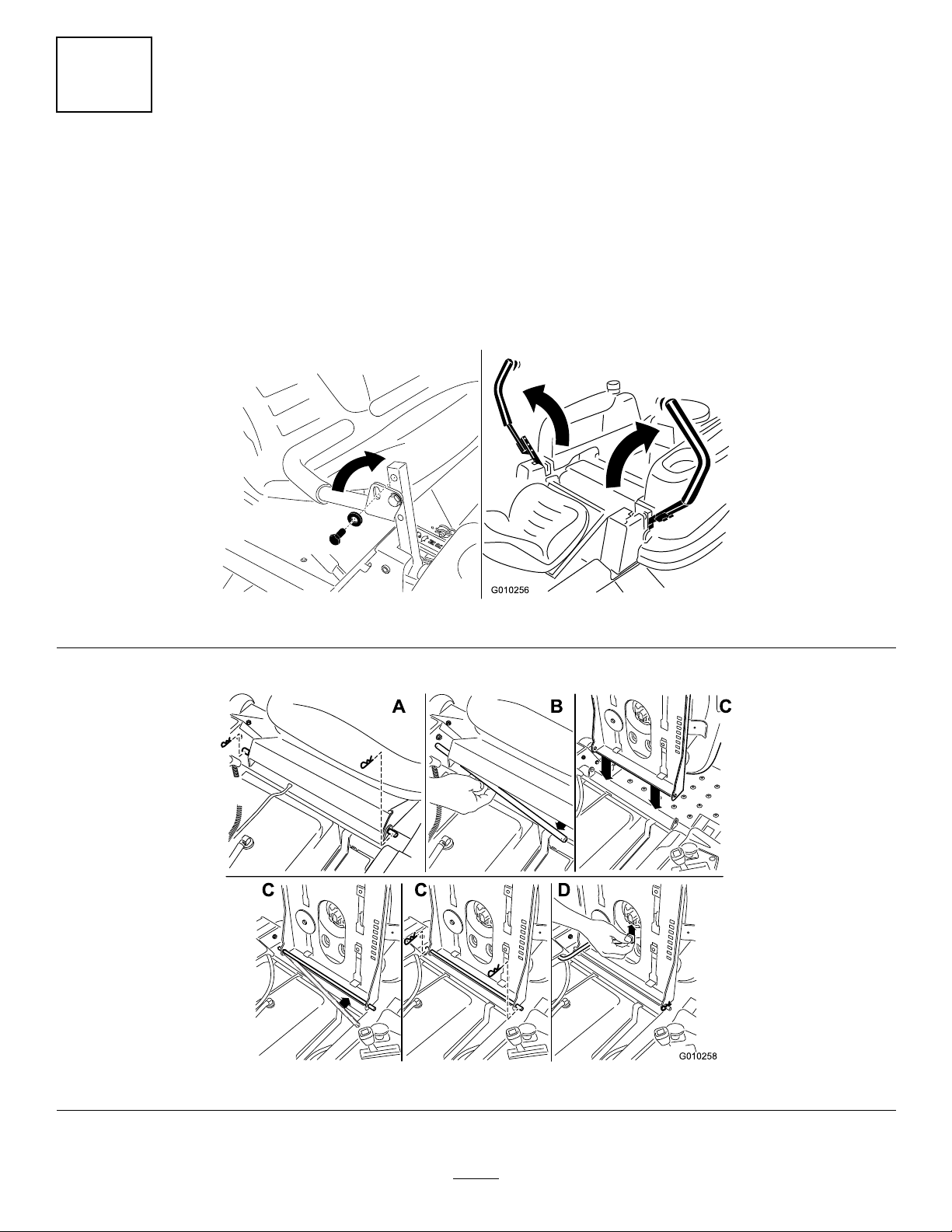
1.Removetheupperbolt(3/8x1inch)andwasher;loosenthelowerbolt(3/8x1inch)asshowninFigure2.
2.Aligntheholesinthemotioncontrolleverwiththeholesinthecontrolarmshaftandinstalltheboltandwasher
removedpreviously(Figure2).Handtightenallfasteners.Repeatthisforbothcontrolslevers.Movethe
motioncontrolleversintotheneutrallockposition.
3.Setuptheseatasfollows(Figure3):
Figure2
Figure3
A.Removethehairpincottersontheseatrodsecuringtheseattothemachine.
2
Page 3
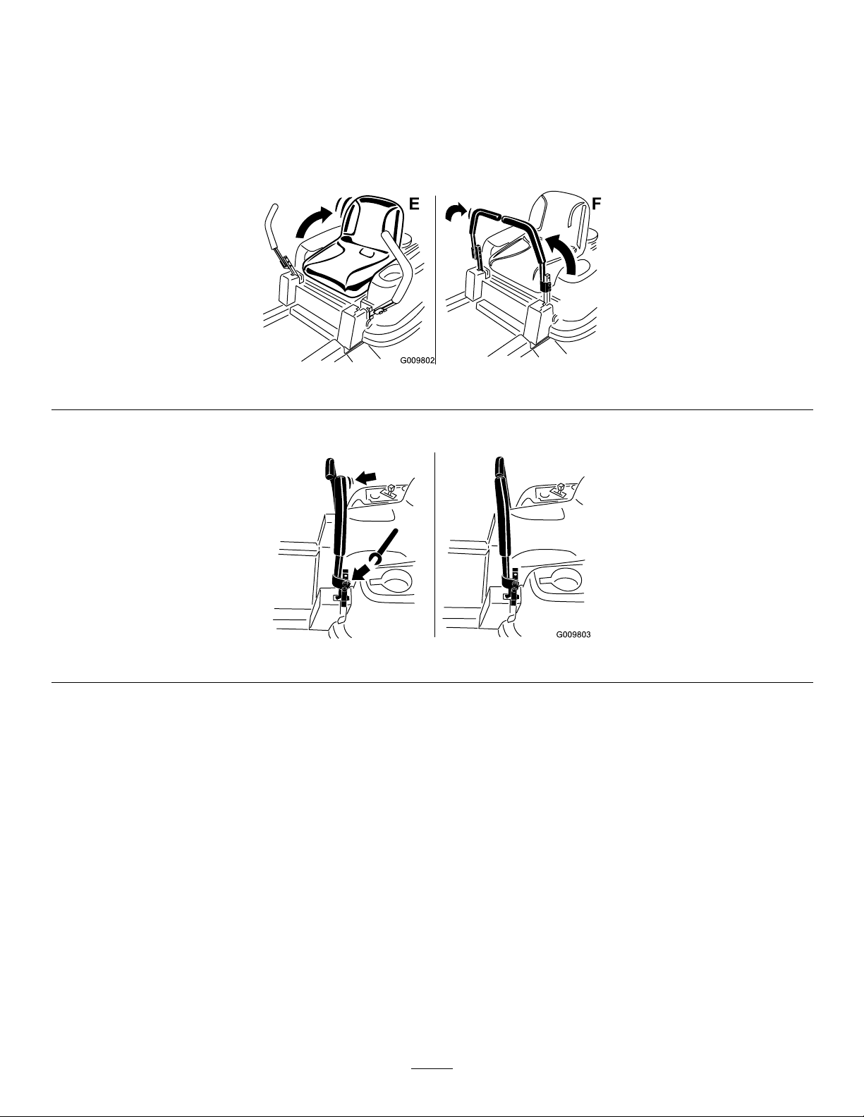
B.Slidetheseatrodoutfromthebracketsandseatframe.
G009802
E F
G009803
C.Rotatetheseat180degreesandinstallitintothebracketyouremoveditfrom,usingtherodandhairpin
cottersremovedpreviously.
D.Connecttheinterlockswitchcabletotheseat.
E.Lowertheseatintotheoperatingposition(Figure4).
F.Movethecontrolleversbacktothecenterposition(neutral)asshowninFigure4.
Figure4
4.Verifythemotioncontrolleversareproperlyaligned(Figure5).Adjustasnecessary.Tightenallfasteners.
Figure5
3
Page 4

•Stopfasteners,deck(54inchCEunitsonly)
•Operator’sManual
3
•EngineOperator’sManual
CompletingtheSetup
Partsneededforthisprocedure:
1
Hosecoupling(domesticunitsonly)
1
Cutoffbafe(54inchCEunitsonly)
2
Bolt(5/16x5/8inch)(54inchCEunitsonly)
Locknut(5/16inch)(54inchCEunitsonly)
1IgnitionKey
1
Operator’sManual
1
EngineOperator’sManual
1
OperatorTrainingMaterial
Procedure
CheckingtheTirePressure
Checkthefrontandreartiresforproperination.Refer
toCheckingtheTirePressureintheOperator’sManualfor
therecommendedinationpressure.
•ViewtheOperatortrainingmaterial.
CheckingtheSideDischargeChute
Removethepackingrestraintholdingthesidedischarge
chuteupandlowerthechuteintoplace.
CheckingtheEngineOilLevel
Beforeyoustarttheengineandusethemachine,check
theoillevelintheenginecrankcase;refertoChecking
theOilLevelintheOperator’ sManual.
CheckingtheHydraulicOilLevel
Beforeyoustarttheengineandusethemachine,check
thehydraulicoillevelinthereservoirbehindtheseat;
refertoCheckingtheOilLevelintheOperator’sManual.
CheckingtheMowerAdjustment
Themowerdeckwasleveledatthefactory.Ifthemower
isnotcuttinglevel,adjusttheside-to-sidelevelandthe
front-to-rearbladeslope.SeetheOperator’sManual
fortheproperprocedure.
ReviewtheRemainingParts
Keepallthefollowingitemswiththemachine:
•IgnitionKey
•HoseCoupling(domesticunitsonly)
•Cutoffbafe(54inchCEunitsonly)
4
 Loading...