

Page 1

FormNo.3424-723RevA
ZMaster
®
Professional6000
SeriesRidingMower
with122cm,132cm,or152cmTURBO
FORCE
ModelNo.74902TE—SerialNo.403138033andUp
ModelNo.74919TE—SerialNo.403227085andUp
ModelNo.74925TE—SerialNo.403138045andUp
ModelNo.74942TE—SerialNo.402364843andUp
ModelNo.75969TE—SerialNo.403100000andUp
®
Mower
Registeratwww.T oro.com.
OriginalInstructions(EN)
*3424-723*A
Page 2
ThisproductcomplieswithallrelevantEuropean
directives;fordetails,pleaseseetheseparateproduct
specicDeclarationofConformity(DOC)sheet.
codeorvisitwww.Toro.com.Youmayalsocallus
at1-888-384-9939torequestawrittencopyofthe
productwarranty.
GrossorNetTorque:Thegrossornettorque
ofthisenginewaslaboratoryratedbytheengine
manufacturerinaccordancewiththeSocietyof
AutomotiveEngineers(SAE)J1940orJ2723.As
conguredtomeetsafety,emission,andoperating
requirements,theactualenginetorqueonthisclass
ofmowerwillbesignicantlylower.
Pleaserefertotheenginemanufacturer’sinformation
includedwiththemachine.
WARNING
CALIFORNIA
Proposition65Warning
Theengineexhaustfromthisproduct
containschemicalsknowntotheStateof
Californiatocausecancer,birthdefects,
orotherreproductiveharm.
Batteryposts,terminals,andrelated
accessoriescontainleadandlead
compounds,chemicalsknownto
theStateofCaliforniatocause
cancerandreproductiveharm.Wash
handsafterhandling.
Useofthisproductmaycauseexposure
tochemicalsknowntotheStateof
Californiatocausecancer,birthdefects,
orotherreproductiveharm.
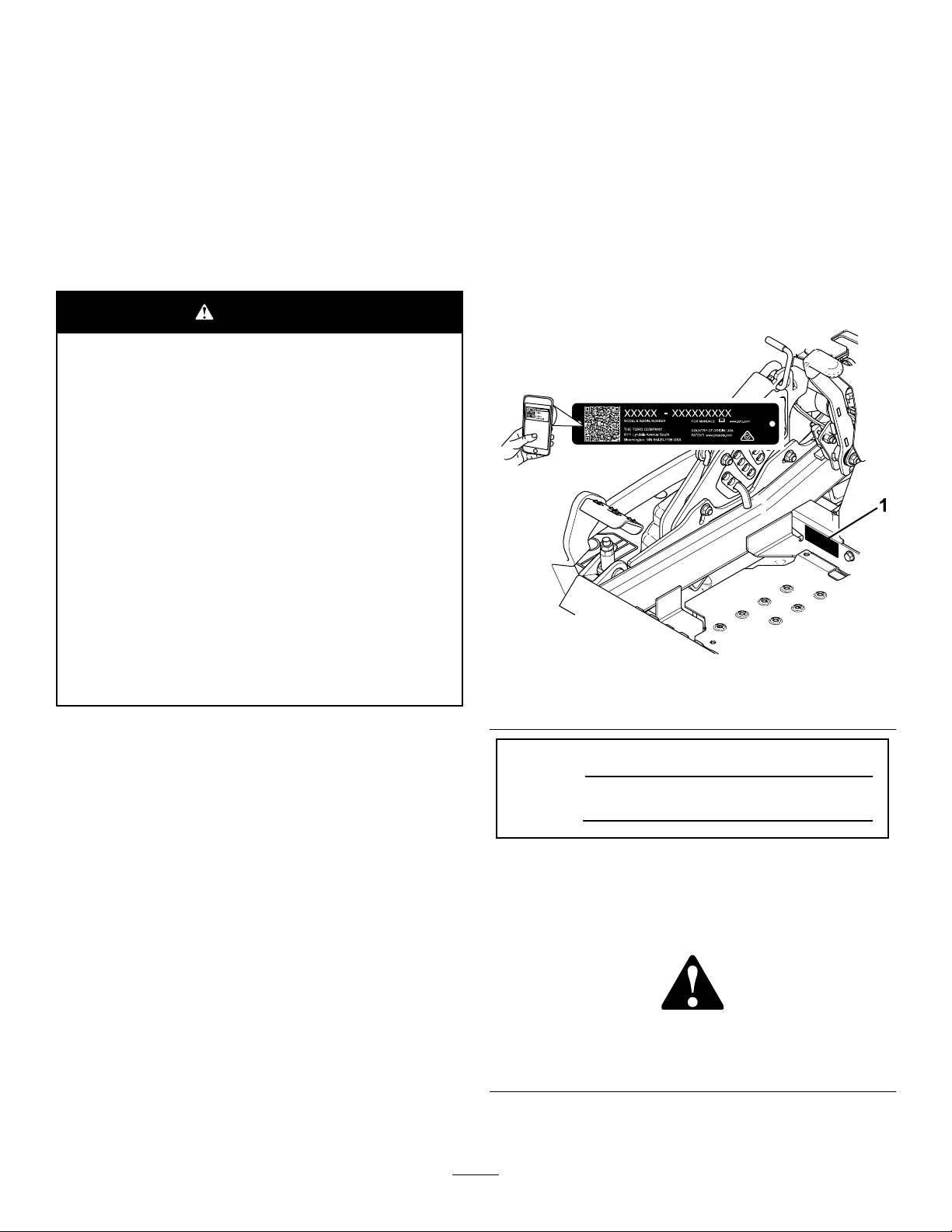
Wheneveryouneedservice,genuineToroparts,or
additionalinformation,contactanAuthorizedService
DealerorToroCustomerServiceandhavethemodel
andserialnumbersofyourproductready.Figure1
identiesthelocationofthemodelandserialnumbers
ontheproduct.Writethenumbersinthespace
provided.
Important:Withyourmobiledevice,youcan
scantheQRcode(ifequipped)ontheserial
numberdecaltoaccesswarranty,parts,andother
productinformation.
g233771
Figure1
Introduction
Thisrotary-blade,ridinglawnmowerisintendedtobe
usedbyprofessional,hiredoperators.Itisdesigned
primarilyforcuttinggrassonwell-maintainedlawnson
residentialorcommercialproperties.Itisnotdesigned
forcuttingbrushorforagriculturaluses.
Readthisinformationcarefullytolearnhowtooperate
andmaintainyourproductproperlyandtoavoid
injuryandproductdamage.Youareresponsiblefor
operatingtheproductproperlyandsafely.
YoumaycontactTorodirectlyatwww.T oro.com
forproductsafetyandoperationtrainingmaterials,
accessoryinformation,helpndingadealer,orto
registeryourproduct.
FortheOperator’sManual,thecompletewarranty
details,ortoregisteryourproduct,usetheQR
1.Modelandserialnumberlocation
ModelNo.
SerialNo.
Thismanualidentiespotentialhazardsandhas
safetymessagesidentiedbythesafety-alertsymbol
(Figure2),whichsignalsahazardthatmaycause
seriousinjuryordeathifyoudonotfollowthe
recommendedprecautions.
g000502
Figure2
Safety-alertsymbol
Thismanualuses2wordstohighlightinformation.
Importantcallsattentiontospecialmechanical
©2018—TheToro®Company
8111LyndaleAvenueSouth
Bloomington,MN55420
Contactusatwww.Toro.com.
2
PrintedintheUSA
AllRightsReserved
Page 3

informationandNoteemphasizesgeneralinformation
worthyofspecialattention.
Contents
Safety.......................................................................4
GeneralSafety...................................................4
SlopeIndicator...................................................5
SafetyandInstructionalDecals..........................6
ProductOverview...................................................14
Controls...........................................................14
Specications..................................................16
MachineswithSideDischarge..........................16
MachineswithRearDischarge.........................17
BeforeOperation.................................................17
BeforeOperationSafety...................................17
PerformingDailyMaintenance..........................19
BreakinginaNewMachine..............................19
UsingtheRollover-ProtectionSystem
(ROPS).........................................................19
UsingtheSafety-InterlockSystem....................20
PositioningtheSeat..........................................22
UnlatchingtheSeat..........................................22
ChangingtheSeatSuspension.........................22
AdjustingtheMyRide™Suspension
System..........................................................23
DuringOperation.................................................24
DuringOperationSafety...................................24
EnteringtheOperator’sPosition.......................25
OperatingtheParkingBrake.............................26
OperatingtheMowerBlade-ControlSwitch
(PTO)............................................................26
OperatingtheThrottle.......................................26
OperatingtheChoke........................................27
StartingtheEngine...........................................27
ShuttingOfftheEngine.....................................28
UsingtheMotion-ControlLevers.......................28
DrivingtheMachine..........................................28
UsingtheSideDischarge.................................30
AdjustingtheHeightofCut...............................30
AdjustingtheAnti-ScalpRollers........................31
AdjustingtheAnti-ScalpRollers........................32
AdjustingtheSkid(s).........................................33
AdjustingtheFlowBafeCamLocks................33
PositioningtheFlowBafe................................34
OperatingTips.................................................35
AfterOperation....................................................35
AfterOperationSafety......................................35
UsingtheFuel-ShutoffValve.............................35
UsingtheDrive-Wheel-ReleaseV alves............36
TransportingtheMachine.................................37
UsingtheZStand
Maintenance...........................................................40
RecommendedMaintenanceSchedule(s)...........40
Pre-MaintenanceProcedures..............................41
MaintenanceSafety..........................................41
ReleasingtheMower-DeckCurtain..................41
TM
..........................................38
RemovingtheSheet-MetalGuard.....................42
Lubrication..........................................................42
GreasingtheMachine.......................................42
AddingLightOilorSprayLubrication................42
GreasingtheMowerDeck................................43
LubricatingtheCaster-WheelHubs..................44
EngineMaintenance...........................................45
EngineSafety...................................................45
ServicingtheAirCleaner..................................45
ServicingtheEngineOil....................................46
ServicingtheSparkPlug...................................49
CheckingtheSparkArrester.............................50
FuelSystemMaintenance...................................51
ReplacingtheFuelFilter...................................51
ServicingtheFuelT ank.....................................51
ElectricalSystemMaintenance...........................51
ElectricalSystemSafety...................................51
ServicingtheBattery.........................................51
ServicingtheFuses..........................................53
DriveSystemMaintenance..................................54
CheckingtheSeatBelt.....................................54
CheckingtheRoll-BarKnobs............................54
AdjustingtheTracking......................................55
CheckingtheTirePressure...............................55
CheckingtheWheelLugNuts...........................55
CheckingtheWheel-HubSlottedNut................55
AdjustingtheCaster-PivotBearing...................56
UsingtheClutchShim......................................56
CoolingSystemMaintenance..............................58
CleaningtheEngineScreenandEngine-Oil
Cooler...........................................................58
CleaningtheEngine-CoolingFinsand
Shrouds........................................................59
CheckingandCleaningtheHydraulic-Unit
Shrouds........................................................59
BrakeMaintenance.............................................60
AdjustingtheParkingBrake..............................60
BeltMaintenance................................................61
InspectingtheBelts..........................................61
ReplacingtheMowerBeltforSide-Discharge
MowerDecks................................................61
ReplacingtheMowerBeltforRear-Discharge
MowerDecks................................................62
ReplacingtheHydraulicPump-Drive
Belt................................................................64
ControlsSystemMaintenance.............................65
AdjustingtheControl-HandlePosition..............65
AdjustingtheMotion-ControlLinkage...............65
AdjustingtheMotion-ControlDamper...............66
AdjustingtheMotion-ControlNeutral-Lock
Pivot..............................................................67
HydraulicSystemMaintenance...........................67
HydraulicSystemSafety...................................67
ServicingtheHydraulicSystem........................67
MowerDeckMaintenance....................................69
LevelingtheMowerDeck..................................69
ServicingtheCuttingBlades.............................72
RemovingtheMowerDeck...............................74
3
Page 4

ReplacingtheGrassDeector..........................76
Cleaning..............................................................77
CleaningundertheMowerDeck.......................77
CleaningtheSuspensionSystem.....................77
DisposingofWaste...........................................77
Storage...................................................................77
StorageSafety..................................................77
CleaningandStorage.......................................77
Troubleshooting......................................................79
Schematics.............................................................81
Safety
Thismachinehasbeendesignedinaccordancewith
ENISO5395:2013.
GeneralSafety
Thisproductiscapableofamputatinghandsand
feetandofthrowingobjects.Alwaysfollowallsafety
instructionstoavoidseriouspersonalinjury .
Usingthisproductforpurposesotherthanitsintended
usecouldprovedangeroustoyouandbystanders.
•Alwayskeeptherollbarinthefullyraisedand
lockedpositionandusetheseatbelt.
•Donotoperatethemachineneardrop-offs,
ditches,embankments,water,orotherhazards,or
onslopesgreaterthan15degrees.
•Readandunderstandthecontentsofthis
Operator’sManualbeforestartingtheengine.
•Donotputyourhandsorfeetnearmoving
componentsofthemachine.
•Donotoperatethemachinewithoutallguards
andothersafetyprotectivedevicesinplaceand
workingonthemachine.
•Keepchildrenandbystandersoutoftheoperating
area.Neverallowchildrentooperatethemachine.
•Stopthemachine,shutofftheengine,andremove
thekeybeforeservicing,fueling,orunclogging
themachine.
Improperlyusingormaintainingthismachinecan
resultininjury .T oreducethepotentialforinjury,
complywiththesesafetyinstructionsandalwayspay
attentiontothesafety-alertsymbol,whichmeans
Caution,Warning,orDanger—personalsafety
instruction.Failuretocomplywiththeseinstructions
mayresultinpersonalinjuryordeath.
Youcanndadditionalsafetyinformationwhere
neededthroughoutthismanual.
4
Page 5
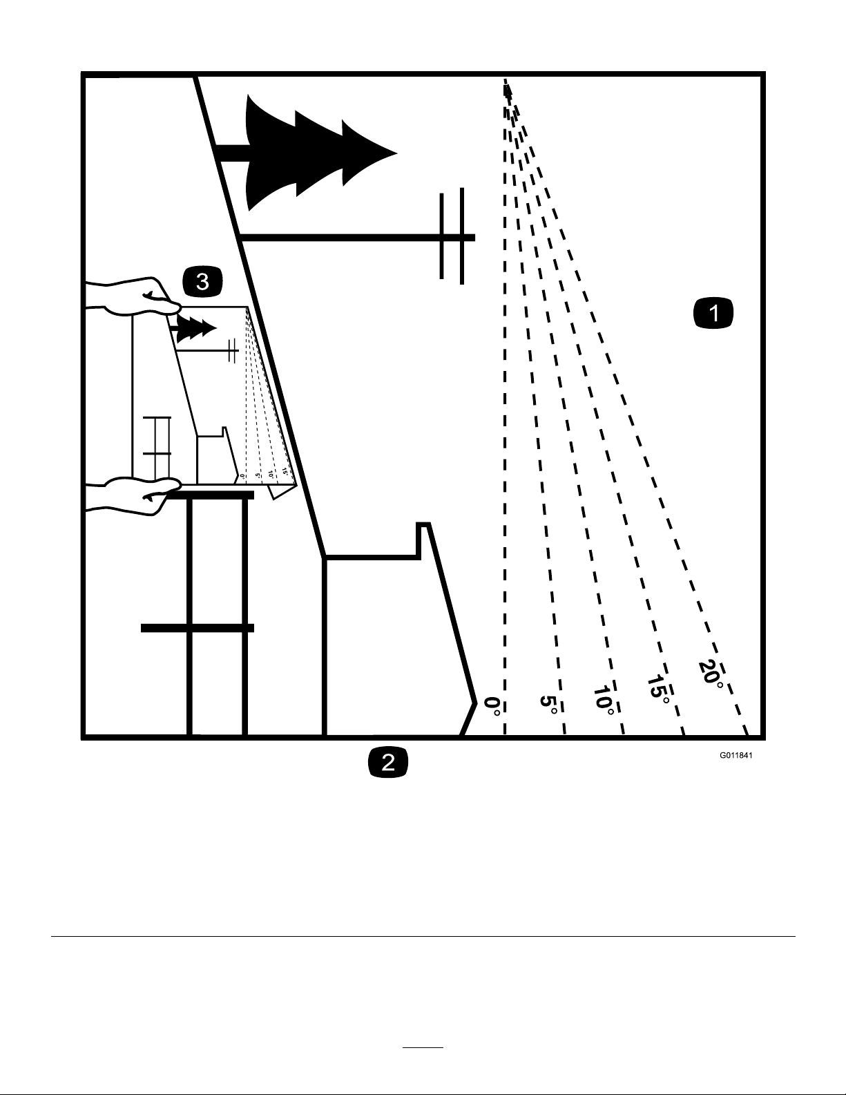
SlopeIndicator
Figure3
Youmaycopythispageforpersonaluse.
1.Themaximumslopeyoucanoperatethemachineonis15degrees.Usetheslopecharttodeterminethedegreeofslopeof
hillsbeforeoperating.Donotoperatethismachineonaslopegreaterthan15degrees.Foldalongtheappropriateline
tomatchtherecommendedslope.
2.Alignthisedgewithaverticalsurface,atree,building,fencepole,etc.
3.Exampleofhowtocompareslopewithfoldededge
5
g011841
Page 6
SafetyandInstructionalDecals
Safetydecalsandinstructionsareeasilyvisibletotheoperatorandarelocatednearanyarea
ofpotentialdanger.Replaceanydecalthatisdamagedormissing.
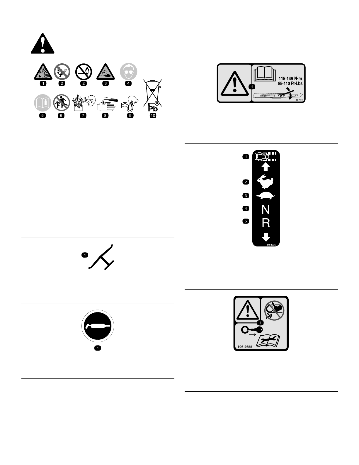
BatterySymbols
Someorallofthesesymbolsareonyourbattery
decal93-7818
93-7818
decalbatterysymbols
1.Warning—readtheOperator'sManualforinstructionson
torquingthebladebolt/nutto1 15to149N∙m(85to110
ft-lb).
1.Explosionhazard
6.Keepbystandersasafe
distanceawayfromthe
battery.
2.Nore,opename,or
smoking
7.Weareyeprotection;
explosivegasescan
causeblindnessandother
injuries.
3.Causticliquid/chemical
burnhazard
8.Batteryacidcancause
blindnessorsevereburns.
4.Weareyeprotection.9.Flusheyesimmediately
withwaterandgetmedical
helpfast.
5.ReadtheOperator's
Manual.
10.Containslead;donot
discard
Manufacturer'sMark
1.Indicatesthebladeisidentiedasapartfromtheoriginal
machinemanufacturer.
decal99-8936
99-8936
1.Machinespeed4.Neutral
decaloemmarkt
2.Fast5.Reverse
3.Slow
decal58-6520
58-6520
1.Grease
1.Warning-donottouchorapproachmovingbelts;remove
106-2655
decal106-2655
theignitionkeyandreadtheinstructionsbeforeservicing
orperformingmaintenance.
6
Page 7
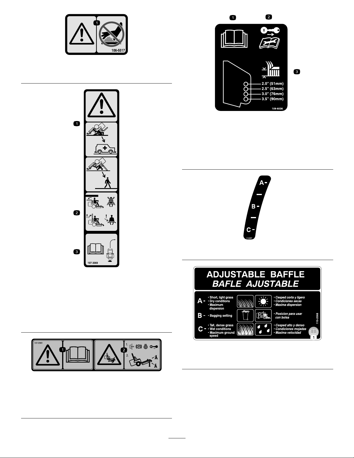
1.Warning—donottouchthehotsurface.
decal106-5517
106-5517
decal109-6036
109-6036
MachineswithRearDischargeOnly
1.ReadtheOperator’sManual.
2.Removethekeyfromthekeyswitchandreadthe
instructionsbeforeservicingorperformingmaintenance.
3.Heightofcut
decal107-3069
107-3069
1.Warning–thereisnorolloverprotectionwhentherollbaris
down.
2.Toavoidinjuryordeathfromarolloveraccident,keepthe
rollbarintheraisedandlockedpositionandweartheseat
belt.Lowertherollbaronlywhenabsolutelynecessary;do
notweartheseatbeltwhentherollbarisdown.
3.ReadtheOperator'sManual;driveslowlyandcarefully.
decal107-3969
107-3969
1.Warning—readtheOperator'sManual.
2.Crushinghazard,mower—engagetheparkingbrake,shut
offtheengine,andremovethekeybeforeworkingunder
themower.
decal110-2067
110-2067
decal110-2068
110-2068
1.ReadtheOperator'sManual.
7
Page 8
decal112-9028
112-9028
1.Warning—stayawayfrommovingparts;keepallguardsin
place.
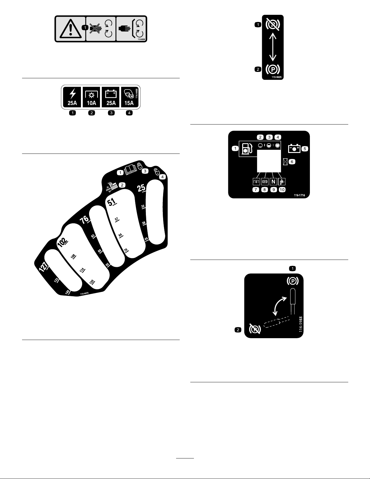
decal115-9625
115-9625
MachineswithMyRide™Only
114-4466
1.Main(25A)3.Charge(25A)
2.PTO(10A)4.Auxiliary(15A)
1.Parking
decal114-4466
brake—disengaged
2.Parkingbrake—engaged
decal116-1716
116-1716
1.Fuel6.Hourmeter
2.Empty
3.Half
4.Full9.Neutral
5.Battery
7.PTO
8.Parkingbrake
10.Operator-presenceswitch
1.ReadtheOperator's
Manual.
2.Heightofcut
decal114-4470
114-4470
3.Locked
4.Unlocked
decal116-5988
116-5988
MachineswithoutMyRide™Only
1.Parkingbrake—engaged2.Parking
brake—disengaged
8
Page 9
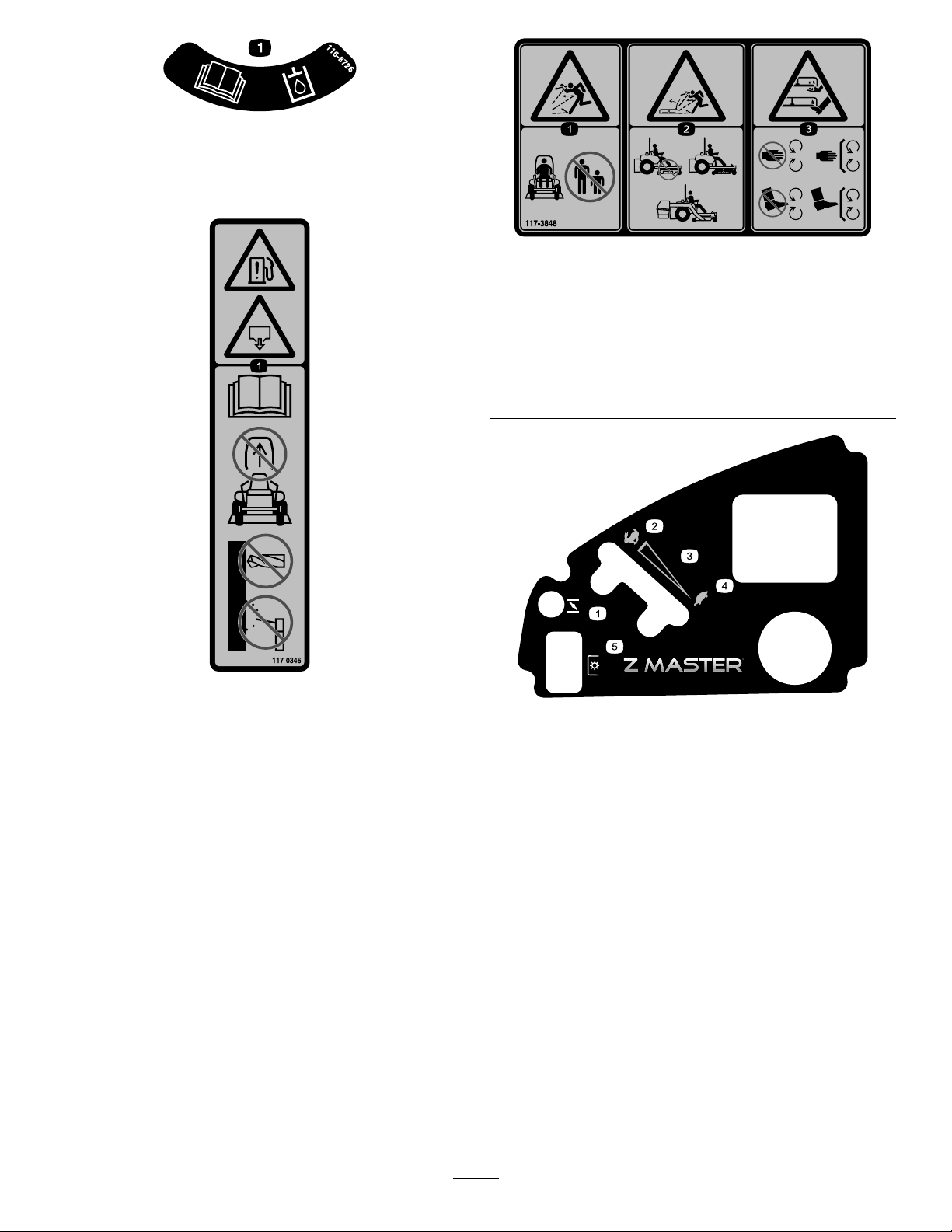
116-8726
1.ReadtheOperator’sManualfortherecommendedhydraulic
uid.
decal116-8726
decal117-3848
117-3848
1.Thrownobjecthazard—keepbystandersasafedistance
awayfromthemachine.
2.Thrownobjecthazard,mower—donotoperatethemachine
withoutthedeector,dischargecover,orgrasscollection
systeminplace.
3.Cutting/dismembermentofhandorfoot—stayawayfrom
movingparts;keepallguardsandshieldsinplace.
117-0346
1.Fuelleakhazard—readtheOperator'sManual;donot
attempttoremovetherollbar;donotweld,drill,ormodify
therollbarinanyway.
decal117-0346
decal120-5897
120-5897
1.Chokecontrol4.Slow
2.Fast
3.Continuous-variable
setting
5.Powertakeoff(PTO),
blade-controlswitch
9
Page 10
120-5898
1.Choke4.Slow
2.Fast
5.Powertakeoff(PTO),
blade-controlswitch
3.Continuous-variable
setting
126-2055
1.Wheellugnuttorque95ft-lb(129N∙m)(4x)
2.Wheelhubnuttorque235ft-lb(319N∙m)
3.ReadandunderstandtheOperator’sManualbefore
performinganymaintenance,checktorqueafterrst100
hoursthenevery500hoursthereafter.
decal120-5898
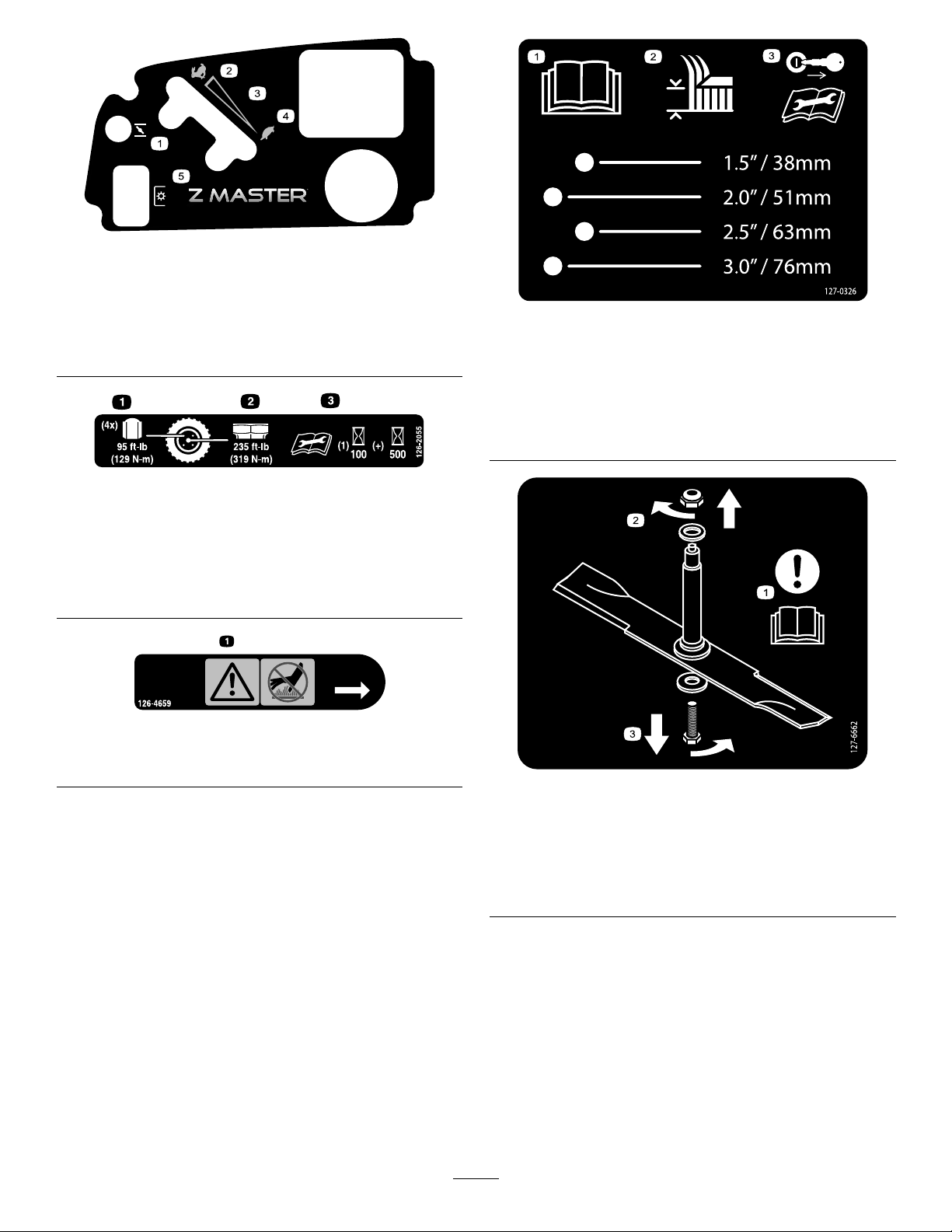
decal127-0326
127-0326
1.ReadtheOperator's
Manual.
2.Height-of-cut
decal126-2055
3.Removethekeyfrom
theignitionandreadthe
Operator'sManualbefore
performingmaintenance
orservicingthemachine.
126-4659
1.Warning—hotpulley;allowtocool.
decal126-4659
decal127-6662
127-6662
RearDischargeMowersOnly
1.Attention—readthe
Operator'sManual.
2.Removethenutbyturning
itclockwise.
3.Removetheboltbyturning
itcounterclockwise.
10
Page 11
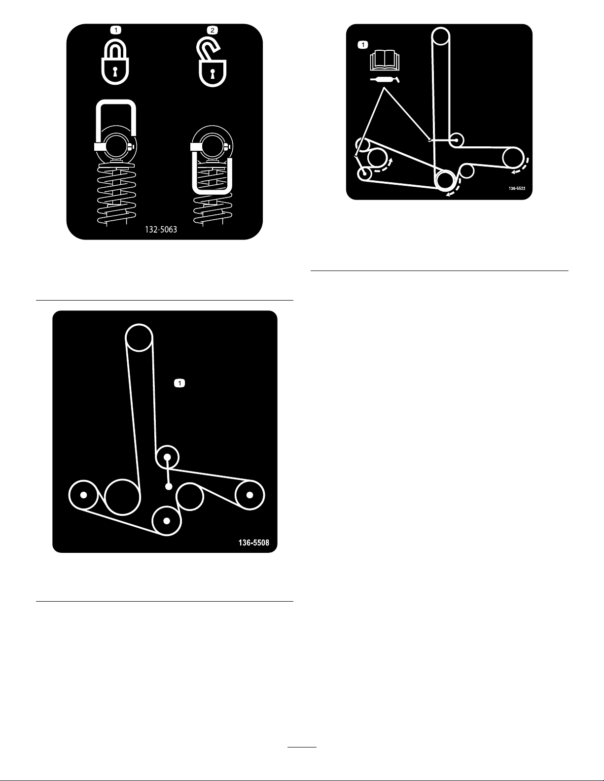
132-5063
MachineswithMyRide™Only
1.Camlock2.Camunlock
decal136-5522
136-5522
Rear-DischargeMachinesOnly
decal132-5063
1.Beltrouting;readtheOperator’sManualforgreasing
information.
decal136-5508
136-5508
1.Beltrouting
11
Page 12
decal114-4468
114-4468
1.Warning—readtheOperator'sManual.5.Lossoftraction/controlhazard,slopes—lossoftraction/control
onaslope,disengagetheblade-controlswitch(PTO),and
proceedofftheslopeslowly.
2.Warning—donotoperatethismachineunlessyouaretrained.
6.Crushing/dismembermenthazardofbystanders—donotcarry
passengers,andlookforwardanddownwhenoperatingthe
machine,lookbehindanddownwhenreversing.
3.Warning—engagetheparkingbrake,shutofftheengine,
andremovethekey;readtheinstructionsbeforeservicing
7.Cutting/dismembermenthazard;handorfoot—stayaway
frommovingpartsandkeepallguardsandshieldsinplace.
orperformingmaintenance.
4.Thrownobjecthazard—Shutofftheengineandpickupdebris
beforeoperating,keepbystandersasafedistanceawayfrom
themachine,andkeepthedeectorinplace.
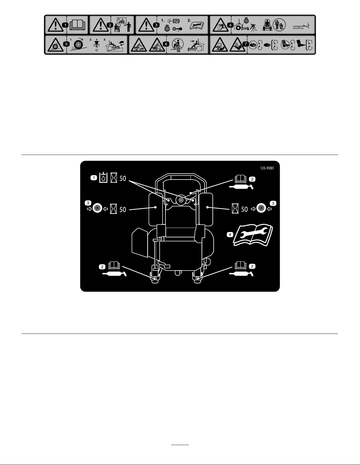
125-9383
1.Checkthehydraulicuidevery50operatinghours.3.Checkthetirepressureevery50operatinghours.
2.ReadtheOperator’sManualforinformationonlubricating
themachine.
4.ReadtheOperator’sManualbeforeservicingorperforming
maintenance.
12
decal125-9383
Page 13
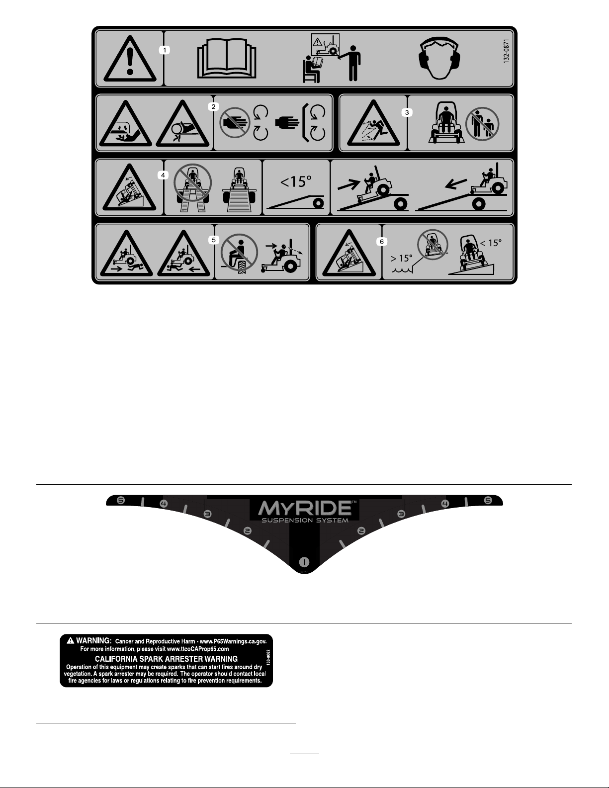
132-0871
Note:Thismachinecomplieswiththeindustrystandardstabilitytestinthestaticlateralandlongitudinaltestswiththemaximum
recommendedslopeindicatedonthedecal.ReviewtheinstructionsforoperatingthemachineonslopesintheOperator’sManualas
wellastheconditionsinwhichyouwouldoperatethemachinetodeterminewhetheryoucanoperatethemachineinthoseconditions
onthatdayandatthatsite.Changesintheterraincanresultinachangeinslopeoperationforthemachine.Ifpossible,keepthe
cuttingunitsloweredtothegroundwhileoperatingthemachineonslopes.Raisingthecuttingunitswhileoperatingonslopescan
causethemachinetobecomeunstable.
decal132-0871
1.Warning—readtheOperator’sManual;donotoperatethis
machineunlessyouaretrained;wearhearingprotection.
4.Ramphazard—whenloadingontoatrailer,donotusedual
ramps;onlyuseasingularrampwideenoughforthemachine
andthathasaninclinelessthan15°;backuptheramp(in
reverse)anddriveforwardofftheramp.
2.Cutting,dismembering,andentanglementhazard—keep
handsawayfrommovingparts;keepallguardsandshieldsin
5.Bodilyharmhazard—donotcarrypassengers;lookbehind
youwhenmowinginreverse.
place.
3.Thrownobjecthazard—keepbystandersaway.6.Tippinghazardonslopes—donotuseonslopesnearopen
water;donotuseonslopesgreaterthan15°.
132-5067
MachineswithMyRide™Only
decal132-5067
decal133-8062
133-8062
13
Page 14
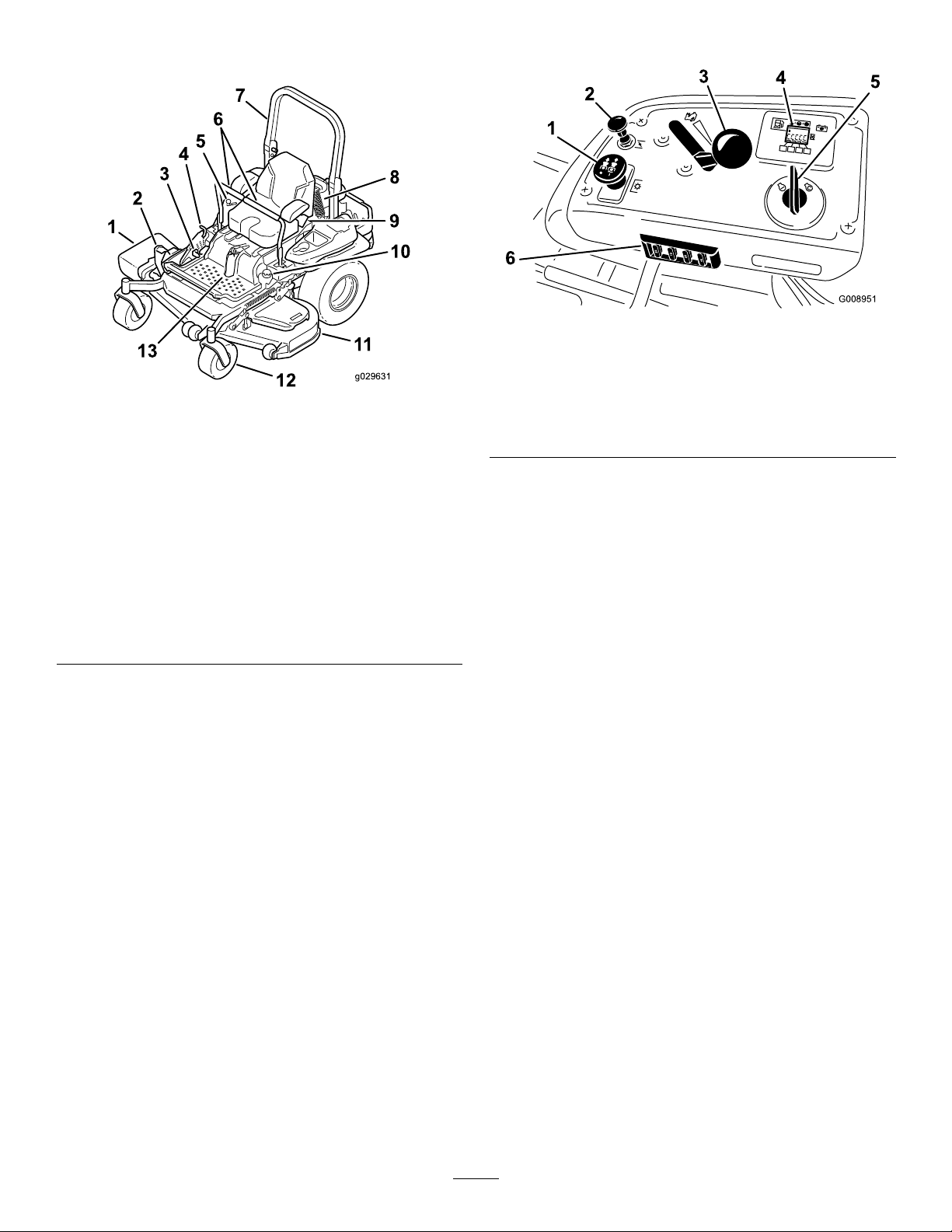
ProductOverview
ControlPanel
g008951
Figure5
Figure4
1.Side-dischargedeector
2.Height-of-cutdecklift
pedal
3.Parking-brakelever10.Fuelcap
4.Transportlock11.Mowerdeck
5.Controls12.Casterwheel
6.Motion-controllevers13.Front-shockassembly
7.Rollbar
8.Rear-shockassembly
(machineswithMyRide™
only)
9.Seatbelt
(machineswithMyRide™
only)
Controls
Becomefamiliarwithallthecontrolsbeforeyoustart
theengineandoperatethemachine(Figure4and
Figure5).
1.Blade-controlswitch
(powertakeoff)
g029631
2.Chokecontrol
3.Throttlecontrol6.Fuses
4.Hour
meter/Safety-interlock
display
5.Keyswitch
HourMeter
Thehourmeterrecordsthenumberofhoursthe
enginehasoperated.Itoperateswhentheengine
isrunning.Usethesetimesforschedulingregular
maintenance(Figure6).
FuelGauge
Thefuelgaugeislocatedwithinthehourmeter,and
thebarslightupwhenthekeyswitchisintheON
position(Figure6).
Theindicatorlightappearswhenthefuellevelislow
(approximately1gallonremaininginthefueltank).
Safety-InterlockIndicators
Therearesymbolsonthehourmeterthatindicate
withablacktrianglethattheinterlockcomponentis
positionedcorrectly(Figure6).
Battery-IndicatorLight
IfyouturnthekeyswitchtotheONpositionfora
fewseconds,thebatteryvoltagedisplaysinthearea
wherethehoursarenormallydisplayed.
Thebatterylightturnsonwhentheignitionisturned
onandwhenthechargeisbelowthecorrectoperating
level(Figure6).
14
Page 15

Figure6
1.Safety-interlocksymbols4.Safety-interlocksymbols
2.Hourmeter
3.Batterylight
5.Lowfuelindicatorlight
ThrottleControl
Thethrottlecontrolstheenginespeed,andithasa
continuous-variablesettingfromtheSLOWtoFAST
position(Figure5).
Fuel-ShutoffValve
Closethefuel-shutoffvalvewhentransportingor
storingthemachine;refertoUsingtheFuel-Shutoff
Valve(page35).
Attachments/Accessories
AselectionofT oroapprovedattachmentsand
accessoriesisavailableforusewiththemachine
toenhanceandexpanditscapabilities.Contact
yourAuthorizedServiceDealerorauthorizedT oro
g008950
distributororgotowww.Toro.comforalistofall
approvedattachmentsandaccessories.
Toensureoptimumperformanceandcontinuedsafety
certicationofthemachine,useonlygenuineT oro
replacementpartsandaccessories.Replacement
partsandaccessoriesmadebyothermanufacturers
couldbedangerous,andsuchusecouldvoidthe
productwarranty.
ChokeControl
Usethechokecontroltostartacoldengine.
Blade-ControlSwitch(Power
Takeoff)
Theblade-controlswitch,representedbya
power-takeoff(PTO)symbol,engagesand
disengagespowertothemowerblades(Figure5).
KeySwitch
Thekeyswitch,usedtostartandshutofftheengine,
has3positions:OFF,RUN,andST ART.Referto
StartingtheEngine(page27).
Motion-ControlLevers
Usethemotion-controlleverstodrivethemachine
forward,reverse,andturneitherdirection(Figure4).
Neutral-LockPosition
UsetheNEUTRAL-LOCKpositionwiththe
safety-interlocksystemtoengageandtodetermine
theNEUTRALposition.
15
Page 16

Specications
Note:Specicationsanddesignaresubjecttochangewithoutnotice.
MachineswithSideDischarge
Width
Withoutthedeck
Deectorup
Deectordown
Length
Rollbarup
Rollbardown
Height
Rollbarup
Rollbardown
122cm(48-inch)Deck132cm(52-inch)Deck152cm(60-inch)Deck
116cm116cm135cm150cm
(46inches)(46inches)(53inches)(59inches)
137cm146cm157cm187cm
(54inches)(58inches)(62inches)(74inches)
161cm172cm192cm222cm
(64inches)(68inches)(76inches)(88inches)
122cm(48-inch)Deck132cm(52-inch)Deck152cm(60-inch)Deck
201cm201cm21 1cm219cm
(79inches)(79inches)(83inches)(86inches)
206cm206cm215cm223cm
(81inches)(81inches)(85inches)(88inches)
122cm(48-inch)Deck132cm(52-inch)Deck152cm(60-inch)Deck
179cm179cm179cm179cm
(71inches)(71inches)(71inches)(71inches)
119cm119cm119cm119cm
(47inches)(47inches)(47inches)(47inches)
72-inchDeck
72-inchDeck
72-inchDeck
Weight
ModelWeight
74902TE
74919TE
74925TE
75969TE
556kg(1,226lb)
537kg(1,183lb)
590kg(1,301lb)
583kg(1,285lb)
16
Page 17

MachineswithRearDischarge
Width
Withoutthedeck
Withthedeck
Length
Rollbarup
Rollbardown
Height
Rollbarup
Rollbardown
Weight
ModelWeight
74942TE
152cm(60-inch)Deck
135cm
(53inches)
168cm
(66inches)
152cm(60-inch)Deck
222cm
(87inches)
226cm
(89inches)
152cm(60-inch)Deck
179cm
(71inches)
119cm
(47inches)
590kg(1,301lb)
Operation
Note:Determinetheleftandrightsidesofthe
machinefromthenormaloperatingposition.
BeforeOperation
BeforeOperationSafety
GeneralSafety
•Neverallowchildrenoruntrainedpeopleto
operateorservicethemachine.Localregulations
mayrestricttheageoftheoperator.Theowner
isresponsiblefortrainingalloperatorsand
mechanics.
•Becomefamiliarwiththesafeoperationofthe
equipment,operatorcontrols,andsafetysigns.
•Knowhowtostopthemachineandshutoffthe
enginequickly.
•Checkthatoperator-presencecontrols,safety
switches,andshieldsareattachedandfunctioning
properly.Donotoperatethemachineunlessthey
arefunctioningproperly.
•Beforemowing,alwaysinspectthemachineto
ensurethattheblades,bladebolts,andcutting
assembliesareingoodworkingcondition.
Replacewornordamagedbladesandboltsinsets
topreservebalance.
•Inspecttheareawhereyouwillusethemachine
andremoveallobjectsthatthemachinecould
throw.
•Evaluatetheterraintodeterminetheappropriate
equipmentandanyattachmentsoraccessories
requiredtooperatethemachineproperlyand
safely.
FuelSafety
•Toavoidpersonalinjuryorpropertydamage,use
extremecareinhandlingfuel.Fuelvaporsare
ammableandexplosive.
•Extinguishallcigarettes,cigars,pipes,andother
sourcesofignition.
•Useonlyanapprovedfuelcontainer.
•Donotremovethefuelcaporaddfueltothefuel
tankwhiletheengineisrunningorwhilehot.
•Donotrefuelthemachineindoors.
•Donotstorethemachineorfuelcontainerwhere
thereisanopename,spark,orpilotlight,such
asonawaterheateroronotherappliances.
•Donotllcontainersinsideavehicleoronatruck
ortrailerbedwithaplasticliner.Alwaysplace
17
Page 18

containersontheground,awayfromyourvehicle
beforelling.
•Removetheequipmentfromthetruckortrailer
andrefuelitwhileitisontheground.Ifthisisnot
possible,thenrefuelfromaportablecontainer
ratherthanafuel-dispensernozzle.
•Donotoperatethemachinewithouttheentire
exhaustsysteminplaceandinproperworking
condition.
•Keepthefuel-dispensernozzleincontactwith
therimofthefueltankorcontaineropeningat
alltimesuntilfuelingiscomplete.Donotusea
nozzlelock-opendevice.
•Ifyouspillfuelonyourclothing,changeyour
clothingimmediately.Wipeupanyfuelthatspills.
•Neveroverllthefueltank.Replacethefuelcap
andtightenitsecurely.
•Storefuelinanapprovedcontainerandkeepit
outofthereachofchildren.Neverbuymorethan
a30-daysupplyoffuel.
•Donotllthefueltankcompletelyfull.Addfuelto
thefueltankuntilthelevelis6to13mm(1/4to
1/2inch)belowthebottomofthellerneck.This
emptyspaceinthetankallowsfueltoexpand.
–Avoidprolongedbreathingofvapors.
–Keepyourfaceawayfromthenozzleandfuel
tankopening.
–Avoidcontactwithskin;washoffspillswith
soapandwater.
AddingFuel
UsingStabilizer/Conditioner
Useafuelstabilizer/conditionerinthemachineto
providethefollowingbenets:
•Keepsfuelfreshlongerwhenusedasdirectedby
thefuel-stabilizermanufacturer
•Cleanstheenginewhileitruns
•Eliminatesgum-likevarnishbuildupinthefuel
system,whichcauseshardstarting
Important:Donotusefueladditives
containingmethanolorethanol.
Addthecorrectamountoffuelstabilizer/conditioner
tothefuel.
Note:Afuelstabilizer/conditionerismost
effectivewhenmixedwithfreshfuel.T ominimize
thechanceofvarnishdepositsinthefuelsystem,
usefuelstabilizeratalltimes.
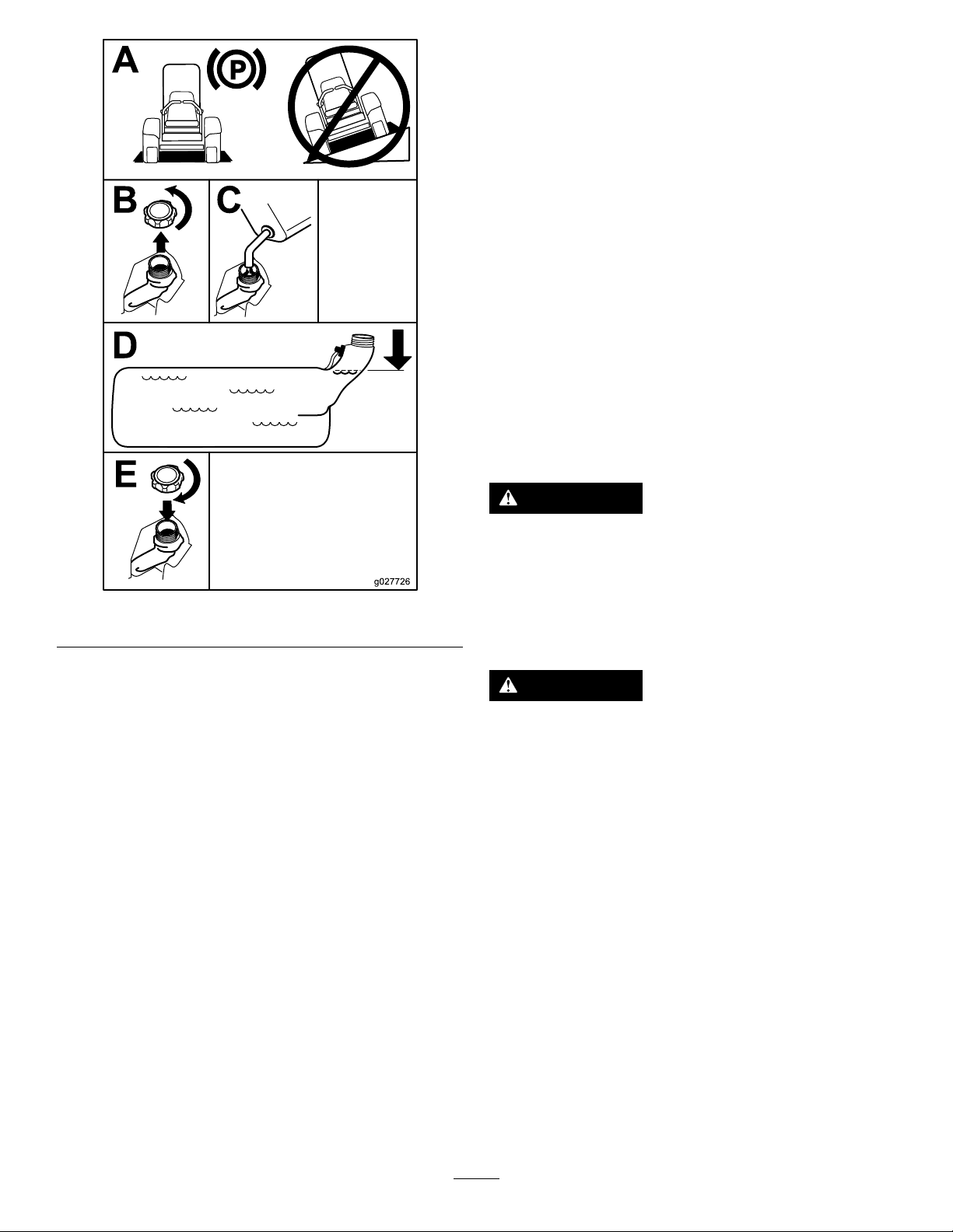
FillingtheFuelTank
1.Parkthemachineonalevelsurface.
2.Engagetheparkingbrake.
3.Shutofftheengineandremovethekey.
4.Cleanaroundthefuel-tankcap.
5.Fillthefueltanktothebottomofthellerneck
(Figure7).
Note:Donotllthefueltankcompletelyfull.
Theemptyspaceinthetankallowsthefuelto
expand.
RecommendedFuel
•Forbestresults,useonlyclean,fresh(lessthan
30daysold),unleadedgasolinewithanoctane
ratingof87orhigher((R+M)/2ratingmethod).
•Ethanol:Gasolinewithupto10%ethanol
(gasohol)or15%MTBE(methyltertiarybutyl
ether)byvolumeisacceptable.Ethanoland
MTBEarenotthesame.Gasolinewith15%
ethanol(E15)byvolumeisnotapprovedforuse.
Neverusegasolinethatcontainsmorethan
10%ethanolbyvolume,suchasE15(contains
15%ethanol),E20(contains20%ethanol),orE85
(containsupto85%ethanol).Usingunapproved
gasolinemaycauseperformanceproblemsand/or
enginedamagewhichmaynotbecoveredunder
warranty.
•Donotusegasolinecontainingmethanol.
•Donotstorefueleitherinthefueltankorfuel
containersoverthewinterunlessyouuseafuel
stabilizer.
•Donotaddoiltogasoline.
18
Page 19
PerformingDaily Maintenance
Beforestartingthemachineeachday,performthe
EachUse/DailyprocedureslistedinMaintenance
(page40).
BreakinginaNewMachine
Newenginestaketimetodevelopfullpower.Mower
decksanddrivesystemshavehigherfrictionwhen
new,placingadditionalloadontheengine.Allow
40to50hoursofbreak-intimefornewmachinesto
developfullpowerandbestperformance.
Usingthe Rollover-ProtectionSystem (ROPS)
WARNING
Figure7
Toavoidinjuryordeathfromrollover,keep
therollbarinthefullyraised,lockedposition
andusetheseatbelt.
g027726
Ensurethattheseatissecuredtothe
machine.
WARNING
Thereisnorolloverprotectionwhentheroll
barisinthedownposition.
•Lowertherollbaronlywhenabsolutely
necessary.
•Donotweartheseatbeltwhentherollbar
isinthedownposition.
•Driveslowlyandcarefully.
•Raisetherollbarassoonasclearance
permits.
•Checkcarefullyforoverheadclearances
(i.e.,branches,doorways,electricalwires)
beforedrivingunderanyobjectsanddo
notcontactthem.
19
Page 20
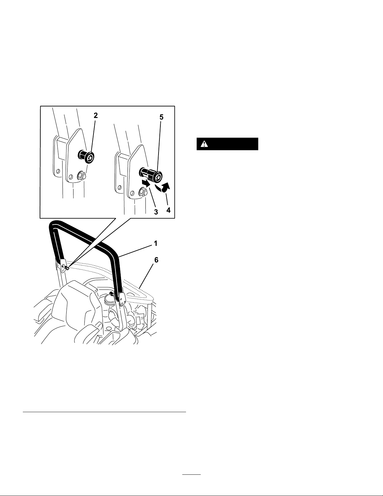
LoweringtheRollBar
Important:Lowertherollbaronlywhen
absolutelynecessary.
1.T olowertherollbar,applyforwardpressureto
theupperpartoftherollbar.
2.Pullbothknobsoutandrotatethem90degrees
sotheyarenotengaged(Figure8).
3.Lowertherollbartothedownposition(Figure
8).
1.Raisetherollbartotheoperatingpositionand
rotatetheknobsuntiltheymovepartiallyinto
thegrooves(Figure8).
2.Raisetherollbartothefulluprightpositionwhile
pushingontheupperrollbarsothatthepins
snapintopositionwhentheholesalignwiththe
pins(Figure8).
3.Pushontherollbarandensurethatbothpins
areengaged.
UsingtheSafety-Interlock System
WARNING
Ifthesafety-interlockswitchesare
disconnectedordamaged,themachinecould
operateunexpectedly,causingpersonal
injury.
•Donottamperwiththeinterlockswitches.
Figure8
1.Rollbarintheupright
position
2.ROPSknobinthelatched
position
3.PulltheROPSknobout.6.Rollbarinthefolded
4.RotatetheROPSknob90
degrees.
5.ROPSknobinthe
unlatchedposition
position
•Checktheoperationoftheinterlock
switchesdailyandreplaceanydamaged
switchesbeforeoperatingthemachine.
Understandingthe Safety-InterlockSystem
Thesafety-interlocksystemisdesignedtopreventthe
enginefromstartingunless:
•Theparkingbrakeisengaged.
•Theblade-controlswitch(PTO)isdisengaged.
•Themotion-controlleversareintheNEUTRAL-LOCK
position.
Thesafety-interlocksystemalsoisdesignedtoshut
offtheenginewhenthemotion-controlleversare
g228804
movedfromtheNEUTRAL-LOCKpositionwiththe
parkingbrakeengagedorifyourisefromtheseat
whenthePTOisengaged.
Thehourmeterhassymbolstonotifytheuserwhen
theinterlockcomponentisinthecorrectposition.
Whenthecomponentisinthecorrectposition,a
trianglelightsupinthecorrespondingsquare.
RaisingtheRollBar
Important:Alwaysusetheseatbeltwiththeroll
barintheraisedposition.
20
Page 21

Figure9
1.Triangleslightupwhentheinterlockcomponentsareinthe
correctposition
TestingtheSafety-Interlock System
ServiceInterval:Beforeeachuseordaily
Testthesafety-interlocksystembeforeyouusethe
machineeachtime.Ifthesafetysystemdoesnot
operateasdescribedbelow,haveanAuthorized
ServiceDealerrepairthesafetysystemimmediately .
1.Sitontheseat,engagetheparkingbrake,and
g009181
movetheblade-controlswitch(PTO)totheON
position.Trystartingtheengine;theengine
shouldnotstart.
2.Sitontheseat,engagetheparkingbrake,and
movetheblade-controlswitch(PTO)totheOFF
position.Moveeithermotion-controlleverout
oftheNEUTRAL-LOCKposition.Trystartingthe
engine;theengineshouldnotstart.Repeatfor
theothercontrollever.
3.Sitontheseat,engagetheparkingbrake,
movetheblade-controlswitch(PTO)totheOFF
position,andmovethemotion-controllevers
totheNEUTRAL-LOCKposition.Nowstartthe
engine.Whiletheengineisrunning,disengage
theparkingbrake,engagetheblade-control
switch(PTO),andriseslightlyfromtheseat;the
engineshouldshutoff.
4.Sitontheseat,engagetheparkingbrake,
movetheblade-controlswitch(PTO)totheOFF
position,andmovethemotion-controllevers
totheNEUTRAL-LOCKposition.Nowstartthe
engine.Whiletheengineisrunning,center
eithermotioncontrolandmove(forwardor
reverse);theengineshouldshutoff.Repeatfor
othermotioncontrol.
5.Sitontheseat,disengagetheparkingbrake,
movetheblade-controlswitch(PTO)totheOFF
position,andmovethemotion-controllevers
totheNEUTRAL-LOCKposition.Trystartingthe
engine;theengineshouldnotstart.
21
Page 22
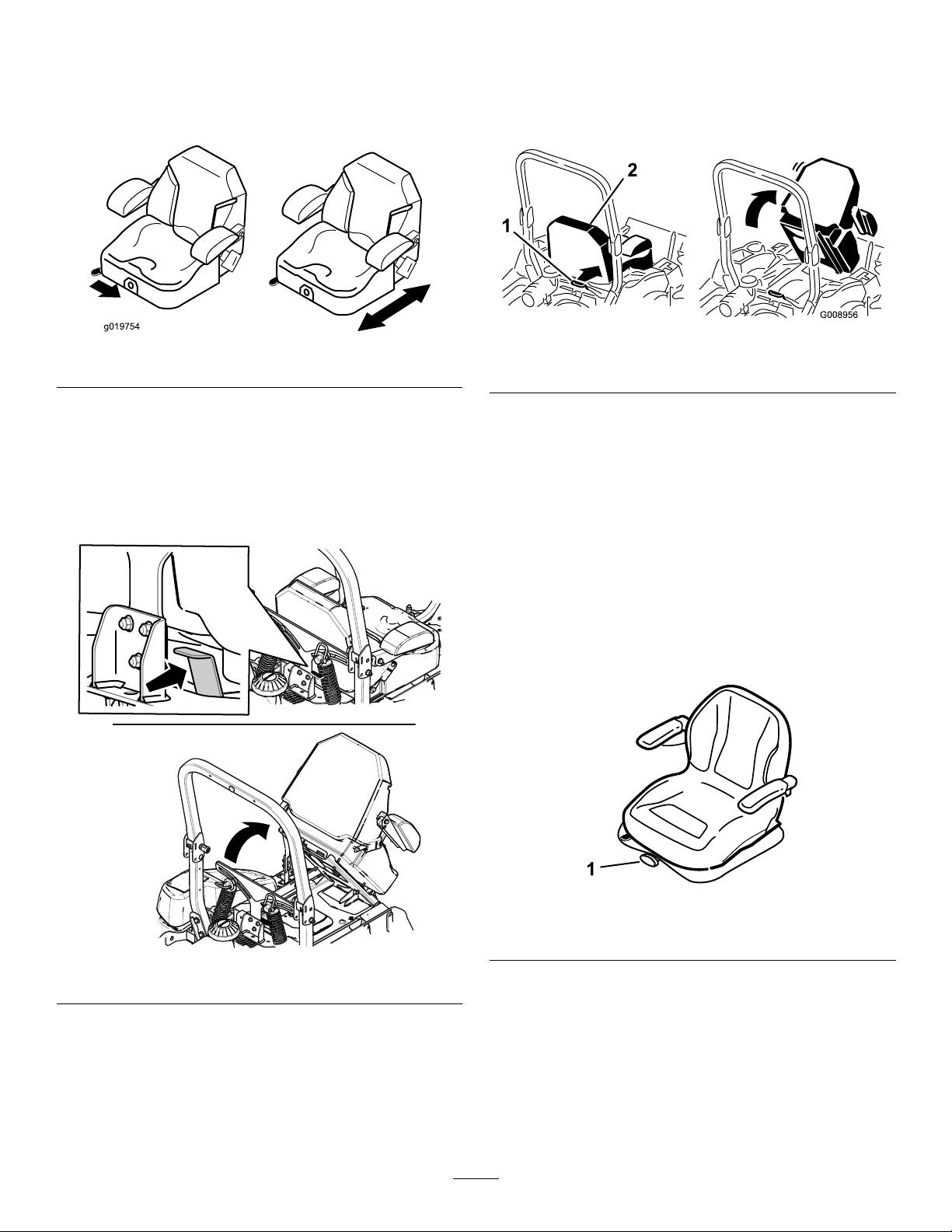
PositioningtheSeat
Theseatcanmoveforwardandbackward.Position
theseatwhereyouhavethebestcontrolofthe
machineandaremostcomfortable(Figure10).
MachineswithoutMyRide™ SuspensionSystem
Tounlatchtheseat,pushtheseatlatchforward
(Figure12).
UnlatchingtheSeat
MachineswithMyRide™ SuspensionSystem
Figure10
g019754
1.Seatlatch2.Seat
Figure12
g008956
ChangingtheSeat Suspension
MachineswithoutMyRide™
SuspensionSystemOnly
Theseatisadjustabletoprovideasmoothand
comfortableride.Positiontheseatwhereyouare
mostcomfortable.
Toadjustit,turntheknobinfronteitherdirectionto
providethebestcomfort(Figure13).
Figure11
g024881
Figure13
1.Seat-suspensionknob
g204507
22
Page 23
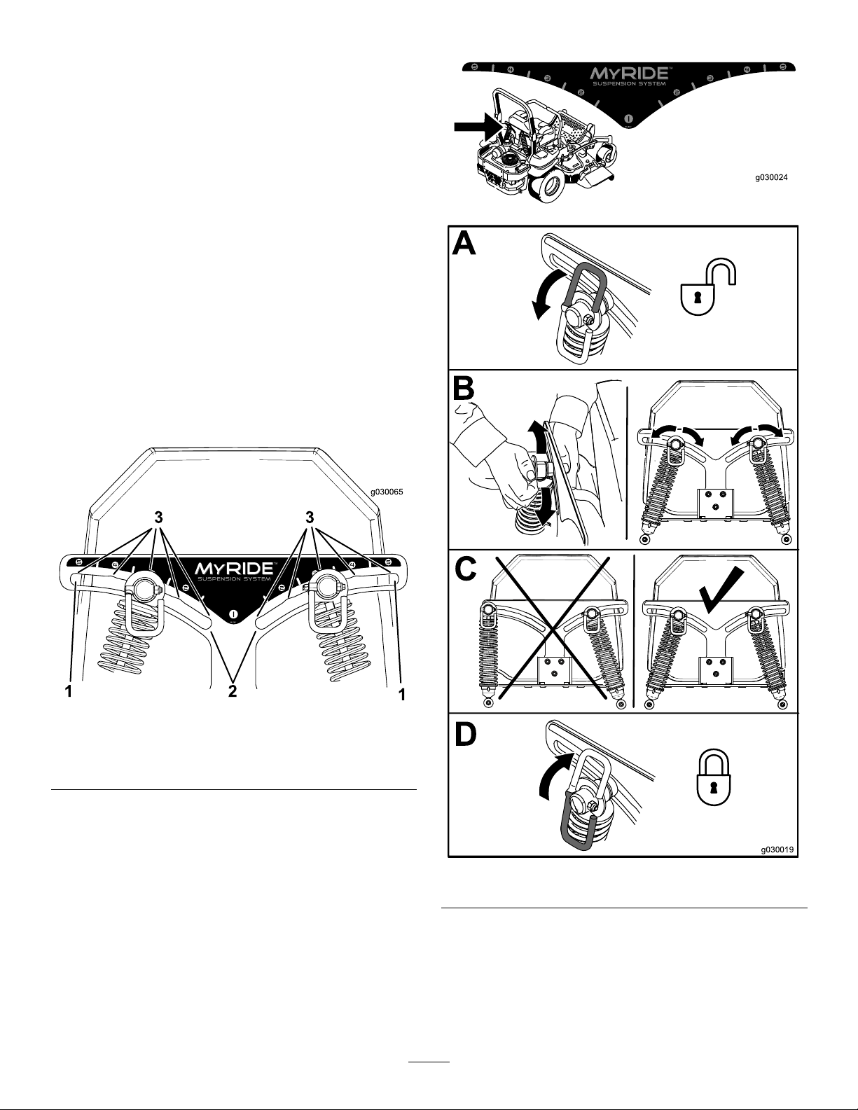
AdjustingtheMyRide™ SuspensionSystem
MachineswithMyRide™
SuspensionSystemOnly
TheMyRide™suspensionsystemadjuststoprovide
asmoothandcomfortableride.Y oucanadjustthe
rear2-shockassembliestoquicklyandeasilychange
thesuspensionsystem.Positionthesuspension
systemwhereyouaremostcomfortable.
AdjustingtheRear-Shock Assemblies
Theslotsfortherear-shockassemblieshave
detentpositionsforreference.Y oucanpositionthe
rear-shockassembliesanywhereintheslot,notjust
inthedetentpositions.
Thefollowinggraphicshowsthepositionforasoftor
rmrideandthedifferentdetentpositions(Figure14).
Adjusttherear-shockassemblies(Figure15).
g030024
Figure14
1.Firmestposition3.Detentsintheslots
2.Softestposition
Note:Ensurethattheleftandrightrear-shock
assembliesarealwaysadjustedtothesamepositions.
g030065
g030019
Figure15
23
Page 24

DuringOperation
DuringOperationSafety
GeneralSafety
•Theowner/operatorcanpreventandisresponsible
foraccidentsthatmaycausepersonalinjuryor
propertydamage.
•Wearappropriateclothing,includingeye
protection;longpants;slip-resistant,substantial
footwear;andhearingprotection.Tiebacklong
hairanddonotwearloosejewelry.
•Useyourfullattentionwhileoperatingthe
machine.Donotengageinanyactivitythat
causesdistractions;otherwise,injuryorproperty
damagemayoccur.
•Donotoperatethemachinewhileill,tired,or
undertheinuenceofalcoholordrugs.
•Nevercarrypassengersonthemachineandkeep
bystandersandpetsawayfromthemachine
duringoperation.
•Operatethemachineonlyingoodvisibilitytoavoid
holesorhiddenhazards.
•Avoidmowingonwetgrass.Reducedtraction
couldcausethemachinetoslide.
•Ensurethatalldrivesareinneutral,theparking
brakeisengaged,andyouareintheoperating
positionbeforeyoustarttheengine.
•Keepyourhandsandfeetawayfromthecutting
units.Keepclearofthedischargeopeningatall
times.
•Lookbehindanddownbeforebackinguptobe
sureofaclearpath.
•Usecarewhenapproachingblindcorners,shrubs,
trees,orotherobjectsthatmayobscureyour
vision.
•Donotmowneardrop-offs,ditches,or
embankments.Themachinecouldsuddenlyroll
overifawheelgoesovertheedgeoriftheedge
givesway.
•Stopthebladeswheneveryouarenotmowing.
•Stopthemachine,shutofftheengine,remove
thekey,andinspectthebladesafterstrikingan
objectorifthereisanabnormalvibrationinthe
machine.Makeallnecessaryrepairsbefore
resumingoperation.
•Slowdownandusecautionwhenmakingturns
andcrossingroadsandsidewalkswiththe
machine.Alwaysyieldtheright-of-way.
•Disengagethedrivetothecuttingunit,shutoffthe
engine,andremovethekeybeforeadjustingthe
heightofcut(unlessyoucanadjustitfromthe
operatingposition).
•Neverrunanengineinanareawhereexhaust
gasesareenclosed.
•Neverleavearunningmachineunattended.
•Beforeleavingtheoperatingposition(including
toemptythecatchersortounclogthechute),do
thefollowing:
–Stopthemachineonlevelground.
–Disengagethepowertakeoffandlowerthe
attachments.
–Engagetheparkingbrake.
–Shutofftheengineandremovethekey.
–Waitforallmovingpartstostop.
•Donotoperatethemachinewhenthereistherisk
oflightning.
•Donotusethemachineasatowingvehicleunless
ithasahitchinstalled.
•Donotchangethegovernorspeedoroverspeed
theengine.
•Useonlyaccessoriesandattachmentsapproved
byToro.
•Thismachineproducessoundlevelsinexcess
of85dBAattheoperator’searandcancause
hearinglossthroughextendedperiodsof
exposure.
g229846
Figure16
1.Wearhearingprotection.
RolloverProtectionSystem (ROPS)Safety
•Donotremovetherollbarfromthemachine.
•Ensurethattheseatbeltisattachedandthatyou
canreleaseitquicklyinanemergency.
•Alwayswearyourseatbeltwhentherollbarisup.
•Checkcarefullyforoverheadobstructionsanddo
notcontactthem.
•Keeptherollbarinsafeoperatingconditionby
thoroughlyinspectingitperiodicallyfordamage
andkeepingallthemountingfastenerstight.
•Replaceadamagedrollbar.Donotrepairoralter
it.
SlopeSafety
•Slopesareamajorfactorrelatedtolossofcontrol
androlloveraccidents,whichcanresultinsevere
24
Page 25
injuryordeath.Theoperatorisresponsiblefor
safeslopeoperation.Operatingthemachineon
anysloperequiresextracaution.Beforeusingthe
machineonaslope,dothefollowing:
–Reviewandunderstandtheslopeinstructions
inthemanualandonthemachine.
–Useanangleindicatortodeterminethe
approximateslopeangleofthearea.
–Neveroperateonslopesgreaterthan15
degrees.
–Evaluatethesiteconditionsofthedayto
determineiftheslopeissafeformachine
operation.Usecommonsenseandgood
judgmentwhenperformingthisevaluation.
Changesintheterrain,suchasmoisture,can
quicklyaffecttheoperationofthemachineon
aslope.
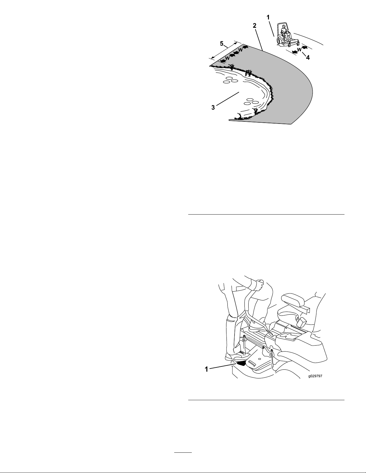
•Identifyhazardsatthebaseoftheslope.Do
notoperatethemachineneardrop-offs,ditches,
embankments,water,orotherhazards.The
machinecouldsuddenlyrolloverifawheelgoes
overtheedgeortheedgecollapses.Keepasafe
distance(twicethewidthofthemachine)between
themachineandanyhazard.Useawalk-behind
machineorahandtrimmertomowthegrassin
theseareas.
1.SafeZone—usethe
machinehereonslopes
lessthan15degreesor
atareas.
2.DangerZone—usea
walk-behindmowerand/or
ahandtrimmeronslopes
greaterthan15degrees
andneardrop-offsor
water.
3.Water
g221745
Figure17
4.W=widthofthemachine
5.Keepasafedistance
(twicethewidthofthe
machine)betweenthe
machineandanyhazard.
•Avoidstarting,stopping,orturningthemachineon
slopes.Avoidmakingsuddenchangesinspeedor
direction;turnslowlyandgradually.
•Donotoperateamachineunderanyconditions
wheretraction,steering,orstabilityisinquestion.
Beawarethatoperatingthemachineonwet
grass,acrossslopes,ordownhillmaycausethe
machinetolosetraction.Lossoftractiontothe
drivewheelsmayresultinslidingandalossof
brakingandsteering.Themachinecanslideeven
ifthedrivewheelsarestopped.
•Removeormarkobstaclessuchasditches,holes,
ruts,bumps,rocks,orotherhiddenhazards.Tall
grasscanhideobstacles.Uneventerraincould
overturnthemachine.
•Useextracarewhileoperatingwithaccessoriesor
attachments,suchasgrass-collectionsystems.
Thesecanchangethestabilityofthemachine
andcausealossofcontrol.Followdirectionsfor
counterweights.
•Ifpossible,keepthedeckloweredtotheground
whileoperatingonslopes.Raisingthedeckwhile
operatingonslopescancausethemachineto
becomeunstable.
EnteringtheOperator’s Position
Usethemowerdeckasasteptogetintothe
operator’sposition(Figure18).
g029797
Figure18
25
Page 26
OperatingtheParking
OperatingtheMower
Brake
Alwaysengagetheparkingbrakewhenyoustopthe
machineorleaveitunattended.
EngagingtheParkingBrake
Parkthemachineonalevelsurface.
Figure19
DisengagingtheParkingBrake
Blade-ControlSwitch(PTO)
Theblade-controlswitch(PTO)startsandstopsthe
mowerbladesandanypoweredattachments.
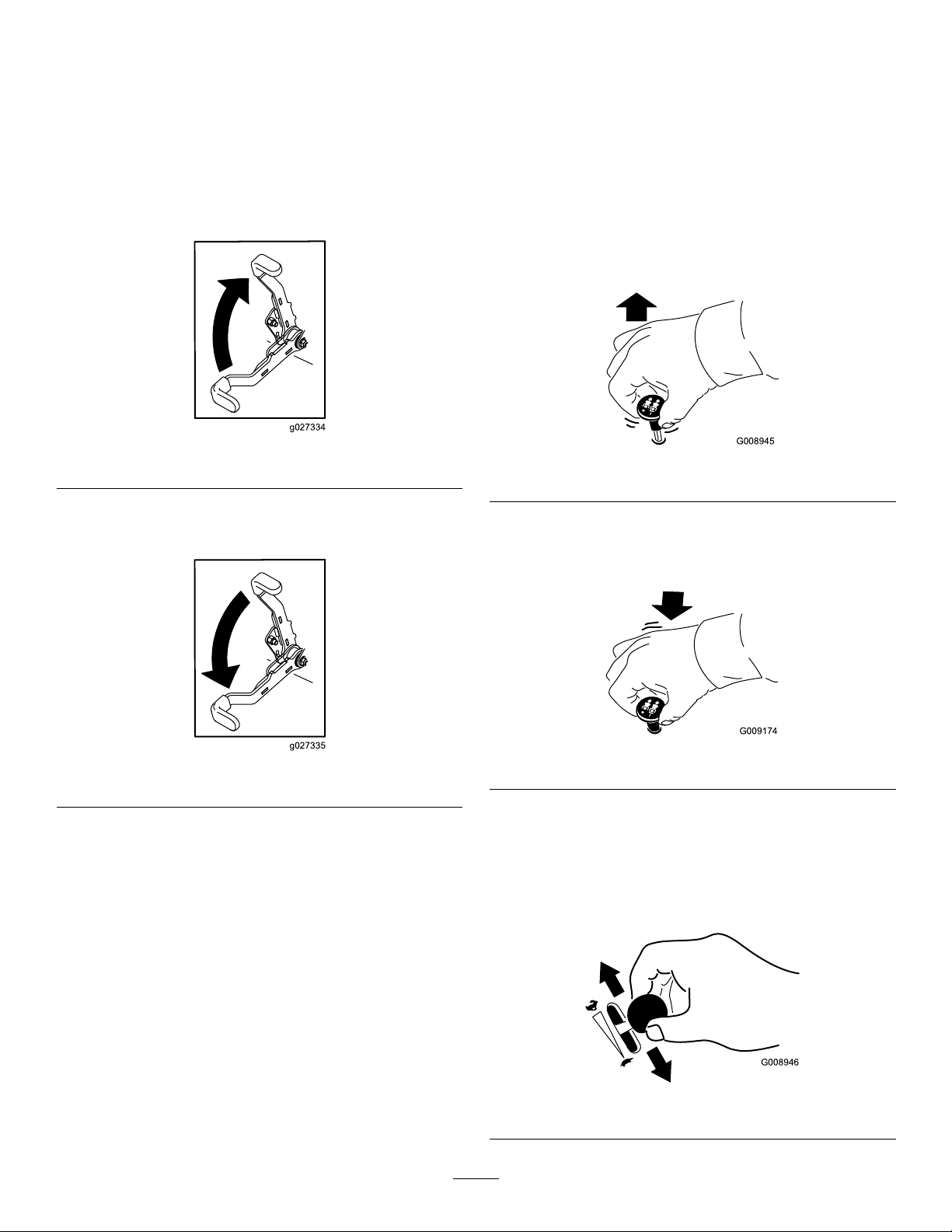
EngagingtheBlade-Control Switch(PTO)
Note:Engagingtheblade-controlswitch(PTO)with
thethrottlepositionathalforlesscausesexcessive
weartothedrivebelts.
g027334
g008945
Figure21
DisengagingtheBlade-Control
Figure20
Switch(PTO)
g009174
g027335
Figure22
OperatingtheThrottle
YoucanmovethethrottlecontrolbetweenFASTand
SLOWpositions(Figure23).
AlwaysusetheFASTpositionwhenengagingthePTO.
g008946
Figure23
26
Page 27

OperatingtheChoke
StartingtheEngine
Usethechoketostartacoldengine.
1.Pullupthechokeknobtoengagethechoke
beforeusingthekeyswitch(Figure24).
2.Pushdownthechokeknobtodisengagethe
chokeaftertheenginehasstarted(Figure24).
Important:Donotengagestarterformorethan5
secondsatatime.Iftheenginefailstostart,wait
15secondsbetweenattempts.Failuretofollow
theseinstructionscanburnoutthestartermotor.
Note:Youmayneedmultipleattemptstostartthe
enginethersttimeafteraddingfueltoanemptyfuel
system.
Figure24
1.ONposition2.OFFposition
g008959
g032328
Figure25
27
Page 28

ShuttingOfftheEngine
CAUTION
Childrenorbystandersmaybeinjuredifthey
moveorattempttooperatethemachinewhile
itisunattended.
Alwaysremovethekeyandengagethe
parkingbrakewhenleavingthemachine
unattended.
UsingtheMotion-Control Levers
Figure26
Important:Makesurethatthefuel-shutoffvalve
isclosedbeforetransportingorstoringthe
machine,asfuelleakagemayoccur.Engagethe
parkingbrakebeforetransporting.Makesurethat
youremovethekeyasthefuelpumpmayrunand
causethebatterytolosecharge.
g004532
Figure27
1.Motion-control
lever—NEUTRAL-LOCK
position
2.Center,unlockedposition5.Frontofmachine
3.Forward
4.Backward
DrivingtheMachine
g027337
Thedrivewheelsturnindependently,poweredby
hydraulicmotorsoneachaxle.Youcanturn1side
inreversewhileyouturntheotherforward,causing
themachinetospinratherthanturn.Thisgreatly
improvesthemachinemaneuverabilitybutmay
requiresometimeforyoutoadapttohowitmoves.
Thethrottlecontrolregulatestheenginespeedas
measuredinrpm(revolutionsperminute).Place
thethrottlecontrolintheFASTpositionforbest
performance.Alwaysoperateinthefullthrottle
positionwhenmowing.
28
Page 29

WARNING
Themachinecanspinveryrapidly.You
maylosecontrolofthemachineandcause
personalinjuryordamagetothemachine.
•Usecautionwhenmakingturns.
•Slowthemachinedownbeforemaking
sharpturns.
DrivingForward
Note:Theengineshutsoffwhenyoumovethe
traction-controlwiththeparkingbrakeengaged.
Tostopthemachine,pullthemotion-controllevers
totheNEUTRALposition.
1.Disengagetheparkingbrake;referto
DisengagingtheParkingBrake(page26).
2.Movetheleverstothecenter,unlockedposition.
3.T ogoforward,slowlypushthemotion-control
leversforward(Figure28).
DrivingBackward
1.Movetheleverstothecenter,unlockedposition.
2.T ogobackward,slowlypullthemotion-control
leversrearward(Figure29).
Figure28
g008953
Figure29
g008952
29
Page 30

UsingtheSideDischarge
AdjustingtheHeightofCut
MachineswithSideDischarge
Only
Themowerhasahingedgrassdeectorthat
dispersesclippingstothesideanddowntowardthe
turf.
DANGER
Withoutagrassdeector,dischargecover,or
acompletegrass-catcherassemblymounted
inplace,youandothersareexposedtoblade
contactandthrowndebris.Contactwith
rotatingmowerblade(s)andthrowndebris
willcauseinjuryordeath.
•Neverremovethegrassdeectorfromthe
mowerdeckbecausethegrassdeector
routesmaterialdowntowardtheturf.Ifthe
grassdeectoriseverdamaged,replaceit
immediately.
•Neverputyourhandsorfeetunderthe
mowerdeck.
UsingtheTransportLock
Thetransportlockhas2positions,andisusedwith
thedeck-liftpedal.ThereisaLOCKpositionand
anUNLOCKpositionforthetransportpositionofthe
mowerdeck(Figure30).
•Nevertrytoclearthedischargearea
ormowerbladesunlessyoumovethe
blade-controlswitch(PTO)totheOFF
position,rotatethekeyswitchtotheOFF
position,andremovethekeyfromthekey
switch.
•Makesurethatthegrassdeectorisinthe
downposition.
g229103
Figure30
Transport-LockPositions
1.Transportlockknob3.UNLOCKposition—The
2.LOCKposition—The
mowerdecklocksintothe
transportposition.
30
mowerdeckdoesnotlock
intothetransportposition.
Page 31

AdjustingtheHeight-of-CutPin
AdjustingtheAnti-Scalp
Theheight-of-cutisadjustedfrom25to140mm(1
to5-1/2inches)in6mm(1/4inch)incrementsby
relocatingtheclevispinintodifferentholelocations.
1.Movethetransportlocktothelockposition.
2.Pushonthedeck-liftpedalwithyourfoot,and
raisethemowerdecktothetransportposition
(alsothe140mm(5-1/2inch)cuttingheight
position)asshowninFigure31.
3.T oadjust,rotatethepin90degreesandremove
thepinfromtheheight-of-cutbracket(Figure
31).
4.Selectaholeintheheight-of-cutbracket
correspondingtotheheight-of-cutdesired,and
insertthepin(Figure31).
5.Pushonthedecklift,pullbackonthetransport
lock,andslowlylowerthemowerdeck.
Rollers
ForMachineswithSideDischarge
Wheneveryouchangetheheight-of-cut,adjustthe
heightoftheanti-scalprollers.
1.Parkthemachineonalevelsurface,disengage
theblade-controlswitch,andengagetheparking
brake.
2.Shutofftheengine,removethekey,andwait
forallmovingpartstostopbeforeleavingthe
operatingposition.
3.Adjusttheanti-scalprollersasshowninFigure
32,Figure33,andFigure34.
1.Deck-liftpedal
2.Cut-of-heightpin
Figure31
3.Transportlock
g029955
Figure32
1.Anti-scalproller4.Flangenut
2.Spacer
3.Bushing
g027343
1.Anti-scalproller3.Flangenut
2.Bushing4.Bolt
5.Bolt
g029956
Figure33
31
Page 32

Figure34
1.Anti-scalproller4.Flangenut
2.Spacer
3.Bushing
5.Bolt
AdjustingtheAnti-Scalp Rollers
ForMachineswithRearDischarge
Wheneveryouchangetheheightofcut,itis
recommendedtoadjusttheheightoftheanti-scalp
rollers.
1.Parkthemachineonalevelsurface,disengage
theblade-controlswitch,andengagetheparking
brake.
2.Shutofftheengine,removethekey,andwait
forallmovingpartstostopbeforeleavingthe
operatingposition.
g029957
g024242
Figure35
1.Flangenut3.Bushing
2.Anti-scalproller4.Bolt
3.Adjusttheanti-scalprollersasshowninFigure
35andFigure36.
g024243
Figure36
1.Bolt3.Anti-scalproller
2.Bushing4.Flangenut
32
Page 33

AdjustingtheSkid(s)
AdjustingtheFlowBafe
ForMachineswithRearDischarge
Mounttheskidsinthelowerpositionwhenoperating
inheightofcutshigherthan64mm(2-1/2inches)and
inthehigherpositionwhenoperatinginheightofcuts
lowerthan64mm(2-1/2inches).
Note:Whentheskidsbecomeworn,switchtheskid
totheoppositesidesofthemower,ippingthem
over.Thisallowsyoutousetheskidslongerbefore
replacingthem.
1.Parkthemachineonalevelsurface,disengage
theblade-controlswitch,andengagetheparking
brake.
2.Shutofftheengine,removethekey,andwait
forallmovingpartstostopbeforeleavingthe
operatingposition.
3.Removethecarriageboltsandnutsfromeach
skid(Figure37).
CamLocks
ForMachineswithSideDischarge
Thisprocedureisapplicableonlytomachineswiththe
ow-bafelocks.Certainmodelshavenutsandbolts
inplaceoftheow-bafelocksandcanbeadjusted
thesame.
Youcanadjustthemower-dischargeowfordifferent
typesofmowingconditions.Positionthecamlocks
andbafetogivethebestqualityofcut.
1.Parkthemachineonalevelsurface,disengage
theblade-controlswitch,andengagetheparking
brake.
2.Shutofftheengine,removethekey,andwait
forallmovingpartstostopbeforeleavingthe
operatingposition.
3.T oadjustthecamlocks,swingtheleverupto
loosenthecamlock(Figure38).
4.Adjustthebafeandcamlocksintheslotsto
thedesireddischargeow.
5.Swingtheleverbackovertotightenthebafe
andcamlocks(Figure38).
Figure37
1.Carriagebolt
2.Skid
4.Moveeachskidtothedesiredpositionand
securethemwiththecarriageboltsandnuts.
3.Nut
Note:Onlyusethetoporcentersetsofholes
toadjusttheskids.Thebottomholesareused
whenswitchingsidesonthemowerdeck,at
whichtimetheybecomethetopholesonthe
othersideofthemower.
5.T opreventdamagingtheskid,torquethe
carriageboltsandnutsforeachskidto12.4to
14.7N∙m(110to130in-lb).
6.Ifthecamlocksdonotlockthebafeintoplace
oritistootight,loosentheleverandthenrotate
thecamlock.
Note:Adjustthecamlockuntilthedesired
lockingpressureisachieved.
g024244
g027727
Figure38
33
Page 34

PositioningtheFlowBafe
ForMachineswithSideDischarge
Thefollowingguresareonlyrecommendations
foruse.Adjustmentsvarybygrasstype,moisture
content,andtheheightofthegrass.
Note:Iftheenginepowerdrawsdownandthe
mowergroundspeedisthesame,openupthebafe.
PositionA
Thisisthefullrearposition.Thesuggestedusefor
thispositionisasfollows:
•Short,lightgrassmowingconditions
•Dryconditions
PositionB
Usethispositionwhenbagging.Alwaysalignitwith
thebloweropening.
•Smallergrassclippings
•Propelsgrassclippingsfartherawayfromthe
mower
Figure39
g005833
Figure40
PositionC
Thisisthefullopenposition.Thesuggestedusefor
thispositionisasfollows:
•Tall,densegrassmowingconditions
•Wetconditions
•Lowerstheengine-powerconsumption
g005832
•Allowsincreasedgroundspeedinheavyconditions
g005834
Figure41
34
Page 35

OperatingTips
UsingtheFastThrottleSetting
dropontoyourlawn.Toavoidthis,moveontoa
previouslycutareawiththebladesengagedoryou
candisengagethemowerdeckwhilemovingforward.
Forbestmowingandmaximumaircirculation,operate
theengineattheFASTposition.Airisrequiredto
thoroughlycutgrassclippings,sodonotsetthe
height-of-cutsolowastototallysurroundthemower
deckinuncutgrass.Alwaystrytohave1sideofthe
mowerdeckfreefromuncutgrass,whichallowsair
tobedrawnintothemowerdeck.
CuttingaLawnfortheFirstTime
Cutgrassslightlylongerthannormaltoensurethat
thecuttingheightofthemowerdeckdoesnotscalp
anyunevenground.However,thecuttingheight
usedinthepastisgenerallythebestonetouse.
Whencuttinggrasslongerthan15cm(6inches)tall,
youmaywanttocutthelawntwicetoensurean
acceptablequalityofcut.
CuttingaThirdoftheGrassBlade
Itisbesttocutonlyaboutathirdofthegrassblade.
Cuttingmorethanthatisnotrecommendedunless
grassissparse,oritislatefallwhengrassgrows
moreslowly.
KeepingtheUndersideofthe
MowerDeckClean
Cleanclippingsanddirtfromtheundersideofthe
mowerdeckaftereachuse.Ifgrassanddirtbuildup
insidethemowerdeck,cuttingqualitywilleventually
becomeunsatisfactory.
MaintainingtheBlade(s)
Maintainasharpbladethroughoutthecuttingseason
becauseasharpbladecutscleanlywithouttearingor
shreddingthegrassblades.T earingandshredding
turnsgrassbrownattheedges,whichslowsgrowth
andincreasesthechanceofdisease.Checkthe
mowerbladesaftereachuseforsharpness,and
foranywearordamage.Filedownanynicksand
sharpenthebladesasnecessary .Ifabladeis
damagedorworn,replaceitimmediatelywitha
genuineT ororeplacementblade.
AfterOperation
AlternatingtheMowingDirection
Alternatethemowingdirectiontokeepthegrass
standingstraight.Thisalsohelpsdisperseclippings,
whichenhancesdecompositionandfertilization.
MowingatCorrectIntervals
Grassgrowsatdifferentratesatdifferenttimesof
theyear.Tomaintainthesamecuttingheight,mow
moreofteninearlyspring.Asthegrassgrowthrate
slowsinmidsummer,mowlessfrequently .Ifyou
cannotmowforanextendedperiod,rstmowata
highcuttingheight,thenmowagain2dayslaterata
lowerheightsetting.
UsingaSlowerCuttingSpeed
Toimprovecutquality,useaslowergroundspeed
incertainconditions.
AvoidingCuttingTooLow
Whenmowinguneventurf,raisethecuttingheight
toavoidscalpingtheturf.
StoppingtheMachine
AfterOperationSafety
GeneralSafety
•Cleangrassanddebrisfromthecuttingunits,
mufers,andenginecompartmenttohelpprevent
res.Cleanupoilorfuelspills.
•Shutoffthefuelandremovethekeybeforestoring
ortransportingthemachine.
•Disengagethedrivetotheattachmentwhenever
youaretransportingornotusingthemachine.
•Allowtheenginetocoolbeforestoringthemachine
inanyenclosure.
•Neverstorethemachineorfuelcontainerwhere
thereisanopename,spark,orpilotlight,such
asonawaterheateroronotherappliances.
UsingtheFuel-Shutoff Valve
Thefuel-shutoffvalveislocatedundertheseat.Move
theseatforwardtoaccessit.
Closethefuel-shutoffvalvefortransport,maintenance,
andstorage.
Ifyoumuststoptheforwardmotionofthemachine
whilemowing,aclumpofgrassclippingsmay
Ensurethatthefuel-shutoffvalveisopenwhen
startingtheengine.
35
Page 36

Figure42
1.ONposition2.OFFposition
Usingthe
Drive-Wheel-Release
2.Shutofftheengine,removethekey,andwait
forallmovingpartstostopbeforeleavingthe
operatingposition.
3.Rotatetherelease-valveleversverticallytopush
themachine(Figure43).
Note:Thisallowshydraulicuidtobypassthe
pump,enablingthewheelstoturn.
4.Disengagetheparkingbrakebeforepushing
themachine.
g008948
Valves
WARNING
Handsmaybecomeentangledintherotating
drivecomponentsbelowtheenginedeck,
whichcouldresultinseriousinjury.
Shutofftheengine,removethekey,andallow
allmovingpartstostopbeforeaccessingthe
drive-wheel-releasevalves.
WARNING
Theengineandhydraulic-driveunitscan
becomeveryhot.Touchingahotengineor
hydraulic-driveunitscancausesevereburns.
Allowtheengineandhydraulic-driveunits
tocoolcompletelybeforeaccessingthe
drive-wheel-releasevalves.
Thedrive-wheel-releasevalvesarelocatedinthe
backofeachhydraulic-driveunit,undertheseat.
Figure43
1.Verticaltopushthe
machine
5.Rotatethereleasevalvelevershorizontallyto
runthemachine(Figure43).
2.Horizontaltorunthe
machine
g015123
Note:Makesurethatthereleasevalvesareinthe
fullyhorizontalpositionwhenoperatingthemachine;
otherwise,severedamagetothehydraulicsystem
canoccur.
1.Parkthemachineonalevelsurface,disengage
theblade-controlswitch,andengagetheparking
brake.
36
Page 37

TransportingtheMachine
Useaheavy-dutytrailerortrucktotransportthe
machine.Useafull-widthramp.Ensurethatthetrailer
ortruckhasallthenecessarybrakes,lighting,and
markingasrequiredbylaw.Pleasecarefullyreadall
thesafetyinstructions.Knowingthisinformationcould
helpyouorbystandersavoidinjury.Refertoyour
localordinancesfortrailerandtie-downrequirements.
WARNING
Drivingonthestreetorroadwaywithout
turnsignals,lights,reectivemarkings,ora
slow-moving-vehicleemblemisdangerous
andcanleadtoaccidents,causingpersonal
injury.
Donotdrivethemachineonapublicstreet
orroadway.
SelectingaTrailer
WARNING
Loadingamachineontoatrailerortruck
increasesthepossibilityoftip-overandcould
causeseriousinjuryordeath(Figure44).
•Useonlyafull-widthramp;donotuse
individualrampsforeachsideofthe
machine.
•Donotexceeda15-degreeanglebetween
therampandthegroundorbetweenthe
rampandthetrailerortruck.
•Ensurethatthelengthoframpisatleast4
timesaslongastheheightofthetraileror
truckbedtotheground.Thisensuresthat
rampangledoesnotexceed15degreeson
atground.
Figure44
1.Full-widthrampinstowed
position
2.Sideviewoffull-width
rampinloadingposition
3.Notgreaterthan
15degrees
4.Rampisatleast4times
aslongastheheightof
thetrailerortruckbedto
theground
5.H=heightofthetraileror
truckbedtotheground
6.Trailer
LoadingtheMachine
WARNING
Loadingamachineontoatrailerortruck
increasesthepossibilityoftip-overandcould
causeseriousinjuryordeath.
•Useextremecautionwhenoperatinga
machineonaramp.
g027996
•Backthemachineuptherampanddriveit
forwarddowntheramp.
•Avoidsuddenaccelerationordeceleration
whiledrivingthemachineonarampas
thiscouldcausealossofcontrolora
tip-oversituation.
37
Page 38

1.Ifusingatrailer,connectittothetowingvehicle
andconnectthesafetychains.
2.Ifapplicable,connectthetrailerbrakesand
lights.
UsingtheZStand
TM
TheZStandraisesthefrontendofthemachineto
allowyoutocleanthemowerandremovetheblades.
3.Lowertheramp,ensuringthattheangle
betweentherampandthegrounddoesnot
exceed15degrees(Figure44).
4.Backthemachineuptheramp(Figure45).
Figure45
1.Backthemachineupthe
ramp.
2.Drivethemachineforward
downtheramp.
5.Shutofftheengine,removethekey,andengage
theparkingbrake.
6.Tiedownthemachinenearthefrontcaster
wheelsandtherearbumperwithstraps,chains,
cable,orropes(Figure46).Refertolocal
regulationsfortie-downrequirements.
WARNING
Themachinecouldfallontosomeoneand
causeseriousinjuryordeath.
•Useextremecautionwhenoperatingthe
machineontheZStand.
•UsetheZStandonlyforcleaningthe
mowerandremovingtheblades.
•DonotkeepthemachineontheZStand
g028043
forextendedperiodsoftime.
•Alwaysshutofftheengine,setthe
parkingbrake,andremovethekeybefore
performinganymaintenancetothemower.
DrivingupontotheZStand
Important:UsetheZStandonalevelsurface.
1.Raisethemowerdecktothetransportposition.
2.Removethebracketpin(Figure47).
Figure46
1.Tie-downloops
UnloadingtheMachine
1.Lowertheramp,ensuringthattheangle
betweentherampandthegrounddoesnot
exceed15degrees(Figure44).
2.Drivethemachineforwarddowntheramp
(Figure45).
g001811
Figure47
1.ZStand4.Bottomofslot
2.Bracketpin5.Latch
3.Bracket
g027338
3.Raisethelatch.
38
Page 39

4.Swingthestandfootoutfrontandslideit
towardmachine,intothebottomofslot(Figure
47andFigure48).
Figure48
DrivingofftheZStand
1.Removethechocksorblocks.
2.Raisethelatchtotheunlockedposition(Figure
49).
g001812
1.ZStand(positionedinslot)
2.Crackinsidewalkorturf
3.Latchrestingonpivottab
5.Setthefootofthestandonthegroundandrest
thelatchonthepivottab(Figure48).
6.Starttheengineandputitathalfthrottle.
Note:Forbestresults,placethefootofthe
standintotheseamsinsidewalksorintotheturf
(Figure48).
7.Drivethemachineontothestand.Stopwhen
thelatchdropsoverthetabintothelocked
position(Figure48).
8.Engagetheparkingbrakeandturnoffthe
engine.
9.Chockorblockthedrivewheels.
WARNING
Theparkingbrakemaynotholdthe
machineparkedontheZStandand
couldcausepersonalinjuryorproperty
damage.
Figure49
1.ZStand
2.Latch4.Unlockedposition
3.Lockedposition
3.Starttheengineandplaceitathalfthrottle.
Disengagetheparkingbrake.
4.Slowlydrivebackwardoffthestand.
5.Returnthestandtoitsrestposition(Figure47).
g001813
DonotparkontheZStandunlessthe
wheelsarechockedorblocked.
10.Performthemaintenance.
39
Page 40

Maintenance
RecommendedMaintenanceSchedule(s)
MaintenanceService
Interval
Aftertherst8hours
Aftertherst100hours
Aftertherst250hours
Beforeeachuseordaily
Every50hours
Every100hours
MaintenanceProcedure
•Changetheengineoil.
•Checkthewheellug-nuttorque.
•Checkthewheel-hubslotted-nuttorque.
•Checktheparkingbrakeadjustment.
•Changethehydraulicltersandhydraulicuidwhenusinganytypeofuid.
•Checkthesafetysystem.
•Checktheengine-oillevel.
•Checktheseatbelt.
•Checktherollbarknobs.
•Cleantheenginescreenandtheoilcooler.
•Checkandcleanthehydraulic-unitshrouds.
•Inspecttheblades.
•Cleanthemowerdeck.
•Cleanthesuspensionsystem.
•Checkthesparkarrester(ifequipped).
•Checkthetirepressure.
•Inspectthebeltsforcracksandwear.
•Checkthehydraulic-uidlevel.
•Lubricatethemowerdeck-liftpivots.
•Changetheengineoil(moreoftenindirtyordustyconditions).
•Replaceorcleanandgapthesparkplug.
•Checkandcleanengine-coolingnsandshrouds.
Every200hours
Every250hours
Every500hours
Yearlyorbeforestorage
•ForKawasakiengines—changetheengine-oillter(moreoftenindirtyordusty
conditions).
•ForKohlerengines—Replacethefuellter(moreoftenindusty,dirtyconditions).
•Replacetheprimaryairlter(moreoftenindustyorsandyconditions).
•Checkthesafetyairlter.(moreoftenindustyorsandyconditions).
•ChangethehydraulicltersandhydraulicuidwhenusingMobil®1uid(more
oftenindirtyordustyconditions).
•Replacethesafetyairlter.(moreoftenindustyorsandyconditions).
•ForKawasakiengines—Replacethefuellter(moreoftenindusty,dirtyconditions).
•Checkthewheellug-nuttorque.
•Checkthewheel-hubslotted-nuttorque.
•Adjustthecaster-pivotbearing.
•Checktheparkingbrakeadjustment.
•ChangethehydraulicltersandhydraulicuidwhenusingT oro®HYPR-OIL™500
hydraulicuid(moreoftenindirtyordustyconditions).
Monthly
Yearly
•Checkthebatterycharge.
•Greasethepump-belt-idlerarm.
•Greasethefrontcasterpivots(moreoftenindirtyordustyconditions).
•Repackthefrontcaster-wheelbearings(moreoftenindirtyordustyconditions).
•Lubricatethecaster-wheelhubs.
•Paintchippedsurfaces.
•Checkallmaintenanceprocedureslistedabovebeforestorage.
Important:Refertoyourengineowner'smanualforadditionalmaintenanceprocedures.
40
Page 41

CAUTION
Ifyouleavethekeyintheswitch,someonecouldaccidentlystarttheengineandseriously
injureyouorotherbystanders.
Removethekeyfromtheswitchbeforeyouperformanymaintenance.
Pre-Maintenance
Procedures
MaintenanceSafety
•Beforerepairingthemachinedothefollowing:
–Disengagethedrives.
–Engagetheparkingbrake.
–Shutofftheengineandremovethekey.
–Disconnectthespark-plugwire.
•Parkthemachineonalevelsurface.
•Cleangrassanddebrisfromthecuttingunit,
drives,mufers,andenginetohelppreventres.
•Cleanupoilorfuelspills.
•Donotallowuntrainedpersonneltoservicethe
machine.
•Usejackstandstosupportthemachineand/or
componentswhenrequired.
•Carefullyreleasepressurefromcomponentswith
storedenergy.
ReleasingtheMower-Deck Curtain
Loosenthebottomboltofthecurtaintoreleasethe
mower-deckcurtainandaccessthetopofthemower
deck(Figure50).Tightentheboltaftermaintenance
toinstallthecurtain.
Figure50
1.Bolt
2.Curtain
g027945
•Disconnectthebatteryorremovethespark-plug
wirebeforemakinganyrepairs.Disconnectthe
negativeterminalrstandthepositiveterminal
last.Connectthepositiveterminalrstand
negativelast.
•Usecarewhencheckingtheblades.Wrapthe
blade(s)orwearthicklypaddedgloves,anduse
cautionwhenservicingthem.Onlyreplaceblades;
donotstraightenorweldthem.
•Keepyourhandsandfeetawayfrommoving
parts.Ifpossible,donotmakeadjustmentswith
theenginerunning.
•Keepallpartsingoodworkingcondition
andallhardwaretightened,especiallythe
blade-attachmentbolts.Replaceallwornor
damageddecals.
•Neverinterferewiththeintendedfunctionofa
safetydeviceorreducetheprotectionprovided
byasafetydevice.Checktheirproperoperation
regularly.
•Checktheparkingbrakeoperationfrequently.
Adjustandserviceasrequired.
41
Page 42

RemovingtheSheet-Metal Guard
Lubrication
Loosenthe2frontboltsandremovethesheet-metal
guardtoaccessthemowerbeltsandspindles(Figure
51).Installthesheet-metalguardandtightenthebolts
aftermaintenance.
Figure51
1.Sheet-metalguard
2.Bolt
GreasingtheMachine
Greasemorefrequentlywhenoperatingconditions
areextremelydustyorsandy .
GreaseType:No.2lithiumormolybdenumgrease
1.Parkthemachineonalevelsurface,disengage
theblade-controlswitch,andengagetheparking
brake.
2.Shutofftheengine,removethekey,andwait
forallmovingpartstostopbeforeleavingthe
operatingposition.
3.Cleanthegreasettingswitharag.
Note:Makesurethatyouscrapeanypaintoff
thefrontofthetting(s).
4.Connectagreaseguntothetting.
5.Pumpgreaseintothettingsuntilgreasebegins
tooozeoutofthebearings.
g027946
6.Wipeupanyexcessgrease.
AddingLightOilorSpray Lubrication
ServiceInterval:Every100hours
Lubricatethedeck-liftpivots.
g017050
Figure52
42
Page 43

GreasingtheMowerDeck
ServiceInterval:Y early—Greasethepump-belt-idler
arm.
Yearly—Greasethefrontcasterpivots(more
oftenindirtyordustyconditions).
Yearly—Repackthefrontcaster-wheelbearings
(moreoftenindirtyordustyconditions).
1.Parkthemachineonalevelsurface,disengage
theblade-controlswitch,andengagetheparking
brake.
2.Shutofftheengine,removethekey,andwait
forallmovingpartstostopbeforeleavingthe
operatingposition.
3.Loosenthebottomboltholdingthemower-deck
curtaintothemowerdeck.RefertoReleasing
theMower-DeckCurtain(page41).
4.Removethesheet-metalguard.Referto
RemovingtheSheet-MetalGuard(page42).
5.Greasethemowerdeckidler-pulleypivotuntil
greasecomesoutthebottom(Figure53or
Figure54).
Figure53
MachinewithSideDischargeShown
g192516
Figure54
MachinewithRearDischargeShown
6.Greasethedrive-beltidlerarms(Figure55).
g009030
Figure55
g185957
7.Greasethedeck-beltidlerarms(reardischarge
machinesonly)asshowninFigure56.
43
Page 44

Figure56
MachineswithRearDischargeOnly
8.Installthesheet-metalguard.RefertoReleasing
theMower-DeckCurtain(page41).
Lubricatingthe Caster-WheelHubs
ServiceInterval:Yearly
1.Parkthemachineonalevelsurface,disengage
theblade-controlswitch,andengagetheparking
brake.
2.Shutofftheengine,removethekey,andwait
forallmovingpartstostopbeforeleavingthe
operatingposition.
g024207
9.Tightentheboltforthemower-deckcurtain.
RefertoReleasingtheMower-DeckCurtain
(page41).
10.Removethedustcapandadjustthecaster
pivots.
Note:Keepthedustcapoffuntilgreasingis
done.
11.Removethehexplug.
12.Threadagreasettingintothehole.
13.Pumpgreaseintothettinguntilitoozesout
aroundthetopbearing.
14.Removethegreasettinginthehole.
15.Installthehexpluganddustcap(Figure57).
g006115
Figure58
1.Sealguard2.Spacernutwithwrench
ats
3.Raisethemowerforaccess.
4.Removethecasterwheelfromthecasterforks.
5.Removethesealguardsfromthewheelhub.
6.Removeaspacernutfromtheaxleassemblyin
thecasterwheel.
Note:Thread-lockingadhesivehasbeen
appliedtolockthespacernutstotheaxle.
7.Removetheaxle(withtheotherspacernutstill
assembledtoit)fromthewheelassembly.
8.Pryoutsealsandinspectbearingsforwearor
damageandreplaceifnecessary.
9.Packthebearingswithageneral-purpose
grease.
10.Insert1bearingand1newsealintothewheel.
Figure57
16.Greasethecaster-wheelbearings(Figure57).
Note:Replacetheseals.
11.Iftheaxleassemblyismissingbothspacernuts,
applyathread-lockingadhesiveto1spacernut
andthreaditontotheaxlewiththewrenchats
facingoutward.
g027339
Note:Donotthreadthespacernutallof
thewayontotheendoftheaxle.Leave
approximately3mm(1/8inch)fromtheouter
44
Page 45

surfaceofthespacernuttotheendoftheaxle
insidethenut.
12.Inserttheassemblednutandaxleintothewheel
onthesideofthewheelwiththenewsealand
bearing.
13.Withtheopenendofthewheelfacingup,ll
theareainsidethewheelaroundtheaxlefullof
general-purposegrease.
14.Insertthesecondbearingandnewsealintothe
wheel.
15.Applyathread-lockingadhesivetothesecond
spacernut,andthreaditontotheaxlewiththe
wrenchatsfacingoutward.
16.T orquethenutto8to9N∙m(75to80in-lb),
loosen,thentorqueto2to3N∙m(20to25in-lb).
EngineMaintenance
EngineSafety
•Shutofftheenginebeforecheckingtheoilor
addingoiltothecrankcase.
Note:Makesurethattheaxledoesnotextend
beyondeithernut.
17.Installthesealguardsoverthewheelhub,and
insertthewheelintothecasterfork.
18.Installthecasterboltandtightenthenutfully.
Important:Topreventsealandbearingdamage,
checkthebearingadjustmentoften.Spinthe
castertire.Thetireshouldnotspinfreely(more
than1or2revolutions)orhaveanysideplay.If
thewheelspinsfreely,adjustthetorqueonthe
spacernutuntilthereisaslightamountofdrag.
Applyanotherlayerofthread-lockingadhesive.
•Keepyourhands,feet,face,clothing,andother
bodypartsawaythemuferandotherhotsurfaces.
ServicingtheAirCleaner
ServiceInterval:Every250hours—Replacethe
primaryairlter(moreoftenindusty
orsandyconditions).
Every250hours—Checkthesafetyairlter.
(moreoftenindustyorsandyconditions).
Every500hours—Replacethesafetyairlter.
(moreoftenindustyorsandyconditions).
Note:Checktheltersmorefrequentlyifthe
operatingconditionsareextremelydustyorsandy.
RemovingtheFilters
1.Parkthemachineonalevelsurface,disengage
theblade-controlswitch(PTO),andengagethe
parkingbrake.
2.Shutofftheengine,removethekey,andwait
forallmovingpartstostopbeforeleavingthe
operatingposition.
3.Releasethelatchesontheaircleanerandpull
theair-cleanercoverofftheair-cleanerbody
(Figure59).
g001883
Figure59
1.Air-cleanerbody4.Air-cleanercover
2.Primarylter5.Safetylter
3.Latch
4.Cleantheinsideoftheair-cleanercoverwith
compressedair.
5.Gentlyslidetheprimarylteroutofthe
air-cleanerbody(Figure59).
Note:Avoidknockingthelterintothesideof
thebody.
6.Removethesafetylteronlytoreplaceit.
Important:Donotattempttocleanthe
safetylter.Ifthesafetylterisdirty,then
theprimarylterisdamaged.Replaceboth
lters.
7.Inspecttheprimarylterfordamagebylooking
intothelterwhileshiningabrightlightonthe
outsideofthelter.
45
Page 46

Note:Holesinthelterappearasbrightspots.
Ifthelterisdamaged,discardit.
ServicingtheEngineOil
InspectingtheFilters
1.Inspectthesafetylter.Ifitisdirty,replaceboth
thesafetyandprimarylters.
Important:Donotattempttocleanthe
safetylter.Ifthesafetylterisdirty,then
theprimarylterisdamaged.
2.Inspecttheprimarylterfordamagebylooking
intothelterwhileshiningabrightlightonthe
outsideofthelter.Iftheprimarylterisdirty ,
bent,ordamaged,replaceit.
Note:Holesinthelterappearasbrightspots.
Donotcleantheprimarylter.
InstallingtheFilters
Important:Topreventenginedamage,always
operatetheenginewithbothairltersandthe
coverinstalled.
1.Ifyouareinstallingnewlters,checkeachlter
forshippingdamage.
Engine-OilSpecications
OilType::Detergentoil(APIserviceSF,SG,SH,SJ
orSL)
EngineOilCapacity:
•Model74902TE,74919TE,75969TE:2.0L(68
oz)withthelter;1.8L(61oz)withoutthelter
•Model74925TE,74942TE:2.3L(78oz)witha
lterchange;2.1L(71oz)withoutalterchange
Viscosity:Refertothetablebelow.
Note:Donotuseadamagedlter.
2.Ifyouarereplacingtheinnerlter,carefullyslide
itintothelterbody(Figure59).
3.Carefullyslidetheprimarylteroverthesafety
lter(Figure59).
Note:Ensurethattheprimarylterisfully
seatedbypushingontheouterrimwhile
installingit.
Important:Donotpressonthesoft,inside
areaofthelter.
4.Installtheair-cleanercoverandsecurethe
latches(Figure59).
g037096
Figure60
CheckingtheEngine-OilLevel
ServiceInterval:Beforeeachuseordaily
Note:Checktheoilwhentheengineiscold.
Important:Ifyouoverllorunderlltheengine
crankcasewithoilandruntheengine,youmay
damagetheengine.
1.Parkthemachineonalevelsurface,disengage
theblade-controlswitch(PTO),andengagethe
parkingbrake.
2.Shutofftheengine,removethekey,andwait
forallmovingpartstostopbeforeleavingthe
operatingposition.
Note:Ensurethattheengineiscoolsothatthe
oilhashadtimetodrainintothesump.
3.T okeepdirt,grassclippings,etc.,outofthe
engine,cleantheareaaroundtheoil-llcapand
dipstickbeforeremovingit(Figure61).
46
Page 47

Figure62
g027734
Figure61
ChangingtheEngineOil
ServiceInterval:Aftertherst8hours—Changethe
engineoil.
Every100hours—Changetheengineoil(more
oftenindirtyordustyconditions).
1.Parkthemachinesothatthedrainsideisslightly
lowerthantheoppositesidetoensurethatthe
oildrainscompletely.
2.Disengagetheblade-controlswitch(PTO)and
engagetheparkingbrake.
3.Shutofftheengine,removethekey,andwait
forallmovingpartstostopbeforeleavingthe
operatingposition.
4.Draintheoilfromtheengine(Figure62).
g194611
5.Slowlypourapproximately80%ofthespecied
oilintothellertubeandslowlyaddthe
additionaloiltobringittotheFullmark(Figure
63).
47
Page 48

Figure63
ChangingtheEngine-OilFilter
ServiceInterval:Every200hours—ForKawasaki
engines—changetheengine-oil
lter(moreoftenindirtyordusty
conditions).
1.Draintheoilfromtheengine;refertoChanging
theEngineOil(page47).
2.Changetheengine-oillter(Figure64).
g008804
g027660
6.Disposeoftheusedoilatarecyclingcenter.
g027477
Figure64
Note:Ensurethattheoil-ltergaskettouches
theengine,andthenturntheoillteranextra
3/4turn.
3.Fillthecrankcasewiththepropertypeofnew
oil;refertoChangingtheEngineOil(page47).
48
Page 49

ServicingtheSparkPlug
ServiceInterval:Every100hours
Ensurethattheairgapbetweenthecenterandside
electrodesiscorrectbeforeinstallingthesparkplug.
Useasparkplugwrenchforremovingandinstalling
thesparkplugandagappingtoolorfeelergaugeto
checkandadjusttheairgap.Installanewsparkplug
ifnecessary.
g009922
TypeofSparkPlug:NGK
®
BPR4ESorequivalent
AirGap:0.75mm(0.03inch)
RemovingtheSparkPlug
1.Shutofftheengine,removethekey,andwait
forallmovingpartstostopbeforeleavingthe
operatingposition.
2.DisengagethePTO,movethemotion-control
leverstotheNEUTRAL-LOCKposition,and
engagetheparkingbrake.
3.Removethelefthydraulic-unitshroudinthe
orderlistedwithFigure65.Thisgivesyou
accesstothefrontsparkplug.
1.Pullthistabouttothe
sideinthedirectionofthe
arrow
2.Pulltheshroudoffthis
frametabinthedirection
ofthearrow
g009919
Figure65
3.Pulltheshroudoffthis
frametabinthedirection
ofthearrow
4.Shroud
4.Removethesparkplug.
49
g008803
g027478
Figure66
Page 50

5.Installthelefthydraulic-unitshroud(Figure65).
CheckingtheSpark
CheckingtheSparkPlug
Important:Donotcleanthesparkplug(s).
Alwaysreplacethesparkplug(s)whenithasa
blackcoating,wornelectrodes,anoilylm,or
cracks.
Ifyouseelightbrownorgrayontheinsulator,the
engineisoperatingproperly.Ablackcoatingonthe
insulatorusuallymeanstheaircleanerisdirty.
Setthegapto0.75mm(0.03inch).
Figure67
Arrester
ForMachineswithaSpark
Arrester
ServiceInterval:Every50hours
WARNING
Hotexhaust-systemcomponentsmayignite
fuelvaporsevenafteryoushutofftheengine.
Hotparticlesexhaustedduringengine
operationmayigniteammablematerials,
resultinginpersonalinjuryorproperty
damage.
Donotrefuelorruntheengineunlessthe
sparkarresterisinstalled.
g206628
1.Parkthemachineonalevelsurface,disengage
thePTO,andengagetheparkingbrake.
2.Shutofftheengine,removethekey,andwait
forallmovingpartstostopbeforeleavingthe
operatingposition.
InstallingtheSparkPlug
Figure68
3.Waitforthemufertocool.
4.Ifyouseeanybreaksinthescreenorwelds,
replacethearrester.
5.Ifthescreenisplugged,removethearrester,
shakelooseparticlesoutofthearrester,and
cleanthescreenwithawirebrush(soakthe
screeninsolventifnecessary).
6.Installthearresterontheexhaustoutlet.
g027661
50
Page 51

FuelSystem
ElectricalSystem
Maintenance
ReplacingtheFuelFilter
ServiceInterval:Every200hours(moreoftenin
dusty,dirtyconditions).
Every500hours/Yearly(whichevercomesrst)
(moreoftenindusty,dirtyconditions).
Important:Installthefuellinehosesandsecure
withplastictiesthesameastheywereoriginally
installedatthefactorytokeepthefuellineaway
fromcomponentsthatcancausefuellinedamage.
Thefuellterislocatedneartheengineontheleft
frontoftheengine.
1.Parkthemachineonalevelsurface,disengage
theblade-controlswitch(PTO),andengagethe
parkingbrake.
2.Shutofftheengine,removethekey,andwait
forallmovingpartstostopbeforeleavingthe
operatingposition.
3.Allowthemachinetocooldown.
4.Closethefuel-shutoffvalveundertheseat.
5.Replacethefuellter(Figure69).
Maintenance
ElectricalSystemSafety
•Disconnectthebatterybeforerepairingthe
machine.Disconnectthenegativeterminalrst
andthepositivelast.Connectthepositiveterminal
rstandthenegativelast.
•Chargethebatteryinanopen,well-ventilated
area,awayfromsparksandames.Unplugthe
chargerbeforeconnectingordisconnectingthe
battery.Wearprotectiveclothinganduseinsulated
tools.
ServicingtheBattery
ServiceInterval:Monthly
RemovingtheBattery
WARNING
Batteryterminalsormetaltoolscouldshort
againstmetalmachinecomponentscausing
sparks.Sparkscancausethebatterygasses
toexplode,resultinginpersonalinjury.
Figure69
6.Openthefuel-shutoffvalve.
ServicingtheFuelTank
•Whenremovingorinstallingthebattery,
donotallowthebatteryterminalstotouch
anymetalpartsofthemachine.
•Donotallowmetaltoolstoshortbetween
thebatteryterminalsandmetalpartsofthe
machine.
WARNING
Incorrectlyremovingthecablesfrombattery
coulddamagethemachineandcables,
causingsparks.Sparkscancausethebattery
gassestoexplode,resultinginpersonal
injury.
g008963
•Alwaysdisconnectthenegative(black)
batterycablebeforedisconnectingthe
positive(red)cable.
•Alwaysconnectthepositive(red)battery
cablebeforeconnectingthenegative
(black)cable.
Donotattempttodrainthefueltank.Ensurethatan
AuthorizedServiceDealerdrainsthefueltankand
servicesanycomponentsofthefuelsystem.
1.Parkthemachineonalevelsurface,disengage
theblade-controlswitch(PTO),andengagethe
parkingbrake.
51
Page 52

2.Shutofftheengine,removethekey,andwait
forallmovingpartstostopbeforeleavingthe
operatingposition.
3.RemovethebatteryasshowninFigure70.
ChargingtheBattery
WARNING
Chargingthebatteryproducesgassesthat
canexplode.
Neversmokenearthebatteryandkeepsparks
andamesawayfromthebattery.
Important:Alwayskeepthebatteryfullycharged
(1.265specicgravity).Thisisespecially
importanttopreventbatterydamagewhenthe
temperatureisbelow0°C(32°F).
1.Removethebatteryfromthechassis;referto
RemovingtheBattery(page51).
2.Chargethebatteryfor10to15minutesat25to
30Aorfor30minutesat10A.
Note:Donotoverchargethebattery.
Figure70
g027728
3.Whenthebatteryisfullycharged,unplug
thechargerfromtheelectricaloutlet,then
disconnectthechargerleadsfromthebattery
posts(Figure71).
4.Installthebatteryinthemachineandconnect
thebatterycables;refertoInstallingtheBattery
(page53).
Note:Donotrunthemachinewiththebattery
disconnected;electricaldamagemayoccur.
Figure71
1.Positive(+)batterypost3.Red(+)chargerlead
2.Negative(–)batterypost4.Black(–)chargerlead
52
g000960
Page 53

InstallingtheBattery
Note:Positionthebatteryinthetraywiththeterminal
postsoppositefromthehydraulictank(Figure70).
Figure72
ServicingtheFuses
Theelectricalsystemisprotectedbyfuses.Itrequires
nomaintenance,however,ifafuseblowscheckthe
component/circuitforamalfunctionorshort.
Thefusesarelocatedontheconsoletotherightof
theseat(Figure73).
1.T oreplacethefuses,pulloutonthefuseto
removeit.
2.Installanewfuse(Figure73).
g032526
Figure73
1.Optionalaccessory(15A)4.Main(25A)
2.Charge(25A)
3.PTO(10A)
5.Console
g008966
53
Page 54

DriveSystem
Maintenance
CheckingtheSeatBelt
ServiceInterval:Beforeeachuseordaily
Inspecttheseatbeltforwear,cuts,andproper
operationoftheretractorandbuckle.Replacethe
seatbeltifitisdamaged.
CheckingtheRoll-Bar Knobs
ServiceInterval:Beforeeachuseordaily
WARNING
Toavoidinjuryordeathfromrollover,keep
therollbarinthefullyraised,lockedposition
andusetheseatbelt.
Ensurethattheseatissecuredtothe
machine.
•Checkthatboththemountinghardwareandthe
knobsareingoodworkingcondition.
•Makesurethattheknobsarefullyengagedwith
therollbarintheraisedposition.
Note:Theupperhoopoftherollbarmayneed
tobepushedforwardorpulledrearwardtofully
engagebothknobs(Figure74andFigure75).
1.Rollbarintheupright
position
2.Roll-barknobinthe
latchedposition
3.Pulltheroll-barknobout
androtateit90degrees.
g228804
Figure74
4.Rotatetheroll-barknob90
degrees.
5.Roll-barknobinthe
unlatchedposition
6.Rollbarinthefolded
position
Figure75
1.Engaged2.Partiallyengaged—donot
operatewiththerollbarin
thisposition.
54
g228981
Page 55

AdjustingtheTracking
CheckingtheTirePressure
1.Disengagetheblade-controlswitch(PTO).
2.Drivetoanopenatarea,movethe
motion-controlleverstotheNEUTRAL-LOCK
position.
3.Movethethrottlemidwaybetweenfastandslow.
4.Movebothmotion-controlleversalltheway
forwarduntiltheybothhitthestopsintheT-slot.
5.Checkwhichwaythemachinetracks.
•Ifittrackstotheright,loosentheboltsand
adjusttheleftstopplaterearwardonthe
leftT-slotuntilthemachinetracksstraight
(Figure76).
•Ifittrackstotheleft,loosentheboltsand
adjusttherightstopplaterearwardonthe
rightT-slotuntilthemachinetracksstraight
(Figure76).
6.Tightenthestopplate(Figure76).
ServiceInterval:Every50hours/Monthly(whichever
comesrst)
Maintaintheairpressureinthefrontandreartires
at90kPa(13psi).Uneventirepressurecancause
unevencut.Checkthetireswhentheyarecoldtoget
themostaccuratepressurereading.
g001055
Figure77
Figure76
Leftcontrollevershown
CheckingtheWheelLug Nuts
Checkandtorquethewheellugnutsto122to129
N∙m(90to95ft-lb).
CheckingtheWheel-Hub SlottedNut
ServiceInterval:Aftertherst100hours
Every500hours
Checkandensurethatthetorqueoftheslottednutis
286to352N∙m(211to260ft-lb).
Note:Donotuseanti-seizecompoundonwheelhub.
g010153
1.Controllever3.Stopplate
2.Bolt
55
Page 56

Figure79
g001297
Figure78
1.Slottednut
AdjustingtheCaster-Pivot Bearing
ServiceInterval:Every500hours/Yearly(whichever
comesrst)
1.Parkthemachineonalevelsurface,disengage
theblade-controlswitch(PTO),andengagethe
parkingbrake.
2.Shutofftheengine,removethekey,andwait
forallmovingpartstostopbeforeleavingthe
operatingposition.
3.Removethedustcapfromcasterandtighten
thelocknut(Figure79).
1.Springwashers
2.Locknut
g024121
3.Dustcap
UsingtheClutchShim
Somelatermodelyearunitshavebeenbuiltwith
clutchesthatcontainabrakeshim.Whentheclutch
brakehasworntothepointwheretheclutchnolonger
engagesconsistently,youcanremovetheshimto
extendtheclutchlife.
4.Tightenthelocknutuntilthespringwashersare
at,andthenbackoffa1/4turntoproperlyset
thepreloadonthebearings(Figure79).
Important:Makesurethatthespring
washersareinstalledcorrectlyasshownin
Figure79.
5.Installthedustcap(Figure79).
g010869
Figure80
1.Armature5.Brakespacer
2.Fieldshell6.Re-gapshim
3.Rotor7.Brakepole
4.Brake-mountingbolt
RemovingtheClutchShim
1.Parkthemachineonalevelsurface,disengage
theblade-controlswitch(PTO),andengagethe
parkingbrake.
56
Page 57

2.Shutofftheengine,removethekey,andwait
forallmovingpartstostopbeforeleavingthe
operatingposition.
3.Usinganaircompressor,blowoutanydebris
fromunderthebrakepoleandaroundthebrake
spacers(Figure81).
Figure81
4.Checktheconditionofthewire-harnessleads,
connectors,andterminals.
Note:Cleanorrepairasnecessary.
5.Verifythat12Vispresentattheclutchconnector
whentheblade-controlswitch(PTO)switchis
engaged.
6.Measurethegapbetweentherotorand
armature.Ifthegapisgreaterthan1mm(0.04
inch),dothefollowingsteps:
A.Loosenbothbrake-mountingbolts1/2to1
fullturnasshowninFigure82.
Note:Donotdiscardtheshimuntilthe
clutchisfunctioningproperly.
g010871
Figure83
1.Shim
C.Usingapneumaticline,blowoutanydebris
g010868
fromunderthebrakepoleandaroundthe
brakespacers.
D.T orqueeachbolt(M6x1)to12.3to13.7
N∙m(9.5to10.5ft-lb).
E.Usinga0.25mm(0.01inch)thickfeeler
gauge,verifythatagapispresentbetween
therotorandthearmaturefaceonboth
sidesofthebrakepoleasshowninFigure
84andFigure85.
Note:Duetothewaytherotorandthe
armaturefaceswear(peaksandvalleys)it
issometimesdifculttomeasurethegap
accurately.
Note:Donotremovethebrakepolefrom
theeldshell/armature.Thebrakepole
hasworntomatchthearmatureandneeds
tocontinuetomatchafteryouremovethe
shimtoensureproperbraketorque.
Figure82
1.Brake-mountingbolt
B.Usingneedle-nosepliers,orbyhand,hold
thetabandremovetheshim(Figure83).
g010872
Figure84
1.Feelergauge
g010870
57
Page 58

CoolingSystem
Maintenance
CleaningtheEngineScreen andEngine-OilCooler
1.Feelergauge
•Ifthegapislessthan0.25mm(0.01
inch),theninstalltheshim;referto
UsingtheClutchShim(page56).
•Ifthegapissufcient,proceedtothe
safetycheckinstepF.
F.Performthefollowingsafetycheck:
i.Sitontheseatandstarttheengine.
ii.Makesurethatthebladesdonot
engagewiththeblade-controlswitch
(PTO)intheOFFposition,andthat
theclutchisdisengaged.
Iftheclutchdoesnotdisengage,
installtheshimagain;refertoUsing
theClutchShim(page56).
iii.Engageanddisengagethe
blade-controlswitch(PTO)10
consecutivetimestoensurethatthe
clutchisfunctioningproperly.
Figure85
g010873
ServiceInterval:Beforeeachuseordaily
Removeanybuildupofgrass,dirt,orotherdebris
fromtheoilcoolerandtheenginescreen(Figure86).
g008804
g009191
Figure86
Removeanybuildupofgrass,dirt,orotherdebris
fromtheenginescreen.Thishelpsensureadequate
coolingandcorrectenginespeedandreducesthe
possibilityofoverheatingandmechanicaldamageto
theengine(Figure83).
58
Page 59

Cleaningthe
CheckingandCleaningthe
Engine-CoolingFinsand
Shrouds
ServiceInterval:Every100hours/Yearly(whichever
comesrst)
1.Parkthemachineonalevelsurface,disengage
theblade-controlswitch(PTO),andengagethe
parkingbrake.
2.Shutofftheengine,removethekey,andwait
forallmovingpartstostopbeforeleavingthe
operatingposition.
3.Removetheair-intakescreen,therecoilstarter,
andthefanhousing(Figure87).
4.Cleanthedebrisandgrassfromtheengine
parts.
5.Installtheair-intakescreen,therecoilstarter,
andthefanhousing(Figure87).
Hydraulic-UnitShrouds
ServiceInterval:Beforeeachuseordaily
1.Parkthemachineonalevelsurface,disengage
theblade-controlswitch(PTO),andengagethe
parkingbrake.
2.Shutofftheengine,removethekey,andwait
forallmovingpartstostopbeforeleavingthe
operatingposition.
3.Movetheseatforward.
4.Cleanthedebrisandgrassfromthe
hydraulic-unitshrouds(Figure88).
5.Positiontheseat.
g009922
Figure87
1.Engineguard4.Fanhousing
2.Engineair-intakescreen
3.Bolt
g015117
Figure88
1.Hydraulic-unitshrouds
g004218
5.Screw
59
Page 60

BrakeMaintenance
AdjustingtheParking Brake
ServiceInterval:Aftertherst100hours
Every500hoursthereafter
Note:Performthisprocedureattherecommended
serviceintervalorwhenabrakecomponenthasbeen
removedorreplaced.
1.Parkthemachineonalevelsurface,disengage
theblade-controlswitch(PTO),andengagethe
parkingbrake.
2.Shutofftheengine,removethekey,andwait
forallmovingpartstostopbeforeleavingthe
operatingposition.
3.Raisethebackofthemachineandsupportthe
machinewithjackstands.
Figure89
LeftSideShown
1.L-bracket4.Rearlinkageassembly
2.Linkagestop
3.Gap
5.Caliper
6.Wheelhub
g026961
CAUTION
Raisingthemachineforservice
ormaintenancerelyingsolelyon
mechanicalorhydraulicjackscouldbe
dangerous.Themechanicalorhydraulic
jacksmaynotbeenoughsupportormay
malfunctionallowingthemachinetofall,
whichcouldcauseinjury.
Donotrelysolelyonmechanical
orhydraulicjacksforsupport.Use
adequatejackstandsorequivalent
support.
4.Removethereartiresfromthemachine.
5.Removeanydebrisfromthebrakearea.
6.Rotatethedrive-wheelreleasehandleto
thereleasedposition;refertoUsingthe
Drive-Wheel-ReleaseValves(page36).
7.Checktoseeifthereisavisiblegapbetween
theL-bracketandthelinkagestop(Figure89).
8.Disengagetheparkingbrake,thelevershould
beinthedownposition.
9.Turnthewheelhubbyhandinbothdirections
relativetothecaliper;thewheelhubshould
movefreelybetweenthecaliper.
10.Ifagapisneededorthewheelhubdoesnot
movefreely:
A.Disengagetheparkingbrake.
B.Disconnectandne-tunetherearlinkage
assembly:
•Shortenthelinktocreateagap.
•Lengthenthelinktoallowwheelhub
movement.
C.Connecttherearlinkageassembly.
11.Engagetheparkingbrakeandcheckthegap.
12.Repeatsteps8through12untilavisiblegapis
achievedandthewheelhubrotatesfreely.
13.Repeatthisprocedureforthebrakeonthe
oppositeside.
14.Rotatethedrive-wheelreleasehandleto
theoperatingposition;refertoUsingthe
Drive-Wheel-ReleaseValves(page36).
15.Installthereartiresandtorquethelugnuts;
refertoCheckingtheWheelLugNuts(page55).
16.Removethejackstands.
60
Page 61

BeltMaintenance
InspectingtheBelts
ServiceInterval:Every50hours
Replacethebeltifitisworn.Thesignsofawornbelt
includesquealingwhilethebeltisrotating;theblades
slippingwhilecuttinggrass;andfrayededges,burn
marks,andcracksonthebelt.
ReplacingtheMowerBelt forSide-DischargeMower Decks
1.Parkthemachineonalevelsurface,disengage
theblade-controlswitch(PTO),andengagethe
parkingbrake.
2.Shutofftheengine,removethekey,andwait
forallmovingpartstostopbeforeleavingthe
operatingposition.
3.Lowerthemowertothe76mm(3inch)
height-of-cut.
4.Loosenthebottomboltholdingthemower-deck
curtaintothemowerdeck.RefertoReleasing
theMower-DeckCurtain(page41).
5.Removethesheet-metalguard.Referto
RemovingtheSheet-MetalGuard(page42).
6.Removethebeltcovers(Figure90).
Figure91
1.Clutchpulley5.Squareholeintheidler
2.Mowerbelt
3.Spring-loadedidlerpulley
4.Ratchet
12.Installthebeltguideontheidlerarm(Figure91).
13.Usingtheratchetinthesquarehole,installthe
idlerspring(Figure91).
armfortheratchet
6.Idler-greasetting
7.Beltguide
g009038
Figure90
1.Pushthetabdown2.Removethebeltcover
7.Usearatchetinthesquareholeintheidlerarm
toremovetensionontheidlerspring(Figure91).
8.Removethebeltfromthemower-deckpulleys.
9.Removethebeltguideonthespring-loaded
idlerarm(Figure91).
10.Removetheexistingbelt.
11.Installthenewbeltaroundthemowerpulleys
andtheclutchpulleyundertheengine(Figure
91).
Note:Makesurethatthespringendsare
seatedintheanchorgrooves.
14.Installthebeltcovers(Figure92).
g027729
61
Page 62

Figure92
8.Removethe3boltsholdingthemetalbeltcover
inplaceandremovethemetalbeltcover.
g027730
1.Positionthebeltcover3.Ensurethatthetabis
underthemetalcatch
2.Slidethebeltcoverunder
thesidecatches
15.Installthesheet-metalguard.RefertoRemoving
theSheet-MetalGuard(page42).
16.Tightentheboltforthemower-deckcurtain.
RefertoReleasingtheMower-DeckCurtain
(page41).
ReplacingtheMowerBelt forRear-DischargeMower Decks
ReplacingtheCounter-Rotating Belt
1.Parkthemachineonalevelsurface,disengage
theblade-controlswitch(PTO),andengagethe
parkingbrake.
g024145
Figure93
1.Idlerspring4.Idlerpulley
2.Counter-rotatingbelt5.Squareholeintheidler
armfortheratchet
3.Doublepulley
9.Usearatchetinthesquareholeintheidlerarm
toremovetensionontheidlerspring(Figure93).
10.Removethebeltfromthemowerdeckpulley
(Figure93).
11.Removethebeltfromtheremainingpulleys
(Figure93).
12.Routethenewbeltaboundthemowerpulleys.
13.Usingtheratchetinthesquarehole,removethe
tensiononthespring,andguidethenewbelt
aroundtheidlerpulley(Figure93).
2.Shutofftheengine,removethekey,andwait
forallmovingpartstostopbeforeleavingthe
operatingposition.
3.Lowerthemowertothe76mm(3inches)height
ofcut.
4.Lifttheoorpanuptogainaccesstothecenter
pulley.
5.Loosenthebottomboltholdingthemower-deck
curtaintothemowerdeck.RefertoReleasing
theMower-DeckCurtain(page41).
6.Removethesheet-metalguard.Referto
RemovingtheSheet-MetalGuard(page42).
7.Removetheplasticbeltcover(Figure94).
ReplacingtheMowerBelt
1.Parkthemachineonalevelsurface,disengage
theblade-controlswitch(PTO),andengagethe
parkingbrake.
2.Shutofftheengine,removethekey,andwait
forallmovingpartstostopbeforeleavingthe
operatingposition.
3.Lowerthemowertothe76mm(3inches)height
ofcut.
4.Loosenthebottomboltholdingthemower-deck
curtaintothemowerdeck.RefertoReleasing
theMower-DeckCurtain(page41).
62
Page 63

5.Removethesheet-metalguard.Referto
RemovingtheSheet-MetalGuard(page42).
6.Removethebeltcovers(Figure94).
Figure94
7.Removethecounter-rotatingbelt;referto
ReplacingtheCounter-RotatingBelt(page62).
8.Usearatchetinthesquareholeintheidlerarm
toremovetensionontheidlerspring(Figure95).
9.Removethebeltfromthemower-deckpulleys
andtheclutchpulley.
g027729
10.Installthenewbeltaroundthemowerpulleys
andtheclutchpulleyundertheengine(Figure
95).
Figure95
1.Clutchpulley
2.Mowerbelt
3.Spring-loadedidlerpulley7.Squareholeintheidler
4.Ensurethatthebelt-guide
tabhitsagainstthepivot
hub.
5.Beltguide
6.Spring-loadedidlerpulley
armfortheratchet
8.Spring
11.Rotateandensurethebelt-guidetabhitsagainst
thepivothub(Figure95).
12.Usingtheratchetinthesquarehole,installthe
beltaroundthespring-loadedidlerpulley(Figure
95).Seatthespringendsintheanchorgrooves.
13.Installthebeltcovers(Figure96).
g009038
63
Page 64

Figure96
g027730
g009039
Figure97
14.Installthesheet-metalguard.RefertoRemoving
theSheet-MetalGuard(page42).
15.Tightentheboltforthemower-deckcurtain.
RefertoReleasingtheMower-DeckCurtain
(page41).
ReplacingtheHydraulic Pump-DriveBelt
1.Parkthemachineonalevelsurface,disengage
theblade-controlswitch(PTO),andengagethe
parkingbrake.
2.Shutofftheengine,removethekey,andwait
forallmovingpartstostopbeforeleavingthe
operatingposition.
3.Removethemowerbelt;refertoReplacingthe
MowerBeltforSide-DischargeMowerDecks
(page61)orReplacingtheMowerBeltfor
Rear-DischargeMowerDecks(page62).
4.Raisethemachineandsupportitwithjack
stands(Figure97).
1.Idlerpulley
2.Clutchpulley6.Squareholeintheidler
3.Pump-drivebelt7.Idlerspring
4.Righthydraulic-pump
pulley
5.Lefthydraulic-pumppulley
arm
5.Usearatchetinthesquareholeintheidlerarm
toremovetheidlerspring(Figure97).
6.Unhooktheidlerspringfromtheframe(Figure
97).
7.Removethebeltfromthehydraulic-unit-drive
pulleysandtheenginepulley.
8.Installthenewbeltaroundenginepulleyand
the2drivepulleys.
9.Usingaratchetinthesquareholeintheidler
arm,installtheidlerspringtotheframe(Figure
97).
10.Installthemowerbelt;refertoReplacingthe
MowerBeltforSide-DischargeMowerDecks
(page61)orReplacingtheMowerBeltfor
Rear-DischargeMowerDecks(page62).
64
Page 65

ControlsSystem
Maintenance
Adjustingthe Control-HandlePosition
Thereare2heightpositionsforthecontrol
levers—highandlow.Removetheboltstoadjustthe
heightfortheoperator.
1.Parkthemachineonalevelsurface,disengage
theblade-controlswitch(PTO),andengagethe
parkingbrake.
2.Shutofftheengine,removethekey,andwait
forallmovingpartstostopbeforeleavingthe
operatingposition.
3.Loosentheboltsandangenutsinstalledinthe
levers(Figure98).
g009195
Figure99
4.Aligntheleversinthefront-to-rearpositionby
bringingtheleverstogethertotheNEUTRAL
position,andslidethemuntiltheyarealigned,
thentightenthebolts(Figure99).
Figure98
1.Bolt
2.Handle4.Nut
3.Controllever
5.Iftheendsofthelevershitagainsteach
other,refertoAdjustingtheMotion-Control
Neutral-LockPivot(page67).
6.Repeattoadjustthecontrollevers.
Adjustingthe Motion-ControlLinkage
Locatedoneithersideofthemachine,belowtheseat,
arethepump-controllinkages.Rotatingtheendnut
witha1/2-inchdeepsocketwrenchallowsnetuning
adjustmentssothatthemachinedoesnotmovein
neutral.Anyadjustmentsshouldbemadeforneutral
positioningonly.
g009040
WARNING
Theenginemustberunningandthedrive
wheelsturningsothatyoucanperformthe
adjustments.Contactwithmovingpartsor
hotsurfacesmaycausepersonalinjury.
Keepyourngers,hands,andclothingclear
ofrotatingcomponentsandhotsurfaces.
1.Disengagetheblade-controlswitch(PTO),move
themotion-controlleverstotheNEUTRAL-LOCK
position,andengagetheparkingbrake.
2.Shutofftheengine,removethekey,andwait
forallmovingpartstostopbeforeleavingthe
operatingposition.
3.Pushthedeck-liftpedal,andremovethe
height-of-cutpin.
4.Lowerdecktotheground.
65
Page 66

5.Raisetherearofmachineupandsupportitwith
jackstands(orequivalentsupport).
Note:Raisethemachinejusthighenoughto
allowthedrivewheelstoturnfreely .
6.Removetheelectricalconnectionfromtheseat
safetyswitch,locatedunderthebottomcushion
oftheseat.
Note:Theswitchisapartoftheseatassembly.
7.T emporarilyinstallajumperwireacrossthe
terminalsintheconnectorofthemainwire
harness.
8.Starttheengineandrunitatfullthrottleand
disengagethebrake.
Note:Beforestartingtheengine,ensurethat
theparkingbrakeisengagedandthatthe
motion-controlleversareout.Youdonothave
tobeintheseat.
9.Runthemachineforatleast5minuteswiththe
driveleversatfullforwardspeedtobringthe
hydraulicuiduptotheoperatingtemperature.
Note:Themotion-controlleversmust
beinneutralwhilemakinganynecessary
adjustments.
10.Bringthemotion-controlleversintotheNEUTRAL
position.
11.Adjustthepumpcontrolrodlengthsbyrotating
thedoublenutsontherodintheappropriate
directionuntilthewheelsslightlycreepin
reverse(Figure100).
g010187
Figure100
1.Doublenuts
12.Movethemotion-controlleverstotheREVERSE
positionandwhileapplyingslightpressureto
thelever,allowthereverse-indicatorspringsto
bringtheleversbacktoneutral.
Note:Thewheelsmuststopturningorslightly
creepinreverse.
13.Shutoffthemachine.
14.Removethejumperwirefromthewireharness
andplugtheconnectorintotheseatswitch.
15.Removethejackstands.
16.Raisethedeckandinstalltheheight-of-cutpin.
17.Checkthatthemachinedoesnotcreepin
neutralwiththeparkbrakesdisengaged.
Adjustingthe Motion-ControlDamper
Youcanadjustthetopdamper-mountingbolttoobtain
thedesiredmotion-controlleverresistance.Referto
Figure101formountingoptions.
66
Page 67

Figure101
RightMotionControlShown
1.T orquethelocknutto23N∙m(17ft-lb).Theboltmust
protrudepasttheendofthelocknutaftertorquing.
2.Mostresistance(rmestfeel)
3.Damper
4.Mediumresistance(mediumfeel)
5.Leastresistance(softestfeel)
HydraulicSystem
Maintenance
HydraulicSystemSafety
•Seekimmediatemedicalattentionifuidisinjected
intoskin.Injecteduidmustbesurgicallyremoved
withinafewhoursbyadoctor.
•Ensurethatallhydraulic-uidhosesandlinesare
ingoodconditionandallhydraulicconnections
andttingsaretightbeforeapplyingpressureto
g008620
thehydraulicsystem.
•Keepyourbodyandhandsawayfrompinhole
leaksornozzlesthatejecthigh-pressurehydraulic
uid.
•Usecardboardorpapertondhydraulicleaks.
•Safelyrelieveallpressureinthehydraulicsystem
beforeperforminganyworkonthehydraulic
system.
ServicingtheHydraulic
Adjustingthe Motion-Control Neutral-LockPivot
Youcanadjusttheangednuttoobtainthedesired
motion-controlleverresistancewhenmovingitto
theNEUTRAL-LOCKposition.SeeFigure102for
adjustmentoptions.
1.Loosenthejamnut.
2.Tightenorloosentheangednuttothedesired
feel.
•Formoreresistance,tightentheangednut.
•Forlessresistance,loosentheangednut
3.Tightenthejamnut.
System
Hydraulic-FluidSpecications
Hydraulic-FluidT ype:Toro
hydraulicuidorMobil
®
®
HYPR-OIL
115W-50.
Important:Usethespecieduid.Otheruids
coulddamagethehydraulicsystem.
EachHydraulic-SystemFluidCapacity:1.5L(52
oz)persidewithlterchange
CheckingtheHydraulicFluid
ServiceInterval:Every50hours—Checkthe
hydraulic-uidlevel.
1.Parkthemachineonalevelsurface,disengage
theblade-controlswitch(PTO),andengagethe
parkingbrake.
2.Shutofftheengine,removethekey,andwait
forallmovingpartstostopbeforeleavingthe
operatingposition.
3.Allowtheengineandthehydraulicsystemto
coolfor10minutes.
™
500
Figure102
1.Flangednut2.Jamnut
Note:Theoillevelonthedipstickisincorrect
whentheoilischeckedandthemachineishot.
4.Movetheseatforward.
g008621
5.Cleantheareaaroundthedipsticksof
hydraulic-systemreservoirs(Figure103).
6.Remove1dipstickfromthehydraulicreservoir
(Figure103).
67
Page 68

7.Wipethedipstickoffandthreadthedipstickinto
thereservoir.
8.Removethedipstickandlookattheend(Figure
103).
Important:Donotoverllthehydraulic
unitswithuid,asdamagemayoccur.Do
notrunthemachinewithuidbelowtheadd
mark.
9.Iftheuidlevelisattheaddmark,slowlypour
onlyenoughuidintothehydraulicreservoirto
raisetheleveltothefullorHline.
10.Installthedipstick.
ReplacingtheHydraulicFluidand Filters
ServiceInterval:Aftertherst250hours—Change
thehydraulicltersandhydraulic
uidwhenusinganytypeofuid.
Every250hours—Changethehydrauliclters
andhydraulicuidwhenusingMobil
(moreoftenindirtyordustyconditions).
Every500hours—Changethehydraulic
ltersandhydraulicuidwhenusingToro
HYPR-OIL
dirtyordustyconditions).
™
500hydraulicuid(moreoftenin
®
1uid
®
11.Repeattheprocedurefortheoppositedipstick.
Toreplacethehydraulicuid,theltersneedtobe
removed.Replacebothatthesametime;referto
Hydraulic-FluidSpecications(page67)fortheoil
specications.
1.Parkthemachineonalevelsurface,disengage
theblade-controlswitch,andengagetheparking
brake.
2.Shutofftheengine,removethekey,andwait
forallmovingpartstostopbeforeleavingthe
operatingposition.
3.Raisethemachineandsupportitwithjack
stands(Figure104).
Figure103
Eitherdipstickisusedinthemachine
1.Full3.H—meanshighlevel
2.Add4.Dipsticklocationsunder
seat
g015459
g008970
Figure104
1.Jackstands
4.Removeboththemowerbeltandthepump-drive
belt;refertoReplacingtheMowerBeltfor
Side-DischargeMowerDecks(page61)or
ReplacingtheMowerBeltforRear-Discharge
MowerDecks(page62),andrefertoReplacing
theHydraulicPump-DriveBelt(page64).
Note:Thispreventsoilfromgettingonthe
belts.
68
Page 69

5.Placeadrainpanunderthelter,removetheold
lter,andwipethesurfaceclean(Figure105).
MowerDeck Maintenance
LevelingtheMowerDeck
LevelingtheDeck
1.Parkthemachineonalevelsurface,disengage
theblade-controlswitch(PTO),andengagethe
parkingbrake.
2.Shutofftheengine,removethekey,andwait
forallmovingpartstostopbeforeleavingthe
operatingposition.
3.Checkthetirepressureinthedrivetires;referto
CheckingtheTirePressure(page55).
4.Positionthetransportlockinthelatching
position.
Figure105
Bottomviewofthemachine
1.Filterlocations
6.Applyathincoatofhydraulicuidtotherubber
gasketonthereplacementlter(Figure105).
7.Installthereplacementhydrauliclter.
8.Installthepump-drivebeltandthemowerbelt.
9.Removethejackstandsandlowerthemachine
(Figure104).
10.Adduidtothehydraulicreservoirandcheck
foranyleaks.
11.Cleanupanyspilleduid.
12.Starttheengineandletitrunforabout2minutes
topurgeairfromthesystem.
13.Shutofftheengineandcheckforleaks.
14.Checktheuidlevelwhiletheuidiscold.
15.Ifrequired,adduidtothehydraulicreservoir.
2.Hydrauliclter
Note:Donotoverll.
g008968
5.Pushthedeck-liftpedalallthewayforwardand
thedecklatchesatthe14cm(5-1/2inches)
transportposition(Figure106).
Figure106
1.Deck-liftpedal
2.Height-of-cutpin
3.Transportlock
g027343
6.Inserttheheight-adjustmentpinintothe7.6cm
(3inches)cutting-heightlocation.
7.Releasethetransportlockandallowthedeckto
lowertothecuttingheight.
8.Raisethedischargechute.
69
Page 70

9.Onbothsidesofthedeck,measurefromthe
levelsurfacetothefronttipoftheblade(Postion
A)asshowninFigure107.
Note:Themeasurementshouldread7.6mm
(3inches)
Figure107
1.7.6cm(3inch)atposition
Aiscorrect
2.8.3cm(3-1/4inch)at
positionBiscorrect
3.Measureherefromthe
bladetiptothehard
surface
4.MeasureatpositionAand
Bonbothsides
10.Fine-tunetheadjustmentnutonthefront
deck-liftassemblybyturningit(Figure108).
Note:T oincreasetheheight,turnthe
adjustmentnutclockwise;todecreasethe
height,turnthenutcounterclockwise.
Note:Ifthefrontdecklinksdonothaveenough
adjustmenttoachieveaccuratecutheight,the
single-pointadjustmentcanbeutilizedtogain
moreadjustment.
g009196
g027344
Figure108
1.Adjustmentnut3.Reardeckadjustment
2.Jamnut4.Frontdeckadjustment
11.Toadjustthesingle-pointsystem,loosenthe
2boltsatthebottomoftheheight-of-cutplate
(Figure109).
Note:Forrear-dischargemachines,themower
deckisattachedinthebackholesatthefactory.
RefertoFigure110.Ifneeded,usethefront
holesforfurtheradjustmentwhenlevelingthe
mowerdeck.
Figure109
1.Boltsatthebottomoftheheight-of-cutplate
70
g027345
Page 71

Note:Inmostconditions,thebackbladetip
shouldbeadjusted6.4mm(1/4inch)higher
thanthefront.
14.T orquethe2boltsto37to45N∙m(27to33ft-lb).
15.Onbothsidesofthedeck,measurefromthe
levelsurfacetothebacktipoftheblade(postion
B)asshowninFigure107.
Note:Themeasurementshouldread8.3cm
(3-1/4inches)
16.Finetunethescrewadjusterbyturningittoget
8.3mm(3-1/4inches)height(Figure108).
Toincreasetheheight,turntheadjustmentnut
clockwise;todecrease,turncounterclockwise.
Figure110
Rear-DischargeMachinesOnly
1.Mowerdeck3.Backhole
2.Fronthole
12.Ifthedeckistoolow,tightenthe
single-point-adjustmentboltbyrotatingit
clockwise.Ifthedeckistoohigh,loosen
thesingle-point-adjustmentboltbyrotatingit
counterclockwise(Figure111).
Note:Loosenortightenthesingle-point
adjustmentboltenoughtomovethe
height-of-cutplatemountingboltsatleast1/3
thelengthoftheavailabletravelintheirslots.
Thisregainssomeupanddownadjustmenton
eachofthe4decklinks.
g025558
17.Measureuntilall4sidesarethecorrectheight.
18.Tightenallofthenutsonthedeck-lift-arm
assemblies.
19.Lowerthedischargechute.
Figure111
1.Single-pointadjustmentbolt
13.Tightenthe2boltsatthebottomofthe
height-of-cutplate(Figure109).
g017036
71
Page 72

ServicingtheCutting Blades
Toensureasuperiorqualityofcut,keeptheblades
sharp.Forconvenientsharpeningandreplacement,
youmaywanttokeepextrabladesonhand.
BladeSafety
Awornordamagedbladecanbreak,andapieceof
thebladecouldbethrowntowardyouorbystanders,
resultinginseriouspersonalinjuryordeath.Tryingto
repairadamagedblademayresultindiscontinued
safetycerticationoftheproduct.
•Inspectthebladesperiodicallyforwearordamage.
•Usecarewhencheckingtheblades.Wrapthe
bladesorweargloves,andusecautionwhen
servicingtheblades.Onlyreplaceorsharpenthe
blades;neverstraightenorweldthem.
•Onmulti-bladedmachines,takecareasrotating1
bladecancauseotherbladestorotate.
BeforeInspectingorServicingthe Blades
1.Parkthemachineonalevelsurface,disengage
theblade-controlswitch(PTO),andengagethe
parkingbrake.
2.Shutofftheengine,removethekey,and
disconnectthespark-plugwiresfromthespark
plugs.
g006530
Figure112
1.Cuttingedge3.Wear/slotforming
2.Curvedarea4.Crack
CheckingforBentBlades
1.Rotatethebladesuntiltheendsfaceforward
andbackward.
2.Measurefromalevelsurfacetothecutting
edge,positionA,oftheblades(Figure1 13).
InspectingtheBlades
ServiceInterval:Beforeeachuseordaily
1.Inspectthecuttingedges(Figure112).
2.Iftheedgesarenotsharporhavenicks,remove
andsharpentheblade;refertoServicingthe
CuttingBlades(page72).
3.Inspecttheblades,especiallyinthecurvedarea.
4.Ifyounoticeanycracks,wear,oraslotforming
inthisarea,immediatelyinstallanewblade
(Figure112).
Figure113
1.Measureherefromblade
tohardsurface
3.Rotatetheoppositeendsofthebladesforward.
4.Measurefromalevelsurfacetothecuttingedge
ofthebladesatthesamepositionasinstep2
above.
2.PositionA
Note:Thedifferencebetweenthedimensions
obtainedinsteps2and4mustnotexceed3
mm(1/8inch).
Note:Ifthisdimensionexceeds3mm(1/8
inch),thebladeisbentandmustbereplaced.
g000975
72
Page 73

RemovingtheBlades
Side-DischargeMachines
Replacethebladesiftheyhitasolidobject,orifthe
bladeisoutofbalanceorbent.
1.Holdthebladeendusingaragorthicklypadded
glove.
2.Removethebladebolt,curvedwasher,and
bladefromthespindleshaft(Figure114).
g004536
Figure115
LeftandCenterSpindleShown
1.Sailareaoftheblade3.Curvedwasher
2.Blade4.Bladebolt
Figure114
1.Sailareaoftheblade3.Curvedwasher
2.Blade4.Bladebolt
Rear-DischargeMachines
Important:Therightbladeonthismowerdeckis
counter-rotatingandusesaleft-threadedblade
bolt.
Replaceabladeifithitsanobject,ifthebladeisout
ofbalance,orifthebladeisbent.T oensureoptimum
performanceandcontinuedsafetyconformanceof
themachine,usegenuineTororeplacementblades.
Replacementbladesmadebyothermanufacturers
mayresultinnonconformancewithsafetystandards.
1.Holdthebladeendusingaragorthickly-padded
glove.
2.Removetheleftandcenterbladebolt,curved
washer,andbladefromthespindleshaft(Figure
115).
3.Removetherightbladebolt(leftthreadedbolt),
curvedwasher,andbladefromthespindleshaft
(Figure115).
Note:Notethetypeofbladeandwhereeach
bladeisinstalled.SeeFigure116forthecorrect
position.
g004536
g024248
Figure116
Bladelocation
1.Frontofmowerdeck4.Counter-rotatingblade
2.Right-threadedbladebolts
3.Regularblades
5.Left-threadedbladebolt
73
Page 74

SharpeningtheBlades
1.Usealetosharpenthecuttingedgeatboth
endsoftheblade(Figure117).
Note:Maintaintheoriginalangle.
Note:Thebladeretainsitsbalanceifthesame
amountofmaterialisremovedfrombothcutting
edges.
Figure117
1.Sharpenatoriginalangle.
2.Checkthebalanceofthebladebyputtingiton
abladebalancer(Figure118).
Note:Ifthebladestaysinahorizontalposition,
thebladeisbalancedandcanbeused.
Note:Ifthebladeisnotbalanced,lesome
metalofftheendofthesailareaonly(Figure
117).
Rear-DischargeMachines
Important:Therightbladeonthismowerdeckis
counter-rotatingandusesaleft-threadedblade
bolt.UseFigure116forthecorrectplacementof
themowerblades.
1.Installtheleftandcenterblades,curved
washers,andbladeboltstothespindleshafts
(Figure115andFigure116).
Important:Thecurvedpartoftheblade
mustpointupwardtowardtheinsideofthe
mowertoensurepropercutting.
Note:Installthecurved-washerconetowards
g000552
thebolthead(Figure1 15).
2.Installtherightblade,curvedwasher,andblade
bolt(left-threadedbolt)tothespindleshaft
(Figure115andFigure116).
3.T orquethebladeboltto1 15to150N∙m(85to
110ft-lb).
RemovingtheMowerDeck
Lockoutthespring-loadeddeckarmsbeforeservicing
orremovingthemowerdeck.
WARNING
Figure118
1.Blade2.Balancer
3.Repeatthisprocedureuntilthebladeis
balanced.
InstallingtheBlades
Side-DischargeMachines
1.Installthebladeontothespindleshaft(Figure
114).
Important:Thecurvedpartoftheblade
mustpointupwardtowardtheinsideofthe
mowertoensurepropercutting.
2.Installthecurvedwasherandbladebolt(Figure
114).
Note:Installthecurved-washerconetoward
thebolthead.
3.T orquethebladeboltto1 15to150N∙m(85to
110ft-lb).
Deck-liftarmassemblieshavestoredenergy.
Removingthedeckwithoutreleasingthe
storedenergycancauseseriousinjuryor
g000553
death.
Donotattempttodisassemblethedeckfrom
thefrontframewithoutlockingoutthestored
energy.
1.Parkthemachineonalevelsurface,disengage
theblade-controlswitch(PTO),andengagethe
parkingbrake.
2.Shutofftheengine,removethekey,andwait
forallmovingpartstostopbeforeleavingthe
operatingposition.
3.Placetheheightadjustmentpininthe7.6cm(3
inch)cutting-heightlocation.
Note:Thislocksthedeck-liftarmsinthelowest
positionwhenthedeckisremovedandthe
storedenergyinthedeckspringisreleased.
4.Removethebeltcovers.
5.Liftuptheoorpanandinsertaratchetinto
thesquareholeinthedeckidler(Figure119or
Figure120).
6.Rotatethedeckidlerclockwise,liftuponthe
belt-guidetab(rear-dischargemachinesonly),
andremovethemowerbelt(Figure119or
Figure120).
74
Page 75

Side-DischargeMachines
Figure119
g009038
g024146
Figure120
Rear-DischargeMachines
1.Clutchpulley5.Squareholeintheidler
2.Mowerbelt
3.Spring-loadedidlerpulley
4.Ratchet
armfortheratchet
6.Idlergreasetting
7.Beltguide
1.Clutchpulley
2.Mowerbelt
3.Spring-loadedidlerpulley7.Squareholeintheidler
4.Ensurethatthebelt-guide
tabhitsagainstthepivot
hub.
5.Beltguide
6.Spring-loadedidlerpulley
armfortheratchet
8.Spring
7.Removeandretainthehardwareonbothsides
ofthedeckasshowninFigure121.
75
Page 76

Figure122
g015594
Figure121
1.Rightstabilizer
2.Deckstrut(rightsideshown)
3.Removetheshoulderboltandnut.
4.Removetheshoulderboltandnut.
8.Raisethedeckstrutsandsecuretheminthe
raisedposition.
9.Slidethedeckouttotherightsideofthe
machine.
ReplacingtheGrass
Deector
1.Bolt
2.Spacer6.Grassdeector
3.Locknut
4.Spring
g024670
3.Placethespacerandthespringontograss
deector.
4.Place1J-hookendofthespringbehindthe
deckedge.
5.Springinstalled
7.J-hookendofspring
Note:Makesurethat1J-hookendofthe
springisinstalledbehindthedeckedgebefore
installingtheboltasshowninFigure122.
5.Installtheboltandthenut.
6.Place1J-hookendofthespringaroundthe
grassdeector(Figure122).
Important:Thegrassdeectormustbeable
torotate.Liftthedeectoruptothefullopen
positionandensurethatitrotatesintothe
fulldownposition.
Side-DischargeMachinesOnly
WARNING
Anuncovereddischargeopeningcouldallow
themachinetothrowobjectstowardyouor
bystanders,resultinginseriousinjury.Also,
contactwiththebladecouldoccur.
Neveroperatethemachineunlessyouinstall
amulchplate,dischargedeector,orgrass
collectionsystem.
1.Removethelocknut,bolt,spring,andspacer
holdingthedeectortothepivotbrackets
(Figure122).
2.Removethedamagedorworngrassdeector
(Figure122).
76
Page 77

Cleaning
Storage
CleaningundertheMower Deck
ServiceInterval:Beforeeachuseordaily
1.Parkthemachineonalevelsurface,disengage
theblade-controlswitch(PTO),andengagethe
parkingbrake.
2.Shutofftheengine,removethekey,andwait
forallmovingpartstostopbeforeleavingthe
operatingposition.
3.RaisethemowerdecktotheTRANSPORT
position.
CleaningtheSuspension System
MachineswithMyRide™
SuspensionSystemOnly
ServiceInterval:Beforeeachuseordaily
Usecompressedairtocleanthesuspensionsystem.
Note:Donotcleantheshockassemblieswith
pressurizedwater(Figure123).
StorageSafety
•Shutofftheengine,removethekey ,waitforall
movingpartstostop,andallowthemachineto
coolbeforestoringit.
•Donotstorethemachineorfuelnearamesor
drainthefuelindoors.
•Removethekeyandstoreitinasafeplaceout
ofthereachofchildren.
CleaningandStorage
1.Disengagetheblade-controlswitch(PTO),and
engagetheparkingbrake.
2.Shutofftheengine,removethekey,andwait
forallmovingpartstostopbeforeleavingthe
operatingposition.
3.Removegrassclippings,dirt,andgrimefromthe
externalpartsoftheentiremachine,especially
theengineandhydraulicsystem.Cleandirtand
chafffromtheoutsideoftheenginecylinder
headnsandblowerhousing.
Important:Youcanwashthemachinewith
milddetergentandwater.Donotpressure
washthemachine.Avoidexcessiveuse
ofwater,especiallynearthecontrolpanel,
engine,hydraulicpumps,andmotors.
Figure123
DisposingofWaste
Engineoil,batteries,hydraulicuid,andengine
coolantarepollutantstotheenvironment.Disposeof
theseaccordingtoyourstateandlocalregulations.
4.Checktheparkingbrakeoperation;referto
OperatingtheParkingBrake(page26).
5.Servicetheaircleaner;refertoServicingtheAir
Cleaner(page45).
6.Greasethemachine;refertoLubrication(page
42).
7.Changethecrankcaseoil;refertoChangingthe
EngineOil(page47).
g195820
8.Checkthetirepressure;refertoCheckingthe
TirePressure(page55).
9.Changethehydrauliclters;refertoReplacing
theHydraulicFluidandFilters(page68).
10.Chargethebattery;refertoChargingtheBattery
(page52).
11.Scrapeanyheavybuildupofgrassanddirt
fromtheundersideofthemower,thenwashthe
mowerwithagardenhose.
Note:Runthemachinewiththeblade-control
switch(PTO)engagedandtheengineathigh
idlefor2to5minutesafterwashing.
12.Checktheconditionoftheblades;referto
ServicingtheCuttingBlades(page72).
77
Page 78

13.Preparethemachineforstoragewhennon-use
occursover30days.Preparethemachinefor
storageasfollows:
A.Addapetroleum-based
stabilizer/conditionertofuelinthe
tank.Followmixinginstructionsfrom
thestabilizermanufacturer.Donotuse
analcohol-basedstabilizer(ethanolor
methanol).
Note:Afuelstabilizer/conditionerismost
effectivewhenmixedwithfreshfueland
usedatalltimes.
B.Runtheenginetodistributeconditionedfuel
throughthefuelsystemfor5minutes.
C.Shutofftheengine,allowittocool,and
drainthefueltank.
D.Starttheengineandrunituntilitstops.
E.Disposeoffuelproperly.Recyclethefuel
accordingtolocalcodes.
Important:Donotstorefuelcontaining
stabilizer/conditionerlongerthan
thedurationrecommendedbythe
fuel-stabilizermanufacturer.
14.Removeandchecktheconditionofthespark
plug(s);refertoServicingtheSparkPlug(page
49).Withthesparkplug(s)removedfromthe
engine,pour30ml(2tablespoons)ofengine
oilintothesparkplughole.Usethestarterto
cranktheengineanddistributetheoilinsidethe
cylinder.Installthesparkplug(s).Donotinstall
thewireonthesparkplug(s).
15.Checkandtightenallbolts,nuts,andscrews.
Repairorreplaceanypartthatisdamaged.
16.Paintallscratchedorbaremetalsurfaces.Paint
isavailablefromyourAuthorizedServiceDealer.
17.Storethemachineinaclean,drygarageor
storagearea.Removethekeyfromtheswitch
andkeepitoutofreachofchildrenorother
unauthorizedusers.Coverthemachineto
protectitandkeepitclean.
78
Page 79

Troubleshooting
Problem
Thestarterdoesnotcrank.
Theenginedoesnotstart,startshard,or
failstokeeprunning.
PossibleCauseCorrectiveAction
1.Theblade-controlswitchisengaged.1.Disengagetheblade-controlswitch.
2.Theparkingbrakeisdisengaged.2.Engagetheparkingbrake.
3.Themotion-controlleversarenotin
theNEUTRAL-LOCKposition.
4.Y ouarenotsittingintheoperator’s
seat.
5.Thebatteryisdead.
6.Theelectricalconnectionsare
corrodedorloose.
7.Afuseisblown.7.Replacethefuse.
8.Arelayorswitchisdamaged.
1.Thefueltankisempty.1.Fillthefueltank.
2.Thefuel-shutoffvalveisclosed.2.Openthefuel-shutoffvalve.
3.Theoillevelinthecrankcaseislow.3.Addoiltothecrankcase.
4.Thethrottleisnotinthecorrect
position.
5.Thereisdirtinthefuellter.5.Replacethefuellter.
6.Dirt,water,orstalefuelisinfuel
system.
7.Theaircleanerisdirty.
8.Theseatswitchisnotfunctioning
properly.
9.Theelectricalconnectionsare
corroded,loose,ordamaged.
10.Therelayorswitchiswornor
damaged.
11.Thesparkplugisfouledorimproperly
gapped.
12.Thespark-plugwireisnotconnected.
3.Movethemotion-controllevers
outwardtotheNEUTRAL-LOCKposition.
4.Sitontheoperator’sseat.
5.Chargethebattery.
6.Checktheelectricalconnectionsfor
goodcontact.
8.ContactanAuthorizedServiceDealer.
4.Besurethatthethrottlecontrolis
midwaybetweentheslowandfast
positions.
6.ContactanAuthorizedServiceDealer.
7.Cleanorreplacetheair-cleaner
element.
8.Checktheseat-switchindicator.
Replacetheseatifnecessary .
9.Checktheelectricalconnections
forgoodcontact.Cleanthe
connectorterminalsthoroughlywith
electrical-contactcleaner,apply
dielectricgrease,andmakethe
appropriateconnections.
10.ContactanAuthorizedServiceDealer .
11.Adjustorreplacethesparkplug.
12.Checkthespark-plugwireconnection.
Theenginelosespower.
Theengineoverheats.
1.Theengineloadisexcessive.1.Reducethegroundspeed.
2.Theaircleanerisdirty.
3.Theoillevelinthecrankcaseislow.3.Addoiltothecrankcase.
4.Thecoolingnsandtheairpassages
abovetheengineareplugged.
5.Theventholeinthefuelcapisplugged.5.Cleanorreplacethefuelcap.
6.Thereisdirtinthefuellter.6.Replacethefuellter.
7.Thereisdirt,water,orstalefuelinthe
fuelsystem.
1.Theengineloadisexcessive.1.Reducethegroundspeed.
2.Theoillevelinthecrankcaseislow.2.Addoiltothecrankcase.
3.
Thecoolingnsandairpassages
undertheengine-blowerhousingare
plugged.
4.Theaircleanerisdirty.
5.
Dirt,water ,orstalefuelisinthefuel
system.
2.Cleantheair-cleanerelement.
4.Removetheobstructionfromthe
coolingnsandtheairpassages.
7.ContactanAuthorizedServiceDealer.
3.Removetheobstructionfromthe
coolingnsandairpassages.
4.Cleanorreplacetheair-cleaner
element.
5.ContactanAuthorizedServiceDealer
79
Page 80

Problem
PossibleCauseCorrectiveAction
Themachinepullstotheleftorright(with
leversfullyforward)
Themachinedoesnotdrive.
Themachinevibratesabnormally .
Thecuttingheightisuneven.
1.Thetrackingneedsadjustment1.Adjustthetracking.
2.Thetirepressureinthedrivetiresis
notcorrect.
1.Thebypassvalvesarenotclosedtight.1.Tightenthebypassvalves.
2.Thepumpbeltisworn,loose,or
broken.
3.Thepumpbeltisoffapulley.3.Changethebelt.
4.Theidlerspringisbrokenormissing.4.Replacethespring.
5.Thehydraulicuidlevelislowortoo
hot.
1.Thecuttingblade(s)is/arebentor
unbalanced.
2.Theblademountingboltisloose.2.Tightentheblademountingbolt.
3.Theenginemountingboltsareloose.3.Tightentheenginemountingbolts.
4.Theenginepulley ,idlerpulley,orblade
pulleyisloose.
5.Theenginepulleyisdamaged.
6.Thebladespindleisbent.
7.Themotormountislooseorworn.
1.Theblade(s)isnotsharp.1.Sharpentheblade(s).
2.Acuttingblade(s)is/arebent.2.Installanewcuttingblade(s).
3.Themowerisnotlevel.
4.Ananti-scalproller(ifapplicable)isnot
setcorrectly .
5.Theundersideofthemowerdeckis
dirty.
6.Thetirepressureisincorrect.6.Adjustthetirepressure.
7.Abladespindleisbent.
2.Adjustthetirepressureinthedrive
tires.
2.Changethebelt.
5.Addhydraulicuidtothereservoirsor
letitcooldown.
1.Installnewcuttingblade(s).
4.Tightentheappropriatepulley.
5.ContactanAuthorizedServiceDealer.
6.ContactanAuthorizedServiceDealer.
7.ContactanAuthorizedServiceDealer.
3.Levelthemowerfromside-to-sideand
front-to-rear.
4.Adjusttheanti-scalpwheelheight.
5.Cleantheundersideofthemower
deck.
7.ContactanAuthorizedServiceDealer.
Thebladesdonotrotate.
Theclutchdoesnotengage.
1.Themowerdeckbeltisdamaged,
worn,loose,orbroken.
2.Themowerdeckbeltisoffthepulley.
3.Thepumpdrivebeltisworn,loose,or
broken.
4.Theidlerspringisbrokenormissing.4.Replacethespring.
1.Thefuseisblown.
2.Thereislowvoltagesupplyatthe
clutch.
Thecoilisdamaged.
3.
4.Thereisinadequatecurrentsupply.4.Repairorreplacetheclutchlead
5.
Therotor/armatureairgapistoolarge.
1.Installanewdeckbelt.
2.Installthemowerbeltonthedeck
pulleyandchecktheidlerpulley,idler
arm,andspringforcorrectposition
andfunction.
3.Checkthebelttensionorinstallanew
belt.
1.Replacethefuse.Checkthecoil
resistance,batterycharge,charging
system,andwiringconnections,and
replacecomponentsifnecessary.
2.Checkthecoilresistance,battery
charge,chargingsystem,andwiring
connectionsandreplacepartsif
necessary.
Replacetheclutch.
3.
wireorelectricalsystem.Cleanthe
connectorcontacts.
5.Removetheshimorreplacetheclutch.
80
Page 81

Schematics
WireDiagram(Rev .A)
81
g009180
Page 82

Notes:
Page 83

CaliforniaProposition65WarningInformation
Whatisthiswarning?
Youmayseeaproductforsalethathasawarninglabellikethefollowing:
WARNING:CancerandReproductiveHarm—www.p65Warnings.ca.gov.
WhatisProp65?
Prop65appliestoanycompanyoperatinginCalifornia,sellingproductsinCalifornia,ormanufacturingproductsthatmaybesoldinorbroughtinto
California.ItmandatesthattheGovernorofCaliforniamaintainandpublishalistofchemicalsknowntocausecancer,birthdefects,and/orother
reproductiveharm.Thelist,whichisupdatedannually,includeshundredsofchemicalsfoundinmanyeverydayitems.ThepurposeofProp65isto
informthepublicaboutexposuretothesechemicals.
Prop65doesnotbanthesaleofproductscontainingthesechemicalsbutinsteadrequireswarningsonanyproduct,productpackaging,orliteraturewith
theproduct.Moreover,aProp65warningdoesnotmeanthataproductisinviolationofanyproductsafetystandardsorrequirements.Infact,the
CaliforniagovernmenthasclariedthataProp65warning“isnotthesameasaregulatorydecisionthataproductis‘safe’or‘unsafe.’”Manyofthese
chemicalshavebeenusedineverydayproductsforyearswithoutdocumentedharm.Formoreinformation,gotohttps://oag.ca.gov/prop65/faqs-view-all
AProp65warningmeansthatacompanyhaseither(1)evaluatedtheexposureandhasconcludedthatitexceedsthe“nosignicantrisklevel”;or(2)
haschosentoprovideawarningbasedonitsunderstandingaboutthepresenceofalistedchemicalwithoutattemptingtoevaluatetheexposure.
Doesthislawapplyeverywhere?
Prop65warningsarerequiredunderCalifornialawonly .ThesewarningsareseenthroughoutCaliforniainawiderangeofsettings,includingbutnot
limitedtorestaurants,grocerystores,hotels,schools,andhospitals,andonawidevarietyofproducts.Additionally,someonlineandmailorder
retailersprovideProp65warningsontheirwebsitesorincatalogs.
.
HowdotheCaliforniawarningscomparetofederallimits?
Prop65standardsareoftenmorestringentthanfederalandinternationalstandards.TherearevarioussubstancesthatrequireaProp65warning
atlevelsthatarefarlowerthanfederalactionlimits.Forexample,theProp65standardforwarningsforleadis0.5μg/day,whichiswellbelow
thefederalandinternationalstandards.
Whydon’tallsimilarproductscarrythewarning?
•ProductssoldinCaliforniarequireProp65labellingwhilesimilarproductssoldelsewheredonot.
•AcompanyinvolvedinaProp65lawsuitreachingasettlementmayberequiredtouseProp65warningsforitsproducts,butothercompanies
makingsimilarproductsmayhavenosuchrequirement.
•TheenforcementofProp65isinconsistent.
•CompaniesmayelectnottoprovidewarningsbecausetheyconcludethattheyarenotrequiredtodosounderProp65;alackofwarningsfora
productdoesnotmeanthattheproductisfreeoflistedchemicalsatsimilarlevels.
WhydoesT oroincludethiswarning?
Torohaschosentoprovideconsumerswithasmuchinformationaspossiblesothattheycanmakeinformeddecisionsabouttheproductstheybuyand
use.T oroprovideswarningsincertaincasesbasedonitsknowledgeofthepresenceofoneormorelistedchemicalswithoutevaluatingthelevelof
exposure,asnotallthelistedchemicalsprovideexposurelimitrequirements.WhiletheexposurefromToroproductsmaybenegligibleorwellwithinthe
“nosignicantrisk”range,outofanabundanceofcaution,T orohaselectedtoprovidetheProp65warnings.Moreover ,ifTorodoesnotprovidethese
warnings,itcouldbesuedbytheStateofCaliforniaorbyprivatepartiesseekingtoenforceProp65andsubjecttosubstantialpenalties.
RevA
Page 84

 Loading...