

Page 1

FormNo.3362-716RevD
ZMaster
®
G3Mowers
forInternationalZMaster
LooseParts
Usethechartbelowtoverifythatallpartshavebeenshipped.
ProcedureDescription
1
2
3
4
5
6
Nopartsrequired
Nopartsrequired
Rearwheels2Installthedrivewheels.
RolloverProtectionSystemKit(ROPS)
Seat
Seatplate
Flangenuts(3/8inch)
Spacers(3/8inch)
Seat
Flangenuts(3/8inch)
Longspacers(deluxeseatsonly)
Shortspacers(deluxeseatsonly)
®
G3Mowers
SetupInstructions
Qty.
–
–
1
1
1
8
4
1
4
2
4
Removepartsfromthecrate.
Checkthetirepressure.
InstalltheRolloverProtectionSystem
(ROPS).
Installtheseat(Modelsthathaveaxed
ornonipupseat).
Installtheseat(Modelsthathavea
TiltingorFlipUpSeat).
Use
7
8
9
10
11
12
13
14
15
Nopartsrequired
Rightcontrollever1
Leftcontrollever
Bolt(3/8x1inch)(2areassembled)
Nut(3/8inch)(2areassembled)
Carriagebolt(3/8x1-1/2inches)
Flangelocknut(3/8inch)
Aircleanercap1
Hoseclamp1
Clamp
Wingnut(1/4inch)
Batteryholddown2
Nopartsrequired
Nopartsrequired
Nopartsrequired
Number2generalpurposelithiumbase
ormolybdenumbasegrease.(Purchase
separately.)
–
1
4
4
1
1
1
2
–
–
–
1tube
Checktheseatbelt.
Installthemotioncontrollevers.
Installtheliftassistpedal.
Installtheaircleanercap.
InstallaBattery(Modelnumbersthat
endwithCPonly)
Chargethebattery.
Checktheengineoillevel.
Addfueltothemachine.
Checkthemachineforgrease.
16
©2011—TheT oro®Company
8111LyndaleAvenueSouth
Bloomington,MN55420
Nopartsrequired
Registeratwww.T oro.com.
–
Preparethesidedischargechute.
OriginalInstructions(EN)
PrintedintheUSA.
AllRightsReserved
Page 2
ProcedureDescription
Qty.
Use
17
18
Nopartsrequired
Operator’sManual
EngineOwner’sManual
Operatortrainingmaterial
Key2
1
RemovingPartsfromtheCrate
NoPartsRequired
Procedure
Removethetires,theseatandtheRolloverProtection
System(ROPS)Kitfromtheshippingcrate.
–
1
1
1
Checkthemachinebeforedeliveryto
thecustomer.
Deliveringthemachinetothecustomer.
3
RaisingtheMachineUpand
InstallingtheDriveWheels
Partsneededforthisprocedure:
2Rearwheels
Procedure
1.Removethescrewsholdingtherightangleretaining
platetothecrate.
2
CheckingtheTirePressure
NoPartsRequired
Procedure
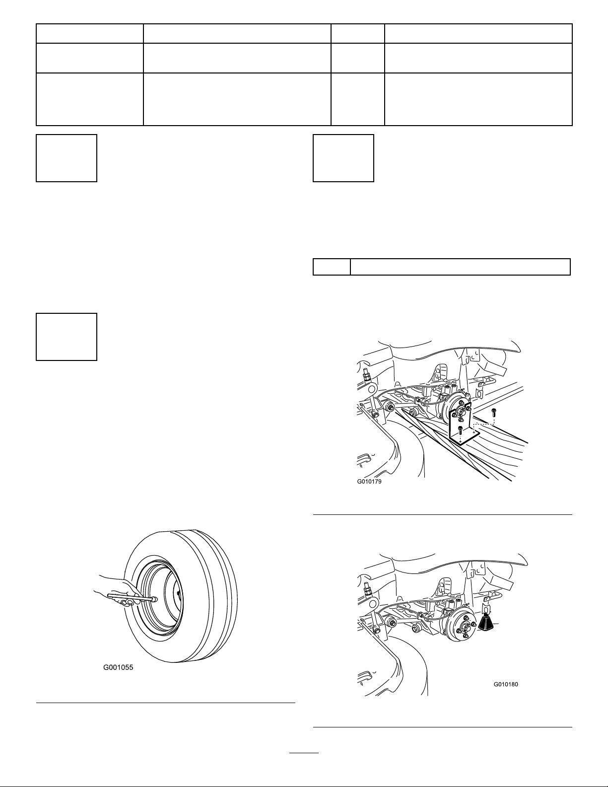
Pressure:13psi(90kPa)
Note:Thefrontcasterwheelisasemi-pneumatictire
anddoesnotneedtobechecked.
Checktheairpressureinthedrivetires.
Figure2
2.Raisethebackofthemachineupandsupportitwith
jack-stands.
Figure1
Figure3
2
Page 3
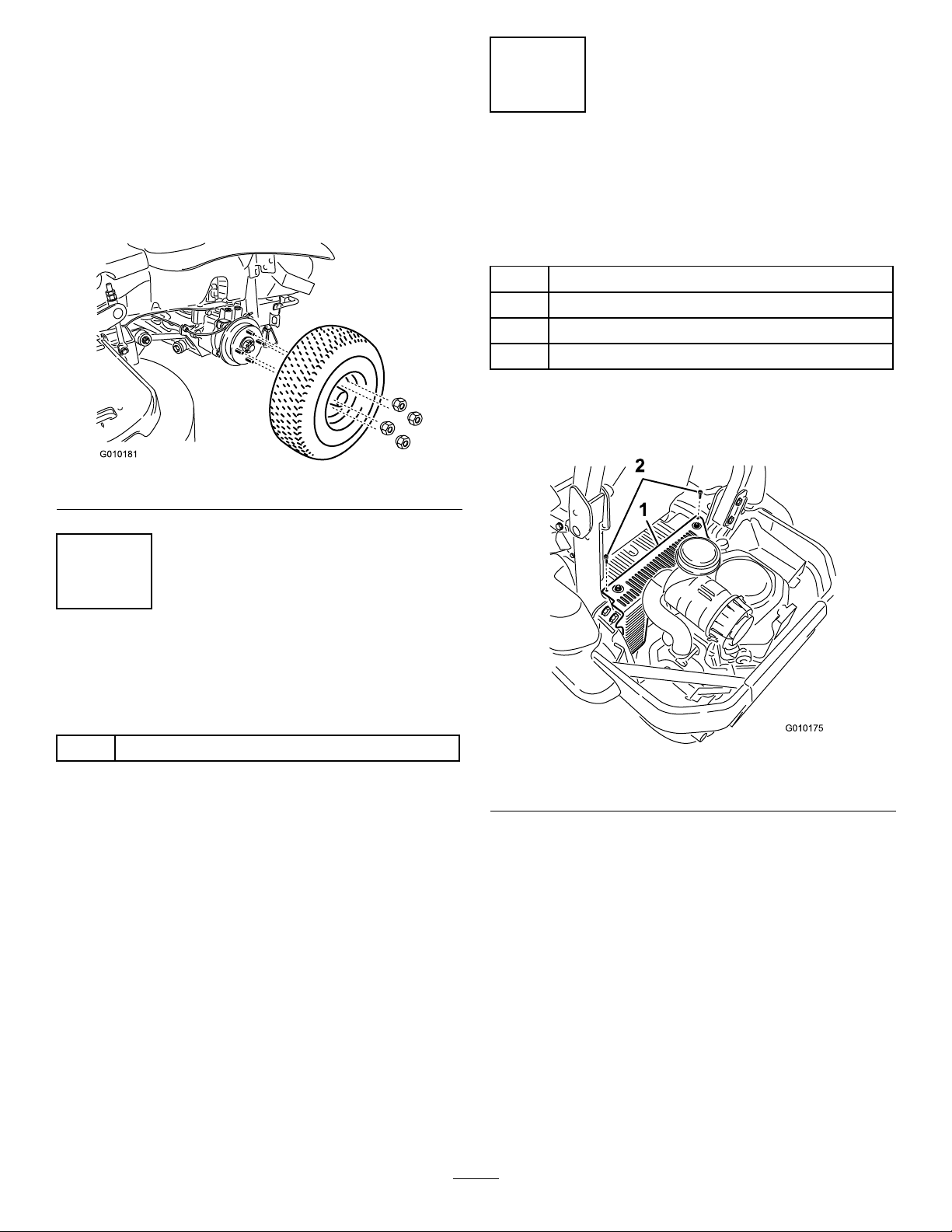
3.Removethewheelnutsfrombothsidesofthe
vehicleandremovetherightangleretainingplate.
Discardthescrewsandretainingplate.
4.Mountthewheelswiththevalvestemtotheoutside
andsecurethemwiththewheelnutspreviously
removed.
5.Torquethewheelnutsto95ft-lb(128N·m).
6.Removethejack-stands.
Figure4
5
InstallingtheSeat(Models
thathaveaxedornonipup
seat)
Partsneededforthisprocedure:
1
Seat
1
Seatplate
8
Flangenuts(3/8inch)
4
Spacers(3/8inch)
Procedure
1.Removethehydraulicunitshroudfromthemachine.
4
InstallingtheRollOver
ProtectionSystem
Partsneededforthisprocedure:
1
RolloverProtectionSystemKit(ROPS)
Procedure
InstalltheRolloverProtectionSystemKit.Followthe
instructionsincludedwiththeROPSKit.
Figure5
1.Hydraulicunitshroud2.Bolts
2.Removethe4nutsholdingtheseatplatetothe
machine.Discardthesenuts,theyareusedfor
shippingonly.
3
Page 4
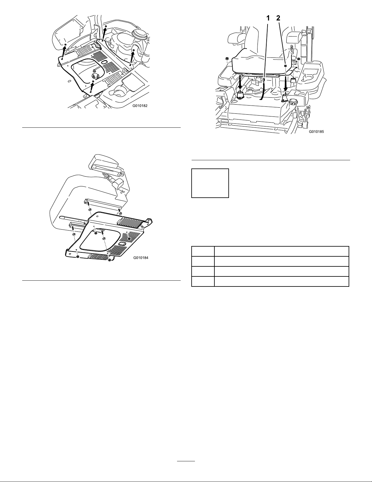
Figure6
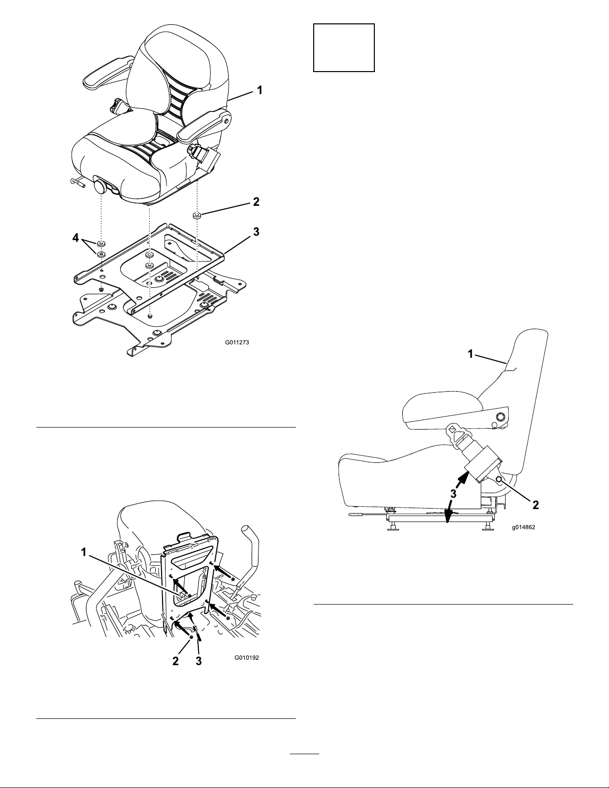
3.Securetheseatplatetotheseatwith4spacersand
4angenuts(3/8inch).
Figure7
4.Plugtheharnessconnectorintotheseatswitch
locatedundertheseattowardsthefront.
5.Installtheseattothemachineframewith4ange
nuts(3/8inch).
Figure8
1.Harnessconnector2.Flangenuts
6
InstallingtheSeat(Modelsthat
haveatiltingoripupseat)
Partsneededforthisprocedure:
1
Seat
4
Flangenuts(3/8inch)
2
Longspacers(deluxeseatsonly)
4
Shortspacers(deluxeseatsonly)
Procedure
1.Tilttheseatframeup.
2.Fordeluxeseatsonly,installthespacersasshown
inFigure9.
4
Page 5
7
3
2
1
g014862
CheckingtheSeatBelt
NoPartsRequired
Procedure
Important:Ensurethebolttorqueissetbetween
49to61ft-lb(67to83N-m).
Theseatbeltangleandtheseatbeltbolttorqueneedto
becheckedbeforeoperating.
1.Checktheangleoftheseatbeltcomparedtothe
bottomoftheseat.Theangleneedstobe47
degrees.See(Figure11)
2.Ifneeded,settheseatbelttothecorrectangle.
3.Checkandsetthebolttorquebetween49to61ft-lb
(67to83N-m).
Figure9
Formowerswithadeluxeseatonly
1.Deluxeseat
2.Longspacer
3.Seatframe
4.Shortspacers
3.Installtheseattotheseatframewith4angenuts
(3/8inch)(Figure10).
4.Plugtheharnessconnectorintotheseatswitch
locatedundertheseattowardsthefront.
1.Sideofseat
2.Seatbeltbolt,Settorque
between49to61ft-lb(67
to83N-m)
Figure11
3.47degrees
1.Seatswitch
2.Flangenuts
Figure10
3.Harnessconnector
5
Page 6

8
InstallingtheMotionControl
Levers
Partsneededforthisprocedure:
1Rightcontrollever
1
Leftcontrollever
4
Bolt(3/8x1inch)(2areassembled)
4
Nut(3/8inch)(2areassembled)
Procedure
1.Rotatethemotioncontrolleverstotheupright
position.
Figure13
2.Looselyinstallthecontrolleversontheoutsideof
theposts,using4boltsand4nuts.
Note:Installthecontrolleversinthetopand
middleholesforthehighpositionorthemiddleand
bottomholesforthelowposition,asdesired.
Figure12
1.Bolt(3/8x1inch)3.Controllever
2.Handle
4.Nut(3/8inch)
Note:Ifthemachineisnotproperlytracking,refer
toAdjustingtheTrackinginyourOperator’sManual.
9
InstallingtheLiftAssistPedal
Partsneededforthisprocedure:
1
Carriagebolt(3/8x1-1/2inches)
1
Flangelocknut(3/8inch)
Procedure
1.Ifneeded,loosentheexistingboltandnutforthe
liftassistpedal.
2.Rotatetheliftassistpedaltothecorrectposition
andinstallthecarriagebolt(3/8x1-1/2inches)and
locknut(3/8inch)(Figure14).Tightenbothbolts.
3.Raisetheleversandalignthemtogetherinthe
neutralpositionandtightenthebolts.
6
Page 7

1 2
3
g016346
Figure14
1.Liftassistpedal3.Carriagebolt(3/8x1-1/2
inches)
2.Flangelocknut(3/8inch)
10
Figure15
2.Removetheaircleanercapfromthemachine.
3.Installthehoseclampontotheaircleanercap.
Figure16
InstallingtheAirCleanerCap
Partsneededforthisprocedure:
1Aircleanercap
1Hoseclamp
Procedure
Note:Notallunitscomewithaheavydutyaircleaner.
Thisprocedureonlyappliestomodelsthathaveaheavy
dutyaircleaner.
1.Removetheplasticplugortapecoveringtheair
cleaner.
4.Installtheaircleanercapontotheaircleanerand
secureitwiththehoseclamp.
Figure17
7
Page 8

11
InstallingaBattery(Model
numbersthatendwithCP
only)
Partsneededforthisprocedure:
1
Clamp
2
Wingnut(1/4inch)
2Batteryholddown
Procedure
1.Purchasea12Vbattery.
Chargethebattery.RefertotheOperator’sManualfor
instructions.
Figure18
Modelswitha29hpengineandbelowrequirea
batterywithaminimumof260CCA.
Modelswitha30hpengineandhigherrequirea
batterywithaminimumof340CCA.
2.Locatethebatterymountinghardwareandinstallit
intothemachine.RefertoInstallingtheBatteryin
theOperator’sManual.
12
ChargingtheBattery
NoPartsRequired
Procedure
Chargingthebatteryproducesgassesthatcan
explodeandcauseseriousinjury.
•Keepcigarettes,sparksandamesaway
fromthebattery.
13
CheckingtheEngineOilLevel
NoPartsRequired
Procedure
Beforeyoustarttheengineandusethemachine,check
theoillevelintheenginecrankcase;refertoServicing
theEngineOilLevelinOperator’sManual.
14
AddingFueltotheMachine
NoPartsRequired
Procedure
Addgasolinetothemachinebeforestartingit.Refer
toyourOperator’ sManual.forthecorrectfueland
procedure.
•Makesuretheignitionswitchisoff.
•Ventilatewhenchargingorusingthebattery
inanenclosedspace.
Important:Donotrunthemachinewiththe
batterydisconnected;electricaldamagemayoccur
totheengine.
8
Page 9

G008942
1
2
4
3
Figure19
Figure20
2.Checkthegreaseforthepumpdrivebeltidlerarm.
15
CheckingtheMachinefor
Grease
Partsneededforthisprocedure:
1tube
Procedure
1.Checkthegreaseforthethreespindlebearingsand
Number2generalpurposelithiumbaseor
molybdenumbasegrease.(Purchaseseparately.)
theidlerpulley.Ifneeded,addgreaseuntilitcomes
outofthelowerseals.
Figure21
9
Page 10

16
g015594
1
6 2
4
7
3
5
CheckingtheSideDischarge
Chute
NoPartsRequired
Procedure
Ifthereareplastictiesholdingthesidedischargechute
up,removethemandlowerthechuteintoplace.
Anuncovereddischargeopeningcouldallow
thelawnmowertothrowobjectsinthe
operator’sorbystander’sdirectionandresultin
seriousinjuryordeath.Also,contactwiththe
bladecouldoccur.
Neveroperatethelawnmowerwiththegrass
deectorremovedunlessyouinstallacover
plate,amulchplate,oragrasschuteand
catcher.
1.MakesureoneJendofthespringisinstalledbehind
thedeckedgebeforeinstallingtheboltasshownin
Figure22.
2.PlaceoneJhookendofthespringaroundthegrass
deector(Figure22).
Important:Thegrassdeectormustbefreeto
rotatewithdownwardtension.Liftthedeector
uptothefullopenpositionandensurethatit
rotatesfreely,withoutbindingintothefulldown
position.
Figure22
1.Bolt
2.Spacer6.GrassDeector
3.Locknut
4.Spring
5.Springinstalled(around
thegrassdeectorand
behindthedeckedge)
7.Jhookendofspring
10
Page 11

17
CheckingtheMachineBeforeDeliverytotheCustomer
NoPartsRequired
Procedure
Beforedeliveringthemachinetothecustomer,ensurethatyouperformorhaveperformedtheprocedureslistedin
thefollowingtableandinitialeachwhennished.RefertotheOperator’sManualforinstructionsonperforming
theseprocedures.
Initial
Checkthetirepressure.
Checkthelevelofthemower.
Checkthatallmowerspindlesaregreased.
Checktheengineoillevel.
Checkthehydraulicuidlevel.
CheckROPSissecure.
Onliquidcooledmachines,checkthelevelofthecoolantintheradiatorandoverowbottle.
Checktheadjustmentoftheparkingbrake.
Ensurethatthemachinetrackscorrectly;refertotheOperator’sManualfortheadjustmentprocedure.
Checkthesafetyinterlocksystem;refertotheOperator’sManual.
EnsurethatthePTOworks.
Checkallfastenersyouinstalledtoensurethattheyaretight.
CheckProcedure
Whenyounishsettingupthemachine,signanddateinthespaceprovidedbelow:
Signature:Date:
11
Page 12

18
DeliveringtheMachinetotheCustomer
Partsneededforthisprocedure:
1
Operator’sManual
1
EngineOwner’sManual
1
Operatortrainingmaterial
2Key
Procedure
Atdelivery,Fillinthemodelandserialnumberandcompletetheitemslistedinthefollowingtableandinitial
eachwhennished.
ModelNo.SerialNo.
12
Page 13

DealerInitial
CustomerInitialCheckProcedure
Showthecustomerwherethefollowingfeaturesarelocatedandhowtheyfunction:
•
Hourmeter/SafetyInterlockSymbols/BatteryIndicator/FuelGauge
•
Fueltankcap(s)
•
Oilllcap/Oildipstick
•
Sparkplug(s)
•
Engineoillter
•
Engineoildrain
•
Fuellter(s)
•
Airlter
•
Radiatorcoolant(ifapplicable)
•
Hydraulicuidreservoir
•
Hydrauliclter
•
Battery
•
Ignitionswitch
•
Throttlelever
•
Choke(ifapplicable)
•
Powertakeoffswitch(PTO)
•
Motioncontrollevers
•
Parkingbrake
•
Mowerheight-of-cut
•
Height-of-cutdeckliftpedal/TransportLock
•
ZStand®(ifapplicable)
•
Adjustableseat
•
Hydraulicbypassvalves
•
RolloverProtectionSystem(ROPS)
•
Mowerdeckowbafe
RefertotheOperator’sManualtopointoutsafetyprocedures,operation,and
maintenanceprocedures.
ReviewthewarrantystatementasshownintheOperator’sManual.
Describethepostsaleserviceproceduresforyourstore.
Assistthecustomerinllingoutandmailingtheregistrationcardorregisteronlineat
www.T oro.com
MakesurethatthecustomerreceivestheOperator’sManual,EngineOwner’sManual,
SetUpInstructions,andoperatortrainingmaterial.
MakesurethecustomerknowsthePartsCatalogisavailableatwww.Toro.com.
Assistthecustomerinloadingthemower.
Note:Whenyou,thedealerrepresentative,havenisheddeliveringthemachinetothecustomer,signanddatein
thespaceprovidebelowandkeepacopyofthispagefordealerrecords.
Signature:
Signature:Date:
Date:
13
Page 14

Notes:
14
Page 15

Notes:
15
Page 16

 Loading...