

Toro 74876 Operator's Manual
FormNo.3425-751RevA
TimeCutter
®
HDX4850,X5450,
XS4850,orXS5450RidingMower
ModelNo.74874—SerialNo.400000000andUp
ModelNo.74876—SerialNo.400000000andUp
ModelNo.74886—SerialNo.400000000andUp
ModelNo.74888—SerialNo.400000000andUp
Registeratwww.T oro.com.
OriginalInstructions(EN)
*3425-751*A

ThisproductcomplieswithallrelevantEuropean
directives;fordetails,pleaseseetheseparateproduct
specicDeclarationofConformity(DOC)sheet.
GrossorNetTorque:Thegrossornettorque
ofthisenginewaslaboratoryratedbytheengine
manufacturerinaccordancewiththeSocietyof
AutomotiveEngineers(SAE)J1940orJ2723.As
conguredtomeetsafety,emission,andoperating
requirements,theactualenginetorqueonthisclass
ofmowerwillbesignicantlylower.Pleasereferto
theenginemanufacturer’sinformationincludedwith
themachine.
Gotowww.Toro.comtoviewspecicationsonyour
model.
Important:IfyouareusingamachinewithaToro
engineabove1500m(5,000ft)foracontinuous
period,ensurethattheHighAltitudeKithasbeen
installedsothattheenginemeetsCARB/EPA
emissionregulations.TheHighAltitudeKit
increasesengineperformancewhilepreventing
spark-plugfouling,hardstarting,andincreased
emissions.Onceyouhaveinstalledthekit,attach
thehigh-altitudelabelnexttotheserialdecalon
themachine.ContactanyAuthorizedToroService
DealertoobtaintheproperHighAltitudeKitand
high-altitudelabelforyourmachine.Tolocate
adealerconvenienttoyou,accessourwebsite
atwww.T oro.comorcontactourT oroCustomer
CareDepartmentatthenumber(s)listedinyour
EmissionControlWarrantyStatement.
Removethekitfromtheengineandrestorethe
enginetoitsoriginalfactorycongurationwhen
runningtheengineunder1500m(5,000ft).Do
notoperateanenginethathasbeenconverted
forhigh-altitudeuseatloweraltitudes;otherwise,
youcouldoverheatanddamagetheengine.
Ifyouareunsurewhetherornotyourmachine
hasbeenconvertedforhigh-altitudeuse,lookfor
thefollowinglabel.
designedprimarilyforcuttinggrassonwell-maintained
lawns.
Readthisinformationcarefullytolearnhowtooperate
andmaintainyourproductproperlyandtoavoid
injuryandproductdamage.Youareresponsiblefor
operatingtheproductproperlyandsafely .
Visitwww.Toro.comforproductsafetyandoperation
trainingmaterials,accessoryinformation,helpnding
adealer,ortoregisteryourproduct.
Wheneveryouneedservice,genuineToroparts,or
additionalinformation,contactanAuthorizedService
DealerorToroCustomerServiceandhavethemodel
andserialnumbersofyourproductready.Figure1
identiesthelocationofthemodelandserialnumbers
ontheproduct.Writethenumbersinthespace
provided.
Important:Withyourmobiledevice,youcan
scantheQRcodeontheserialnumberdecal(if
equipped)toaccesswarranty,parts,andother
productinformation.
g234368
Figure1
1.Modelandserialnumberplate
Writetheproductmodelandserialnumbersinthe
spacebelow:
decal127-9363
Introduction
Thisrotary-blade,ridinglawnmowerisintendedtobe
usedbyhomeownersinresidentialapplications.Itis
©2018—TheToro®Company
8111LyndaleAvenueSouth
Bloomington,MN55420
ModelNo.
SerialNo.
Thismanualuses2wordstohighlightinformation.
Importantcallsattentiontospecialmechanical
informationandNoteemphasizesgeneralinformation
worthyofspecialattention.
2
Contactusatwww.Toro.com.
PrintedintheUSA
AllRightsReserved

Contents
Safety.......................................................................4
SafetyAlertSymbol............................................4
GeneralSafety...................................................4
SlopeIndicator...................................................5
SafetyandInstructionalDecals..........................6
ProductOverview...................................................12
Controls...........................................................12
BeforeOperation.................................................14
BeforeOperationSafety...................................14
Pre-Start...........................................................14
FuelSafety.......................................................15
AddingFuel......................................................16
PerformingDailyMaintenance..........................16
BreakinginaNewMachine..............................16
UsingtheSafety-InterlockSystem....................17
PositioningtheSeat..........................................17
AdjustingtheMyRide™Suspension
System..........................................................18
AdjustingtheMotion-ControlLevers.................19
ConvertingtoSideDischarge...........................19
DuringOperation.................................................23
DuringOperationSafety...................................23
EnteringtheOperator’sPosition.......................25
OperatingtheParkingBrake.............................25
EngagingtheBlade-ControlSwitch
(PTO)............................................................25
DisengagingtheBlade-ControlSwitch
(PTO)............................................................26
OperatingtheThrottle.......................................26
OperatingtheChoke.........................................26
OperatingtheKeySwitch.................................27
StartingtheEngine...........................................27
ShuttingOfftheEngine.....................................28
UsingtheMotion-ControlLevers.......................28
DrivingtheMachine..........................................28
UsingtheSmartSpeed
System..........................................................29
UsingtheSmartSpeed
System..........................................................30
UsingtheSideDischarge.................................31
AdjustingtheHeightofCut...............................31
AdjustingtheAnti-ScalpRollers........................32
UsingAttachmentsandAccessories.................32
OperatingTips.................................................33
AfterOperation....................................................34
AfterOperationSafety......................................34
PushingtheMachinebyHand..........................36
Maintenance...........................................................37
MaintenanceSafety..........................................37
RecommendedMaintenanceSchedule(s)...........38
Pre-MaintenanceProcedures..............................39
ReleasingtheMower-DeckCurtain..................39
EngineMaintenance...........................................39
EngineSafety...................................................39
ServicingtheAirCleaner..................................39
ServicingtheEngineOil....................................41
TM
Control
TM
Control
ServicingtheSparkPlug...................................43
CleaningtheCoolingSystem............................44
FuelSystemMaintenance...................................45
ReplacingtheIn-LineFuelFilter.......................45
ElectricalSystemMaintenance...........................46
ElectricalSystemSafety...................................46
ServicingtheBattery.........................................46
ServicingtheFuses..........................................47
DriveSystemMaintenance..................................48
CheckingtheTirePressure...............................48
BeltMaintenance................................................48
InspectingtheBelts..........................................48
ReplacingtheMowerBelt.................................48
MowerMaintenance.............................................49
BladeSafety.....................................................49
ServicingtheCuttingBlades.............................49
LevelingtheMowerDeck..................................52
RemovingtheMowerDeck...............................54
InstallingtheMowerDeck.................................55
ReplacingtheGrassDeector..........................55
Cleaning..............................................................56
WashingtheUndersideoftheMower................56
CleaningtheSuspensionSystem.....................57
DisposingofWaste...........................................57
Storage...................................................................57
StorageSafety..................................................57
CleaningandStorage.......................................57
StoringtheBattery............................................58
Troubleshooting......................................................59
Schematics.............................................................61
3

Safety
Thismachinehasbeendesignedinaccordancewith
ENISO5395:2013.
SafetyAlertSymbol
ThisSafetyAlertSymbol(Figure3)isusedbothin
thismanualandonthemachinetoidentifyimportant
safetymessageswhichmustbefollowedtoavoid
accidents.
Thissymbolmeans:ATTENTION!BECOMEALERT!
YOURSAFETYISINVOL VED!
Figure3
SafetyAlertSymbol
GeneralSafety
Thismachineiscapableofamputatinghandsandfeet
andofthrowingobjects.T orodesignedandtested
thislawnmowertoofferreasonablysafeservice;
however,failuretocomplywithsafetyinstructions
mayresultininjuryordeath.
•Read,understand,andfollowallinstructionsand
warningsintheOperator’sManualandother
trainingmaterial,onthemachine,engine,and
attachments.Alloperatorsandmechanicsshould
betrained.Iftheoperator(s)ormechanic(s)can
notreadthismanual,itistheowner’sresponsibility
toexplainthismaterialtothem;otherlanguages
maybeavailableonourwebsite.
•Onlyallowtrained,responsible,andphysically
capableoperatorsthatarefamiliarwiththesafe
g000502
operation,operatorcontrols,andsafetysignsand
instructionstooperatethemachine.Neverlet
childrenoruntrainedpeopleoperateorservicethe
equipment.Localregulationsmayrestricttheage
oftheoperator.
Thesafetyalertsymbolappearsaboveinformation
whichalertsyoutounsafeactionsorsituationsand
willbefollowedbythewordDANGER,WARNING,or
CAUTION.
DANGER:Indicatesanimminentlyhazardous
situationwhich,ifnotavoided,Willresultindeathor
seriousinjury.
WARNING:Indicatesapotentiallyhazardoussituation
which,ifnotavoided,Couldresultindeathorserious
injury.
CAUTION:Indicatesapotentiallyhazardoussituation
which,ifnotavoided,Mayresultinminorormoderate
injury.
Thismanualusestwootherwordstohighlight
information.Importantcallsattentiontospecial
mechanicalinformationandNoteemphasizesgeneral
informationworthyofspecialattention.
•DoNotoperatethemachineneardrop-offs,
ditches,embankments,water,orotherhazards,or
onslopesgreaterthan15degrees.
•DoNotputyourhandsorfeetnearmoving
componentsofthemachine.
•Neveroperatethemachinewithdamagedguards,
shields,orcovers.Alwayshavesafetyshields,
guards,switchesandotherdevicesinplaceandin
properworkingcondition.
•Stopthemachine,shutofftheengine,andremove
thekeybeforeservicing,fueling,orunclogging
themachine.
4

SlopeIndicator
Figure4
Youmaycopythispageforpersonaluse.
1.Themaximumslopeyoucanoperatethemachineonis15degrees.Usetheslopecharttodeterminethedegreeofslopeof
hillsbeforeoperating.Donotoperatethismachineonaslopegreaterthan15degrees.Foldalongtheappropriateline
tomatchtherecommendedslope.
2.Alignthisedgewithaverticalsurface,atree,building,fencepole,etc.
3.Exampleofhowtocompareslopewithfoldededge
5
g011841
SafetyandInstructionalDecals
Safetydecalsandinstructionsareeasilyvisibletotheoperatorandarelocatednearanyarea
ofpotentialdanger.Replaceanydecalthatisdamagedormissing.
Manufacturer'sMark
1.Indicatesthebladeisidentiedasapartfromtheoriginal
machinemanufacturer.
BatterySymbols
Someorallofthesesymbolsareonyourbattery .
decaloemmarkt
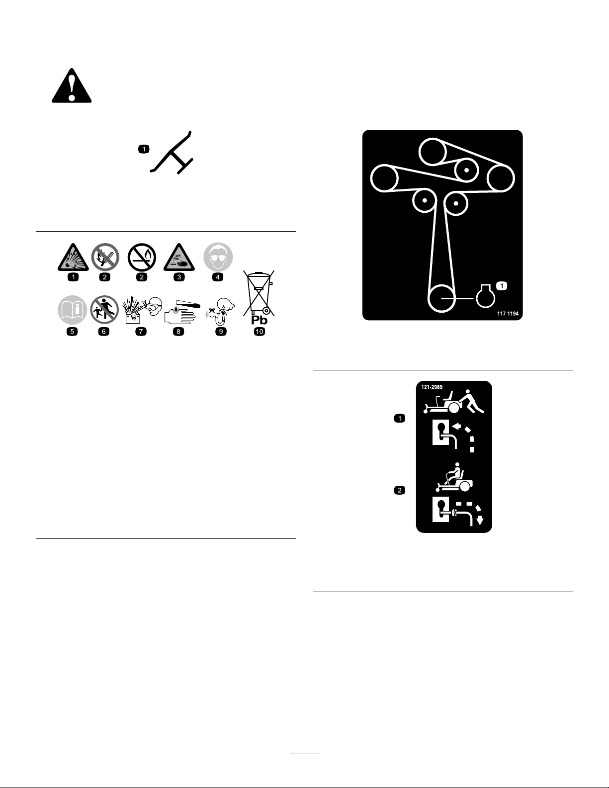
decal117-1 194
decalbatterysymbols
1.Engine
117-1194
1.Explosionhazard
2.Nore,opename,or
smoking
3.Causticliquid/chemical
burnhazard
4.Weareyeprotection.9.Flusheyesimmediately
5.ReadtheOperator's
Manual.
6.Keepbystandersasafe
7.Weareyeprotection;
8.Batteryacidcancause
10.Containslead;donot
distanceawayfromthe
battery.
explosivegasescan
causeblindnessandother
injuries.
blindnessorsevereburns.
withwaterandgetmedical
helpfast.
discard
1.Bypassleverpositionfor
pushingthemachine
decal121-2989
121-2989
2.Bypassleverpositionfor
operatingthemachine
6

decal131-1097
131-3948
131-1097
1.Oildrain
decal130-0654
130-0654
1.Transport—lock
2.Transport—unlock
1.Warning—thrownobject
hazard;keepthedeector
shieldinplace.
1.ReadtheOperator's
Manual.
2.Height-of-cutselection
3.Heightofcut
130-0731
2.Cuttinghazardofhandor
foot,mowerblade—keep
awayfrommovingparts.
130-0765
3.Removethekeyfromthe
keyswitchandreadthe
Operator'sManualbefore
performingmaintenance.
decal131-3948
decal130-0731
1.Slow
131-3948
3.Fast
2.Towing
decal132-0872
132-0872
1.Thrownobject
hazard—keepbystanders
awayfromthemachine.
decal130-0765
2.Thrownobjecthazard,
raisedbafe—donot
operatethemachinewith
anopendeck;usea
baggerorabafe.
3.Severinghazardofhand
orfoot—keepawayfrom
movingparts.
4.Entanglement
hazard—keepaway
frommovingparts;keep
allguardsandshieldsin
place.
7

136-4243
1.Fast4.Reverse
2.Slow
5.Parkingbrakedisengaged
3.Neutral6.Parkingbrakeengaged
136-4244
1.Fast3.Neutral
2.Slow
4.Reverse
decal136-4243
decal136-5596
136-5596
1.Checkthetirepressure
every25operatinghours.
2.Engineoil
3.Checkthetirepressure
every25operatinghours.
decal136-4244
1.ReadtheOperator'sManualbeforeaddingweighttothe
bucket.
4.Checkthetirepressure
every25operatinghours.
5.ReadtheOperator's
Manualbeforeperforming
maintenance.
decal136-9186
136-9186
decal136-4245
136-4245
ForMachineswithMyRide™
1.Slow
2.Transport
3.Fast
8
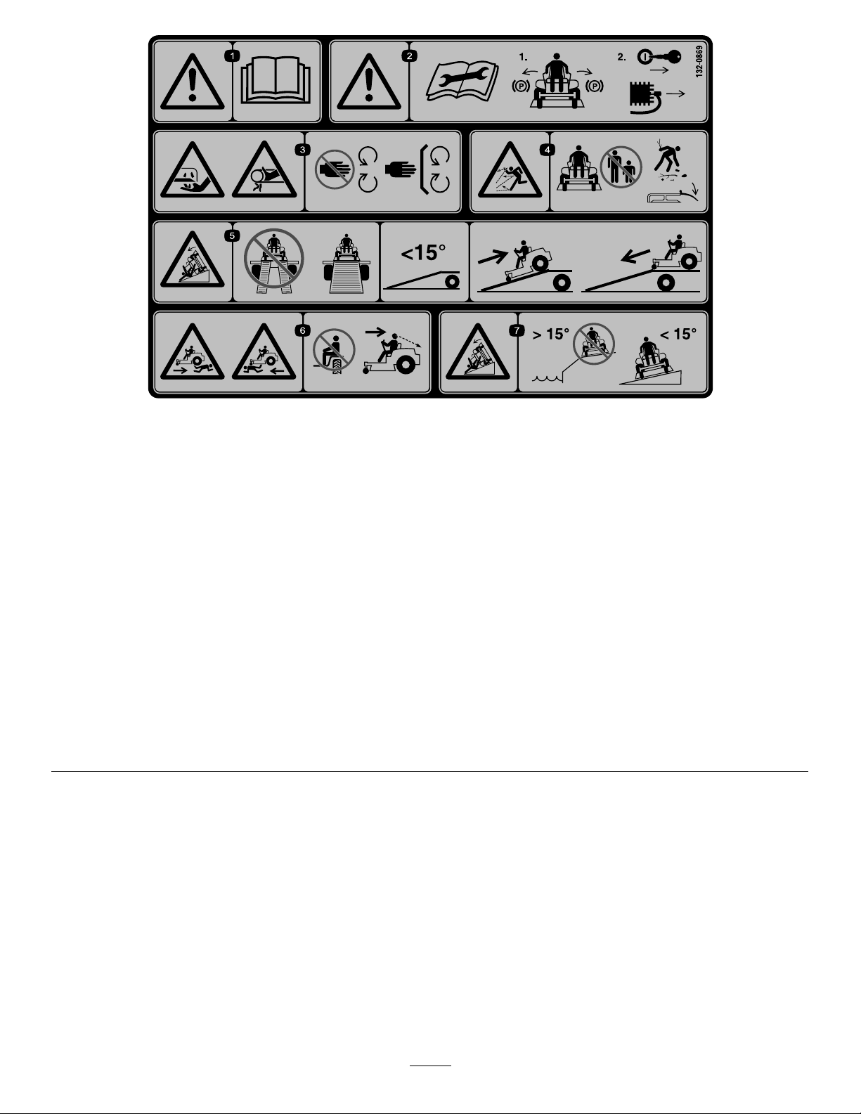
132-0869
Note:Thismachinecomplieswiththeindustrystandardstabilitytestinthestaticlateralandlongitudinaltestswiththemaximum
recommendedslopeindicatedonthedecal.ReviewtheinstructionsforoperatingthemachineonslopesintheOperator’sManualas
wellastheconditionsinwhichyouwouldoperatethemachinetodeterminewhetheryoucanoperatethemachineinthoseconditions
onthatdayandatthatsite.Changesintheterraincanresultinachangeinslopeoperationforthemachine.Ifpossible,keepthe
cuttingunitsloweredtothegroundwhileoperatingthemachineonslopes.Raisingthecuttingunitswhileoperatingonslopescan
causethemachinetobecomeunstable.
decal132-0869
1.Warning—readthe
Operator'sManual.
2.Warning—beforeservicing,
engagetheparkingbrake,
removethekeyandthe
sparkplugconnection.
3.Cuttinghazardofhand,
mowerblade;pinching
hazardofhand,belt—keep
handsandfeetawayfrom
movingparts;keepall
guardsandshieldsinplace.
4.Thrownobject
hazard—keepbystanders
awayfromthemachine;
removedebrisfromthe
areabeforemowing;keep
thedeectorshielddown.
5.Ramptipping
hazard—whenloading
ontoatrailer,donotuse
dualramps;useonlya
singlerampwideenough
forthemachineandthat
hasaninclinelessthan
15degrees;backupthe
ramp(inreverse)anddrive
forwardofftheramp.
6.Bodilyharmhazard—no
riders;lookbehindyou
whenmowinginreverse.
7.Tippinghazardon
slopes—donotuseon
slopesnearopenwater;do
notuseonslopesgreater
than15degrees.
9

133-9255
Note:Thismachinecomplieswiththeindustrystandardstabilitytestinthestaticlateralandlongitudinaltestswiththemaximum
recommendedslopeindicatedonthedecal.ReviewtheinstructionsforoperatingthemachineonslopesintheOperator’sManualas
wellastheconditionsinwhichyouwouldoperatethemachinetodeterminewhetheryoucanoperatethemachineinthoseconditions
onthatdayandatthatsite.Changesintheterraincanresultinachangeinslopeoperationforthemachine.Ifpossible,keepthe
cuttingunitsloweredtothegroundwhileoperatingthemachineonslopes.Raisingthecuttingunitswhileoperatingonslopescan
causethemachinetobecomeunstable.
decal133-9255
1.Warning—readtheOperator'sManual.
2.Ramphazard—donotusedualrampswhenloadingontoa
5.Tippinghazard—donotuseonslopesnearopenwater;do
6.Cuttingandpinchhazard—keepawayfrommovingparts;
trailer;use1rampwideenoughforthemachine;usearamp
withaslopelessthan15°;backuptherampwhenloadingthe
machineanddriveforwardofftherampwhenunloading.
3.Thrownobjecthazard—keepbystandersasafedistancefrom
7.Warning—beforeperformingmaintenance,readthe
themachine,pickupdebrisbeforeoperating,andkeepthe
deectorshielddown.
4.Bodilyharmhazard—donotcarrypassengers;lookbehind
youwhenmowinginreverse.
133-5198
1.Camlock2.Camunlock
notuseonslopesgreaterthan15°.
keepallguardsandshieldsinplace.
Operator'sManual;engagetheparkingbrake,removethe
key,anddisconnectthesparkplug.
decal133-5198
10

decal133-9263
133-9263
1.Fast
2.Slow5.PTOengage
3.Choke
4.PTOdisengage
11
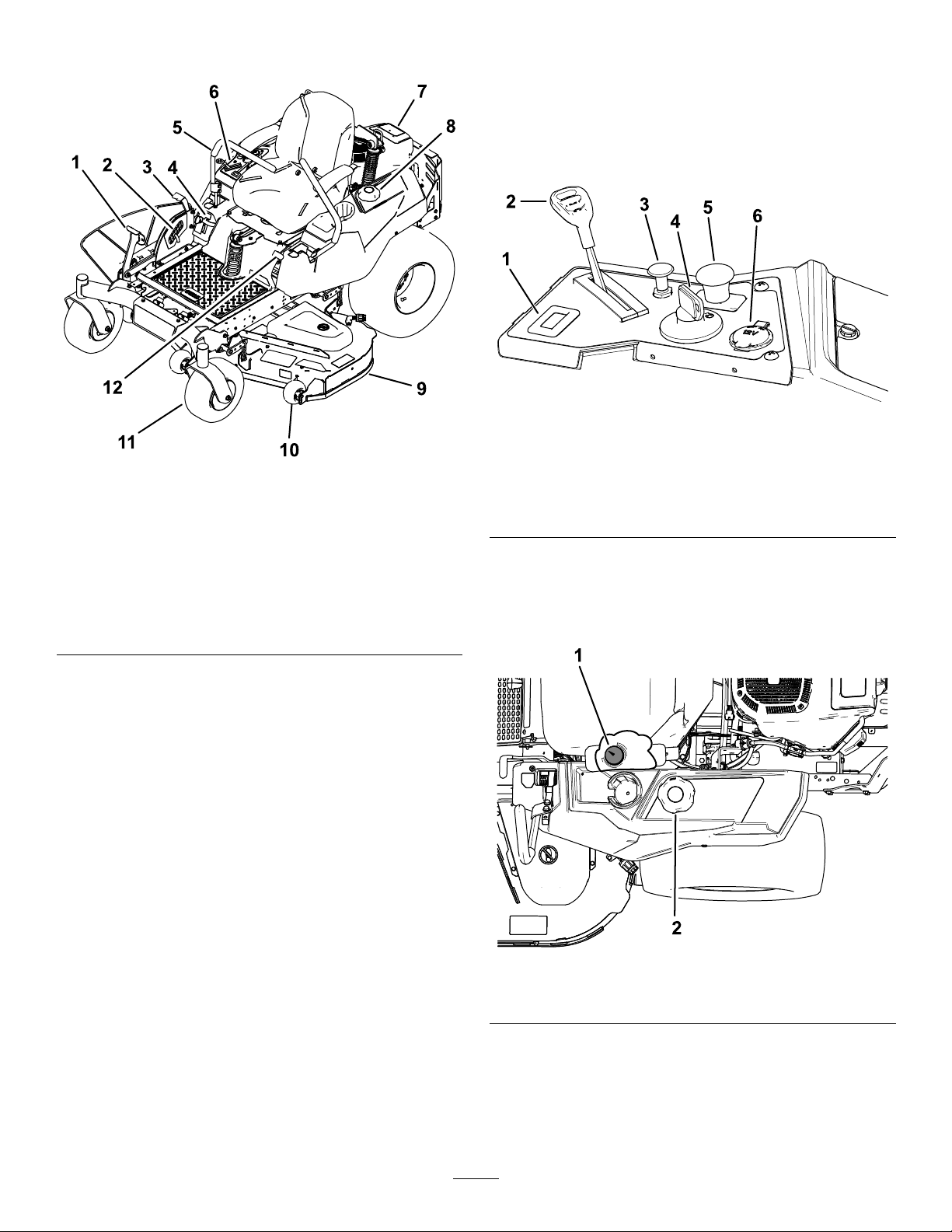
ProductOverview
Controls
BecomefamiliarwithallcontrolsinFigure6and
Figure7beforeyoustarttheengineandoperatethe
machine.
ControlPanel
g188738
Figure6
1.Deck-liftpedal
2.Height-of-cutpin
3.Height-of-cut
lever/transportlock
4.SmartSpeed™lever
5.Motion-controllever
6.Controls
Figure5
7.Engine
8.Fuelcap
9.Mowerdeck
10.Anti-scalproller
11.Casterwheel
12.Parking-brakelever
g195717
1.Hourmeter4.Keyswitch
2.Throttlecontrol5.Blade-controlswitch
3.Chokecontrol
(powertakeoff)
6.12Vpowerpoint
FuelGauge
Thefuelgaugedisplaystheamountoffuelinthetank
(Figure7).
Figure7
1.Fuelgauge2.Fuel-tankcap
ThrottleControl
Thethrottlecontrolstheenginespeed,andithasa
continuous-variablesettingfromtheSLOWtoFAST
position(Figure6).
12
g238298

ChokeControl
12VPowerPoint
Usethechokecontroltostartacoldengine.
HourMeter
Thehourmeterrecordsthenumberofhoursthe
enginehasoperated.Itoperateswhentheengine
isrunning.Usethesetimesforschedulingregular
maintenance(Figure6).
Motion-ControlLevers
Usethemotion-controlleverstodrivethemachine
forward,reverse,andturneitherdirection(Figure5).
Neutral-LockPosition
Movethemotion-controlleversoutwardfromthe
centertotheNEUTRAL-LOCKpositionwhenexiting
themachine(Figure32).Alwayspositionthe
motion-controlleversintotheNEUTRAL-LOCKposition
whenyoustopthemachineorleaveitunattended.
Parking-BrakeLever
Theparking-brakeleverislocatedontheleftsideof
theconsole(Figure5).Thebrakeleverengagesa
parkingbrakeonthedrivewheels.
Usethepowerpointtopower12Vaccessories
(Figure6).
Important:Whennotusingthe12Vpowerpoint,
inserttherubberplugtopreventdamagetothe
powerpoint.
KeySwitch
Thekeyswitch,usedtostartandshutofftheengine,
has3positions:OFF,RUN,andST ART.Referto
StartingtheEngine(page27).
Blade-ControlSwitch(Power
Takeoff)
Theblade-controlswitch,representedbya
power-takeoff(PTO)symbol,engagesand
disengagespowertothemowerblades(Figure6).
Height-of-CutLever
Theheight-of-cutleverworkswiththefootpedalto
lockthedeckinaspeciccuttingheight.Adjustthe
heightofcutonlywhenthemachineisnotmoving
(Figure5).
Toengagetheparkingbrake,pulluptheleveruntilit
latchesintothedetentslot.
Todisengagetheparkingbrake,pulltheleveroutof
thedetentslotandtowardyou,thenpushitdown.
FootPedalDeck-LiftSystem
Thefootpedaldeck-liftsystemallowsyoutolower
andraisethedeckfromtheseatedposition.You
canusethefootpedaltoliftthedeckbrieytoavoid
obstaclesorlockthedeckinthehighestheightofcut
ortransportposition(Figure5).
SmartSpeed™ControlSystem
Lever
TheSmartSpeed™Control-Systemlever,located
belowtheoperatingposition,givesyouachoiceto
drivethemachineat3speedranges—trim,tow,and
mow(Figure5).
Attachments/Accessories
AselectionofT oroapprovedattachmentsand
accessoriesisavailableforusewiththemachine
toenhanceandexpanditscapabilities.Contact
yourAuthorizedServiceDealerorauthorizedT oro
distributororgotowww.Toro.comforalistofall
approvedattachmentsandaccessories.
Toensureoptimumperformanceandcontinuedsafety
certicationofthemachine,useonlygenuineT oro
replacementpartsandaccessories.Replacement
partsandaccessoriesmadebyothermanufacturers
couldbedangerous,andsuchusecouldvoidthe
productwarranty.
13

Operation
Note:Determinetheleftandrightsidesofthe
machinefromthenormaloperatingposition.
Pre-Start
Fillfueltankonlevelground.SeeFuel
RecommendationsintheSpecicationssectionfor
additionalgasolineinformation.
DoNotaddoiltogasoline.
BeforeOperation
BeforeOperationSafety
•Evaluatetheterraintodeterminewhataccessories
andattachmentsareneededtoproperlyand
safelyperformthejob.Onlyuseaccessoriesand
attachmentsapprovedbyToro.
•Inspecttheareawheretheequipmentistobe
usedandremoveallrocks,toys,sticks,wires,
bones,andotherforeignobjects.Thesecan
bethrownorinterferewiththeoperationofthe
machineandmaycausepersonalinjurytothe
operatororbystanders.
•Wearappropriatepersonalprotectiveequipment
suchassafetyglasses,substantialslip-resistant
footwear,andhearingprotection.Tiebacklong
hairandavoidlooseclothingandloosejewelry
whichmaygettangledinmovingparts.
CAUTION
Thismachineproducessoundlevelsin
excessof85dBAattheoperator’searand
cancausehearinglossthroughextended
periodsofexposure.
DoNotoverllfueltank.Fillthefueltanktothebottom
ofthellerneck.Theemptyspaceinthetankallows
gasolinetoexpand.Overllingmayresultinfuel
leakageordamagetotheengineoremissionsystem.
Makesureyouunderstandthecontrols,theirlocations,
theirfunctions,andtheirsafetyrequirements.
RefertotheMaintenancesectionandperformallthe
necessaryinspectionandmaintenancesteps.
Wearhearingprotectionwhenoperating
thismachine.
•Checkthattheoperatorpresencecontrols,
safetyswitches,andshieldsareattachedand
functioningproperly.DoNotoperateunlessthey
arefunctioningproperly.
•DoNotoperatethemowerwhenpeople,especially
children,orpetsareinthearea.Stopthemachine
andattachment(s)ifanyoneentersthearea.
•DoNotoperatethemachinewithouttheentire
grasscollectionsystem,dischargedeector,
orothersafetydevicesinplaceandinproper
workingcondition.Grasscatchercomponents
aresubjecttowear,damageanddeterioration,
whichcouldexposemovingpartsorallowobjects
tobethrown.Frequentlycheckforwornor
deterioratingcomponentsandreplacethemwith
themanufacturer’srecommendedpartswhen
necessary.
14

FuelSafety
DANGER
Useextremecarewhenhandlingfuel.
DANGER
Incertainconditionsgasolineisextremely
ammableandvaporsareexplosive.
Areorexplosionfromgasolinecanburn
you,others,andcausepropertydamage.
•Fillthefueltankoutdoorsonlevelground,
inanopenarea,whentheengineiscold.
Wipeupanygasolinethatspills.
•Neverrellthefueltankordrainthe
machineindoorsorinsideanenclosed
trailer.
•DoNotllthefueltankcompletelyfull.
Fillthefueltanktothebottomoftheller
neck.Theemptyspaceinthetankallows
gasolinetoexpand.Overllingmayresult
infuelleakageordamagetotheengineor
emissionsystem.
•Neversmokewhenhandlinggasoline,and
stayawayfromanopenameorwhere
gasolinefumesmaybeignitedbyspark.
•Storegasolineinanapprovedcontainer
andkeepitoutofthereachofchildren.
Incertainconditionsduringfueling,static
electricitycanbereleasedcausingaspark
whichcanignitegasolinevapors.Areor
explosionfromgasolinecanburnyouand
othersandcausepropertydamage.
•Alwaysplacegasolinecontainersonthe
groundawayfromyourvehiclebefore
lling.
•DoNotllgasolinecontainersinsidea
vehicleoronatruckortrailerbedbecause
interiorcarpetsorplastictruckbedliners
mayinsulatethecontainerandslowthe
lossofanystaticcharge.
•Whenpractical,removegas-powered
equipmentfromthetruckortrailerand
refueltheequipmentwithitswheelsonthe
ground.
•Ifthisisnotpossible,thenrefuelsuch
equipmentonatruckortrailerfroma
portablecontainer,ratherthanfroma
gasolinedispensernozzle.
•Ifagasolinedispensernozzlemustbe
used,keepthenozzleincontactwiththe
rimofthefueltankorcontaineropeningat
alltimesuntilfuelingiscomplete.DoNot
useanozzlelockopendevice.
•Addfuelbeforestartingtheengine.Never
removethecapofthefueltankoraddfuel
whenengineisrunningorwhentheengine
ishot.
•Iffuelisspilled,DoNotattempttostart
theengine.Moveawayfromtheareaof
thespillandavoidcreatinganysourceof
ignitionuntilfuelvaporshavedissipated.
•DoNotoperatewithoutentireexhaust
systeminplaceandinproperworking
condition.
WARNING
Gasolineisharmfulorfatalifswallowed.
Long-termexposuretovaporshascaused
cancerinlaboratoryanimals.Failuretouse
cautionmaycauseseriousinjuryorillness.
•Avoidprolongedbreathingofvapors.
•Keepfaceawayfromnozzleandgas
tank/containeropening.
•Keepawayfromeyesandskin.
•Neversiphonbymouth.
Tohelppreventres:
•Keepengineandengineareafreefrom
accumulationofgrass,leaves,excessivegrease
oroil,andotherdebriswhichcanaccumulatein
theseareas.
•Cleanupoilandfuelspillsandremovefuelsoaked
debris.
•Allowthemachinetocoolbeforestoringthe
machineinanyenclosure.DoNotstorenear
ameoranyenclosedareawhereopenpilotlights
orheatappliancesarepresent.
15
AddingFuel
RecommendedFuel
•Forbestresults,useonlyclean,fresh(lessthan
30daysold),unleadedgasolinewithanoctane
ratingof87orhigher((R+M)/2ratingmethod).
•Ethanol:Gasolinewithupto10%ethanol
(gasohol)or15%MTBE(methyltertiarybutyl
ether)byvolumeisacceptable.Ethanoland
MTBEarenotthesame.Gasolinewith15%
ethanol(E15)byvolumeisnotapprovedforuse.
Neverusegasolinethatcontainsmorethan
10%ethanolbyvolume,suchasE15(contains
15%ethanol),E20(contains20%ethanol),orE85
(containsupto85%ethanol).Usingunapproved
gasolinemaycauseperformanceproblemsand/or
enginedamagewhichmaynotbecoveredunder
warranty.
•Donotusegasolinecontainingmethanol.
•Donotstorefueleitherinthefueltankorfuel
containersoverthewinterunlessyouuseafuel
stabilizer.
•Donotaddoiltogasoline.
g197123
Figure8
UsingStabilizer/Conditioner
Usefuelstabilizer/conditionerinthemachineatall
timestokeepthefuelfreshlongerwhenusedas
directedbythefuel-stabilizermanufacturer.
Important:Donotusefueladditivescontaining
methanolorethanol.
Addtheamountoffuelstabilizer/conditionertofresh
fuelasdirectedbythefuel-stabilizermanufacturer.
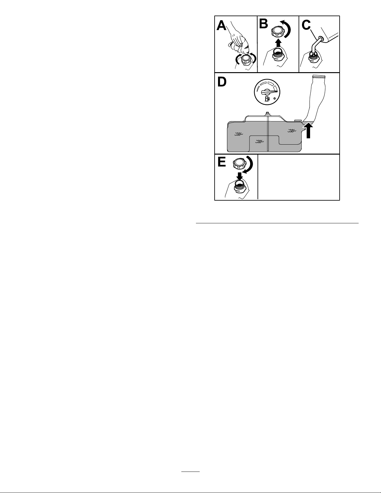
FillingtheFuelTank
1.Parkthemachineonalevelsurface.
2.Engagetheparkingbrake.
3.Shutofftheengineandremovethekey.
4.Cleanaroundthefuel-tankcap.
5.Fillthefueltankuntilthefuelgaugereadsatthe
fullmark(Figure8).
Note:Donotllthefueltankcompletelyfull.
Theemptyspaceinthetankallowsthefuelto
expand.
PerformingDaily Maintenance
Beforestartingthemachineeachday ,performthe
EachUse/DailyprocedureslistedinMaintenance
(page37).
BreakinginaNewMachine
Newenginestaketimetodevelopfullpower.Mower
decksanddrivesystemshavehigherfrictionwhen
new,placingadditionalloadontheengine.Allow
40to50hoursofbreak-intimefornewmachinesto
developfullpowerandbestperformance.
16
UsingtheSafety-Interlock System
WARNING
Ifthesafety-interlockswitchesare
disconnectedordamaged,themachinecould
operateunexpectedly,causingpersonal
injury.
•Donottamperwiththeinterlockswitches.
•Checktheoperationoftheinterlock
switchesdailyandreplaceanydamaged
switchesbeforeoperatingthemachine.
Understandingthe Safety-InterlockSystem
Thesafety-interlocksystemisdesignedtopreventthe
enginefromstartingunless:
•Theblade-controlswitch(PTO)isdisengaged.
andriseslightlyfromtheseat;theengineshould
shutoff.
4.Sitontheseat,engagetheparkingbrake,
movetheblade-controlswitch(PTO)totheOFF
position,andmovethemotion-controllevers
toNEUTRAL-LOCKposition.Starttheengine.
Whiletheengineisrunning,centereither
motion-controlleverandmoveitforwardor
reverse;theengineshouldshutoff.Repeatfor
othermotion-controllever.
5.Sitontheseat,disengagetheparkingbrake,
movetheblade-controlswitch(PTO)totheOFF
position,andmovethemotion-controlleversto
NEUTRAL-LOCKposition.Trystartingtheengine;
theengineshouldnotcrank.
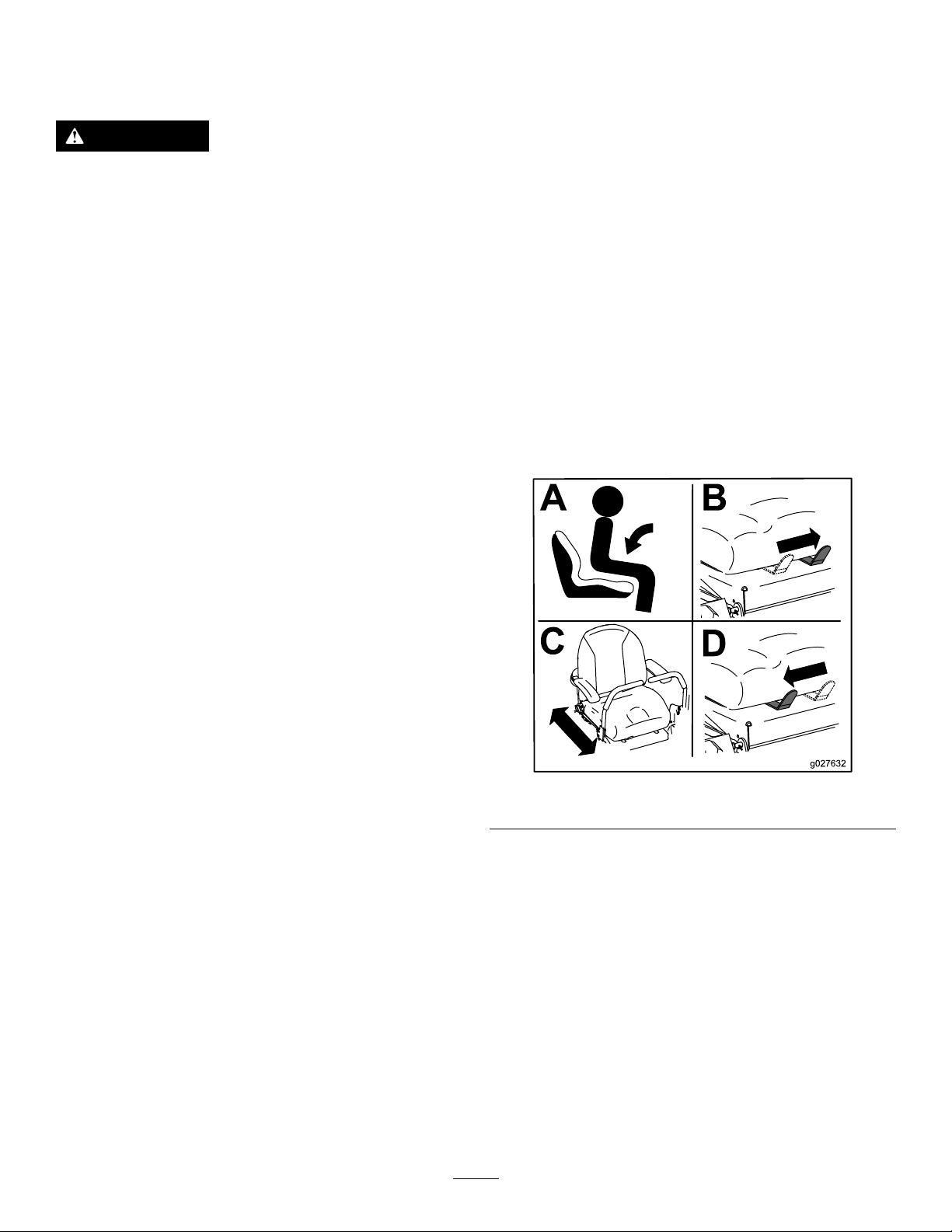
PositioningtheSeat
Theseatcanmoveforwardandbackward.Position
theseatwhereyouhavethebestcontrolofthe
machineandaremostcomfortable(Figure9).
•Themotion-controlleversareintheNEUTRAL-LOCK
position.
•Theparkingbrakeisengaged.
Thesafety-interlocksystemalsoisdesignedtoshut
offtheenginewheneverthecontrolleversareoutof
theNEUTRAL-LOCKpositionandyourisefromtheseat.
TestingtheSafety-Interlock System
ServiceInterval:Beforeeachuseordaily
Testthesafety-interlocksystembeforeyouusethe
machineeachtime.Ifthesafetysystemdoesnot
operateasdescribedbelow,haveanAuthorized
ServiceDealerrepairthesafetysystemimmediately .
1.Sitontheseat,engagetheparkingbrake,and
movetheblade-controlswitch(PTO)totheON
position.Trystartingtheengine;theengine
shouldnotcrank.
2.Sitontheseat,engagetheparkingbrake,and
movetheblade-controlswitch(PTO)totheOFF
position.Moveeithermotion-controllever(out
oftheNEUTRAL-LOCKposition).Trystartingthe
engine;theengineshouldnotcrank.Repeatfor
othercontrollever.
g027632
Figure9
3.Sitontheseat,engagetheparkingbrake,
movetheblade-controlswitch(PTO)totheOFF
position,andmovethemotion-controlleversto
theNEUTRAL-LOCKposition.Starttheengine.
Whiletheengineisrunning,releasetheparking
brake,engagetheblade-controlswitch(PTO),
17
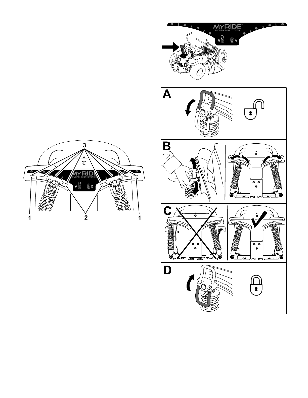
AdjustingtheMyRide™ SuspensionSystem
TheMyRide™suspensionsystemadjuststoprovide
asmoothandcomfortableride.Youcanadjustthe
rear2-shockassembliestoquicklyandeasilychange
thesuspensionsystem.Positionthesuspension
systemwhereyouaremostcomfortable.
Adjusttherear-shockassemblies(Figure11).
AdjustingtheRear-Shock Assemblies
Theslotsfortherear-shockassemblieshave
detentpositionsforreference.Youcanpositionthe
rear-shockassembliesanywhereintheslot,notjust
inthedetentpositions.
Thefollowinggraphicshowsthepositionforasoftor
rmrideandthedifferentdetentpositions(Figure10).
Figure10
g195746
g195744
1.Firmestposition3.Detentsintheslots
2.Softestposition
Note:Ensurethattheleftandrightrear-shock
assembliesarealwaysadjustedtothesamepositions.
g195745
Figure11
18
Adjustingthe
WARNING
Motion-ControlLevers
AdjustingtheHeight
Youcanadjustthemotion-controllevershigheror
lowerformaximumcomfort(Figure12).
Figure12
AdjustingtheTilt
Youcanadjustthemotion-controlleversforwardor
rearwardforyourcomfort.
Openholesinthemachineexposeyouand
otherstothrowndebristhatcancausesevere
injury.
•Neveroperatethemachinewithout
hardwaremountedinallholesinthe
machinehousing.
•Installthehardwareinthemountingholes
whenyouremovethemulchingbafe.
Machineswith122cm(48-inch) MowerDecks
1.Parkthemachineonalevelsurface,disengage
theblade-controlswitch,andengagetheparking
brake.
2.Shutofftheengine,removethekey,andwait
forallmovingpartstostopbeforeleavingthe
g027252
operatingposition.
3.Removethemowerdeck;refertoRemovingthe
MowerDeck(page54).
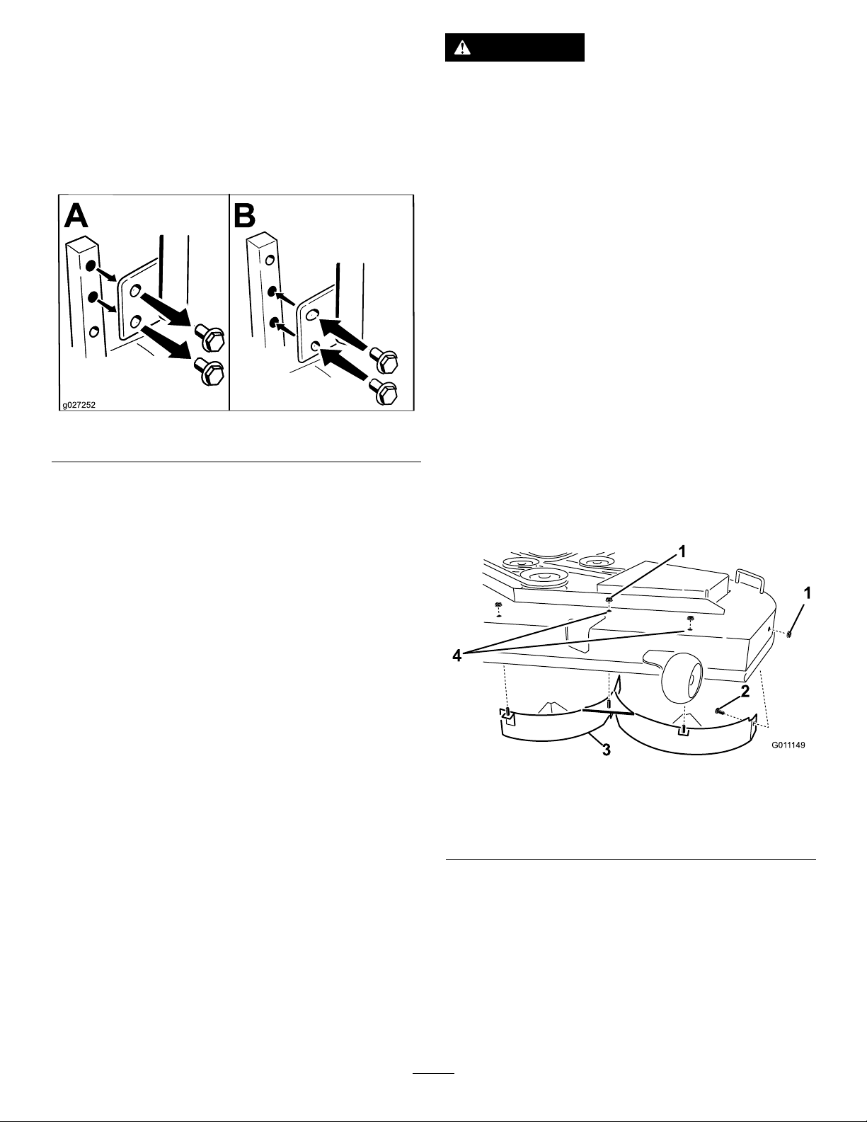
4.Removethe2locknuts(5/16inch)securedto
theweldedpostsoftheleftbafeonthetopof
themowerdeckatthecenterandleftofcenter
positions(Figure13).
1.Loosentheupperboltholdingthecontrollever
tothecontrol-armshaft.
2.Loosenthelowerboltjustenoughtopivotthe
controlleverforwardorrearward(Figure12).
3.Tightenbothboltstosecurethecontrolleverin
thenewposition.
4.Repeattheadjustmentfortheothercontrollever.
ConvertingtoSide Discharge
Themowerdeckandmowerbladesshippedwiththe
machineweredesignedforoptimummulchingand
side-dischargeperformance.
Installthefastenersintothesameholesinthedeck
fromwheretheywereoriginallyremoved.This
ensuresthatnoholesareleftopenwhenoperating
themowerdeck.
Figure13
1.Locknut(5/16inch)3.Leftbafe
2.Carriagebolt(5/16x3/4
inch)
5.Removethecarriageboltandlocknutonthe
sidewallofthemowerdecksecuringtheleft
bafetothedeck.
6.Removetheleftbafefromthemowerdeckas
showninFigure13.
7.Removethe2carriagebolts(5/16x3/4
inch)and2locknuts(5/16inch)securingthe
assembledrightbafeandbafeguardtothe
mowerdeck(Figure14).
4.Installthefastenershere.
g011 149
19
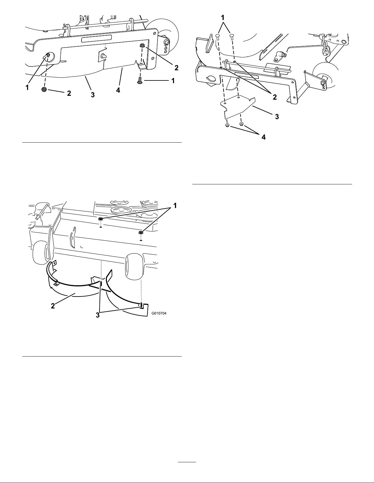
Figure14
g191136
1.Carriagebolt(5/16x3/4
inch)
2.Locknut(5/16inch)4.Bafeguard
3.Rightbafe
8.Removethe2locknuts(5/16inch)tosecuring
theweldedpostsoftherightbafetothetopof
themowerdeckatthecenterandrightofcenter
positions(Figure15).
Note:Removetherightbafefromthemower
deck.
Figure16
1.Carriagebolts(existing)3.Cutoffbafe(loose)
2.Rearholesinthe
dischargeplate
4.Locknuts(existing)
10.Installthebafeatthesidedischargeopening
onthemowerdeck.
11.Usethefastenersremovedtosecurethecutoff
bafetothedeck.
12.Installthemowerdeck;refertoInstallingthe
MowerDeck(page55).
Machineswith137cm(54-inch) MowerDecks
1.Parkthemachineonalevelsurface,disengage
theblade-controlswitch,andengagetheparking
brake.
g190734
Figure15
1.Locknut(5/16inch)3.Weldedposts(rightbafe)
2.Rightbafe
9.Locatethecutoffbafeintheloosepartsbag
andremovethefastenersattherearholesof
thedischargeplate(Figure16).
2.Shutofftheengine,removethekey ,andwait
forallmovingpartstostopbeforeleavingthe
g010704
operatingposition.
3.Removethemowerdeck;refertoRemovingthe
MowerDeck(page54).
4.Removethe3locknuts(5/16inch)securedto
theweldedpostsoftheleftbafeonthetopof
themowerdeckatthecenter,leftofcenter,and
leftpositions(Figure17).
20
 Loading...