

Page 1
FormNo.3410-234RevB
TimeCutter
ModelNo.74864—SerialNo.400000000andUp
ModelNo.74865—SerialNo.400000000andUp
ModelNo.74866—SerialNo.400000000andUp
ModelNo.74867—SerialNo.400000000andUp
ModelNo.75201—SerialNo.400000000andUp
ModelNo.75202—SerialNo.400000000andUp
ModelNo.75203—SerialNo.400000000andUp
ModelNo.75210—SerialNo.400000000andUp
ModelNo.75211—SerialNo.400000000andUp
ModelNo.75212—SerialNo.400000000andUp
ModelNo.75213—SerialNo.400000000andUp
®
HDRidingMower
SetupInstructions
Setup
LooseParts
Usethechartbelowtoverifythatallpartshavebeenshipped.
ProcedureDescription
1
2
3
4
5
Note:Determinetheleftandrightsidesofthemachinefromthenormaloperatingposition.
Nopartsrequired
Rearhitch1
Bolt(5/16x1inch)
Locknut(5/16inch)
Nopartsrequired
Nopartsrequired
Ignitionkey1
Hosecoupling(non-CEmachinesonly)
Operator'sManual
Engineowner’smanual(non-T oro
enginesonly)
Operatortrainingmaterial
Qty.
Use
–
2
2
–
–
1
1
1
1
Connectthebattery.
Installtherearhitch.
Setupthemotion-controllevers(CE
machinesonly).
Checkthemoweradjustment.
Completethesetup.
©2017—TheT oro®Company
8111LyndaleAvenueSouth
Bloomington,MN55420
Registeratwww.T oro.com.
OriginalInstructions(EN)
PrintedintheUSA
AllRightsReserved
*3410-234*B
Page 2
1
ConnectingtheBattery
NoPartsRequired
Procedure
WARNING
CALIFORNIA
Proposition65Warning
Batteryposts,terminals,andrelated
accessoriescontainleadandleadcompounds,
chemicalsknowntotheStateofCalifornia
tocausecancerandreproductiveharm.
Washhandsafterhandling .
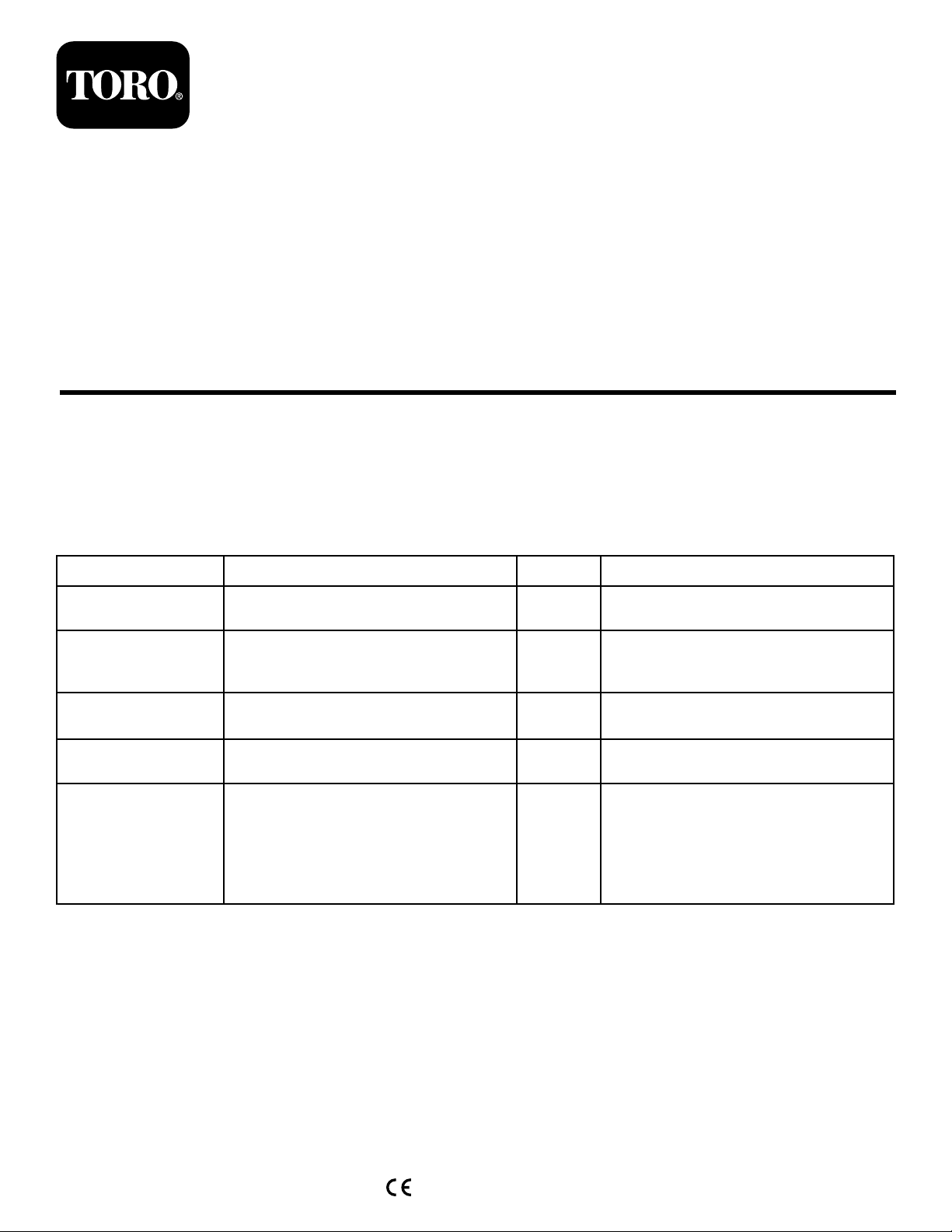
1.Loosenthe2fastenersonthebatterycover
counterclockwise1/4turnandremovethebattery
cover(Figure1).
Figure1
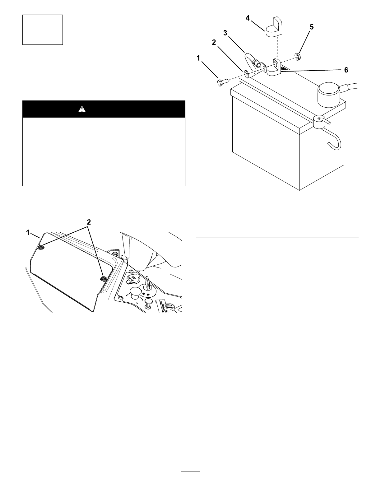
2.Removetheplasticcapfromthenegativebatterypost.
3.Removethefastenersonthenegativebatterycable,
andusethemtosecurethenegativebatterycableto
thenegativebatterypost(Figure2).
g197768
Figure2
1.Hexbolt4.Negativebatterypostcap
2.Washer5.Nut
3.Negativebatterycable6.Negativebatterypost
g190587
2
Page 3

2
3
InstallingtheRearHitch
Partsneededforthisprocedure:
1Rearhitch
2
Bolt(5/16x1inch)
2
Locknut(5/16inch)
Procedure
InstallthebrackettotheframeasshowninFigure3and
Figure4.
SettingUptheMotion-Control
Levers
CEMachinesOnly
NoPartsRequired
Procedure
1.Locatethemotion-controlleversattached,butfolded
downonthemachine.
2.Removetheupperbolt(3/8x1inch)andwasher;
loosenthelowerbolt(3/8x1inch).
3.Raisethemotioncontrolleverstotheuprightposition.
4.Aligntheholesinthemotion-controlleverwiththe
holesinthecontrol-armshaft,andinstallthebolt
andwasherremovedpreviously.Repeatthisforboth
controlslevers.
Note:Handtightenallfasteners.
5.Movethemotion-controlleverstotheparkposition,
raisetheseat,andmovethecontrolleversbacktothe
centerposition(neutral).
Figure3
Beforeassembly
1.Bolt3.Locknut
2.Bracket
Figure4
Afterassembly
6.Verifythatthemotion-controlleversareproperly
g191160
aligned.
Note:Adjustasnecessary.Tightenallfasteners.
4
CheckingtheMower
Adjustment
NoPartsRequired
Procedure
g191159
Adjusttheside-to-sidelevelandthefront-to-rearbladeslope.
UsetherelevantproceduresintheOperator'sManualtoverify
thatthedeckislevel,andmakeanyadjustmentsasnecessary.
RefertotheOperator'sManualformoreinformation.
3
Page 4

5
CompletingtheSetup
Partsneededforthisprocedure:
1Ignitionkey
1
Hosecoupling(non-CEmachinesonly)
1
Operator'sManual
1
Engineowner’smanual(non-T oroenginesonly)
1
Operatortrainingmaterial
CheckingtheTirePressure
Checkthefrontandreartiresforproperination;referto
CheckingtheTirePressureintheOperator’ sManualforthe
recommendedinationpressure.
CheckingtheSide-DischargeChute
Removethepackingrestraintholdingtheside-dischargechute
upandlowerthechuteintoplace.
CheckingtheEngine-OilLevel
Beforeyoustarttheengineandusethemachine,checkthe
oillevelintheenginecrankcase;refertoCheckingtheOil
LevelintheOperator'sManual.
CheckingtheAirCleaner
Ensurethattheaircleanerisproperlyinstalledintheengine
air-cleanerbox.
OrganizingtheMaterial
Keepallthefollowingitemswiththemachine:
•Ignitionkey
•Hosecoupling(non-CEmachinesonly)
•Operator'sManual
•Engineowners’smanual(non-Toroenginesonly)
•Viewtheoperatortrainingmaterialbeforeoperatingthe
machine.
4
 Loading...