

Page 1
FormNo.3400-849RevC
TITAN
®
ZX4800,ZX5400,or
ZX6000Zero-Turn-RadiusRiding
Mower
ModelNo.74861—SerialNo.316000001andUp
ModelNo.74862—SerialNo.316000001andUp
ModelNo.74863—SerialNo.316000001andUp
Registeratwww.T oro.com.
OriginalInstructions(EN)
*3400-849*C
Page 2
ItisaviolationofCaliforniaPublicResourceCode
Section4442or4443touseoroperatetheengineon
anyforest-covered,brush-covered,orgrass-covered
landunlesstheengineisequippedwithaspark
arrester,asdenedinSection4442,maintainedin
effectiveworkingorderortheengineisconstructed,
equipped,andmaintainedforthepreventionofre.
ThissparkignitionsystemcomplieswithCanadian
ICES-002
TheenclosedEngineOwner'sManualis
suppliedforinformationregardingtheUS
EnvironmentalProtectionAgency(EPA)and
theCaliforniaEmissionControlRegulationof
emissionsystems,maintenance,andwarranty.
Replacementsmaybeorderedthroughtheengine
manufacturer.
Introduction
Thismachineisaride-on,rotary-bladelawnmower
intendedtobeusedbyhomeownersinresidential
applications.Itisprimarilydesignedforcuttinggrass
onwell-maintainedlawns.Itisnotdesignedforcutting
brush,mowinggrassandothergrowthalongside
highways,orforagriculturaluses.
Readthisinformationcarefullytolearnhowtooperate
andmaintainyourproductproperlyandtoavoid
injuryandproductdamage.Youareresponsiblefor
operatingtheproductproperlyandsafely .
YoumaycontactT orodirectlyatwww.T oro.com
forproductsafetyandoperationtrainingmaterials,
accessoryinformation,helpndingadealer,orto
registeryourproduct.
WARNING
CALIFORNIA
Proposition65Warning
Theengineexhaustfromthisproduct
containschemicalsknowntotheStateof
Californiatocausecancer,birthdefects,
orotherreproductiveharm.
Wheneveryouneedservice,genuineToroparts,or
additionalinformation,contactanAuthorizedService
DealerorToroCustomerServiceandhavethemodel
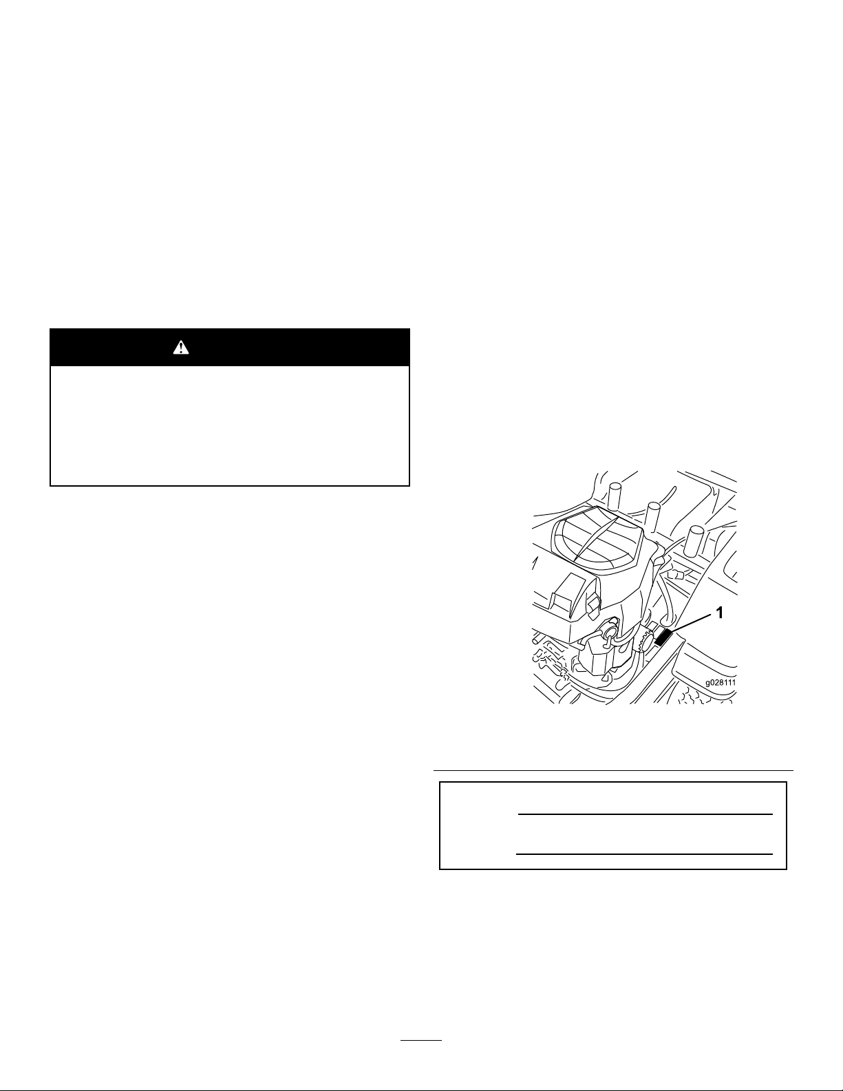
andserialnumbersofyourproductready.Figure1
identiesthelocationofthemodelandserialnumbers
ontheproduct.Writethenumbersinthespace
provided.
g02811 1
Figure1
1.Modelandserial-numberlocation
©2018—TheToro®Company
8111LyndaleAvenueSouth
Bloomington,MN55420
ModelNo.
SerialNo.
Contactusatwww.Toro.com.
2
PrintedintheUSA
AllRightsReserved
Page 3

Thismanualidentiespotentialhazardsandhas
safetymessagesidentiedbythesafety-alertsymbol
(Figure2),whichsignalsahazardthatmaycause
seriousinjuryordeathifyoudonotfollowthe
recommendedprecautions.
Figure2
1.Safety-alertsymbol
Thismanualuses2wordstohighlightinformation.
Importantcallsattentiontospecialmechanical
informationandNoteemphasizesgeneralinformation
worthyofspecialattention.
WARNING
Removingstandardoriginalequipmentparts
andaccessoriesmayalterthewarranty,
traction,andsafetyofthemachine.Failureto
useoriginalT oropartscouldcauseserious
injuryordeath.Makingunauthorizedchanges
totheengine,fuelorventingsystem,may
violateEPAandCARBregulations.
Replaceallpartsincluding,butnotlimited
to,tires,belts,blades,andfuelsystem
componentswithoriginalToroparts.
Formodelswithstatedenginehorsepower,thegross
horsepoweroftheenginewaslaboratorytestedby
theenginemanufacturerinaccordancewithSAE
J1995andratedtoJ2723.
Donottamperwiththeenginecontrolsoralterthe
governorspeed;doingsomaycreateanunsafe
conditionresultinginpersonalinjury.
Contents
Safety.......................................................................4
SafeOperatingPractices....................................4
ToroRidingMowerSafety...................................6
SlopeIndicator...................................................7
SafetyandInstructionalDecals..........................8
g000502
ProductOverview...................................................13
Controls...........................................................14
Operation................................................................15
AddingFuel......................................................15
ThinkSafetyFirst..............................................17
UsingtheRollover-ProtectionSystem
(ROPS).........................................................17
UnderstandingtheSafety-Interlock
System..........................................................18
TestingtheSafety-InterlockSystem..................18
CheckingtheEngine-OilLevel..........................18
BreakinginaNewMachine..............................18
OperatingtheParkingBrake.............................18
OperatingtheThrottle.......................................19
OperatingtheChoke.........................................19
OperatingtheIgnitionSwitch............................19
StartingandStoppingtheEngine......................19
OperatingtheBlade-ControlSwitch
(PTO)............................................................20
DrivingtheMachine..........................................21
StoppingtheMachine.......................................22
AdjustingtheHeightofCut...............................22
AdjustingtheAnti-ScalpRollers........................23
PositioningtheSeat..........................................24
AdjustingtheMotion-ControlLevers.................24
PushingtheMachinebyHand..........................24
UsingtheSideDischarge.................................25
TransportingtheMachine.................................26
LoadingtheMachine........................................26
OperatingTips.................................................28
Maintenance...........................................................29
RecommendedMaintenanceSchedule(s)...........29
Pre-MaintenanceProcedures..............................30
Service-IntervalChart.......................................30
RaisingtheSeat...............................................30
Lubrication..........................................................31
GreasingtheBearings......................................31
EngineMaintenance...........................................31
ServicingtheAirCleaner..................................31
ServicingtheEngineOil....................................32
ServicingtheSparkPlug...................................34
CleaningtheBlowerHousing............................35
FuelSystemMaintenance...................................36
ReplacingtheFuelFilter...................................37
ElectricalSystemMaintenance...........................37
ServicingtheBattery.........................................37
ServicingtheFuses..........................................38
DriveSystemMaintenance..................................39
CheckingtheTirePressure...............................39
HydraulicSystemMaintenance...........................40
CheckingtheHydraulic-FluidLevel...................40
3
Page 4

ChangingtheHydraulicFilterand
Fluid..............................................................40
MowerDeckMaintenance....................................42
ServicingtheCuttingBlades.............................42
LevelingtheMowerDeck..................................44
InspectingtheBelts..........................................46
ReplacingtheMowerBelt.................................46
RemovingtheMower........................................47
InstallingtheMowerDeck.................................48
ReplacingtheGrassDeector..........................48
Cleaning..............................................................49
WashingtheUndersideoftheMower................49
DisposingofWaste...........................................50
Storage...................................................................51
CleaningandStorage.......................................51
Troubleshooting......................................................52
Schematics.............................................................54
Safety
Improperlyusingormaintainingthemachinecan
resultininjury.Toreducethepotentialforinjury,
complywiththesesafetyinstructionsandalways
payattentiontothesafetyalertsymbol,which
meansCaution,Warning,orDanger—personal
safetyinstruction.Failuretocomplywiththe
instructionmayresultinpersonalinjuryordeath.
Thisproductiscapableofamputatinghandsand
feetandthrowingobjects.Alwaysfollowallsafety
instructionstoavoidseriousinjuryordeath.
Thisproductisdesignedforcuttingandrecycling
grassor,whenequippedwithagrassbagger,for
catchingcutgrass.Anyuseforpurposesotherthan
thesecouldprovedangeroustouserandbystanders.
SafeOperatingPractices
ThefollowinginstructionsareadaptedfromANSI
standardB71.4-2012.
Training
•ReadtheOperator'sManualandothertraining
material.Iftheoperator(s)ormechanic(s)cannot
readEnglishitistheowner'sresponsibilityto
explainthismaterialtothem.
•Becomefamiliarwiththesafeoperationofthe
equipment,operatorcontrols,andsafetysigns.
•Alloperatorsandmechanicsshouldbetrained.
Theownerisresponsiblefortrainingtheusers.
•Neverletchildrenoruntrainedpeopleoperateor
servicetheequipment.Localregulationsmay
restricttheageoftheoperator.
•Theowner/usercanpreventandisresponsible
foraccidentsorinjuriesoccurringtopeopleor
damagetoproperty.
Preparation
•Evaluatetheterraintodeterminewhataccessories
andattachmentsareneededtoproperlyand
safelyperformthejob.Useonlyaccessoriesand
attachmentsapprovedbythemanufacturer.
•Wearappropriateclothingincludingsubstantial
slip-resistantfootwear,ahardhat,eyeprotection,
andhearingprotection.Tiebacklonghair.Donot
wearjewelry.
•Inspecttheareawheretheequipmentistobe
usedandremoveallobjectssuchasrocks,toys
andwirewhichcanbethrownbythemachine.
•Checkthatoperator-presencecontrols,safety
switchesandshieldsareattachedandfunctioning
4
Page 5

properly.Donotoperatethemachineunlessthey
arefunctioningproperly.
Operation
•Lightningcancausesevereinjuryordeath.If
lightningisseenorthunderisheardinthearea,do
notoperatethemachine;seekshelter.
•Neverrunanengineinanenclosedarea.
•Onlyoperateingoodlight,keepingawayfrom
holesandhiddenhazards.
•EnsurethatalldrivesareinNEUTRALandthatthe
parkingbrakeisengagedbeforestartingengine.
Starttheengineonlyfromtheoperator'sposition.
•Slowdownanduseextracareonhillsides.Be
suretotravelsidetosideonhillsides.Turf
conditionscanaffectthemachine'sstability .Use
cautionwhileoperatingneardrop-offs.
•Slowdownandusecautionwhenmakingturns
andwhenchangingdirectionsonslopes.
•Neverraisethedeckwiththebladesrunning.
•NeveroperatewiththePTOshield,orotherguards
notsecurelyinplace.Ensurethatallinterlocks
areattached,adjustedproperly,andfunctioning
properly.
•Neveroperatewiththedischargedeectorraised,
removedoraltered,unlessusingagrasscatcher.
•Donotchangetheenginegovernorsettingor
overspeedtheengine.
•Stoponlevelground,disengagethedrives,
engagetheparkingbrake(ifprovided),shutoff
theenginebeforeleavingtheoperator'sposition
foranyreasonincludingemptyingthecatchersor
uncloggingthechute.
•Stopequipmentandinspectbladesafterstriking
objectsorifanabnormalvibrationoccurs.Make
necessaryrepairsbeforeresumingoperations.
•Keephandsandfeetawayfromthecuttingunit.
•Lookbehindanddownbeforebackinguptobe
sureofaclearpath.
•Keeppetsandbystandersaway.
•Slowdownandusecautionwhenmakingturns
andcrossingroadsandsidewalks.Stopthe
bladesifyouarenotmowing.
•Beawareofthemowerdischargedirectionand
donotpointitatanyone.
•Donotoperatethemowerwhiletiredorunderthe
inuenceofalcoholordrugs.
•Usecarewhenloadingorunloadingthemachine
intoorfromatrailerortruck.
•Usecarewhenapproachingblindcorners,shrubs,
trees,orotherobjectsthatmayobscurevision.
Rollover-ProtectionSystem (ROPS)
•DonotremovetheROPS.
•TheROPSisanintegralandeffectivesafety
device.KeeptheROPSonthemachineanduse
theseatbeltwhenoperatingthemachine.
•Becertainthattheseatbeltcanbereleased
quicklyintheeventofanemergency.
•Checktheareatobemowedwherethereare
slopes,dropoffs,orwater.
•Carefullycheckforoverheadclearances(i.e.,
branches,doorways,electricalwires)before
drivingunderanyobjectsanddonotcontactthem.
•KeeptheROPSinsafeoperatingconditionby
periodicallythoroughlyinspectingfordamageand
keepingallmountingfastenerstight.
•ReplaceadamagedROPS.Donotrepairor
revise.
•AnyalterationstoaROPSmustbeapprovedby
themanufacturer.
SafeHandlingofFuel
•Toavoidpersonalinjuryorpropertydamage,use
extremecareinhandlinggasoline.Gasolineis
extremelyammableandthevaporsareexplosive.
•Extinguishallcigarettes,cigars,pipes,andother
sourcesofignition.
•Useonlyanapprovedfuelcontainer.
•Neverremovefuelcaporaddfuelwiththeengine
running.
•Allowenginetocoolbeforerefueling.
•Neverrefuelthemachineindoors.
•Neverstorethemachineorfuelcontainerwhere
thereisanopename,spark,orpilotlightsuchas
onawaterheateroronotherappliances.
•Neverllcontainersinsideavehicleoronatruck
ortrailerbedwithaplasticliner.Alwaysplace
containersonthegroundawayfromyourvehicle
beforelling.
•Removeequipmentfromthetruckortrailerand
fuelitontheground.Ifthisisnotpossible,then
refuelsuchequipmentwithaportablecontainer
ratherthanfromafueldispensernozzle.
•Keepthenozzleincontactwiththerimofthefuel
tankorcontaineropeningatalltimesuntilfueling
iscomplete.Donotuseanozzlelockopendevice.
•Iffuelisspilledonclothing,changeclothing
immediately.
•Neveroverllthefueltank.Replacethefuelcap
andtightenitsecurely.
5
Page 6

MaintenanceandStorage
•Disengagedrives,setparkingbrake,stopengine
andremovekeyordisconnectspark-plugwire.
Waitforallmovementtostopbeforeadjusting,
cleaningorrepairing.
•Cleangrassanddebrisfromcuttingunit,drives,
mufers,andenginetohelppreventres.Clean
upoilorfuelspillage.
•Lettheenginecoolbeforestoringanddonotstore
nearame.
•Shutoffthefuelwhilestoringortransporting.Do
notstorefuelnearamesordrainindoors.
ToroRidingMowerSafety
Thefollowinglistcontainssafetyinformationspecic
toT oroproductsorothersafetyinformationthatyou
mustknowthatmaynotbeincludedintheANSI
standards.
•UseonlyToroapprovedattachments.Warranty
maybevoidedifusedwithunapproved
attachments.
•Ifloadingthemachineontoatrailerortruck,use
asingle,full-widthramponly.Therampangle
shouldnotexceed15degrees.
•Parkthemachineonlevelground.Settheparking
brake.Neverallowuntrainedpersonneltoservice
themachine.
•Usejackstandstosupportcomponentswhen
required.
•Carefullyreleasepressurefromcomponentswith
storedenergy.
•Disconnectthebatteryorremovespark-plug
wirebeforemakinganyrepairs.Disconnect
thenegativeterminalrstandthepositivelast.
Reconnectthepositiverstandnegativelast.
•Usecarewhencheckingblades.Wrapthe
blade(s)orwearthickly-paddedgloves,anduse
cautionwhenservicingthem.Onlyreplaceblades.
Neverstraightenorweldthem.
•Keephandsandfeetawayfrommovingparts.If
possible,donotmakeadjustmentswiththeengine
running.
•Keepallpartsingoodworkingconditionandall
hardwaretightened.Replaceallwornordamaged
decals.
TowingSafety
•Donotattachtowedequipmentexceptatthehitch
point.
•Followtheattachmentmanufacturer's
recommendationforweightlimitsfortowed
equipmentandtowingonslopes.Towedweight
mustnotexceedtheweightofthemachine,
operator,andballast.Usecounterweightsor
wheelweightsasdescribedintheattachment,or
inthepullingmachineOperator’sManual.
•Neverallowchildrenorothersinorontowed
equipment.
•Onslopes,theweightofthetowedequipmentmay
causelossoftraction,increasedriskofrollover,
andlossofcontrol.Reducethetowedweightand
slowdown.
•Stoppingdistanceincreaseswiththeweightofthe
towedload.Travelslowlyandallowextradistance
tostop.
•Makewideturnstokeeptheattachmentclearof
themachine.
Hauling
•Usecarewhenloadingorunloadingthemachine
intoatrailerortruck.
•Usefullwidthrampsforloadingmachineinto
trailerortruck.
•Tiethemachinedownsecurelyusingstraps,
chains,cable,orropes.Bothfrontandrearstraps
shouldbedirecteddownandoutwardfromthe
machine.
6
Page 7
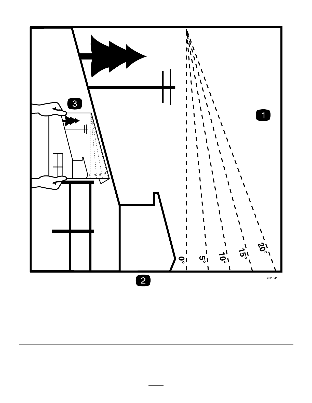
SlopeIndicator
Figure3
Thispagemaybecopiedforpersonaluse.
1.Themaximumslopeyoucansafelyoperatethemachineonis15degrees.Usetheslopecharttodeterminethedegreeofslope
ofhillsbeforeoperating.Donotoperatethismachineonaslopegreaterthan15degrees.Foldalongtheappropriateline
tomatchtherecommendedslope.
2.Alignthisedgewithaverticalsurface,atree,building,fencepole,etc.
3.Exampleofhowtocompareslopewithfoldededge.
7
r:\g011841
Page 8
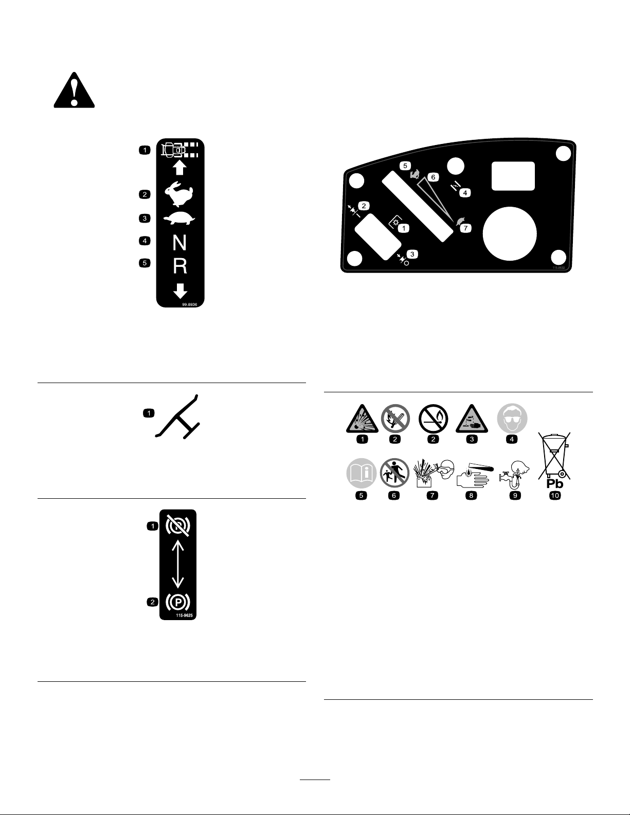
SafetyandInstructionalDecals
Safetydecalsandinstructionsareeasilyvisibletotheoperatorandarelocatednearanyarea
ofpotentialdanger.Replaceanydecalthatisdamagedorlost.
decal115-9632
115-9632
99-8936
1.Machinespeed4.Neutral
2.Fast5.Reverse
3.Slow
Manufacturer'sMark
1.Indicatesthebladeisidentiedasapartfromtheoriginal
machinemanufacturer.
115-9625
1.Parking
brake—disengaged
2.Parkingbrake—engaged
decal99-8936
decaloemmarkt
1.Powertake-off(PTO),
Bladecontrolswitchon
somemodels
2.Bladecontrolswitch—On
3.Bladecontrolswitch—Off7.Slow
4.Choke
5.Fast
6.Continuousvariable
setting
decalbatterysymbols
BatterySymbols
Someorallofthesesymbolsareonyourbattery
1.Explosionhazard
2.Nore,opename,or
smoking.
decal115-9625
3.Causticliquid/chemical
burnhazard
4.Weareyeprotection9.Flusheyesimmediately
5.ReadtheOperator's
Manual.
6.Keepbystandersasafe
distancefromthebattery.
7.Weareyeprotection;
explosivegasescan
causeblindnessandother
injuries
8.Batteryacidcancause
blindnessorsevereburns.
withwaterandgetmedical
helpfast.
10.Containslead;donot
discard.
8
Page 9
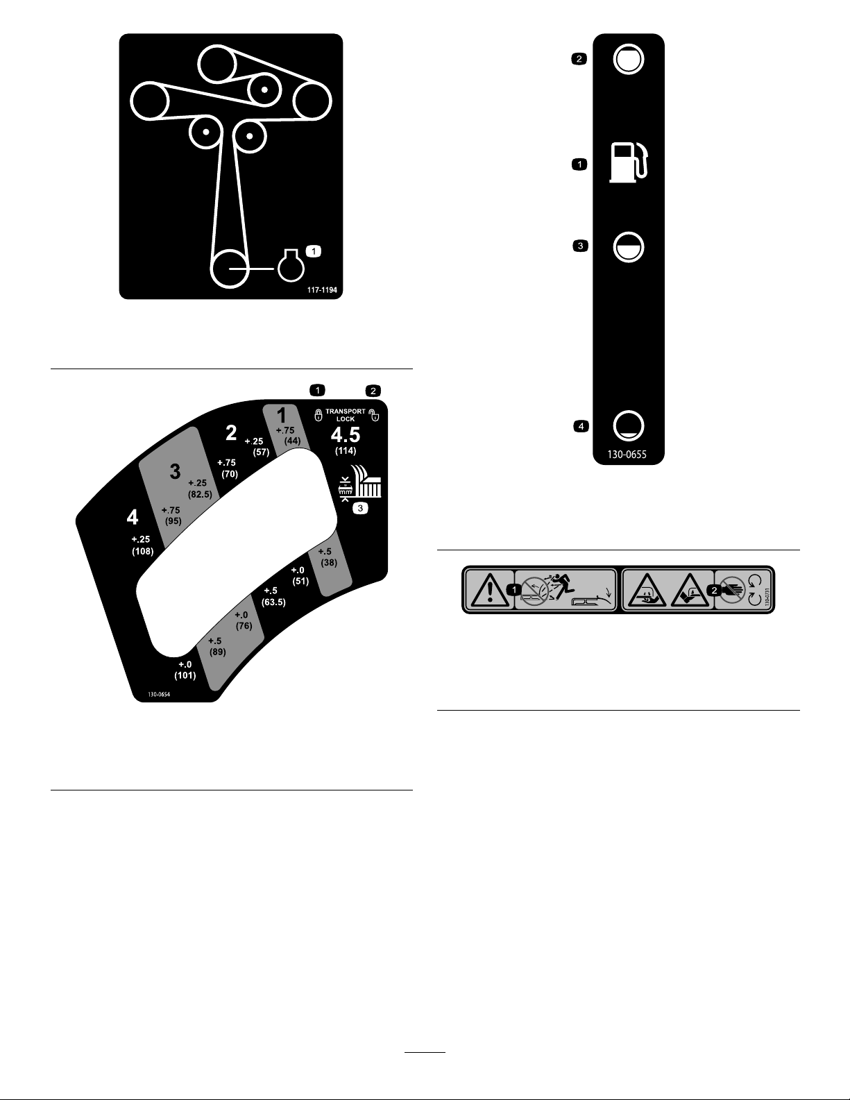
decal117-1 194
117-1194
1.Engine
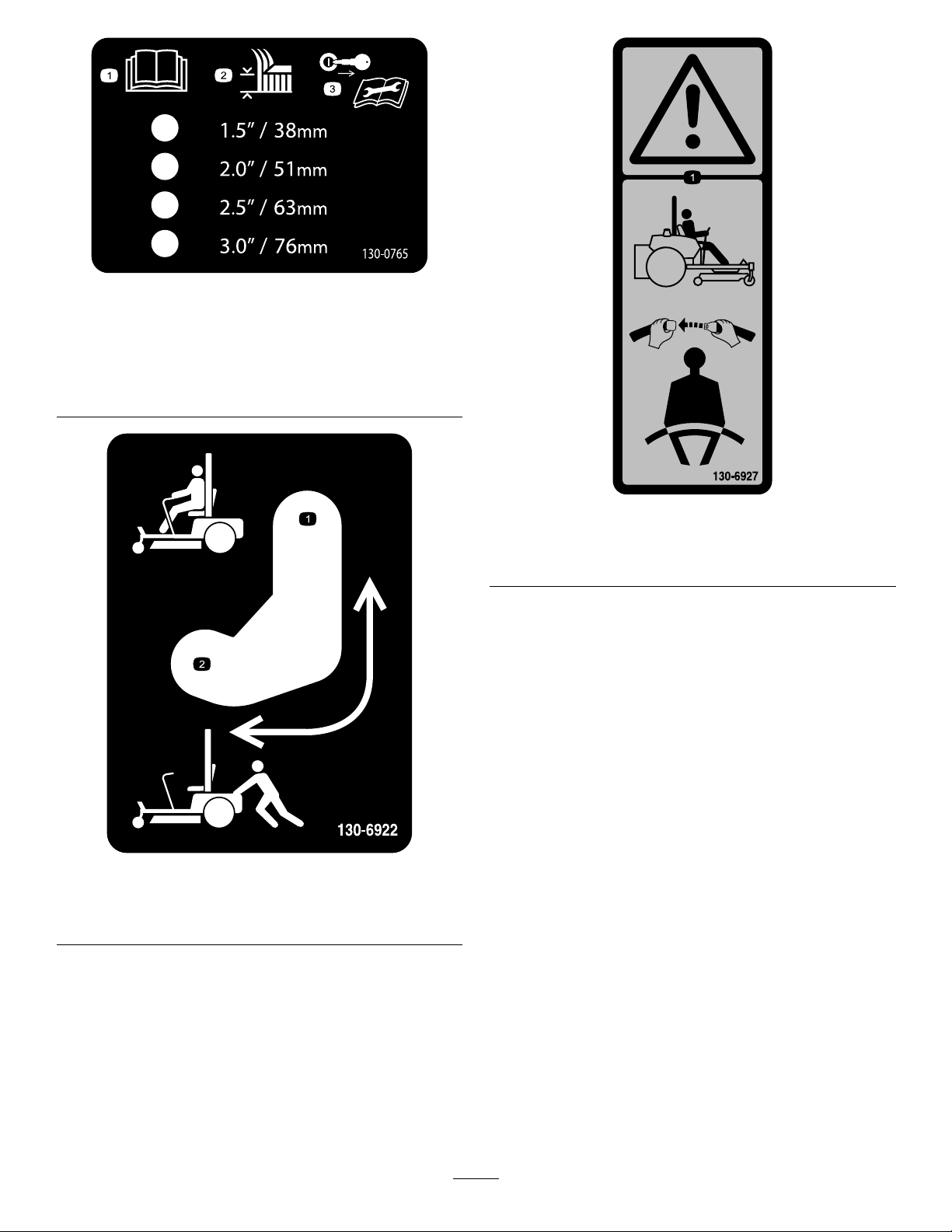
decal130-0655
130-0655
1.Fueltank
3.Half
2.Full4.Empty
decal130-0731
130-0731
1.Warning—thrownobject
hazard;keepthedeector
shieldinplace.
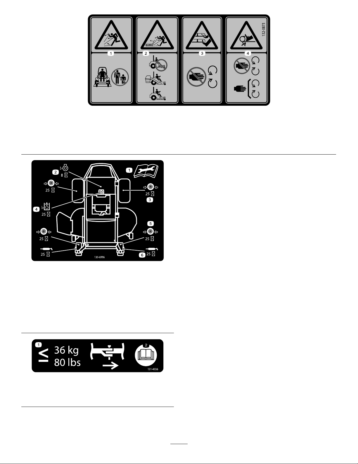
decal130-0654
2.Cuttinghazardofhandor
foot,mowerblade—keep
awayfrommovingparts.
130-0654
1.Transport—lock
2.Transport—unlock
3.Height-of-cut
9
Page 10
decal130-0765
130-0765
1.ReadtheOperator's
Manual.
2.Height-of-cutselection
3.Removethekeyfrom
theignitionandreadthe
Operator'sManualbefore
permorningmaintenance.
decal130-6927
130-6927
1.Warning—alwaysusetheROPSandweartheseatbelt
whenseatedintheoperator'sposition.
1.Bypassleverpositionfor
operatingthemachine.
decal130-6922
130-6922
2.Bypassleverpositionfor
pushingthemachine.
10
Page 11
decal132-0873
132-0873
1.Thrownobjecthazard—keepbystandersawayfromthe
machine.
2.Thrownobjecthazard,mower—donotoperatethewithout
deector,dischargecover,orgrasscollectionsysteminplace.
130-6996
1.ReadtheOperator's
Manualforinformationon
maintenance.
2.Checktheengineoilevery
8hours
3.Checkthedrivewheeltire
pressureevery25hours
4.Checkthehydraulicoil
every25hours
5.Checkthecasterwheel
tirepressureevery25
hours
6.Lubricatethecasterwheel
every25hours
3.Cutting/dismembermentofhandorfoot—stayawayfrom
movingparts.
4.Entanglementhazard,belt—keepallguardsinplace.
decal130-6996
1.Themaximumdrawbar
pullis36kg(80lb).
decal131-4036
131-4036
2.ReadtheOperator's
Manual.
11
Page 12
132-0871
Note:Thismachinecomplieswiththeindustrystandardstabilitytestinthestaticlateralandlongitudinaltestswiththemaximum
recommendedslopeindicatedonthedecal.ReviewtheinstructionsforoperatingthemachineonslopesintheOperator’sManualas
wellastheconditionsinwhichyouwouldoperatethemachinetodeterminewhetheryoucanoperatethemachineinthoseconditions
onthatdayandatthatsite.Changesintheterraincanresultinachangeinslopeoperationforthemachine.Ifpossible,keepthe
cuttingunitsloweredtothegroundwhileoperatingthemachineonslopes.Raisingthecuttingunitswhileoperatingonslopescan
causethemachinetobecomeunstable.
decal132-0871
1.Warning—readtheOperator’sManual;donotoperatethis
machineunlessyouaretrained;wearhearingprotection.
2.Cutting,dismembering,andentanglementhazard—keep
handsawayfrommovingparts;keepallguardsandshieldsin
place.
3.Thrownobjecthazard—keepbystandersaway.6.Tippinghazardonslopes—donotuseonslopesnearopen
4.Ramphazard—whenloadingontoatrailer,donotusedual
ramps;onlyuseasingularrampwideenoughforthemachine
andthathasaninclinelessthan15°;backuptheramp(in
reverse)anddriveforwardofftheramp.
5.Bodilyharmhazard—donotcarrypassengers;lookbehind
youwhenmowinginreverse.
water;donotuseonslopesgreaterthan15°.
12
Page 13
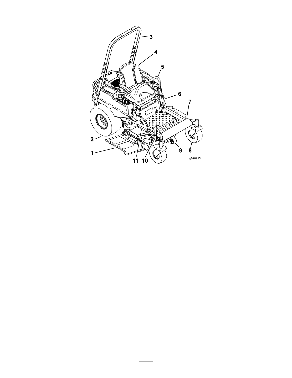
ProductOverview
Figure4
1.Grassdeector4.Operatorseat
2.Drivewheel5.Motion-controllevers8.Frontcasterwheel
3.Rollover-ProtectionSystem
(ROPS)
6.Parkingbrake9.Anti-scalproller
7.Footrest
g028215
10.Mower-deck-liftpedal
11.Height-of-cutlever
13
Page 14
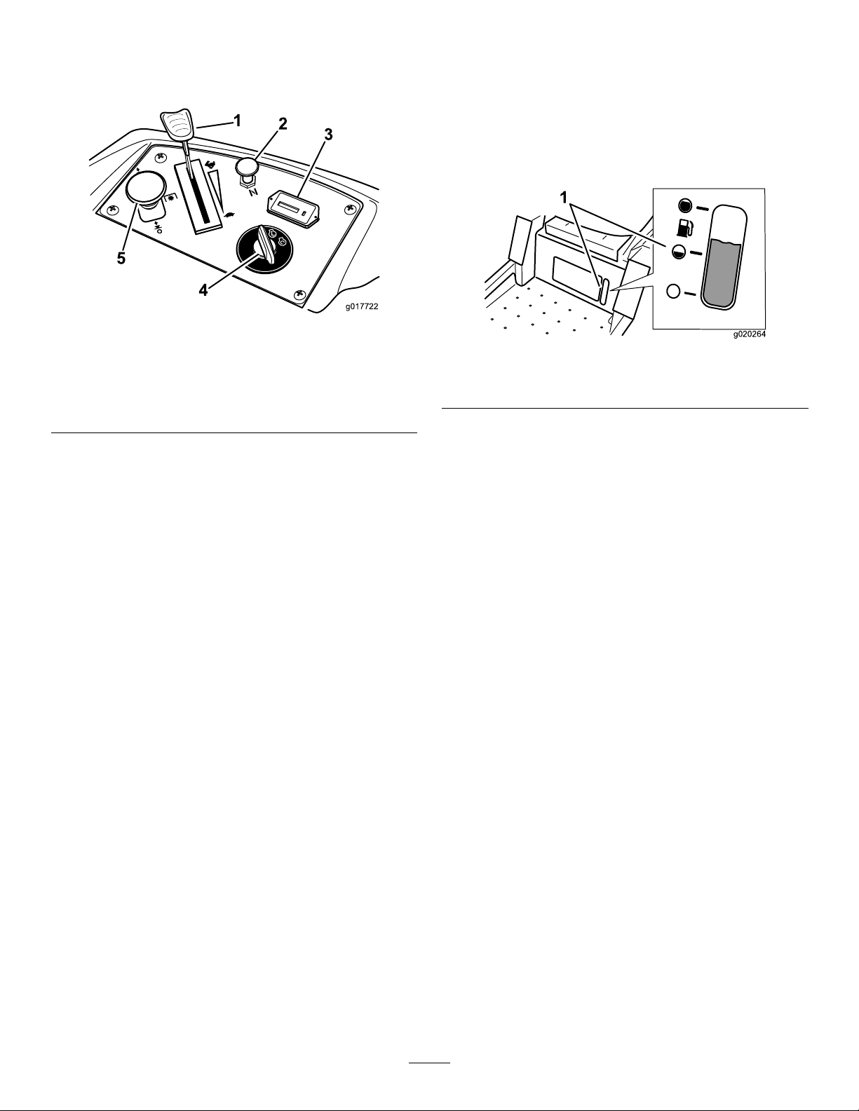
Controls
Becomefamiliarwithallthecontrolsbeforeyoustart
theengineandoperatethemachine(Figure5).
Figure5
1.Throttlecontrol4.Ignitionswitch
2.Choke
3.Hourmeter
5.Blade-controlswitch
(PTO)
switch(PTO)isengaged.Usethesetimesfor
schedulingregularmaintenance(Figure5).
FuelGauge
Thefuelwindowlocatedbelowtheoperatorposition
canbeusedtoverifythelevelofgasolineinthetank
(Figure6).
g017722
g020264
Figure6
1.Fuel-gaugewindow
IgnitionSwitch
Theignitionswitchhas3positions:START,RUN,and
OFF..ThekeywillturntotheSTARTpositionandmove
backtotheRUNpositionuponrelease.Turningthe
keytotheOFFpositionshutsofftheengine;however,
alwaysremovethekeywhenleavingthemachineto
preventtheenginefromaccidentallystarting(Figure
5).
ThrottleControl
ThethrottlecontrolisvariablebetweentheFASTand
SLOWposition.Movingthrottleleverforwardincreases
enginespeedandmovingthrottlelevertotherear
decreasesenginespeed.Movingthethrottleforward
intothedetentisfullthrottle(Figure5).
Choke
Usethechoketostartacoldengine.Pullthechoke
knobuptoengageit.Pushdownonthechokeknob
todisengageit.
Blade-ControlSwitch(Power
Takeoff)
Motion-ControlLevers
Themotion-controlleversarespeed-sensitivecontrols
ofindependent-wheelmotors.Movingaleverforward
orbackwardturnsthewheelonthesamesideforward
orinreverse;wheelspeedisproportionaltothe
amounttheleverismoved.Movethecontrollevers
outwardfromthecentertotheNEUTRAL-LOCKposition
andexitthemachine(Figure4).Alwayspositionthe
motion-controlleversintotheNEUTRAL-LOCKposition
whenyoustopthemachineorleaveitunattended.
Parking-BrakeLever
Theparking-brakeleverislocatedonleftsideofthe
console(Figure4).hebrakeleverengagesaparking
brakeonthedrivewheels.Pulltheleverupand
rearwardtoengagethebrake.Pushtheleverforward
anddowntodisengagethebrake.
FootPedalDeck-LiftSystem
Thefootpedaldeck-liftsystemallowstheoperator
tolowerandraisethedeckfromtheseatedposition.
Theoperatorcanusethefootpedaltoliftthedeck
brieytoavoidobstaclesorlockthedeckinthe
highestheightofcutortransportposition(Figure4).
Theblade-controlswitchengagesanddisengages
powertothemowerblades(Figure5).
HourMeter
Thehourmeterrecordsthenumberofhoursthe
bladesoperate.Itoperateswhentheblade-control
Height-of-CutLever
Theheight-of-cutleverworkswiththefootpedalto
lockthedeckinaspeciccuttingheight.Onlyadjust
theheightofcutwhilemachineisnotmoving(Figure
4).
14
Page 15

Attachments/Accessories
AselectionofT oroapprovedattachmentsand
accessoriesisavailableforusewiththemachineto
enhanceandexpanditscapabilities.Contactyour
AuthorizedServiceDealerorDistributororgoto
www.T oro.comforalistofallapprovedattachments
andaccessories.
Operation
Note:Determinetheleftandrightsidesofthe
machinefromthenormaloperatingposition.
AddingFuel
•Forbestresults,useonlyclean,fresh,unleaded
gasolinewithanoctaneratingof87orhigher
((R+M)/2ratingmethod).
•Oxygenatedfuelwithupto10%ethanolor15%
MTBEbyvolumeisacceptable.
•Donotuseethanolblendsofgasoline(such
asE15orE85)withmorethan10%ethanolby
volume.Performanceproblemsand/orengine
damagemayresultwhichmaynotbecovered
underwarranty.
•Donotusegasolinecontainingmethanol.
•Donotstorefueleitherinthefueltankorfuel
containersoverthewinterunlessafuelstabilizer
isused.
•Donotaddoiltogasoline.
DANGER
Incertainconditionsduringfueling,static
electricitycanbereleasedcausingaspark
whichcanignitethegasolinevapors.Are
orexplosionfromgasolinecanburnyouand
othersandcandamageproperty.
•Alwaysplacegasolinecontainersonthe
groundawayfromyourvehiclebefore
lling.
•Donotllgasolinecontainersinsidea
vehicleoronatruckortrailerbedbecause
interiorcarpetsorplastictruckbedliners
mayinsulatethecontainerandslowthe
lossofanystaticcharge.
•Whenpractical,removegas-powered
equipmentfromthetruckortrailerand
refueltheequipmentwithitswheelsonthe
ground.
•Ifthisisnotpossible,thenrefuelsuch
equipmentonatruckortrailerfroma
portablecontainer,ratherthanfroma
gasolinedispensernozzle.
•Ifagasolinedispensernozzlemustbe
used,keepthenozzleincontactwiththe
rimofthefueltankorcontaineropeningat
alltimesuntilfuelingiscomplete.
15
Page 16
WARNING
Gasolineisharmfulorfatalifswallowed.
Long-termexposuretovaporscancause
seriousinjuryandillness.
•Avoidprolongedbreathingofvapors.
•Keepfaceawayfromnozzleandgastank
orconditioneropening.
•Keepgasawayfromeyesandskin.
Addthecorrectamountofgasstabilizer/conditioner
tothegas.
Note:Afuelstabilizer/conditionerismosteffective
whenmixedwithfreshgasoline.T ominimizethe
chanceofvarnishdepositsinthefuelsystem,usefuel
stabilizeratalltimes.
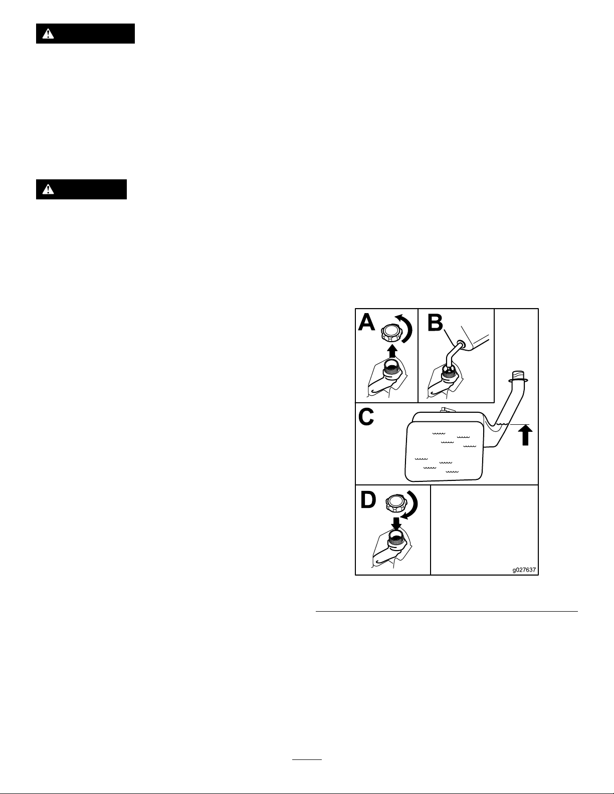
FillingtheFuelTank
Shutofftheengineandmovethemotioncontrolsto
thePARKposition.
DANGER
Incertainconditions,gasolineisextremely
ammableandhighlyexplosive.Areor
explosionfromgasolinecanburnyouand
othersandcandamageproperty.
•Fillthefueltankoutdoors,inanopenarea,
whentheengineiscold.Wipeupany
gasolinethatspills.
•Neverllthefueltankinsideanenclosed
trailer.
•Donotllthefueltankcompletelyfull.Add
gasolinetothefueltankuntilthelevelis6
to13mm(1/4to1/2inch)belowthebottom
ofthellerneck.Thisemptyspaceinthe
tankallowsgasolinetoexpand.
•Neversmokewhenhandlinggasoline,and
stayawayfromanopenameorwhere
gasolinefumesmaybeignitedbyaspark.
•Storegasolineinanapprovedcontainer
andkeepitoutofthereachofchildren.
Neverbuymorethana30-daysupplyof
gasoline.
Important:Donotoverllfueltank.Fillthefuel
tanktothebottomofthellerneck.Theempty
spaceinthetankallowsthefueltoexpand.
Overllingmayresultinfuelleakageordamageto
theengineoremissionsystem.
1.Cleanaroundthefuel-tankcapandremovethe
cap.
2.Slowlyaddregular,unleadedgasolineuntilthe
fuelreachesthebaseofthellerneck(Figure7).
•Donotoperatewithoutentireexhaust
systeminplaceandinproperworking
condition.
UsingStabilizer/Conditioner
Useafuelstabilizer/conditionerinthemachineto
providethefollowingbenets:
•Keepsgasolinefreshduringstorageof90daysor
less.Forlongerstorageitisrecommendedthat
thefueltankbedrained.
•Cleanstheenginewhileitruns
•Eliminatesgum-likevarnishbuildupinthefuel
system,whichcauseshardstarting
Important:Donotusefueladditivescontaining
methanolorethanol.
g027637
Figure7
3.Installthefuel-tankcapsecurelyandtighten
untilitclicks.
Note:Wipeupanygasolinethatmayhave
spilled.
16
Page 17

ThinkSafetyFirst
CAUTION
Pleasereadallsafetyinstructionsandsymbolsinthe
safetysection.Knowingthisinformationcouldhelp
youorbystandersavoidinjury.
DANGER
Operatingthemachineonwetgrassorsteep
slopescancauseslidingandlossofcontrol.
•Donotoperateonslopesgreaterthan15
degrees.
•Reducespeedanduseextremecautionon
slopes.
•Donotoperatethemachinenearwater.
DANGER
Wheelsdroppingoveredgescancause
rollovers,whichmayresultinseriousinjury,
death,ordrowning.
Donotoperatethemachineneardrop-offs.
Thismachineproducessoundlevelsin
excessof85dBAattheoperatorsearandcan
causehearinglossthroughextendedperiods
ofexposure.
Wearhearingprotectionwhenoperatingthis
machine.
Wearprotectiveequipmentforyoureyes,ears,hands,
andfeetwhenusingthismachine(Figure9).
g009027
Figure9
1.Weareyeprotection.2.Wearhearingprotection.
Usingthe
DANGER
Operatingthemachinewhiletherollbaris
downmayleadtoseriousinjuryordeathin
theeventofarollover.
Alwayskeeptherollbarinthefullyraisedand
lockedpositionandusetheseatbelt.
Figure8
Rollover-ProtectionSystem
(ROPS)
WARNING
Toavoidinjuryordeathfromrollover:keep
therollbarinstalledandusetheseatbelt.
WARNING
Thereisnorolloverprotectionwhentheroll
barisremoved.
•Driveslowlyandcarefully.
•Checkcarefullyforoverheadclearances
(i.e.,branches,doorways,electricalwires)
beforedrivingunderanyobjectsanddo
notcontactthem.
g000963
1.Safezone—usethe
machinehere.
2.Useawalk-behindmower
and/orhandtrimmernear
drop-offsandwater.
3.Water
17
Page 18

Understandingthe
CheckingtheEngine-Oil
Safety-InterlockSystem
WARNING
Ifthesafety-interlockswitchesare
disconnectedordamaged,themachinecould
operateunexpectedly,causingpersonal
injury.
•Donottamperwiththeinterlockswitches.
•Checktheoperationoftheinterlock
switchesdailyandreplaceanydamaged
switchesbeforeoperatingthemachine.
Thesafety-interlocksystemisdesignedtopreventthe
enginefromstartingunless:
•Thebladesaredisengaged.
•Themotion-controlleversareinthePARKposition.
Thesafety-interlocksystemalsoisdesignedtoshut
offtheenginewheneverthecontrolleversareoutof
thePARKpositionandyourisefromtheseat.
Level
Beforeyoustarttheengineandusethemachine,
checktheoillevelintheenginecrankcase;referto
CheckingtheEngine-OilLevel(page32).
BreakinginaNewMachine
Newenginestaketimetodevelopfullpower.Mower
decksanddrivesystemshavehigherfrictionwhen
new,placingadditionalloadontheengine.Allow
40to50hoursofbreak-intimefornewmachinesto
developfullpowerandbestperformance.
OperatingtheParking Brake
Alwayssettheparkingbrakewhenyoustopthe
machineorleaveitunattended.
SettingtheParkingBrake
TestingtheSafety-Interlock System
Testthesafety-interlocksystembeforeyouusethe
machineeachtime.Ifthesafetysystemdoesnot
operateasdescribedbelow,haveanAuthorized
ServiceDealerrepairthesafetysystemimmediately .
1.Whilesittingontheseat,withthecontrollevers
inthePARKposition,andmovetheblade-control
switchtotheONposition.Trystartingthe
engine;theengineshouldnotstart.
2.Whilesittingontheseat,movetheblade-control
switchtotheOFFposition.Moveeithermotion
controllevertothecenter,unlockedposition.
Trystartingtheengine;theengineshouldnot
start.Repeatwiththeothermotion-controllever.
3.Whilesittingontheseat,movetheblade
controlswitchtotheOFFposition,andlockthe
motion-controlleversinthePARKposition.Start
theengine.Whiletheengineisrunning,engage
theblade-controlswitch,andriseslightlyfrom
theseat;theengineshouldshutoff.
g027638
Figure10
ReleasingtheParkingBrake
4.Whilesittingontheseat,movetheblade-control
switchtotheOFFposition,andlockthe
motion-controlleversinthePARKposition.Start
theengine.Whiletheengineisrunning,move
themotion-controlleverstothecenter,unlocked
position,engagetheblade-controlswitch,and
riseslightlyfromtheseat;theengineshould
shutoff.
g027639
Figure11
18
Page 19

OperatingtheThrottle
OperatingtheIgnition
ThethrottlecontrolcanbemovedbetweentheSLOW
andFASTpositions(Figure12).
AlwaysusetheFASTpositionwhenturningonthe
mowerdeckwiththeblade-controlswitch(PTO).
Figure12
OperatingtheChoke
Usethechoketostartacoldengine.
1.Iftheengineiscold,usethechoketostartthe
engine.
2.Pulluponthechokeknobtoengagethechoke
beforeusingtheignitionswitch(Figure13).
3.Pushdownonthechoketodisengagethechoke
aftertheenginestarts(Figure13).
Switch
1.TurntheignitionkeytotheSTARTposition
(Figure14).
Note:Whentheenginesstarts,releasethekey.
Note:Additionalstartingcyclesmaybe
requiredwhenstartingtheenginefortherst
timeafterthefuelsystemhasbeenwithoutfuel
completely.
g028222
g008947
Figure14
2.TurntheignitionkeytotheSTOPposition.
Figure13
1.ONposition2.OFFposition
StartingandStoppingthe Engine
StartingtheEngine
StarttheengineasshowninFigure15.
Note:Awarmorhotenginemaynotrequirechoking.
Important:Donotengagestarterformorethan5
secondsatatime.Iftheenginefailstostartallow
a15secondcool-downperiodbetweenattempts.
Failuretofollowtheseinstructionscanburnout
thestartermotor.
Note:Ifthefuelsystemwasdepletedoffuel—add
fueltothemachineanduseadditionalstartingcycles
whenstartingtheengine.
g008959
19
Page 20

Figure15
g028224
Figure16
g028223
Operatingthe
Blade-ControlSwitch
StoppingtheEngine
CAUTION
Injurycanoccurifchildrenorbystanders
moveorattempttooperatethemachinewhile
itisunattended.
Alwaysremovetheignitionkeyandsetthe
parkingbrakewhenleavingthemachine
unattended,evenifjustforafewminutes.
StoptheengineasshowninFigure16.
(PTO)
Theblade-controlswitch(PTO)startsandstopsthe
mowerbladesandanypoweredattachments.
EngagingtheBlade-Control Switch(PTO)
Engagetheblade-controlswitch(PTO)withthe
throttlepositionatFAST.
Note:Engagingtheblade-controlswitch(PTO)with
thethrottlepositionathalforlesswillcauseexcessive
weartothedrivebelts.
20
Page 21

DisengagingtheBlade-Control Switch(PTO)
g008945
Figure17
Figure18
DrivingtheMachine
Thethrottlecontrolregulatestheenginespeedas
measuredinrpm(revolutionsperminute).Place
thethrottlecontrolintheFASTpositionforbest
performance.Alwaysoperateinthefull-throttle
positionwhenmowing.
CAUTION
Machinecanspinveryrapidly.Operatormay
losecontrolofmachineandcausepersonal
injuryordamagetomachine.
•Usecautionwhenmakingturns.
•Slowthemachinedownbeforemaking
sharpturns.
g009174
Figure19
1.Motion-control
lever—NEUTRAL-LOCK
position
2.Center,unlockedposition5.Frontofthemachine
3.Forward
4.Backward
g004532
DrivingForward
Note:Theenginekillsifthetraction-controllevers
aremovedwiththeparkingbrakeengaged.
1.Releasetheparkingbrake.
2.Movetheleverstothecenter,unlockedposition.
3.Tomoveforward,slowlypushthemotion-control
leversforward(Figure20).
UsingtheMotion-ControlLevers
Usethemotion-controlleversasshowninFigure19.
21
Page 22

StoppingtheMachine
WARNING
Childrenorbystandersmaybeinjuredifthey
moveorattempttooperatethemachinewhile
itisunattended.
Alwaysremovetheignitionkeyandmove
themotion-controlleversoutwardtothe
PARKpositionwhenleavingthemachine
unattended,evenifjustforafewminutes.
Tostopthemachine,movethetraction-controllevers
totheNEUTRALpositionandmovetothelocked
position,disengagetheblade-controlswitch(PTO),
andturntheignitionkeytotheOFFposition.
Settheparkingbrakewhenyouleavethemachine.
Remembertoremovethekeyfromtheignitionswitch.
Figure20
DrivingBackward
Note:Alwaysusecautionwhenbackingupand
turning.
1.Movetheleverstothecenter,unlockedposition.
2.Togobackward,slowlypullthemotion-control
leversrearward(Figure21).
g008952
AdjustingtheHeightofCut
Themachineisequippedwithafootpedaldeck-lift
system.Theoperatorcanusethefootpedaltolift
thedeckbrieytoavoidobstaclesorlockthedeckin
thehighestheightofcutortransportposition.The
operatorcanusetheheight-of-cutleverwiththefoot
pedaltolockthedeckinaspeciccuttingheight.
UsingtheFootPedalDeck-Lift System
•Pressthepedaldowntoraisethedeck;continue
topressthepedaluntilthedeckislockedinthe
transportposition(Figure22).
•Pushonthedeck-liftpedalwithyourfootandpull
thetransportlockhandlerearwardtodisengage
thetransportlock(Figure22).
Figure21
g008953
22
Page 23

Figure22
TransportLockPosition
AdjustingtheHeightofCut
Theheightofcutcanbeadjustedfrom38to114mm
(1-1/2to4-1/2inch)in6mm(1/4inch)increments
byrelocatingtheheight-of-cutpinintodifferenthole
locations.
1.Pushonthedeck-liftpedalwithyourfootand
raisethemowerdecktothetransport-lock
position(alsothe114mm(4-1/2inch)cutting
heightposition)asshowninFigure23.
2.Toadjust,removethepinfromtheheight-of-cut
bracket(Figure23).
3.Selectaholeintheheight-of-cutsystem
correspondingtothedesiredheightofcutand
insertthepin(Figure23).
g024410
Figure23
1.Deck-liftpedal3.Height-of-cutpositions
g024409
2.Handle4.Pin
AdjustingtheAnti-Scalp Rollers
Wheneveryouchangetheheightofcut,itis
recommendedtoadjusttheheightoftheanti-scalp
rollers.
1.Disengagetheblade-controlswitch(PTO),move
themotion-controlleverstotheNEUTRAL-LOCK
position,andsettheparkingbrake.
2.Shutofftheengine,removethekey ,andwait
forallmovingpartstostopbeforeleavingthe
operatingposition.
3.Removetheangenut,anti-scalproller,andbolt
fromthebracket(Figure24).
Note:Keeptheboltandanti-scalproller
togetherwhenremoving.
4.Pushonthedeck-liftpedalwithyourfootand
pullthehandlerearwardtodisengagethe
transportlock(Figure22).
5.Lowerthedeckslowlyuntilthelevermakes
contactwiththepin.
1.Flangenut4.Bushing
2.Spacer
3.Anti-scalproller
23
g024312
Figure24
5.Bolt
Page 24

4.Aligntheboltandanti-scalprollerinthe
holeofthebracketthatmatchedtheclosest
height-of-cutposition(Figure24).
5.Inserttheboltintothebracketholeandsecure
theboltandanti-scalprollerwiththeangenut
(Figure24).
PositioningtheSeat
Theseatcanmoveforwardandbackward(Figure25).
Positiontheseatwhereyouhavethebestcontrolof
themachineandaremostcomfortable.
g027252
Figure26
AdjustingtheTilt
Themotion-controlleverscanbetiltedforwardor
rearwardformaximumoperatorcomfort.
1.Loosentheupperboltholdingthecontrollever
tothecontrol-armshaft.
Figure25
Adjustingthe Motion-ControlLevers
AdjustingtheHeight
Note:Repeattheadjustmentfortheoppositecontrol
lever.
Themotion-controlleverscanbeadjustedhigheror
lowerformaximumoperatorcomfort(Figure26).
2.Loosenthelowerboltjustenoughtopivotthe
controlleverforwardorrearward.
3.Tightenbothboltstosecurethecontrolinthe
newposition.
g027632
4.Repeattheadjustmentfortheoppositecontrol
lever.
PushingtheMachineby Hand
Important:Alwayspushthemachinebyhand.
Nevertowthemachinebecausedamagemay
occur.
1.Parkthemachineonalevelsurfaceand
disengagethebladecontrolswitch.
2.Movethemotioncontrolleversoutwardto
neutrallockposition,shutofftheengine,remove
thekey,andwaitforallmovingpartstostop
beforeleavingtheoperatingposition.Makesure
theparkingbrakeisdisengaged.
3.Dothisprocedureoneachsideofthe
machineFigure27.
24
Page 25

Figure27
4.Movethebypasstothepositionforoperating
themachine(Figure27)toengagethewheel
motors.
UsingtheSideDischarge
Themowerhasahingedgrassdeectorthat
dispersesclippingstothesideanddowntowardthe
turf.
DANGER
Withoutagrassdeector,dischargecover,or
completegrasscatcherassemblymountedin
place,youandothersareexposedtoblade
contactandthrowndebris.Contactwith
rotatingmowerblade(s)andthrowndebris
willcauseinjuryordeath.
•Neverremovethegrassdeectorfrom
themowerbecausethegrassdeector
routesmaterialdowntowardtheturf.Ifthe
g027642
grassdeectoriseverdamaged,replaceit
immediately.
•Neverputyourhandsorfeetunderthe
mower.
•Nevertrytoclearthedischargearea
ormowerbladesunlessyoumovethe
blade-controlswitch(PTO)totheOFF
position,rotatetheignitionkeytotheOFF
position,andremovethekey .
•Makesurethatthegrassdeectorisinthe
downposition.
25
Page 26
TransportingtheMachine
Useaheavy-dutytrailerortrucktotransportthe
machine.Ensurethatthetrailerortruckhasall
necessarybrakes,lighting,andmarkingasrequired
bylaw.Pleasecarefullyreadallthesafetyinstructions.
Knowingthisinformationcouldhelpyou,yourfamily,
pets,orbystandersavoidinjury.
g028043
Figure29
WARNING
Drivingonthestreetorroadwaywithout
turnsignals,lights,reectivemarkings,ora
slow-moving-vehicleemblemisdangerous
andcanleadtoaccidents,causingpersonal
injury.
Donotdrivethemachineonapublicstreet
orroadway.
1.Ifyouareusingatrailer,connectittothetowing
vehicleandconnectthesafetychains.
2.Ifapplicable,connectthetrailerbrakes.
3.Loadthemachineontothetrailerortruck.
4.Shutofftheengine,removethekey,setthe
brake,andclosethefuelvalve.
5.Tiedownthemachinenearthefrontcaster
wheelsandtherearbumper(Figure28).
1.Backthemachineupthe
ramp.
2.Drivethemachineforward
downtheramp.
Important:Donotusenarrowindividualramps
foreachsideofthemachine.
Ensuretherampislongenoughsothattheanglewith
thegrounddoesnotexceed15degrees(Figure30).
Onatground,thisrequiresaramptobeatleast4
timesaslongastheheightofthetrailerortruckbed
totheground.Asteeperanglemaycausemower
componentstogetcaughtastheunitmovesfromthe
ramptothetrailerortruck.Steeperanglesmayalso
causethemachinetotiporlosecontrol.Ifloadingon
ornearaslope,positionthetrailerortrucksothatitis
onthedownsideoftheslopeandtherampextends
uptheslope.Thiswillminimizetherampangle.
WARNING
Loadingamachineontoatrailerortruck
increasesthepossibilityoftip-overandcould
causeseriousinjuryordeath.
•Useextremecautionwhenoperatinga
machineonaramp.
Figure28
LoadingtheMachine
Useextremecautionwhenloadingorunloading
machinesontoatraileroratruck.Useafull-width
rampthatiswiderthanthemachineforthisprocedure.
Backthemachineuptherampanddriveitforward
downtheramp(Figure29).
•Useonlyafull-widthramp;donotuse
individualrampsforeachsideofthe
machine.
g027708
•Donotexceeda15-degreeanglebetween
therampandthegroundorbetweenthe
rampandthetrailerortruck.
•Ensurethelengthoframpisatleast4
timesaslongastheheightofthetrailer
ortruckbedtotheground.Thiswill
ensurethatrampangledoesnotexceed15
degreesonatground.
•Backuprampsanddriveforwarddown
ramps.
•Avoidsuddenaccelerationordeceleration
whiledrivingthemachineonarampas
thiscouldcausealossofcontrolora
tip-oversituation.
26
Page 27

Figure30
g027996
1.Full-widthrampinstowed
position
2.Sideviewoffull-width
rampinloadingposition
3.Notgreaterthan
15degrees
4.Rampisatleast4times
aslongastheheightof
thetrailerortruckbedto
theground
5.H=heightofthetraileror
truckbedtotheground
6.Trailer
27
Page 28

OperatingTips
UsingtheFastThrottleSetting
raisethecuttingheighthigherthanusualandcutthe
grassatthissetting.Thencutthegrassagainusing
thelower,normalsetting.
Forbestmowingandmaximumaircirculation,operate
theengineattheFASTposition.Airisrequiredto
thoroughlycutgrassclippings,sodonotsetthe
height-of-cutsolowastototallysurroundthemower
inuncutgrass.Alwaystrytohave1sideofthemower
freefromuncutgrass,whichallowsairtobedrawn
intothemower.
CuttingaLawnfortheFirstTime
Cutgrassslightlylongerthannormaltoensurethat
thecuttingheightofthemowerdoesnotscalpany
unevenground.However,thecuttingheightusedin
thepastisgenerallythebestonetouse.Whencutting
grasslongerthan15cm(6inches)tall,youmaywant
tocutthelawntwicetoensureanacceptablequality
ofcut.
CuttingaThirdoftheGrassBlade
Itisbesttocutonlyaboutathirdofthegrassblade.
Cuttingmorethanthatisnotrecommendedunless
grassissparse,oritislatefallwhengrassgrows
moreslowly.
AlternatingtheMowingDirection
Alternatethemowingdirectiontokeepthegrass
standingstraight.Thisalsohelpsdisperseclippings
whichenhancesdecompositionandfertilization.
Stopping
Ifyoumuststoptheforwardmotionofthemachine
whilemowing,aclumpofgrassclippingsmay
dropontoyourlawn.Toavoidthis,moveontoa
previouslycutareawiththebladesengagedoryou
candisengagethemowerdeckwhilemovingforward.
KeepingtheUndersideofthe
MowerClean
Cleanclippingsanddirtfromtheundersideofthe
moweraftereachuse.Ifgrassanddirtbuildupinside
themower,cuttingqualitywilleventuallybecome
unsatisfactory.
MaintainingtheBlade(s)
Maintainasharpbladethroughoutthecuttingseason
becauseasharpbladecutscleanlywithouttearingor
shreddingthegrassblades.Tearingandshredding
turnsgrassbrownattheedges,whichslowsgrowth
andincreasesthechanceofdisease.Checkthe
mowerbladesaftereachuseforsharpness,and
foranywearordamage.Filedownanynicksand
sharpenthebladesasnecessary .Ifabladeis
damagedorworn,replaceitimmediatelywitha
genuineT ororeplacementblade.
MowingatCorrectIntervals
Grassgrowsatdifferentratesatdifferenttimesof
theyear.Tomaintainthesamecuttingheight,mow
moreofteninearlyspring.Asthegrassgrowthrate
slowsinmidsummer,mowlessfrequently.Ifyou
cannotmowforanextendedperiod,rstmowata
highcuttingheight,thenmowagain2dayslaterata
lowerheightsetting.
UsingaSlowerCuttingSpeed
Toimprovecutquality ,useaslowergroundspeed
incertainconditions.
AvoidingCuttingTooLow
Whenmowinguneventurf,raisethecuttingheight
toavoidscalpingtheturf.
CuttingLongGrass
Ifthegrassiseverallowedtogrowslightlylongerthan
normal,orifitcontainsahighdegreeofmoisture,
28
Page 29

Maintenance
RecommendedMaintenanceSchedule(s)
MaintenanceService
Interval
Aftertherst50hours
Beforeeachuseordaily
Aftereachuse
Every25hours
Every50hours
Every100hours
Every400hours
MaintenanceProcedure
•Changethehydrauliclteranduid.
•Checkthesafety-interlocksystem.
•Checktheaircleanerfordirty,looseordamagedparts.
•Checktheengine-oillevel.
•Cleantheblowerhousing(moreoftenunderextremelydusty,dirtyconditions).
•Checkthemowerblades.
•Inspectthegrassdeectorfordamage.
•Cleanthemowerhousing.
•Greasealllubricationpoints.
•Serviceorreplacetheair-cleanerfoamelement(moreoftenunderextremelydusty,
dirtyconditions).
•Checktirepressure.
•Checkthehydraulic-uidlevelintheexpansiontank.
•Inspectthebeltsforcracksandwear.
•Replacetheair-cleanerpaperelement(moreoftenunderextremelydusty,dirty
conditions).
•Changetheengineoilandtheengine-oillter.
•Cleanthecoolingns(moreoftenunderextremelydusty ,dirtyconditions).
•Replacethefuellter(moreoftenunderdusty ,dirtyconditions).
•Changethehydrauliclteranduid.
Every500hours
Monthly
Yearlyorbeforestorage
•Replacethesparkplug(s).
•Checkthebatterycharge.
•Paintchippedsurfaces.
•Checkallmaintenanceprocedureslistedabovebeforestorage.
Important:Refertoyourengineoperator'smanualforadditionalmaintenanceprocedures.
CAUTION
Ifyouleavethekeyintheignitionswitch,someonecouldaccidentlystarttheengineand
seriouslyinjureyouorotherbystanders.
Removethekeyfromtheignitionanddisconnectthewirefromthesparkplugbeforeyoudo
anymaintenance.Setthewireasidesothatitdoesnotaccidentallycontactthesparkplug.
29
Page 30

Pre-Maintenance
Procedures
Service-IntervalChart
decal130-6996
Figure31
Locatedontheseatpanunderside
1.ReadtheOperator'sManualbeforeperformingany
maintenance.
2.Checktheengineoilevery8hours.5.Checkthecasterwheeltirepressureevery25hours.
3.Checkthedrivewheeltirepressureevery25hours.
4.Checkthehydraulicoilevery25hours.
6.Lubricatethecasterwheelevery25hours.
RaisingtheSeat
Ensurethatthemotion-controlleversarelockedinthe
NEUTRAL-LOCKpositionandlifttheseatforward.
Thefollowingcomponentscanbeaccessedbyraising
theseat:
•Servicedecal
•Fuses
•Batteryandcables
30
Page 31

Lubrication
EngineMaintenance
GreasingtheBearings
ServiceInterval:Every25hours—Greaseall
lubricationpoints.
GreaseType:No.2lithiumgrease
1.Parkthemachineonalevelsurfaceand
disengagetheblade-controlswitch.
2.Movethemotion-controlleversoutwardtothe
NEUTRAL-LOCKposition,shutofftheengine,
removethekey,andwaitforallmovingpartsto
stopbeforeleavingtheoperatingposition.
3.Cleanthegreasettings(Figure32andFigure
31)witharag.
Note:Makesuretoscrapeanypaintoffthe
frontofthetting(s).
WARNING
Contactwithhotsurfacesmaycausepersonal
injury.
Keephands,feet,face,clothingandother
bodypartsawaythemuferandotherhot
surfaces.
ServicingtheAirCleaner
ServiceInterval:Beforeeachuseordaily—Check
theaircleanerfordirty,looseor
damagedparts.
Every25hours—Serviceorreplacethe
air-cleanerfoamelement(moreoftenunder
extremelydusty,dirtyconditions).
Every100hours—Replacetheair-cleaner
paperelement(moreoftenunderextremely
dusty,dirtyconditions).
Thisengineisequippedwithareplaceable,
high-densitypaperandfoamair-cleanerelement.
Checktheaircleanerdailyorbeforestartingthe
engine.Checkforabuildupofdirtanddebrisaround
theair-cleanersystem.Keepthisareaclean.Also,
checkforlooseordamagedcomponents.Replaceall
bentordamagedair-cleanercomponents.
Figure32
1.Frontcastertire
4.Connectagreaseguntoeachttingandpump
greaseintothettingsuntilgreasebeginsto
oozeoutofthebearings(Figure31andFigure
32).
Note:Operatingtheenginewithlooseordamaged
air-cleanercomponentscouldallowunlteredairinto
theengine,causingprematurewearandfailure.
Note:Servicetheaircleanermoreoftenunder
extremelydusty,dirtyconditions.
g009949
RemovingtheElements
1.Rotatethelatchesoutward.
2.Removethecovertoaccesstheair-cleaner
elements(Figure33).
31
Page 32

donotuseifthesealingsurfacesarebentor
damaged.
2.Cleantheair-cleanerbaseasrequired,and
checkthecondition.
InstallingtheElements
1.Installthefoamelementontothepaperelement.
2.Installtheelementsontotheair-cleanerbase
(Figure34).
3.Installthecover,andsecureitwiththelatches
(Figure33).
Figure33
1.Air-cleanercover2.Air-cleanerlatch
3.Removethefoamandpaperelements(Figure
34).
4.Removethefoamelementfromthepaper
element(Figure34).
Figure34
1.Air-cleanercover3.Paperelement
2.Foamelement
g028105
ServicingtheEngineOil
OilType:Detergentoil(APIserviceSJorhigher)
CrankcaseCapacity:1.9L(64oz)whenthelter
ischanged
Viscosity:Seethetablebelow.
g028106
g017552
Figure35
ServicingtheFoamElement
1.Washthefoamelementinwarmwaterand
detergent.
2.Rinseandallowittoairdry.
3.Lightlyoilthefoamelementwithnewoiland
squeezeoutexcessoil.
ServicingthePaperElement
1.Gentlytapthepaperelementtodislodgedirt.
Note:Donotwashthepaperelementoruse
pressurizedair,asthiswilldamagetheelement.
Note:Replaceadirty,bent,ordamaged
element.Handlethenewelementcarefully;
CheckingtheEngine-OilLevel
ServiceInterval:Beforeeachuseordaily—Check
theengine-oillevel.
1.Parkthemachineonalevelsurface,disengage
theblade-controlswitch,shutofftheengine,
andremovethekey.
2.Makesurethattheengineisstopped,level,and
iscool,sotheoilhastimetodrainintothesump.
3.Checktheengine-oillevel(Figure36).
32
Page 33

Figure36
ChangingtheEngineOilandthe Engine-OilFilter
ServiceInterval:Every100hours—Changethe
engineoilandtheengine-oillter.
Note:Thedrainplugisattachedtothedrainhose.
Note:Disposeoftheusedoilatarecyclingcenter.
Fillwithoilasspeciedinthe“ViscosityGrades”table
(Figure35).
1.Parkthemachine,sothatthedrainsideis
slightlylowerthantheoppositeside,toensure
thattheoildrainscompletely.
2.Disengagetheblade-controlswitchandmove
themotioncontrolsoutwardtothePARKposition.
3.Shutofftheengine,removethekey ,andwait
forallmovingpartstostopbeforeleavingthe
operatingposition.
g027515
g027934
Figure37
4.Torquetheplugto14N•m(10ft-lb).
5.Changetheengine-oillterasshowninFigure
38.
33
Page 34

Figure39
ServicingtheSparkPlug
ServiceInterval:Every500hours—Replacethe
sparkplug(s).
g027517
Figure38
6.Slowlypourapproximately80%ofthespecied
oilintothellertube(Figure39).
g028127
ThesparkplugisRFIcompliant.Equivalentalternate
brandplugscanalsobeused.
Type:ChampionXC12YC
AirGap:0.76mm(0.03inch)
RemovingtheSparkPlug
1.Disengagetheblade-controlswitch,movethe
motioncontrolsoutwardtotheparkposition,
shutofftheengine,andremovethekey .
2.Beforeremovingthesparkplug(s),cleanthe
areaaroundthebaseoftheplugtokeepdirt
anddebrisoutoftheengine.
3.Removethesparkplug(Figure40).
34
Page 35

g027478
Figure40
CheckingtheSparkPlug
Important:Donotcleanthesparkplug(s).
Alwaysreplacethesparkplug(s)whenithas:a
blackcoating,wornelectrodes,anoilylm,or
cracks.
Note:Ifyouseelightbrownorgrayontheinsulator,
theengineisoperatingproperly.Ablackcoatingon
theinsulatorusuallymeanstheaircleanerisdirty.
Setthegapto0.76mm(0.03inch).
InstallingtheSparkPlug
Tightenthesparkplugto27N•m(20ft-lb)asshown
inFigure42.
g028109
Figure42
Figure41
CleaningtheBlower Housing
Every100hours/Yearly(whichevercomesrst)
g027479
Toensurepropercooling,ensurethatthegrass
screen,coolingns,andotherexternalsurfacesofthe
enginearekeptcleanatalltimes.
Annually,orevery100hoursofoperation(moreoften
underextremelydusty ,dirtyconditions),removethe
blowerhousing,andanyothercoolingshrouds.Clean
thecoolingnsandexternalsurfacesasnecessary.
Makesurethecoolingshroudsareinstalled.
Important:Operatingtheenginewithablocked
grassscreen,dirtyorpluggedcoolingns,and/or
35
Page 36

coolingshroudsremoved,willcauseengine
damageduetooverheating.
FuelSystem
Maintenance
DANGER
Incertainconditions,gasolineisextremely
ammableandhighlyexplosive.Areor
explosionfromgasolinecanburnyouand
othersandcandamageproperty.
•Performanyfuelrelatedmaintenance
whentheengineiscold.Dothisoutdoors
inanopenarea.Wipeupanygasolinethat
spills.
•Neversmokewhendraininggasoline,and
stayawayfromanopenameorwherea
sparkmayignitethegasolinefumes.
36
Page 37

ReplacingtheFuelFilter
ElectricalSystem
ServiceInterval:Every100hours/Yearly(whichever
comesrst)(moreoftenunder
dusty,dirtyconditions).
1.Disengagetheblade-controlswitch(PTO),move
themotion-controlleverstotheNEUTRAL-LOCK
position,andsettheparkingbrake.
2.Shutofftheengine,removethekey ,andwait
forallmovingpartstostopbeforeleavingthe
operatingposition.
3.ReplacethefuellterasshowninFigure43.
Maintenance
ServicingtheBattery
ServiceInterval:Monthly
DANGER
Batteryelectrolytecontainssulfuricacid
whichisadeadlypoisonandcausessevere
burns.
Donotdrinkelectrolyteandavoidcontact
withskin,eyesorclothing.Wearsafety
glassestoshieldyoureyesandrubbergloves
toprotectyourhands.
g028110
RemovingtheBattery
WARNING
Batteryterminalsormetaltoolscouldshort
againstmetalmachinecomponentscausing
sparks.Sparkscancausethebatterygasses
toexplode,resultinginpersonalinjury.
•Whenremovingorinstallingthebattery,
donotallowthebatteryterminalstotouch
anymetalpartsofthemachine.
•Donotallowmetaltoolstoshortbetween
thebatteryterminalsandmetalpartsofthe
machine.
Figure43
WARNING
Incorrectbatterycableroutingcoulddamage
themachineandcablescausingsparks.
Sparkscancausethebatterygassesto
explode,resultinginpersonalinjury.
•Alwaysdisconnectthenegative(black)
batterycablebeforedisconnectingthe
positive(red)cable.
•Alwaysreconnectthepositive(red)battery
cablebeforereconnectingthenegative
(black)cable.
g027753
1.Disengagetheblade-controlswitch(PTO),move
themotion-controlleverstotheNEUTRAL-LOCK
position,andsettheparkingbrake.
2.Shutofftheengine,removethekey ,andwait
forallmovingpartstostopbeforeleavingthe
operatingposition.
3.Removethewingnutsecuringthebatteryclamp
(Figure44).
37
Page 38

Figure44
4.Removetheclamp(Figure44).
5.Firstdisconnectthenegativebatterycable
(black)fromthenegative(-)(black)battery
terminal(Figure44).
6.Slidetheredterminalbootoffthepositive(red)
batteryterminalandremovethepositive(+)(red)
batterycable(Figure44).
7.Removethebattery.
1.Chargebatteryfor10to15minutesat25to30
ampsor30minutesat10amps.
2.Whenthebatteryisfullycharged,unplug
thechargerfromtheelectricaloutlet,then
disconnectthechargerleadsfromthebattery
posts(Figure45).
3.Installthebatteryinthemachineandconnect
thebatterycables.
g020310
g000960
Figure45
1.Positivebatterypost
2.Negativebatterypost
3.Red(+)chargerlead
4.Black(-)chargerlead
InstallingtheBattery
1.Positionthebatteryinthetraywiththeterminal
postsoppositefromthefueltank(Figure44).
2.Installthepositive(red)batterycabletopositive
(+)batteryterminal.
3.Installthenegativebatterycabletothenegative
(-)batteryterminal.
4.Securethecableswith2bolts,2washers,and
2locknuts(Figure44).
5.Slidetheredterminalbootontothepositive
(red)batterypost.
6.Installtheclampandsecureitwiththewingnut
(Figure44).
ChargingtheBattery
WARNING
Chargingthebatteryproducesgassesthat
canexplode.
Neversmokenearthebatteryandkeepsparks
andamesawayfrombattery .
ServicingtheFuses
Theelectricalsystemisprotectedbyfuses.Itrequires
nomaintenance;however,ifafuseblows,checkthe
component/circuitforamalfunctionorshort.
Note:Thefusesarelocatedonrighthandconsole
nexttotheseat(Figure46).
Fusetype:
•Main—30A,blade-type
•Engine—20A,blade-type
1.Toreplacethemainfuse,graspthefuseandpull
itstraightandawayfromthefuseblock(Figure
46).
Important:Alwayskeepthebatteryfullycharged.
Thisisespeciallyimportanttopreventbattery
damagewhenthetemperatureisbelow32°F(0°C).
38
Page 39

Figure46
1.Fuseblock2.Main—30A
DriveSystem
Maintenance
CheckingtheTirePressure
ServiceInterval:Every25hours—Checktire
pressure.
Maintaintheairpressureinthefrontandreartiresas
specied.Uneventirepressurecancauseuneven
cut.Checkthepressureatthevalvestem(Figure48).
Checkthetireswhentheyarecoldtogetthemost
accuratepressurereading.
Refertothemaximumpressuresuggestedbythetire
manufactureronthesidewallofthecasterwheeltires.
Inatethereardrivewheeltiresto90kPa(13psi).
g024411
Important:Ensurethatthenewfusesare
thesametypeandamperageasthefuses
removed.
2.Toreplacetheenginefuse,removetheconsole
fromtheplasticfender.
Figure47
1.Enginefuse—25A
g000554
Figure48
1.V alvestem
g024412
3.Grasptheenginefuseandpullitstraightand
awayfromthefuseblock(Figure47).
4.Alignanewfusewiththeslotinthefuseblock
(Figure46).
5.Pushthefuseintothefuseblockuntilthefuse
isseated(Figure46).
39
Page 40

HydraulicSystem
Maintenance
OilType:T oroHYPR-OIL®500or20W-50motoroil.
SystemCapacity:4.495L(152oz)withalter
change.
Important:Useoilspeciedorequivalent.Other
uidscouldcausesystemdamage.
Checkingthe Hydraulic-FluidLevel
ServiceInterval:Every25hours
Checktheexpansionreservoir,and,ifnecessary,add
uidtotheFullColdline.
drainout.Useacontainerthatholds4.5L(152
oz)orlarger.
1.Shutofftheengine,waitforallmovingpartsto
stop,allowtheenginetocool,removethekey,
andengagetheparkingbrake.
2.Locatethelterandguardsoneachtransaxle
drivesystemandremovethe3screwssecuring
thelterguard(Figure50).
Figure49
1.Expansionreservoir3.Engine
2.FullColdline
ChangingtheHydraulic FilterandFluid
Thelteranduidarechangedatthesametime.
Oncethenewlterisinstalledanduidisadded,any
airinthesystemmustbepurged.
Thebleedingprocessisrepeateduntiltheuid
remainsattheFullColdlineinthereservoirafter
purging.Failuretoproperlyperformthisprocedure
canresultinirreparabledamagetothetransaxle
drivesystem.
RemovingtheHydraulicFilters
Important:Whenthehydrauliclterisremoved,
allofthehydraulicuidineachtransaxlewill
g010254
Figure50
Rightsideshown
1.Transaxledrive
2.Hydrauliclter
3.Filterguard
3.Carefullycleantheareaaroundthelters.
g020323
Important:Donotallowdirttoenterthe
hydraulicsystem,asitmaycausedamage.
4.Placeacontainerbelowthelteranddrainthe
uid.
5.Locateandremovetheventplugoneach
transmission.
6.Unscrewthelterandallowtheuidtodrain
fromthedrivesystem.
7.Repeatthisprocedureforbothlters.
4.Screws
5.Ventplug
InstallingtheHydraulicFilter
ServiceInterval:Aftertherst50hours
Every400hours
1.Usingthe3screwstoinstallthelterguards
overeachlterremovedpreviously.
2.Verifythattheventplugsareremovedbefore
addingtheuid.
3.Slowlypourthespecieduidthroughthe
expansionreservoiruntiluidcomesoutofa
vent-plughole.
40
Page 41

4.Installtheventplugandtorqueitto20N•m(180
in-lb).
5.Continuetoadduidthroughtheexpansion
reservoiruntiluidcomesoutoftheremaining
vent-plugholeonthesecondtransmission.
6.Installthesecondventplugandtorqueitto20
N•m(180in-lb).
7.Continuetoadduidthroughtheexpansion
reservoiruntilitreachestheFullColdlineonthe
expansionreservoir.
Important:FailuretoperformtheBleeding
theHydraulicSystemprocedureafter
changinghydraulicltersandoilcanresult
inirreparabledamagetothetransaxledrive
system.
BleedingtheHydraulicSystem
1.Raisetherearofmachineupandsupportitwith
jackstands(orequivalentsupport)justhigh
enoughtoallowthedrivewheelstoturnfreely.
g010333
Figure52
1.Jackingpoints
2.Entertheoperator'sposition,starttheengine,
movethethrottlecontrolto1/2throttleposition,
anddisengagetheparkingbrake.
Figure51
A.Movethebypassleversintothepushing
themachineposition;refertoPushingthe
MachinebyHand(page24).Withthe
bypassvalvesopenandtheenginerunning,
slowlymovethemotion-controlleversin
bothforwardandreversedirections(5or
6times).
B.Movethebypassleversintotheoperating
themachineposition.Withthebypassvalve
closedandtheenginerunning,slowlymove
thedirectionalcontrolinbothforwardand
reversedirections(5to6times).
C.Shutofftheengineandchecktheuid
levelintheexpansionreservoir.Addthe
specieduidasuntilitreachestheFull
Coldlineontheexpansionreservoir.
g027477
3.Repeatstep2untilalloftheairiscompletely
purgedfromthesystem.
Note:Whenthetransaxleoperatesatnormal
noiselevelsandmovessmoothlyforwardand
reverseatnormalspeeds,thenthetransaxleis
consideredpurged.
41
Page 42

MowerDeck Maintenance
ServicingtheCutting Blades
Maintainsharpbladesthroughoutthecuttingseason,
becausesharpbladescutcleanlywithouttearingor
shreddingthegrassblades.Tearingandshredding
turnsgrassbrownattheedges,whichslowsgrowth,
andincreasesthechanceofdisease.
Checkthecutterbladesdailyforsharpness,and
foranywearordamage.Filedownanynicksand
sharpenthebladesasnecessary .Ifabladeis
damagedorworn,replaceitimmediatelywitha
genuineTororeplacementblade.Forconvenient
sharpeningandreplacement,youmaywanttokeep
extrabladesonhand.
WARNING
Awornordamagedbladecanbreak,anda
pieceofthebladecouldbethrownatyou
orbystanders,resultinginseriouspersonal
injuryordeath.
•Inspectthebladeperiodicallyforwearor
damage.
•Replaceawornordamagedblade.
Figure53
1.Cuttingedge3.Wear/slotforming
2.Curvedarea
4.Damage
CheckingforBentBlades
Note:Themachinemustbeonalevelsurfacefor
thefollowingprocedure.
1.Raisethemowerdecktothehighest
height-of-cutposition.
2.Whilewearingthickly-paddedgloves,orother
adequatehandprotection,slowlyrotatethe
bladetobemeasureintoapositionthatallows
effectivemeasurementofthedistancebetween
thecuttingedgeandthelevelsurfacethe
machineison(Figure54).
g006530
BeforeInspectingorServicingthe Blades
Parkthemachineonalevelsurface,disengagethe
blade-controlswitch,movethemotion-controllevers
outwardtothePARKposition,shutofftheengine,and
removethekey.
InspectingtheBlades
ServiceInterval:Beforeeachuseordaily
1.Inspectthecuttingedges(Figure53).
Note:Iftheedgesarenotsharporhave
nicks,removeandsharpentheblades;referto
SharpeningtheBlades(page44).
2.Inspecttheblades,especiallythecurvedarea
(Figure53).
Note:Ifyounoticeanydamage,wear,oraslot
forminginthisarea(items3and4inFigure53),
immediatelyinstallanewblade.
g009679
Figure54
1.Deck3.Blade
2.Spindlehousing
42
Page 43

3.Measurefromthetipofthebladetotheat
surface(Figure55).
g009680
Figure57
Figure55
1.Blade(inpositionformeasuring)
2.Levelsurface
3.Measureddistancebetweenbladeandthesurface(A)
4.Rotatethesameblade180degreessothat
theopposingcuttingedgeisnowinthesame
position(Figure56).
Figure56
1.Blade(sidepreviouslymeasured)
2.Measurement(positionusedpreviously)
3.Opposingsideofbladebeingmovedintomeasurement
position
5.Measurefromthetipofthebladetotheat
surface(Figure57).
Note:Thevarianceshouldbenomorethan
3mm(1/8inch).
g009680
1.Oppositebladeedge(inpositionformeasuring)
2.Levelsurface
3.Secondmeasureddistancebetweenbladeandsurface(B)
A.IfthedifferencebetweenAandBisgreater
than3mm(1/8inch),replacethebladewith
anewblade;refertoRemovingtheBlades
(page43)andInstallingtheBlades(page
44).
Note:Ifabentbladeisreplacedwitha
newblade,andthedimensionobtained
continuestoexceed3mm(1/8inch),the
bladespindlecouldbebent.Contactan
AuthorizedT oroDealerforservice.
B.Ifthevarianceiswithinconstraints,moveto
thenextblade.
Repeatthisprocedureoneachblade.
g009681
RemovingtheBlades
Thebladesmustbereplacedifasolidobjectishit,if
thebladeisoutofbalance,orifthebladeisbent.T o
ensureoptimumperformanceandcontinuedsafety
conformanceofthemachine,usegenuineT oro
replacementblades.Replacementbladesmadeby
othermanufacturersmayresultinnon-conformance
withsafetystandards.
1.Holdthebladeendusingaragorthickly-padded
glove.
2.Removethebladebolt,curvedwasher,and
bladefromthespindleshaft(Figure58).
43
Page 44

Figure58
1.SailAreaofBlade3.Curvedwasher
2.Blade4.Bladebolt
3.Repeatthisprocedureuntilthebladeis
balanced.
InstallingtheBlades
1.Installthebladeontothespindleshaft(Figure
58).
Important:Thecurvedpartoftheblade
mustbepointingupwardtowardtheinside
ofthemowertoensurepropercutting.
2.Installthespringdiskandbladeboltwiththe
springdiskconeinstalledtowardthebolthead
(Figure58).
3.T orquethebladeboltto135to150N•m(100
to110ft-lb).
g010341
LevelingtheMowerDeck
Ensurethatthemowerdeckislevelanytimeyou
installthemowerdeckorwhenyouseeanuneven
cutonyourlawn.
SharpeningtheBlades
1.Usealetosharpenthecuttingedgeatboth
endsoftheblade(Figure59).
Note:Maintaintheoriginalangle.
Note:Thebladeretainsitsbalanceifthesame
amountofmaterialisremovedfrombothcutting
edges.
Figure59
1.Sharpenatoriginalangle.
2.Checkthebalanceofthebladebyputtingitona
bladebalancer(Figure60).
Note:Ifthebladestaysinahorizontalposition,
thebladeisbalanced,andcanbeused.
Note:Ifthebladeisnotbalanced,lesome
metalofftheendofthesailareaonly(Figure59).
Checkthemowerdeckforbentbladespriorto
leveling;removeandreplaceanybentblades;referto
CheckingforBentBlades(page42)beforecontinuing.
Levelthemowerdeckside-to-sidebeforeadjusting
thefront-to-rearslope.
Requirements:
•Themachinemustbeonalevelsurface.
•All4tiresmustbeproperlyinated;referto
CheckingtheTirePressure(page39).
CheckingtheSide-to-SideLevel
g000552
Themowerbladesmustbelevelfromsidetoside.
Checktheside-to-sidelevelanytimeyouinstallthe
mowerorwhenyouseeanunevencutonyourlawn.
1.Parkthemachineonalevelsurfaceand
disengagetheblade-controlswitch.
2.Movethemotion-controlleversoutwardtothe
NEUTRAL-LOCKposition,shutofftheengine,
removethekey,settheparkingbrake,andwait
forallmovingpartstostopbeforeleavingthe
operatingposition.
3.Carefullyrotatethebladessidetoside.
Figure60
1.Blade2.Balancer
4.Measurebetweentheoutsidecuttingedgesand
theatsurface(Figure61).
g000553
44
Note:Ifbothmeasurementsarenotwithin5
mm(3/16inch),anadjustmentisrequired;refer
toLevelingtheMowerDeck(page45).
Page 45

1.Bladessidetoside
2.Outsidecuttingedges
Figure61
3.Measurefromthetipofthe
bladetotheatsurface
here.
g007202
Figure62
1.Bladesfronttorear3.Measurefromthetipofthe
bladetotheatsurface
here.
2.Outsidecuttingedges
g007199
CheckingtheFront-to-RearBlade Slope
Checkthefront-to-rearbladelevelanytimeyouinstall
themower.Ifthefrontofthemowerismorethan
7.9mm(5/16inch)lowerthantherearofthemower,
adjustthebladelevelusingthefollowinginstructions:
1.Parkthemachineonalevelsurfaceand
disengagetheblade-controlswitch.
2.Movethemotion-controlleversoutwardtothe
NEUTRAL-LOCKposition,engagetheparking
brake,shutofftheengine,removethekey ,and
waitforallmovingpartstostopbeforeleaving
theoperatingposition.
3.Carefullyrotatethebladessotheyarefacing
fronttorear(Figure62).
4.Measurefromthetipofthefrontbladetothe
atsurfaceandthetipoftherearbladetothe
atsurface(Figure62).
Note:Ifthefrontbladetipisnot1.6to7.9mm
(1/16to5/16inch)lowerthantherearbladetip,
continuetotheLevelingtheMowerDeck(page
45)procedure.
LevelingtheMowerDeck
1.Setanti-scalprollerstotopholesorremove
themcompletelyforthisprocedure;referto
AdjustingtheAnti-ScalpRollers(page23).
2.Settheheight-of-cutlevertothe76mm(3inch)
position;refertoAdjustingtheHeightofCut
(page22).
3.Place26.6cm(2-5/8inches)blocksundereach
sideofthefrontedgeofthedeck,butnotunder
theanti-scalprollerbrackets(Figure63).
4.Place27.3cm(2-7/8inches)thickblocksunder
therearedgeofthecuttingdeckskirt;oneon
eachsideofthecuttingdeck(Figure63).
Figure63
1.Woodblock—6.6cm
(2-5/8inches)thick
2.Woodblock—7.3cm
(2-7/8inches)thick
3.Frontedge
5.Loosentheadjustmentboltsonall4cornersso
thatthedeckissittingsecurelyonall4blocks
(Figure64).
45
g024428
Page 46

Figure64
1.Deck-liftarm
2.Chain
3.Hook
4.Adjustmentbolt
6.Ensurethatthereistensiononall4chains
(Figure64).
ReplacingtheMowerBelt
Squealingwhenthebeltisrotating,bladesslipping
whencuttinggrass,frayedbeltedges,burnmarks,
andcracksaresignsofawornmowerbelt.Replace
themowerbeltifanyoftheseconditionsareevident.
1.Disengagetheblade-controlswitch(PTO),move
themotion-controlleverstotheNEUTRAL-LOCK
position,andsettheparkingbrake.
2.Shutofftheengine,removethekey ,andwait
forallmovingpartstostopbeforeleavingthe
operatingposition.
3.Lowerthemowertothe76mm(3inch)
height-of-cutposition.
4.Foreachofthebeltcovers,loosenthe2bolts,
butdonotremovethem.
5.Slidethecoveruntilitisclearoftheboltsandlift
g024313
itupandouttoremoveit.
6.Removetheoorpantoaccesstheidlerpulley .
7.Usingaspringremovaltool,(T oroPartNo.
92-5771),removetheidlerspringfromthe
deckposttoremovetensionontheidlerpulley
(Figure65).
7.Tightenthe4adjustmentbolts(Figure64).
8.Ensurethattheblockstsnuglyunderthedeck
skirtandthatallboltsaretight.
9.Verifythatthedeckislevelbycheckingthe
side-to-sidelevelandfront-to-rearbladeslope;
repeatthedecklevelingprocedureifnecessary.
InspectingtheBelts
ServiceInterval:Every50hours
Checkthebeltsforsquealingwhenthebeltisrotating,
bladesslippingwhencuttinggrass,frayedbeltedges,
burnmarksandcracksaresignsofawornmower
belt.Replacethemowerbeltifanyoftheseconditions
areevident.
Figure65
1.Spring-removaltool(T oro
PartNo.92-5771)
2.Idlerspring5.Mowerbelt
3.Deckpost
4.Idlerarm
8.Lowerthemowertothelowestheightofcutand
placetheheight-of-cutpininthelockpositionfor
thelowestheight-of-cut.
9.Removethebeltfromthemower-deckpulleys
andremovetheexistingbelt.
10.Installthenewbeltaroundthemowerpulleys
andtheclutchpulleyundertheengine(Figure
65).
g020312
46
Page 47

WARNING
Thespringisundertensionwhen
installedandcancausepersonalinjury .
Becarefulwhenremovingthebelt.
11.Usingaspring-removaltool(T oroPartNo.
92-5771),installtheidlerspringoverthedeck
postandplacingtensionontheidlerpulleyand
mowerbelt(Figure65).
12.Ensurethatthebeltisproperlyseatedinall
pulleys.
13.T oinstallthebeltcovers,insertthetabsonthe
eachcoverintothecorrespondingslotsonthe
deckbracket,ensuringthattheyseat.
14.Rotatethecovertothedeckandslidethe
notchesundertheloosenedboltsuntiltheyare
seated.
RemovingtheMowerDeck
1.Removethehairpincotterandwashersecuring
thelinkpintotheframeanddeck,andremove
thelinkbar(Figure66).
g024314
Figure66
1.Linkpin3.Hairpincotter
2.Washer
15.Tightentheboltstosecurethecovertothedeck.
RemovingtheMower
Parkthemachineonalevelsurfaceanddisengage
theblade-controlswitch.Movethemotion-control
leversoutwardtotheNEUTRAL-LOCKposition,engage
theparkingbrake,shutofftheengine,removethekey,
andwaitforallmovingpartstostopbeforeleavingthe
operatingposition.
Lowerthemowertothelowestheightofcut.Select
oneofthefollowingproceduresdependingonthe
mowerdecksizeinstalledtocompletetheremoval.
PreparingtoRemovetheMower Deck
1.Lowerthemowertothe76mm(3inch)
height-of-cutposition.
2.Removethemowerbeltfromtheenginepulley;
refertoReplacingtheMowerBelt(page46).
2.Liftupthemowerdecktorelievetensionfrom
themowerdeck.
3.Removethechainsfromthehooksonthe
deck-liftarms(Figure67).
Figure67
1.Deck-liftarm
2.Chain
4.Raisetheheightofcuttothetransportposition.
5.Removethebeltfromtheclutchpulleyonthe
engine.
6.Slidethemoweroutfromunderneaththe
machine.
3.Hook
4.Adjustmentbolt
Note:Retainallpartsforfutureinstallation.
47
g024313
Page 48

InstallingtheMowerDeck
1.Parkthemachineonalevelsurfaceand
disengagetheblade-controlswitch.
2.Movethemotion-controlleversoutwardtothe
NEUTRAL-LOCKposition,shutofftheengine,
removethekey,settheparkingbrake,andwait
forallmovingpartstostopbeforeleavingthe
operatingposition.
3.Slidethemowerunderthemachine.
4.Lowertheheight-of-cutlevertothelowest
position.
5.Placetheheight-of-cutpininthelockposition
forlowestheightofcut.
6.Lifttherearofthemowerdeckandattachthe
chainstotherearliftarms(Figure67).
7.Attachthefrontchainstothefrontliftarms
(Figure67).
8.Installthelonglinkbarthroughtheframehanger
anddeck.
9.Securethelinkpinwiththehairpincottersand
washersremovedpreviously(Figure66).
10.Installthemowerbeltontotheenginepulley;
refertoReplacingtheMowerBelt(page46).
g024317
Figure68
1.Deector
2.Deckbrackets
3.Rod
4.Spring
5.Springinstalledoverthe
rod
6.Cotterpin
ReplacingtheGrass
Deector
ServiceInterval:Beforeeachuseordaily—Inspect
thegrassdeectorfordamage.
WARNING
Anuncovereddischargeopeningcould
allowthelawnmowertothrowobjectsinthe
operator’sorbystander’sdirectionandresult
inseriousinjury.Also,contactwiththeblade
couldoccur.
Neveroperatethelawnmowerunlessyou
installamulchplate,dischargedeector,or
grasscollectionsystem.
Inspectthegrassdeectorfordamagebeforeeach
use.Replaceanydamagedpartsbeforeuse.
1.Removethecotterpinfromtheendoftherod
(Figure68).
2.Disengagethespringfromthenotchinthe
deectorbracketandslidetherodoutofthe
weldeddeckbrackets,spring,anddischarge
deector(Figure68).
3.Positionthenewdischargedeectorwiththe
bracketendsbetweentheweldedbracketson
thedeck(Figure68).
4.Installthespringontothestraightendoftherod.
Note:Positionthespringontherodasshown
insotheshorterspringendiscomingfrom
undertherodbeforethebendandgoingover
therodasitreturnsfromthebend.
5.Lifttheloopendofthespringandplaceitinto
thenotchonthedeectorbracket(Figure69).
Note:Removethedamagedorworndischarge
deector.
48
Page 49

1.Rodandspringassembly
partiallyinstalled
2.Loopendofthespring
installedintothenotchin
thedeectorbracket
Figure69
3.Rod,shortend,moved
behindthemowerbracket
4.Shortend,retainedbythe
mowerbracket
Cleaning
WashingtheUndersideof theMower
ServiceInterval:Aftereachuse—Cleanthemower
housing.
Washtheundersideofthemoweraftereachuseto
preventgrassbuildupforimprovedmulchactionand
clippingdispersal.
1.Parkthemachineonalevelsurfaceand
disengagetheblade-controlswitch.
2.Movethemotion-controlleversoutwardtothe
NEUTRAL-LOCKposition,shutofftheengine,
removethekey,andwaitforallmovingpartsto
stopbeforeleavingtheoperatingposition.
3.Attachthehosecouplingtotheendofthe
mowerwashouttting,andturnthewateron
high(Figure70).
g024316
Note:Spreadpetroleumjellyonthewashout
ttingO-ringtomakethecouplingslideon
easierandprotecttheO-ring.
6.Securetherodandspringassemblybytwistingit
sotheshortendoftherodcanbeplacedbehind
thefrontbracketweldedtothedeck(Figure69).
Important:Thegrassdeectormustbe
springloadedinthedownposition.Liftthe
deectoruptotestthatitsnapstothefull
downposition.
7.Installthecotterpinintotheendoftherod
(Figure68).
Figure70
1.Washoutttinglocations
on54-inchdecks
2.Washoutttinglocations
on48-inchdecks
3.Washouttting6.Coupling
g010344
4.O-ring
5.Hose
49
Page 50

4.Lowerthemowertothelowestheightofcut.
5.Sitontheseat,starttheengine,engagethe
blade-controlswitch,andletthemowerrunfor1
to3minutes.
6.Disengagetheblade-controlswitch,shutoffthe
engine,removetheignitionkey,andwaitforall
movingpartstostop.
7.Turnthewateroffandremovethecouplingfrom
thewashouttting.
Note:Ifthemowerisnotcleanafterone
washing,soakitandletitstandfor30minutes.
Thenrepeattheprocess.
8.Runthemoweragainfor1to3minutesto
removeexcesswater.
WARNING
Abrokenormissingwashouttting
couldexposeyouandotherstothrown
objectsorbladecontact.Contactwith
bladeorthrowndebriscancauseinjury
ordeath.
•Replacebrokenormissingwashout
ttingimmediately,beforeusing
moweragain.
•Neverputyourhandsorfeetunder
themowerorthroughopeningsinthe
mower.
DisposingofWaste
Engineoil,batteries,hydraulicuid,andengine
coolantarepollutantstotheenvironment.Disposeof
theseaccordingtoyourstateandlocalregulations.
50
Page 51

Storage
CleaningandStorage
1.Disengagetheblade-controlswitch(PTO),set
theparkingbrake,turntheignitionkeytothe
OFFposition,andremovethekey.
2.Removegrassclippings,dirt,andgrimefromthe
externalpartsoftheentiremachine,especially
theengineandhydraulicsystem.Cleandirtand
chafffromtheoutsideoftheenginecylinder
headnsandblowerhousing.
Important:Youcanwashthemachinewith
milddetergentandwater.Donotpressure
washthemachine.Avoidexcessiveuse
ofwater,especiallynearthecontrolpanel,
engine,hydraulicpumps,andmotors.
3.Checktheparkingbrakeoperation;referto
OperatingtheParkingBrake(page18).
4.Servicetheaircleaner;refertoServicingtheAir
Cleaner(page31).
5.Greasethemachine;refertoLubrication(page
31).
6.Changethecrankcaseoil;refertoChangingthe
EngineOilandtheEngine-OilFilter(page33).
7.Checkthetirepressure;refertoCheckingthe
TirePressure(page39).
8.Changethehydraulicuidandlter;referto
ChangingtheHydraulicFilterandFluid(page
40).
9.Chargethebattery;refertoChargingtheBattery
(page38).
10.Scrapeanyheavybuildupofgrassanddirt
fromtheundersideofthemower,thenwashthe
mowerwithagardenhose.
B.Runtheenginetodistributeconditionedfuel
throughthefuelsystem(5minutes).
C.Shutofftheengine,allowittocool,and
drainthefueltank.
D.Restarttheengineandrunituntilitstops.
E.Disposeoffuelproperly .Recyclethefuel
accordingtolocalcodes.
Important:Donotstore
stabilizer/conditionedfuelover
90days.
13.Checkandtightenallbolts,nuts,andscrews.
Repairorreplaceanypartthatisdamaged.
14.Paintallscratchedorbaremetalsurfaces.Paint
isavailablefromyourAuthorizedServiceDealer.
15.Storethemachineinaclean,drygarageor
storagearea.Removethekeyfromtheignition
switchandkeepitoutofreachofchildrenor
otherunauthorizedusers.Coverthemachineto
protectitandkeepitclean.
Note:Runthemachinewiththeblade-control
switch(PTO)engagedandtheengineathigh
idlefor2to5minutesafterwashing.
11.Checktheconditionoftheblades;referto
ServicingtheCuttingBlades(page42).
12.Preparethemachineforstoragewhennon-use
occursover30days.Preparethemachinefor
storageasfollows:
A.Addapetroleumbased
stabilizer/conditionertofuelinthe
tank.Followmixinginstructionsfrom
thestabilizermanufacturer.Donotuse
analcoholbasedstabilizer(ethanolor
methanol).
Note:Afuelstabilizer/conditionerismost
effectivewhenmixedwithfreshfueland
usedatalltimes.
51
Page 52

Troubleshooting
Problem
Thestarterdoesnotcrank.
Enginedoesnotstart,startshard,orfails
tokeeprunning
PossibleCauseCorrectiveAction
1.Theblade-controlswitch(PTO)is
engaged.
2.Theparkingbrakeisnoton.
3.Thedriveleversarenotin
NEUTRAL-LOCKposition.
4.Theoperatorisnotseated.
5.Thebatteryisdead.
6.Theelectricalconnectionsare
corrodedorloose.
7.Thefuseisblown.7.Replacethefuse.
8.Therelayorswitchisdefective.8.ContactanAuthorizedServiceDealer.
1.Fueltankisempty.
2.Fuelshutoffvalveisclosed.2.Openthefuelshutoffvalve.
3.Oillevelinthecrankcaseislow.
4.Thethrottleandchokearenotinthe
correctposition.
5.Dirtinfuellter.5.Replacethefuellter.
6.Dirt,water,orstalefuelisinthefuel
system.
7.Aircleanerisdirty.
8.Seatswitchisnotfunctioningproperly.
9.Electricalconnectionsarecorroded,
looseorfaulty.
10.Relayorswitchisdefective.10.ContactanAuthorizedServiceDealer.
11.Faultysparkplug.
12.Sparkplugwireisnotconnected.12.Checkthesparkplugwireconnection.
1.Movetheblade-controlswitch(PTO)
todisengaged.
2.Settheparkingbrake.
3.Ensurethatthedriveleversareinthe
NEUTRAL-LOCKposition.
4.Sitontheseat.
5.Chargethebattery.
6.Checktheelectricalconnectionsfor
goodcontact.
1.Fillthefueltank.
3.Addoiltothecrankcase.
4.Besurethethrottlecontrolismidway
betweentheSLOWandFASTpositions,
andthechokeisintheONpositionfor
acoldengineortheOFFpositionfora
warmengine.
6.ContactanAuthorizedServiceDealer.
7.Cleanorreplacetheaircleaner
element.
8.Checktheseatswitchindicator.
Replaceseatifneeded.
9.Checktheelectricalconnections
forgoodcontact.Cleanconnector
terminalsthoroughlywithelectrical
contactcleaner,applydielectricgrease
andreconnect.
11.Clean,adjustorreplacesparkplug.
Theenginelosespower.
Theengineoverheats.
Themowerpullsleftorright(withlevers
fullyforward).
1.Theengineloadisexcessive.1.Reducethegroundspeed.
2.Theaircleanerisdirty.
3.Theoillevelinthecrankcaseislow.3.Addoiltothecrankcase.
4.Thecoolingnsandairpassages
abovetheengineareplugged.
5.Theventholeinthefuelcapisplugged.5.Cleanorreplacethefuelcap.
6.Thereisdirtinthefuellter.6.Replacethefuellter.
7.Thereisdirt,water,orstalefuelisin
thefuelsystem.
1.Theengineloadisexcessive.1.Reducethegroundspeed.
2.Theoillevelinthecrankcaseislow.2.Addoiltothecrankcase.
3.Thecoolingnsandairpassages
abovetheengineareplugged.
1.Thetrackingneedsadjustment.1.Adjustthetracking.
2.Thetirepressureinthedrivetiresis
notcorrect.
2.Cleantheaircleanerelement.
4.Removetheobstructionfromthe
coolingnsandairpassages.
7.ContactanAuthorizedServiceDealer.
3.Removetheobstructionfromthe
coolingnsandairpassages.
2.Adjusttirepressureinthedrivetires.
52
Page 53

Problem
PossibleCauseCorrectiveAction
Themachinedoesnotdrive.
Themachinesvibratesabnormally.
Themachinecutsgrassatanuneven
cuttingheight.
1.Thebypassvalvesarenotclosed
tight.
2.Thepumpbeltisworn,looseorbroken.
3.Thepumpbeltisoffapulley .3.Changethebelt.
4.Thereisabrokenormissingidler
spring.
5.Thehydraulicoillevelislowortoohot.5.Addhydraulicoiltoreservoirsorletit
1.Thecuttingblade(s)is/arebentor
unbalanced.
2.Theblademountingboltisloose.2.Tightentheblademountingbolt.
3.Theenginemountingboltsareloose.3.Tightentheenginemountingbolts.
4.Thereisalooseenginepulley,idler
pulley,orbladepulley.
5.Theenginepulleyisdamaged.
6.Thebladespindleisbent.
7.Amotormountislooseorworn.
1.TheBlade(s)is/arenotsharp.1.Sharpentheblade(s).
2.Thecuttingblade(s)is/arebent.2.Installnewcuttingblade(s).
3.Themowerdeckisnotlevel.
4.Theundersideofmowerisdirty.4.Cleantheundersideofthemower.
5.Thetirepressureisnotcorrect.5.Adjustthetirepressure.
6.Thebladespindlebent.
1.Tightenthebypassvalves.
2.Changethebelt.
4.Replacethespring.
cooldown.
1.Installnewcuttingblade(s).
4.Tightentheappropriatepulley.
5.ContactanAuthorizedServiceDealer.
6.ContactanAuthorizedServiceDealer.
7.ContactanAuthorizedServiceDealer.
3.Levelthemowerdeckfromside-to-side
andfront-to-rear.
6.ContactanAuthorizedServiceDealer.
Thebladesdonotrotate.
1.Themower-deckbeltisworn,loose
orbroken.
2.Themower-deckbeltisoffapulley.
3.Thepumpdrivebeltisworn,looseor
broken.
4.Theidlerspringisbrokenormissing.4.Replacethespring.
1.Installanewdeckbelt.
2.Installmower-deckbeltandcheckthe
idlerpulley ,idlerarmandspringfor
correctpositionandfunction.
3.Checkthebelttensionorinstallanew
belt.
53
Page 54

Schematics
WireDiagram(Rev .A)
54
g028048
Page 55

Notes:
Page 56

LimitedWarranty(seewarrantyperiodsbelow)
TheToroWarranty
TimeCutter
and
TITAN
Mowers
ConditionsandProductsCovered
TheT oroCompanyanditsafliate,T oroWarrantyCompany,pursuanttoan
agreementbetweenthem,jointlypromisetorepairtheToroProductslisted
belowifdefectiveinmaterialsorworkmanship.
Thefollowingtimeperiodsapplyfromthedateofpurchasebytheoriginal
owner:
ProductsWarrantyPeriod
TimeCutterandMXMowers
•Engines
1
Residentialuse
—ResidentialuseKawasaki–3years
2
–3years
Kohler–3years
Toro–3years
TimeCutterandMXMowersCommercialuse30days
•Engines
1
—Commercialuse
Kawasaki–3years
Kohler–90days
Toro–90days
TITANSWandZSSeriesMowers–
ResidentialorCommercialuse
•Engines
1
—Residentialor
Commercialuse
•Frame
TITANMXSeriesMowers–
ResidentialorCommercialuse
•Engines
1
—Residentialor
Commercialuse
•Frame
3yearsor300hours
Kawasaki–3years
Lifetime(originalowneronly)
4yearsor400hours
Kawasaki–3years
Lifetime(originalowneronly)
3
4
3
4
AllMowers
•Attachments1year
•Battery90daysPartsandLabor
1yearPartsonly
•BeltsandTires90days
1
SomeenginesusedonT oroProductsarewarrantedbytheenginemanufacturer.
2
Residentialusemeansuseoftheproductonthesamelotasyourhome.Useatmorethanone
locationisconsideredcommercialuseandthecommercialusewarrantywouldapply.
3
Whicheveroccursrst.
4
LifetimeFrameW arranty-Ifthemainframe,consistingofthepartsweldedtogethertoformthe
tractorstructurethatothercomponentssuchastheenginearesecuredto,cracksorbreaksin
normaluse,itwillberepairedorreplaced,atT oro'soption,underwarrantyatnocostforpartsand
labor.Framefailureduetomisuseorabuseandfailureorrepairrequiredduetorustorcorrosion
arenotcovered.
Warrantymaybedeniedifthehourmeterisdisconnected,altered,or
showssignsofbeingtamperedwith.
OwnerResponsibilities
YoumustmaintainyourToroProductbyfollowingthemaintenance
proceduresdescribedintheOperator'sManual.Suchroutinemaintenance,
whetherperformedbyadealerorbyyou,isatyourexpense.
InstructionsforObtainingWarrantyService
IfyouthinkthatyourT oroProductcontainsadefectinmaterialsor
workmanship,followthisprocedure:
1.ContactanyAuthorizedT oroServiceDealertoarrangeserviceat
theirdealership.Tolocateadealerconvenienttoyou,accessourweb
siteatwww .Toro.com.Y oumayalsocallthenumberslistedinitem#3
tousethe24-hourT oroDealerlocatorsystem.
2.Bringtheproductandyourproofofpurchase(salesreceipt)tothe
ServiceDealer.Thedealerwilldiagnosetheproblemanddetermineif
itiscoveredunderwarranty.
3.IfforanyreasonyouaredissatisedwiththeServiceDealer’s
analysisorwiththeassistanceprovided,contactusat:
ToroWarrantyCompany
CustomerCareDepartment,RLCDivision
811 1LyndaleAvenueSouth
Bloomington,MN55420-1196
Tollfreeat866-216-6029(U.S.customers)
Tollfreeat866-216-6030(Canadiancustomers)
ItemsandConditionsNotCovered
Thereisnootherexpresswarrantyexceptforspecialemissionsystem
coverageandenginewarrantycoverageonsomeproducts.Thisexpress
warrantydoesnotcoverthefollowing:
•Costofregularmaintenanceserviceorparts,suchaslters,fuel,
lubricants,oilchanges,sparkplugs,airltersbladesharpeningorworn
blades,cable/linkageadjustments,orbrakeandclutchadjustments
•Componentsfailingduetonormalwear
•Anyproductorpartwhichhasbeenalteredormisusedorneglected
orrequiresreplacementorrepairduetoaccidentsorlackofproper
maintenance
•Pickupanddeliverycharges
•RepairsorattemptedrepairsbyanyoneotherthananAuthorizedToro
ServiceDealer
•Repairsnecessaryduetofailuretofollowrecommendedfuel
procedure(consultOperator'sManualformoredetails)
–Removingcontaminantsfromthefuelsystemisnotcovered
–Useofoldfuel(morethanonemonthold)orfuelwhichcontains
morethan10%ethanolormorethat15%MTBE
–Failuretodrainthefuelsystempriortoanyperiodofnon-use
overonemonth
GeneralConditions
AllrepairscoveredbythesewarrantiesmustbeperformedbyanAuthorized
ToroServiceDealerusingT oroapprovedreplacementparts.
NeitherTheToroCompanynorToroWarrantyCompanyisliablefor
indirect,incidentalorconsequentialdamagesinconnectionwiththe
useoftheToroProductscoveredbythiswarranty,includingany
costorexpenseofprovidingsubstituteequipmentorserviceduring
reasonableperiodsofmalfunctionornon-usependingcompletionof
repairsunderthiswarranty.
Allimpliedwarrantiesofmerchantability(thattheproductistfor
ordinaryuse)andtnessforuse(thattheproductistforaparticular
purpose)arelimitedtothedurationoftheexpresswarranty.
Somestatesdonotallowexclusionsofincidentalorconsequential
damages,orlimitationsonhowlonganimpliedwarrantylasts,sothe
aboveexclusionsandlimitationsmaynotapplytoyou.
Thiswarrantygivesyouspeciclegalrights,andyoumayalsohaveother
rightswhichvaryfromstatetostate.
CountriesOtherthantheUnitedStatesorCanada
ThiswarrantyisnotvalidinMexico.CustomerswhohavepurchasedT oroproductsoutsidetheUnitedStatesorCanadashouldcontacttheirT oro
Distributor(Dealer)toobtainguaranteepoliciesforyourcountry,province,orstate.IfforanyreasonyouaredissatisedwithyourDistributor'sserviceor
havedifcultyobtainingguaranteeinformation,contacttheToroimporter.Ifallotherremediesfail,youmaycontactusatT oroWarrantyCompany.
AustralianConsumerLaw:AustraliancustomerswillnddetailsrelatingtotheAustralianConsumerLaweitherinsidetheboxoratyourlocalT oro
Dealer.
374-0258RevF
 Loading...