

Page 1
FormNo.3394-232RevB
TITAN
®
ZX4800andZX5400
Zero-Turn-RadiusRidingMower
ModelNo.74846—SerialNo.315000001andUp
ModelNo.74848—SerialNo.315000001andUp
Registeratwww.T oro.com.
OriginalInstructions(EN)
*3394-232*B
Page 2
Thismachineisaride-on,rotary-bladelawnmower
intendedtobeusedbyhomeownersinresidential
applications.Itisprimarilydesignedforcuttinggrass
onwell-maintainedlawns.Itisnotdesignedforcutting
brush,mowinggrassandothergrowthalongside
highways,orforagriculturaluses.
ThisproductcomplieswithallrelevantEuropean
directives,fordetailspleaseseetheseparateproduct
specicDeclarationofConformity(DOC)sheet.
Introduction
Readthisinformationcarefullytolearnhowtooperate
andmaintainyourproductproperlyandtoavoid
injuryandproductdamage.Youareresponsiblefor
operatingtheproductproperlyandsafely .
YoumaycontactT orodirectlyatwww.T oro.com
forproductsafetyandoperationtrainingmaterials,
accessoryinformation,helpndingadealer,orto
registeryourproduct.
Wheneveryouneedservice,genuineToroparts,or
additionalinformation,contactanAuthorizedService
DealerorToroCustomerServiceandhavethemodel
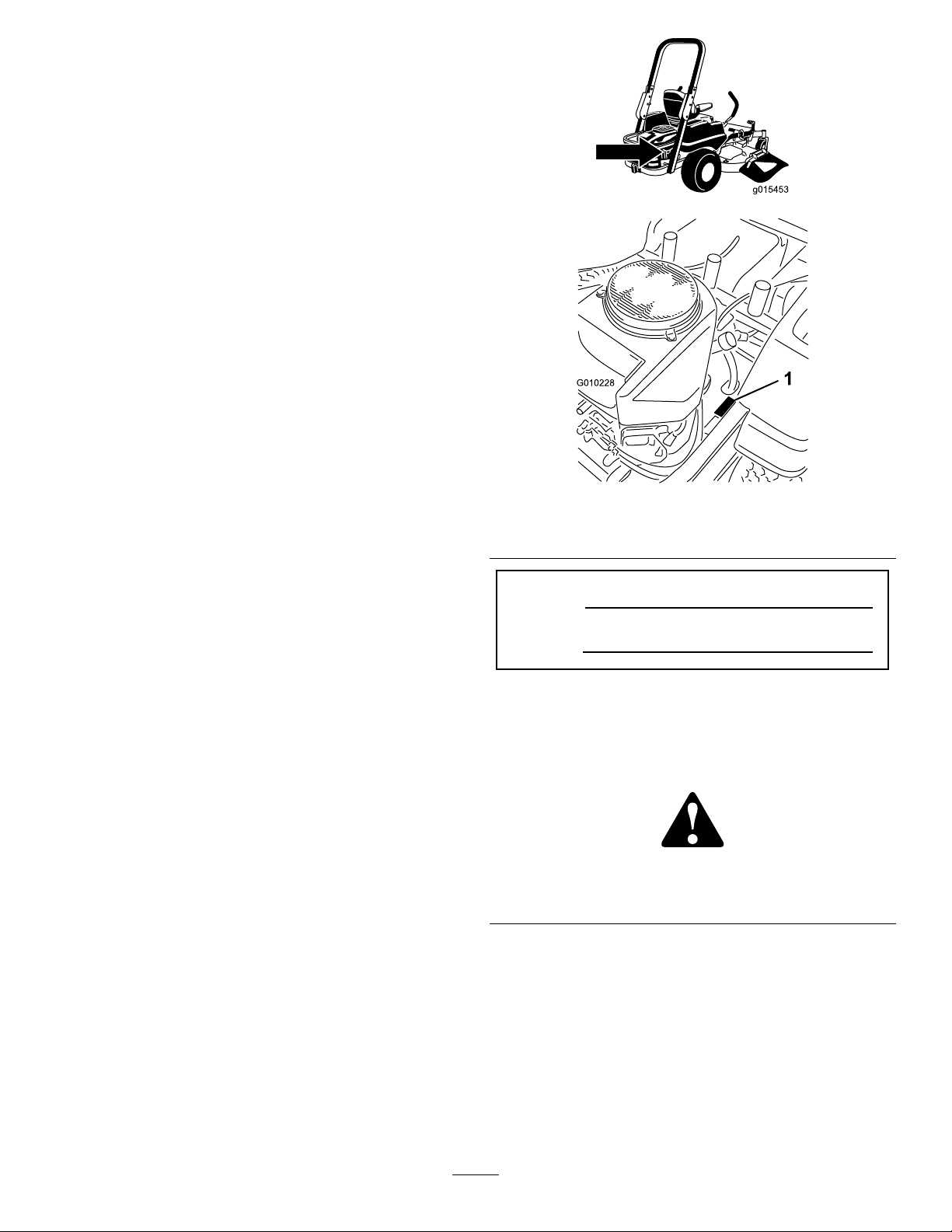
andserialnumbersofyourproductready.Figure1
identiesthelocationofthemodelandserialnumbers
ontheproduct.Writethenumbersinthespace
provided.
g015453
g010228
Figure1
1.Modelandserialnumberlocation
ModelNo.
SerialNo.
Thismanualidentiespotentialhazardsandhas
safetymessagesidentiedbythesafetyalertsymbol
(Figure2),whichsignalsahazardthatmaycause
seriousinjuryordeathifyoudonotfollowthe
recommendedprecautions.
Figure2
1.Safetyalertsymbol
Thismanualuses2otherwordstohighlight
information.Importantcallsattentiontospecial
mechanicalinformationandNoteemphasizesgeneral
informationworthyofspecialattention.
g000502
©2018—TheToro®Company
8111LyndaleAvenueSouth
Bloomington,MN55420
Contactusatwww.Toro.com.
2
PrintedintheUSA.
AllRightsReserved
Page 3

WARNING
Removingstandardoriginalequipmentparts
andaccessoriesmayalterthewarranty ,
traction,andsafetyofthemachine.Failureto
useoriginalToropartscouldcauseserious
injuryordeath.Makingunauthorizedchanges
totheengine,fuelorventingsystem,may
violateEPAandCARBregulations.
Replaceallpartsincluding,butnotlimited
to,tires,belts,blades,andfuelsystem
componentswithoriginalToroparts.
Formodelswithstatedenginehorsepower,thegross
horsepoweroftheenginewaslaboratoryratedbythe
enginemanufacturerinaccordancewithSAEJ1940
andratedtoJ2723.
Donottamperwiththeenginecontrolsoralterthe
governorspeed;doingsomaycreateanunsafe
conditionresultinginpersonalinjury.
3
Page 4

Contents
Safety.......................................................................5
SafeOperationPracticesforRide-On(riding)
RotaryLawnmowerMachines.........................5
SafeOperatingPractices....................................5
ToroRidingMowerSafety...................................6
Model74846.......................................................7
Model74848.......................................................7
SlopeIndicator...................................................9
SafetyandInstructionalDecals........................10
ProductOverview...................................................15
Controls...........................................................16
Operation................................................................17
AddingFuel......................................................17
ThinkSafetyFirst..............................................19
UsingtheRolloverProtectionSystem
(ROPS).........................................................20
TheSafetyInterlockSystem.............................20
CheckingtheEngineOilLevel..........................20
BreakinginaNewMachine..............................21
OperatingtheParkingBrake.............................21
OperatingtheThrottle.......................................21
OperatingtheChoke.........................................21
OperatingtheIgnitionSwitch............................21
StartingandStoppingtheEngine......................22
OperatingtheMowerBladeControlSwitch
(PTO)............................................................23
DrivingForwardorBackward............................23
StoppingtheMachine.......................................25
AdjustingtheHeight-of-Cut...............................25
AdjustingtheAnti-ScalpRollers........................26
PositioningtheSeat..........................................27
AdjustingtheMotionControlLevers..................27
PushingtheMachinebyHand..........................27
Convertingthe48inchMowertoSide
Discharge......................................................28
Convertingthe54inchMowertoSide
Discharge......................................................29
UsingtheSideDischarge.................................31
TransportingtheMachine.................................32
LoadingtheMachine........................................32
OperatingTips.................................................34
Maintenance...........................................................35
RecommendedMaintenanceSchedule(s)...........35
Pre-MaintenanceProcedures..............................37
RaisingtheSeat...............................................37
ReleasingtheMower-DeckCurtain..................37
Lubrication..........................................................37
GreasingtheBearings......................................37
EngineMaintenance...........................................38
ServicingtheAirCleaner..................................38
ServicingtheEngineOil....................................38
ServicingtheSparkPlug...................................41
CleaningtheCoolingSystem............................42
FuelSystemMaintenance...................................42
ReplacingtheFuelFilter...................................42
ElectricalSystemMaintenance...........................43
ServicingtheBattery.........................................43
ServicingtheFuses..........................................44
DriveSystemMaintenance..................................45
CheckingtheTirePressure...............................45
HydraulicSystemMaintenance...........................45
CheckingtheHydraulicOilLevel......................45
ChangingtheHydraulicSystemFilterand
Oil.................................................................45
MowerDeckMaintenance....................................48
ServicingtheCuttingBlades.............................48
MowerDeckLeveling.......................................51
InspectingtheBelts..........................................52
ReplacingtheMowerBelt.................................52
RemovingtheMower........................................53
InstallingtheMowerDeck.................................54
ReplacingtheGrassDeector..........................54
Cleaning..............................................................56
WashingtheUndersideoftheMower................56
WasteDisposal.................................................57
Storage...................................................................57
CleaningandStorage.......................................57
Troubleshooting......................................................59
Schematics.............................................................61
4
Page 5

Safety
◊incorrecthitchingandloaddistribution.
ThefollowinginstructionsarefromtheENstandard
ENISO5395:2013.
SafeOperationPractices forRide-On(riding)Rotary LawnmowerMachines
ThismachinemeetsorexceedsEuropeanStandards
ineffectatthetimeofproduction.However,improper
useormaintenancebytheoperatororownercan
resultininjury .Toreducethepotentialforinjury,
complywiththesesafetyinstructionsandalwayspay
attentiontothesafetyalertsymbol,whichmeans
Caution,Warning,orDanger-“personalsafety
instruction.”Failuretocomplywiththeinstructionmay
resultinpersonalinjuryordeath.
SafeOperatingPractices
Thisproductiscapableofamputatinghandsand
feetandthrowingobjects.Alwaysfollowallsafety
instructionstoavoidseriousinjuryordeath.
Training
•Readtheinstructionscarefully .Befamiliarwiththe
controlsandtheproperuseoftheequipment.
•Neverallowchildrenorpeopleunfamiliarwith
theseinstructionstousethelawnmower.Local
regulationscanrestricttheageoftheoperator.
•Nevermowwhilepeople,especiallychildren,or
petsarenearby.
•Keepinmindthattheoperatororuseris
responsibleforaccidentsorhazardsoccurringto
otherpeopleortheirproperty.
•Donotcarrypassengers.
•Alldriversshouldseekandobtainprofessional
andpracticalinstruction.Suchinstructionshould
emphasize:
–theneedforcareandconcentrationwhen
workingwithride-onmachines;
–controlofaride-onmachineslidingonaslope
willnotberegainedbytheapplicationofthe
brake.Themainreasonsforlossofcontrolare:
◊insufcientwheelgrip;
◊beingdriventoofast;
◊inadequatebraking;
◊thetypeofmachineisunsuitableforits
task;
◊lackofawarenessoftheeffectofground
conditions,especiallyslopes;
Preparation
•Whilemowing,alwayswearsubstantial,
slip-resistantfootwearandlongtrousers.Donot
operatetheequipmentwhenbarefootorwearing
opensandals.
•Thoroughlyinspecttheareawheretheequipment
istobeusedandremoveallobjectswhichmaybe
thrownbythemachine.
•Warning-Fuelishighlyammable.
–Storefuelincontainersspecicallydesigned
forthispurpose.
–Refueloutdoorsonlyanddonotsmokewhile
refueling.
–Addfuelbeforestartingtheengine.Never
removethecapofthefueltankoraddfuel
whiletheengineisrunningorwhentheengine
ishot.
–Iffuelisspilled,donotattempttostartthe
enginebutmovethemachineawayfromthe
areaofspillageandavoidcreatinganysource
ofignitionuntilfuelvaporshavedissipated.
–Replaceallfueltanksandcontainercaps
securely.
•Replacefaultysilencers.
•Beforeusing,alwaysvisuallyinspecttoseethat
theblades,bladeboltsandcutterassemblyare
notwornordamaged.Replacewornordamaged
bladesandboltsinsetstopreservebalance.
•Onmulti-bladedmachines,takecareasrotating
onebladecancauseotherbladestorotate.
Operation
•Bealert,slowdownandusecautionwhenmaking
turns.Lookbehindandtothesidebeforechanging
directions.
•Donotoperatetheengineinaconnedspace
wheredangerouscarbonmonoxidefumescan
collect.
•Mowonlyindaylightoringoodarticiallight.
•Beforeattemptingtostarttheengine,disengage
allbladeattachmentclutchesandshiftintoneutral.
•Donotuseonslopesofmorethan15degrees.
•Rememberthereisnosuchthingasasafeslope.
Travelongrassslopesrequiresparticularcare.T o
guardagainstoverturning:
–donotstoporstartsuddenlywhengoingup
ordownhill;
–uselowspeedsonslopesandduringtight
turns;
–stayalertforhumpsandhollowsandother
hiddenhazards;
5
Page 6

•Usecarewhenpullingloads.
–Useonlyapproveddrawbarhitchpoints.
–Limitloadstothoseyoucansafelycontrol.
–Donotturnsharply.Usecarewhenreversing.
•Watchoutfortrafcwhencrossingornear
roadways.
•Stopthebladesrotatingbeforecrossingsurfaces
otherthangrass.
•Whenusinganyattachments,neverdirect
dischargeofmaterialtowardbystandersnorallow
anyonenearthemachinewhileinoperation.
•Neveroperatethemachinewithdamagedguards
orwithoutsafetyprotectivedevicesinplace.
•Donotchangetheenginegovernorsettingsor
overspeedtheengine.Operatingtheengine
atexcessivespeedcanincreasethehazardof
personalinjury.
•Beforeleavingtheoperator'sposition:
–disengagethepowertake-offandlowerthe
attachments;
–changeintoneutralandsettheparkingbrake;
–stoptheengineandremovethekey .
•Disengagedrivetoattachments,stoptheengine,
anddisconnectthesparkplugwire(s)orremove
theignitionkey.
–beforeclearingblockagesoruncloggingchute;
–beforechecking,cleaningorworkingonthe
lawnmower;
–afterstrikingaforeignobject.Inspectthe
lawnmowerfordamageandmakerepairs
beforerestartingandoperatingtheequipment;
–ifthemachinestartstovibrateabnormally
(checkimmediately).
•Disengagedrivetoattachmentswhentransporting
ornotinuse.
•Stoptheengineanddisengagedriveto
attachment.
–beforerefuelling;
–beforeremovingthegrasscatcher;
–beforemakingheightadjustmentunless
adjustmentcanbemadefromtheoperator's
position.
•Reducethethrottlesettingduringenginerun-out
and,iftheengineisprovidedwithashut-offvalve,
turnthefueloffattheconclusionofmowing.
•Lightningcancausesevereinjuryordeath.If
lightningisseenorthunderisheardinthearea,do
notoperatethemachine;seekshelter.
MaintenanceandStorage
•Keepallnuts,boltsandscrewstighttobesurethe
equipmentisinsafeworkingcondition.
•Neverstoretheequipmentwithfuelinthetank
insideabuildingwherefumescanreachanopen
ameorspark.
•Allowtheenginetocoolbeforestoringinany
enclosure.
•Toreducetherehazard,keeptheengine,
silencer,batterycompartmentandfuelstorage
areafreeofgrass,leaves,orexcessivegrease.
•Checkthegrasscatcherfrequentlyforwearor
deterioration.
•Replacewornordamagedpartsforsafety.
•Ifthefueltankhastobedrained,thisshouldbe
doneoutdoors.
•Whenmachineistobeparked,storedorleft
unattended,lowerthecuttingmeans.
ToroRidingMowerSafety
Thefollowinglistcontainssafetyinformationspecic
toT oroproductsorothersafetyinformationthatyou
mustknowthatisnotincludedintheCENstandard.
•Donotoperatetheengineinaconnedspace
wheredangerouscarbonmonoxideandother
exhaustgassescancollect.
•Keephands,feet,hairandlooseclothingaway
fromattachmentdischargearea,undersideof
mowerandanymovingpartswhileengineis
running.
•Donottouchequipmentorattachmentpartswhich
maybehotfromoperation.Allowtocoolbefore
attemptingtomaintain,adjust,orservice.
•Batteryacidispoisonousandcancauseburns.
Avoidcontactwithskin,eyesandclothing.Protect
yourface,eyes,andclothingwhenworkingwitha
battery.
•Batterygasescanexplode.Keepcigarettes,
sparks,andamesawayfrombattery .
•UseonlygenuineT ororeplacementpartsto
ensurethatoriginalstandardsaremaintained.
•UseonlyToro-approvedattachments.
SlopeOperation
•Donotmowslopesgreaterthan15degrees.
•Donotmowneardrop-offs,ditches,steepbanks,
orwater.Wheelsdroppingoveredgescancause
rollovers,whichmayresultinseriousinjury,death,
ordrowning.
•Donotmowslopeswhengrassiswet.Slippery
conditionsreducetractionandcouldcausesliding
andlossofcontrol.
•Donotmakesuddenturnsorrapidspeedchanges.
•Useawalkbehindmowerand/orahandtrimmer
neardrop-offs,ditches,steepbanks,orwater.
6
Page 7

•Reducespeedanduseextremecautiononslopes.
•Removeormarkobstaclessuchasrocks,tree
limbs,etc.frommowingarea.T allgrasscanhide
obstacles.
•Watchforditches,holes,rocksdips,andrisesthat
changetheoperatingangle,asroughterraincould
overturnthemachine.
•Avoidsuddenstartswhenmowinguphillbecause
themowermaytipbackwards.
SoundPressure
Thisunithasasoundpressurelevelattheoperator’s
earof92dBA,whichincludesanUncertaintyValue
(K)of1dBA.
Soundpowerlevelwasdeterminedaccordingtothe
proceduresoutlinedinENISO5395:2013.
Hand-ArmVibration
•Beawarethatlossoftractionmayoccurgoing
downhill.Weighttransfertothefrontwheels
maycausedrivewheelstoslipandcauselossof
brakingandsteering.
•Alwaysavoidsuddenstartingorstoppingona
slope.Iftireslosetraction,disengagetheblades
andproceedslowlyofftheslope.
•Followthemanufacturer'srecommendations
forwheelweightsorcounterweightstoimprove
stability.
•Useextremecarewithgrasscatchersorother
attachments.Thesecanchangethestabilityofthe
machineandcauselossofcontrol.
UsingtheRolloverProtection System(ROPS)
•Keeptherollbarintheraisedandlockedposition
andusetheseatbeltwhenoperatingthemachine.
•Becertainthattheseatbeltcanbereleased
quicklyintheeventofanemergency.
•Beawarethereisnorolloverprotectionwhenthe
rollbarisdown.
•Checktheareatobemowedandneverfoldthe
ROPSinareaswherethereareslopes,dropoffs
orwater.
Measuredvibrationlevelforlefthand=4.8m/s2
Measuredvibrationlevelforrighthand=4.4m/s2
UncertaintyValue(K)=2.4m/s2
Measuredvaluesweredeterminedaccordingtothe
proceduresoutlinedinENISO5395:2013.
WholeBodyVibration
Measuredvibrationlevel=0.39m/s2
UncertaintyValue(K)=0.19m/s2
Measuredvaluesweredeterminedaccordingtothe
proceduresoutlinedinENISO5395:2013(Riding&
Stand-Ons).
Model74848
SoundPower
Thisunithasaguaranteedsoundpowerlevelof105
dBA,whichincludesanUncertaintyValue(K)of1
dBA.
Soundpowerlevelwasdeterminedaccordingtothe
proceduresoutlinedinISO1 1094.
•Lowertherollbaronlywhenabsolutelynecessary.
Donotweartheseatbeltwiththerollbarfolded
down.
•Checkcarefullyforoverheadclearances(i.e.
branches,doorways,electricalwires)before
drivingunderanyobjectsanddonotcontactthem.
Model74846
SoundPower
Thisunithasaguaranteedsoundpowerlevelof105
dBA,whichincludesanUncertaintyValue(K)of1
dBA.
Soundpowerlevelwasdeterminedaccordingtothe
proceduresoutlinedinISO1 1094.
SoundPressure
Thisunithasasoundpressurelevelattheoperator’s
earof92dBA,whichincludesanUncertaintyValue
(K)of1dBA.
Soundpowerlevelwasdeterminedaccordingtothe
proceduresoutlinedinENISO5395:2013.
Hand-ArmVibration
Measuredvibrationlevelforlefthand=5.8m/s2
Measuredvibrationlevelforrighthand=3.6m/s2
UncertaintyValue(K)=2.3m/s2
Measuredvaluesweredeterminedaccordingtothe
proceduresoutlinedinENISO5395:2013.
7
Page 8

WholeBodyVibration
Measuredvibrationlevel=0.45m/s2
UncertaintyValue(K)=0.22m/s2
Measuredvaluesweredeterminedaccordingtothe
proceduresoutlinedinENISO5395:2013(Riding&
Stand-Ons).
8
Page 9
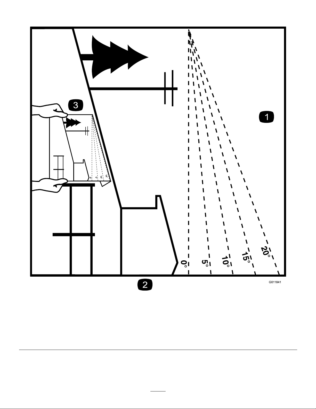
SlopeIndicator
Figure3
Thispagemaybecopiedforpersonaluse.
1.Themaximumslopeyoucansafelyoperatethemachineonis15degrees.Usetheslopecharttodeterminethedegreeofslope
ofhillsbeforeoperating.Donotoperatethismachineonaslopegreaterthan15degrees.Foldalongtheappropriateline
tomatchtherecommendedslope.
2.Alignthisedgewithaverticalsurface,atree,building,fencepole,etc.
3.Exampleofhowtocompareslopewithfoldededge.
9
g011841
Page 10
SafetyandInstructionalDecals
Safetydecalsandinstructionsareeasilyvisibletotheoperatorandarelocatednearanyarea
ofpotentialdanger.Replaceanydecalthatisdamagedorlost.
decaloemmarkt
Manufacturer'sMark
1.Indicatesthebladeisidentiedasapartfromtheoriginal
machinemanufacturer.
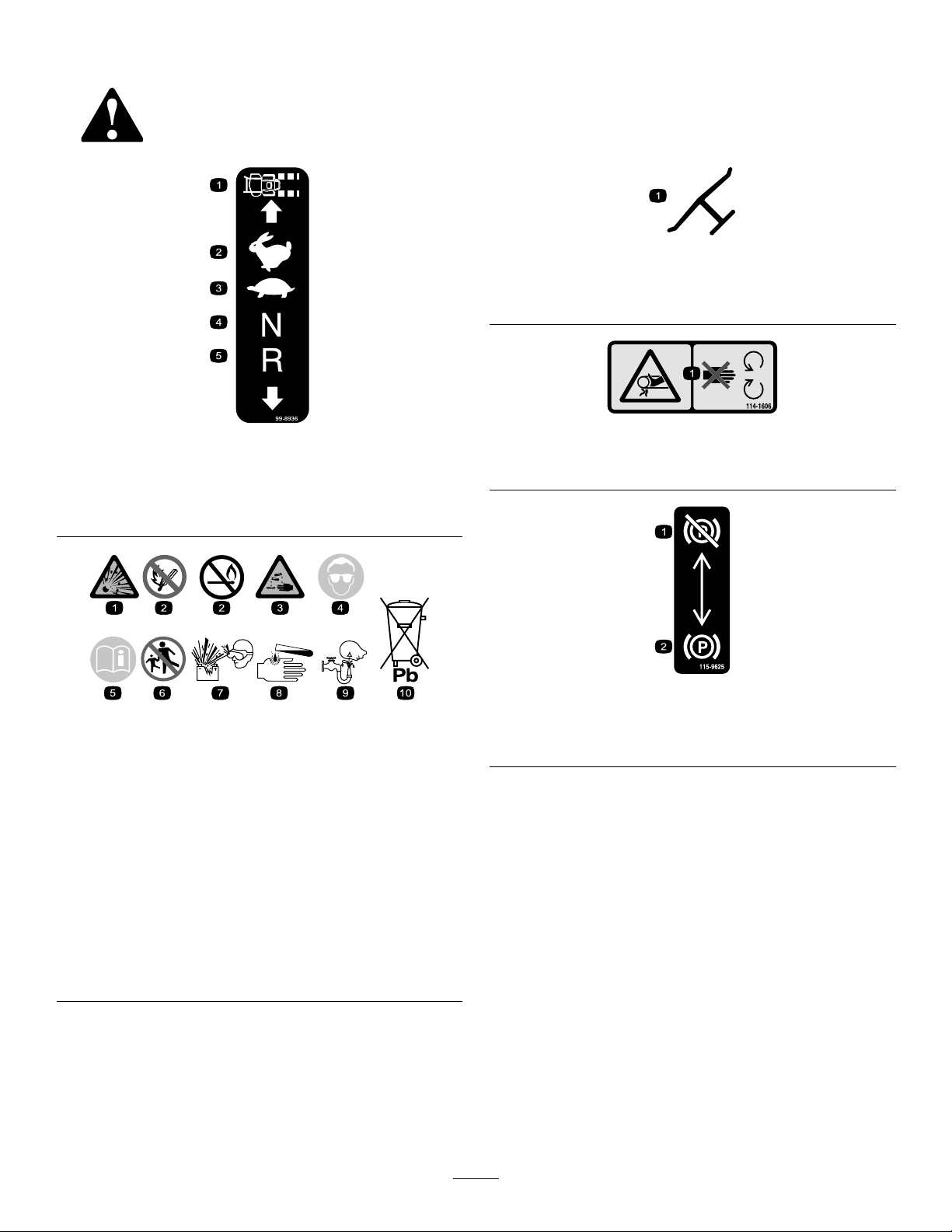
99-8936
1.Machinespeed4.Neutral
2.Fast5.Reverse
3.Slow
BatterySymbols
Someorallofthesesymbolsareonyourbattery
1.Explosionhazard
2.Nore,opename,or
smoking.
3.Causticliquid/chemical
burnhazard
4.Weareyeprotection.9.Flusheyesimmediately
5.ReadtheOperator's
Manual.
6.Keepbystandersasafe
7.Weareyeprotection;
8.Batteryacidcancause
10.Containslead;donot
decal99-8936
decalbatterysymbols
distancefromthebattery.
explosivegasescan
causeblindnessandother
injuries.
blindnessorsevereburns.
withwaterandgetmedical
helpfast.
discard.
114-1606
1.Entanglementhazard,belt—keepallguardsinplace.
115-9625
1.Parking
brake—disengaged
2.Parkingbrake—engaged
decal114-1606
decal115-9625
10
Page 11
decal115-9632
115-9632
1.Powertake-off(PTO),
5.Fast
Bladecontrolswitchon
somemodels
2.Bladecontrolswitch—On6.Continuousvariable
setting
3.Bladecontrolswitch—Off7.Slow
4.Choke
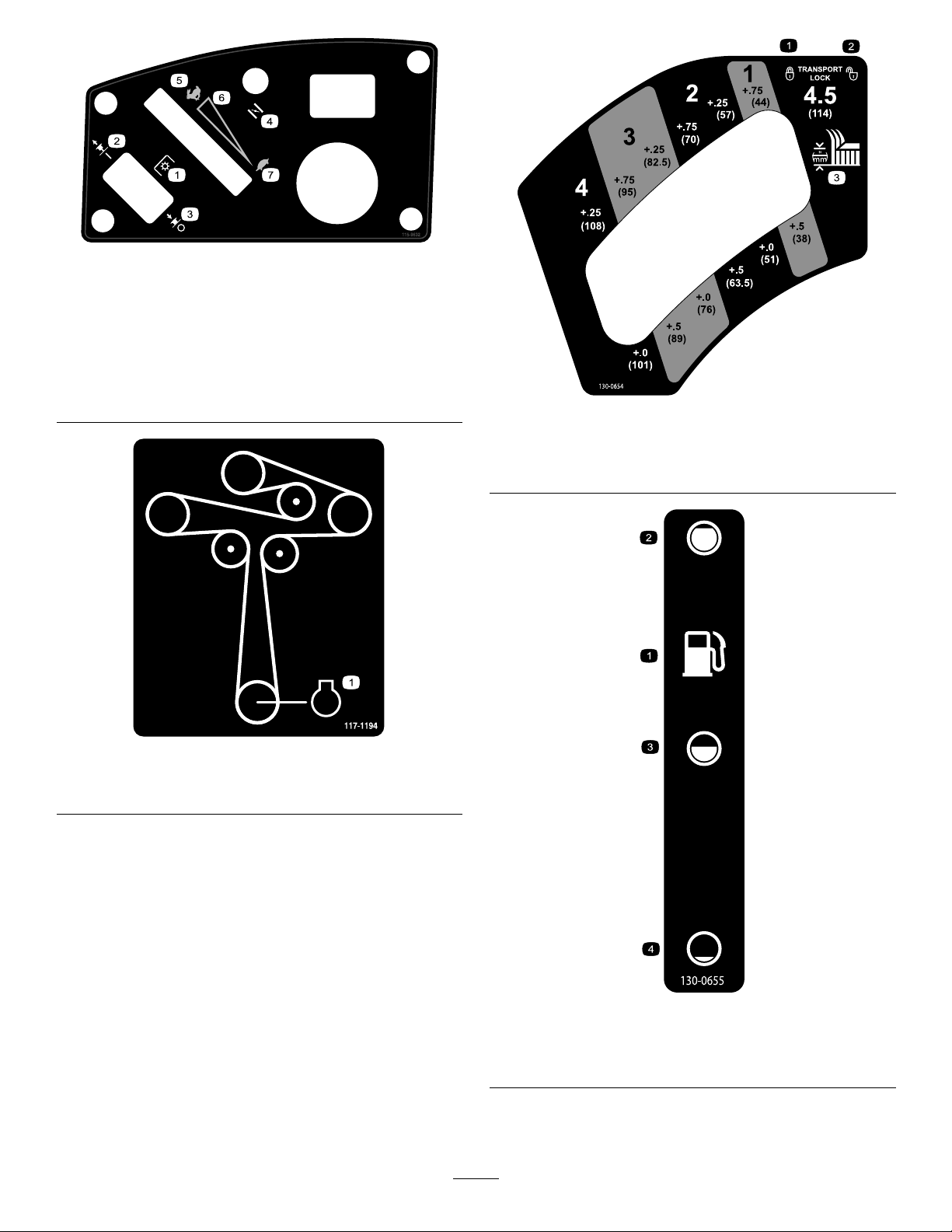
117-1194
decal117-1 194
decal130-0654
130-0654
1.Transport—lock
2.Transport—unlock
3.Height-of-cut
1.Engine
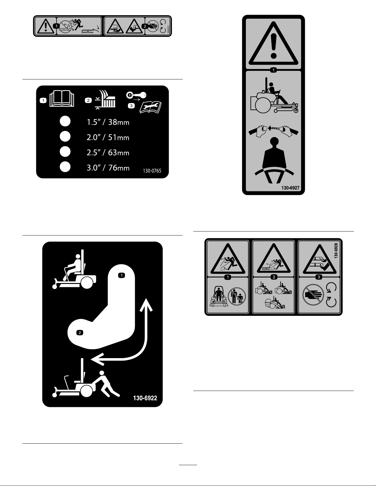
decal130-0655
130-0655
1.Fueltank
2.Full4.Empty
3.Half
11
Page 12
decal130-0731
130-0731
1.Warning—thrownobject
hazard;keepthedeector
shieldinplace.
1.ReadtheOperator's
Manual.
2.Height-of-cutselection
2.Cuttinghazardofhandor
foot,mowerblade—keep
awayfrommovingparts.
130-0765
3.Removethekeyfrom
theignitionandreadthe
Operator'sManualbefore
permorningmaintenance.
decal130-0765
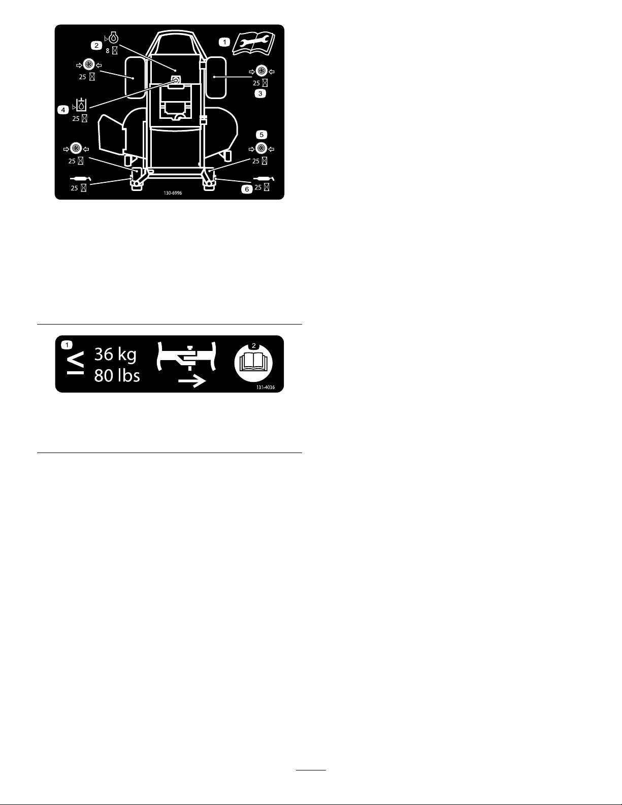
decal130-6927
130-6927
1.Warning—alwaysusetheROPSandweartheseatbelt
whenseatedintheoperator'sposition.
1.Bypassleverpositionfor
operatingthemachine.
130-6922
2.Bypassleverpositionfor
pushingthemachine.
decal130-6928
130-6928
1.Thrownobject
hazard—keepbystanders
awayfromthemachine.
2.Thrownobjecthazard,
mower—donotoperate
thewithoutdeector,
dischargecover,orgrass
collectionsysteminplace.
decal130-6922
3.Cutting/dismembermentof
handorfoot—stayaway
frommovingparts.
12
Page 13
decal130-6996
130-6996
1.ReadtheOperator's
Manualforinformationon
maintenance.
2.Checktheengineoilevery
8hours
3.Checkthedrivewheeltire
pressureevery25hours
1.Themaximumdrawbar
pullis36kg(80lb).
4.Checkthehydraulicoil
every25hours
5.Checkthecasterwheel
tirepressureevery25
hours
6.Lubricatethecasterwheel
every25hours
decal131-4036
131-4036
2.ReadtheOperator's
Manual.
13
Page 14
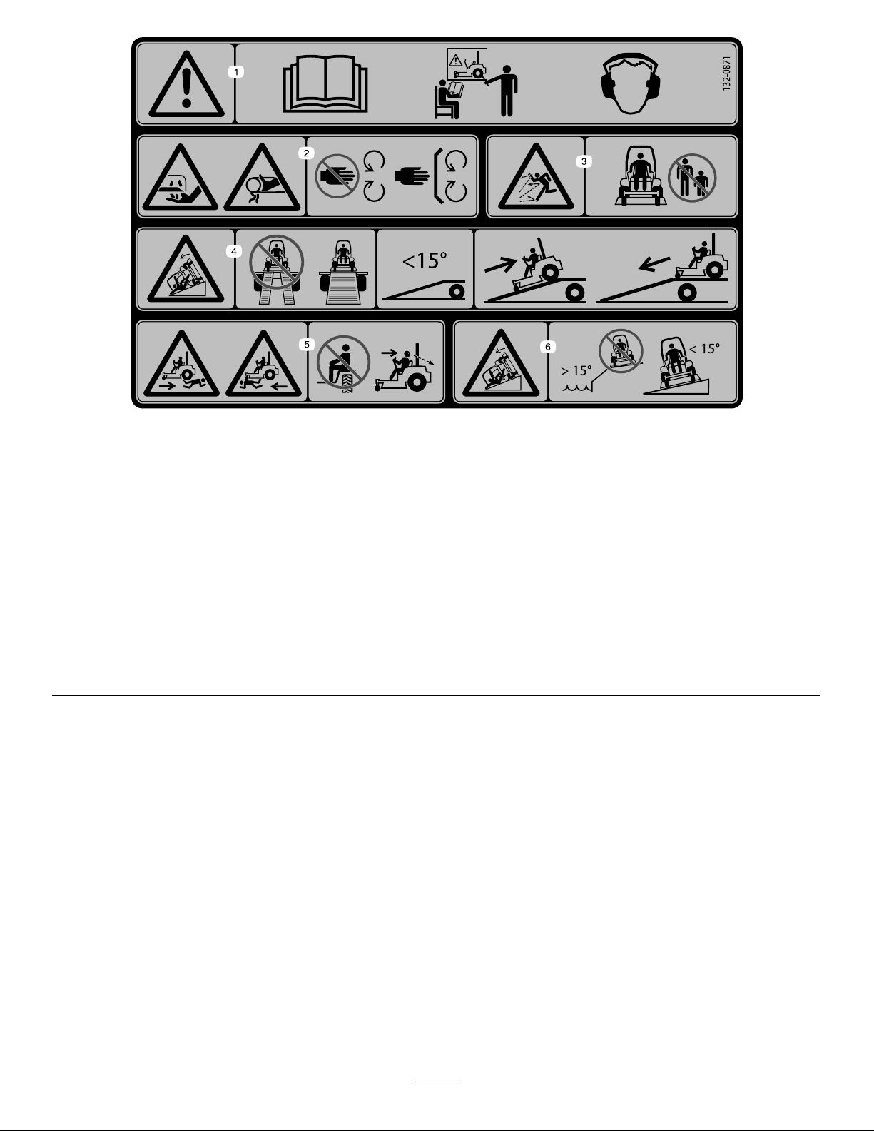
132-0871
Note:Thismachinecomplieswiththeindustrystandardstabilitytestinthestaticlateralandlongitudinaltestswiththemaximum
recommendedslopeindicatedonthedecal.ReviewtheinstructionsforoperatingthemachineonslopesintheOperator’sManualas
wellastheconditionsinwhichyouwouldoperatethemachinetodeterminewhetheryoucanoperatethemachineinthoseconditions
onthatdayandatthatsite.Changesintheterraincanresultinachangeinslopeoperationforthemachine.Ifpossible,keepthe
cuttingunitsloweredtothegroundwhileoperatingthemachineonslopes.Raisingthecuttingunitswhileoperatingonslopescan
causethemachinetobecomeunstable.
decal132-0871
1.Warning—readtheOperator’sManual;donotoperatethis
machineunlessyouaretrained;wearhearingprotection.
2.Cutting,dismembering,andentanglementhazard—keep
handsawayfrommovingparts;keepallguardsandshieldsin
place.
3.Thrownobjecthazard—keepbystandersaway .6.Tippinghazardonslopes—donotuseonslopesnearopen
4.Ramphazard—whenloadingontoatrailer,donotusedual
ramps;onlyuseasingularrampwideenoughforthemachine
andthathasaninclinelessthan15°;backuptheramp(in
reverse)anddriveforwardofftheramp.
5.Bodilyharmhazard—donotcarrypassengers;lookbehind
youwhenmowinginreverse.
water;donotuseonslopesgreaterthan15°.
14
Page 15
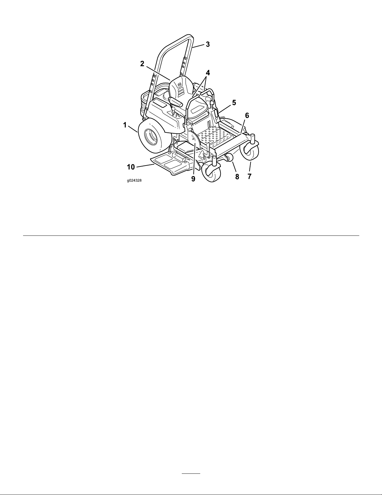
ProductOverview
g024328
Figure4
1.Drivewheel4.Motioncontrollevers7.Frontcasterwheel
2.Operatorseat
3.Rolloverprotectionsystem
(ROPS)
5.Parkingbrake8.Anti-scalproller
6.Footrest
9.Footpedaldeckliftand
height-of-cut
10.Deector
15
Page 16
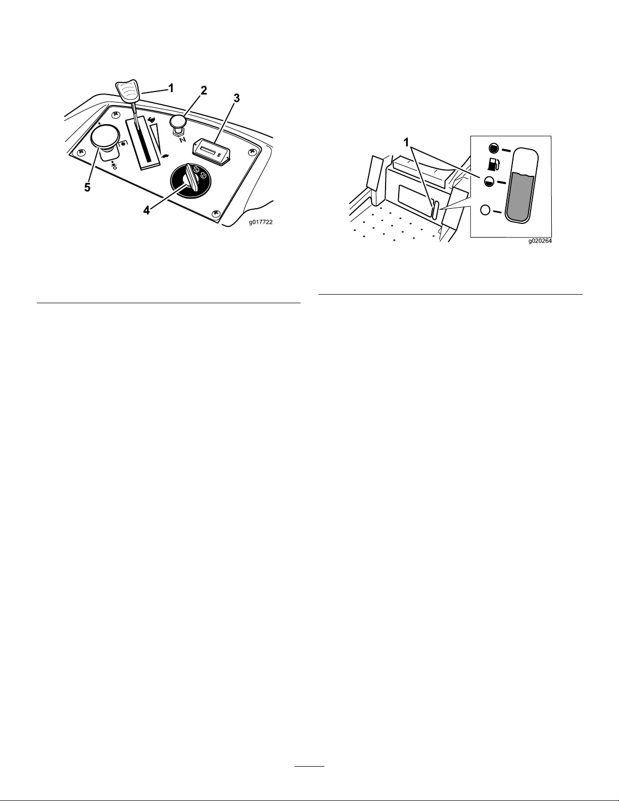
Controls
Becomefamiliarwithallthecontrolsbeforeyoustart
theengineandoperatethemachine(Figure5).
Figure5
1.Throttlecontrol4.Ignitionswitch
2.Choke5.Bladecontrolswitch(PTO)
3.Hourmeter
controlswitch(PTO)isengaged.Usethesetimesfor
schedulingregularmaintenance(Figure5).
FuelGauge
Thefuelwindowlocatedbelowtheoperatorposition
canbeusedtoverifythelevelofgasolineinthetank
(Figure6).
g017722
g020264
Figure6
1.Fuelgaugewindow
IgnitionSwitch
Theignitionswitchhasthreepositions:Start,Run
andOff.ThekeywillturntoStartandmovebackto
Runuponrelease.TurningthekeytotheOffposition
willstoptheengine;however,alwaysremovethekey
whenleavingthemachinetopreventtheenginefrom
accidentallystarting(Figure5).
ThrottleControl
ThethrottlecontrolisvariablebetweenFastand
Slow.Movingthrottleleverforwardwillincrease
enginespeedandmovingthrottlelevertotherearwill
decreaseenginespeed.Movingthethrottleforward
intothedetentisfullthrottle(Figure5).
Choke
Usethechoketostartacoldengine.Pullthechoke
knobuptoengageit.Pushdownonthechokeknob
todisengageit.
Blade-ControlSwitch(Power
Take-Off)
Thebladecontrolswitch,representedbyapower
take-off(PTO)symbol,engagesanddisengages
powertothemowerblades(Figure5).
MotionControlLevers
Themotioncontrolleversarespeedsensitivecontrols
ofindependentwheelmotors.Movingaleverforward
orbackwardturnsthewheelonthesamesideforward
orinreverse;wheelspeedisproportionaltothe
amounttheleverismoved.Movethecontrollevers
outwardfromthecentertotheneutrallockposition
andexitthemachine(Figure4).Alwayspositionthe
motioncontrolleversintotheneutrallockposition
whenyoustopthemachineorleaveitunattended.
ParkingBrakeLever
Locatedonleftsideoftheconsole(Figure4).The
brakeleverengagesaparkingbrakeonthedrive
wheels.Pulltheleverupandrearwardtoengagethe
brake.Pushtheleverforwardanddowntodisengage
thebrake.
FootPedalDeckLiftSystem
Thefootpedaldeckliftsystemallowstheoperator
tolowerandraisethedeckfromtheseatedposition.
Theoperatorcanusethefootpedaltoliftthedeck
brieytoavoidobstaclesorlockthedeckinthe
highestheight-of-cutortransportposition(Figure4).
Height-of-CutLever
HourMeter
Thehourmeterrecordsthenumberofhoursthe
bladeshaveoperated.Itoperateswhentheblade
Theheight-of-cutleverworkswiththefootpedalto
lockthedeckinaspeciccuttingheight.Onlyadjust
theheightofcutwhilemachineisnotmoving(Figure
4).
16
Page 17

Attachments/Accessories
AselectionofT oroapprovedattachmentsand
accessoriesisavailableforusewiththemachineto
enhanceandexpanditscapabilities.Contactyour
AuthorizedServiceDealerorDistributororgoto
www.T oro.comforalistofallapprovedattachments
andaccessories.
Operation
Note:Determinetheleftandrightsidesofthe
machinefromthenormaloperatingposition.
AddingFuel
•Forbestresults,useonlyclean,fresh,unleaded
gasolinewithanoctaneratingof87orhigher
((R+M)/2ratingmethod).
•Oxygenatedfuelwithupto10%ethanolor15%
MTBEbyvolumeisacceptable.
•DoNotuseethanolblendsofgasoline(such
asE15orE85)withmorethan10%ethanolby
volume.Performanceproblemsand/orengine
damagemayresultwhichmaynotbecovered
underwarranty.
•DoNotusegasolinecontainingmethanol.
•DoNotstorefueleitherinthefueltankorfuel
containersoverthewinterunlessafuelstabilizer
isused.
•DoNotaddoiltogasoline.
DANGER
Incertainconditionsduringfueling,static
electricitycanbereleasedcausingaspark
whichcanignitethegasolinevapors.Are
orexplosionfromgasolinecanburnyouand
othersandcandamageproperty.
•Alwaysplacegasolinecontainersonthe
groundawayfromyourvehiclebefore
lling.
•Donotllgasolinecontainersinsidea
vehicleoronatruckortrailerbedbecause
interiorcarpetsorplastictruckbedliners
mayinsulatethecontainerandslowthe
lossofanystaticcharge.
•Whenpractical,removegas-powered
equipmentfromthetruckortrailerand
refueltheequipmentwithitswheelsonthe
ground.
•Ifthisisnotpossible,thenrefuelsuch
equipmentonatruckortrailerfroma
portablecontainer,ratherthanfroma
gasolinedispensernozzle.
•Ifagasolinedispensernozzlemustbe
used,keepthenozzleincontactwiththe
rimofthefueltankorcontaineropeningat
alltimesuntilfuelingiscomplete.
17
Page 18
WARNING
Gasolineisharmfulorfatalifswallowed.
Long-termexposuretovaporscancause
seriousinjuryandillness.
•Avoidprolongedbreathingofvapors.
•Keepfaceawayfromnozzleandgastank
orconditioneropening.
•Keepgasawayfromeyesandskin.
DANGER
Incertainconditions,gasolineisextremely
ammableandhighlyexplosive.Areor
explosionfromgasolinecanburnyouand
othersandcandamageproperty.
•Fillthefueltankoutdoors,inanopenarea,
whentheengineiscold.Wipeupany
gasolinethatspills.
•Neverllthefueltankinsideanenclosed
trailer.
Addthecorrectamountofgasstabilizer/conditioner
tothegas.
Note:Afuelstabilizer/conditionerismosteffective
whenmixedwithfreshgasoline.T ominimizethe
chanceofvarnishdepositsinthefuelsystem,usefuel
stabilizeratalltimes.
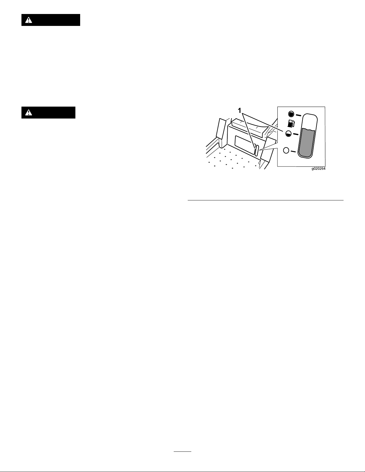
FuelGauge
Usethefuelwindowbelowtheoperatortoverifythe
levelofgasolinebeforellingthetank(Figure7).
g020264
Figure7
1.Fuelgaugewindow
•Donotllthefueltankcompletelyfull.Add
gasolinetothefueltankuntilthelevelis6
to13mm(1/4to1/2inch)belowthebottom
ofthellerneck.Thisemptyspaceinthe
tankallowsgasolinetoexpand.
•Neversmokewhenhandlinggasoline,and
stayawayfromanopenameorwhere
gasolinefumesmaybeignitedbyaspark.
•Storegasolineinanapprovedcontainer
andkeepitoutofthereachofchildren.
Neverbuymorethana30-daysupplyof
gasoline.
•Donotoperatewithoutentireexhaust
systeminplaceandinproperworking
condition.
UsingStabilizer/Conditioner
Useafuelstabilizer/conditionerinthemachineto
providethefollowingbenets:
•Keepsgasolinefreshduringstorageof90daysor
less.Forlongerstorageitisrecommendedthat
thefueltankbedrained.
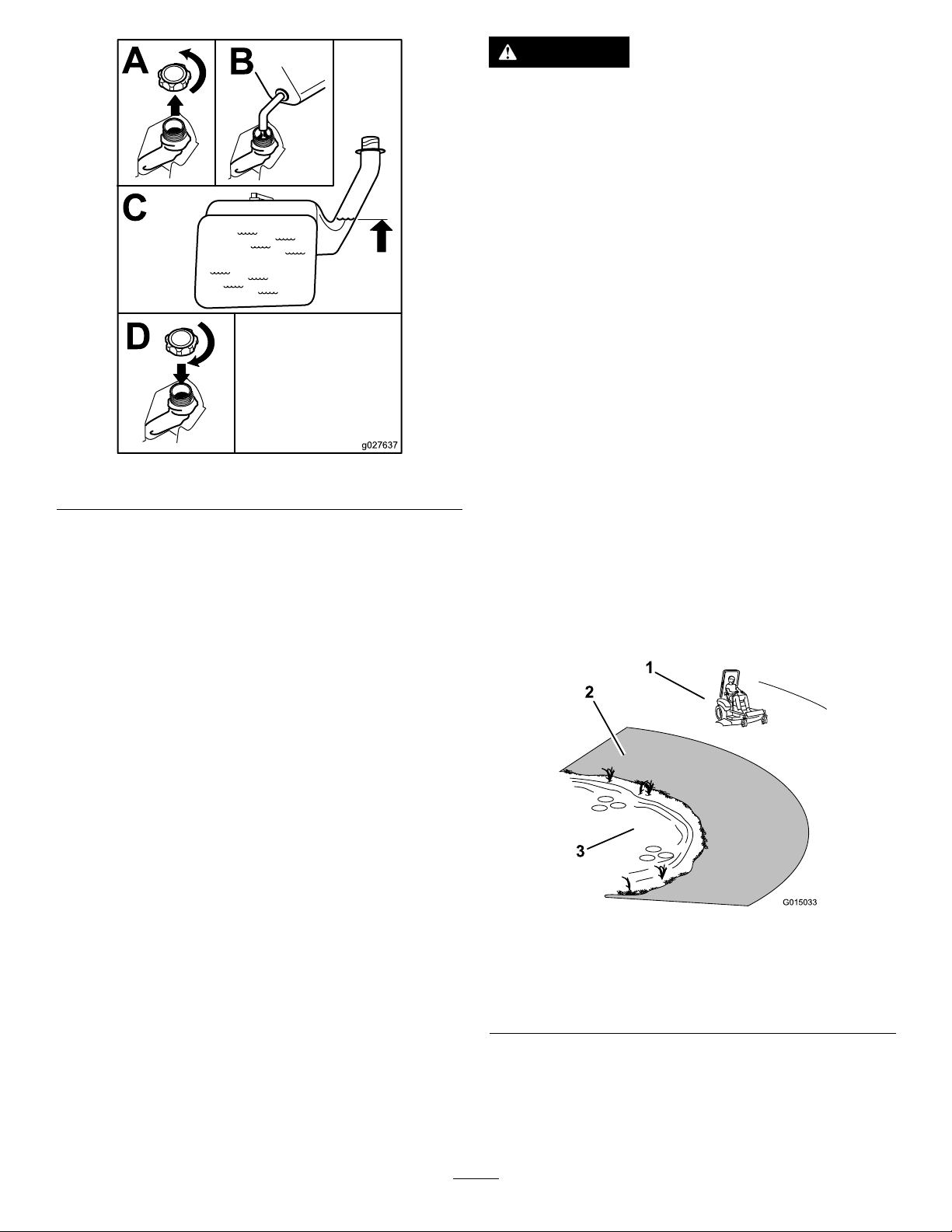
FillingtheFuelTank
Makesuretheengineisshutoffandthemotion
controlsareintheparkposition.
Important:DoNotoverllfueltank.Fillthe
fueltanktothebottomofthellerneck.The
emptyspaceinthetankallowsthefueltoexpand.
Overllingmayresultinfuelleakageordamageto
theengineoremissionsystem.
1.Cleanaroundthefueltankcapandremovethe
cap.
Note:Y oucanusethefuelwindowbelow
theoperatingpositionverifythepresenceof
gasolinebeforellingthetank(Figure7).
2.Slowlyaddregular,unleadedgasolineuntilthe
fuelreachesthebaseofthellerneckFigure8.
•Cleanstheenginewhileitruns
•Eliminatesgum-likevarnishbuildupinthefuel
system,whichcauseshardstarting
Important:Donotusefueladditivescontaining
methanolorethanol.
18
Page 19
DANGER
Mowingonwetgrassorsteepslopescan
causeslidingandlossofcontrol.
Wheelsdroppingoveredgescancause
rollovers,whichmayresultinseriousinjury,
deathordrowning.
Alossoftractionisalossofsteeringcontrol.
Toavoidlossofcontrolandpossibilityof
rollover:
•Donotmowneardrop-offsornearwater.
•Donotmowslopesgreaterthan15degrees.
•Reducespeedanduseextremecautionon
slopes.
•Whenmowingslopes,graduallyworkfrom
lowertohigherareasontheincline.
Figure8
3.Installthefueltankcapsecurelyandtighten
untilit“clicks”.Wipeupanygasolinethatmay
havespilled.
ThinkSafetyFirst
Pleasecarefullyreadallofthesafetyinstructionsand
decalsinthesafetysection.Knowingthisinformation
couldhelpyou,yourfamily,petsorbystandersavoid
injury.
g027637
•Avoidsuddenturnsorrapidspeed
changes.
•Turnup,intoaninclinewhenchanging
directionsonslopes.T urningdownthe
slopereducestraction.
•Attachmentschangethehandling
characteristicsofthemachine.Useextra
cautionwhenusingattachmentswiththe
machine.
Figure9
1.SafeZone-usethemachinehere
2.Usewalkbehindmowerand/orhandtrimmerneardrop-offs
andwater .
3.Water
19
g015033
Page 20
CAUTION
Thismachineproducessoundlevelsin
excessof85dBAattheoperatorsearandcan
causehearinglossthroughextendedperiods
ofexposure.
Wearhearingprotectionwhenoperatingthis
machine.
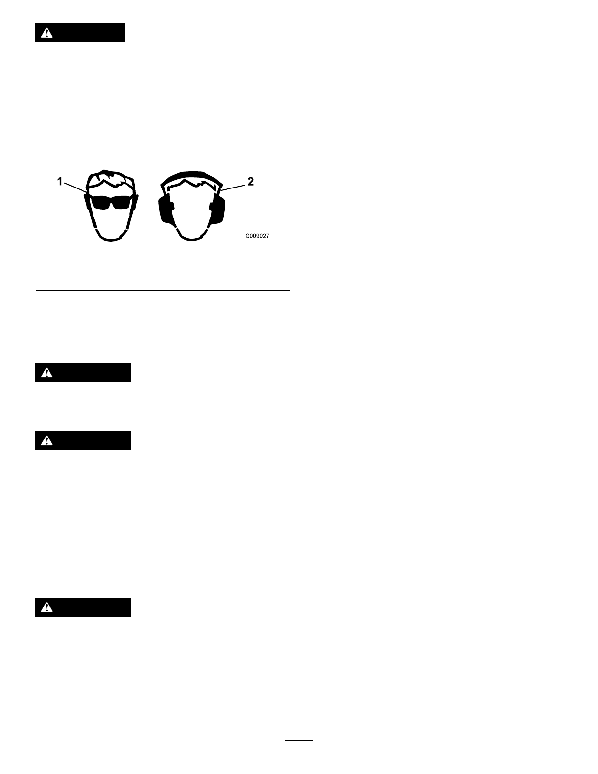
Theuseofprotectiveequipmentforeyes,ears,
hands,feet,andheadisrecommended.
Figure10
1.Wearsafetyglasses
2.Wearhearingprotection
UnderstandingtheSafetyInterlock System
Thesafetyinterlocksystemisdesignedtopreventthe
enginefromstartingunless:
•Theparkingbrakeisengaged.
•Thebladesaredisengaged.
•Themotioncontrolleversareintheneutrallock
position.
Thesafetyinterlocksystemalsoisdesignedtostop
theenginewhenthecontrolleversareoutofthe
neutrallockpositionwiththeparkingbrakeonorif
yourisefromtheseatwhenthebladesareengaged.
TestingtheSafetyInterlock
g009027
System
Testthesafetyinterlocksystembeforeyouusethe
machineeachtime.Ifthesafetysystemdoesnot
operateasdescribedbelow,haveanAuthorized
ServiceDealerrepairthesafetysystemimmediately .
UsingtheRollover ProtectionSystem(ROPS)
WARNING
Toavoidinjuryordeathfromrollover:keep
therollbarinstalledandusetheseatbelt.
WARNING
Thereisnorolloverprotectionwhentheroll
barisremoved.
•Driveslowlyandcarefully.
•Checkcarefullyforoverheadclearances
(i.e.branches,doorways,electricalwires)
beforedrivingunderanyobjectsanddo
notcontactthem.
TheSafetyInterlockSystem
1.Whilesittingontheseat,engagetheparking
brakeandmovethebladecontrolswitchtoOn.
Trystartingtheengine;theengineshouldnot
crank.
2.Whilesittingontheseat,engagetheparking
brakeandmovethebladecontrolswitchtoOff.
Moveeithermotioncontrollever(forwardor
reverse).Trystartingtheengine;theengine
shouldnotcrank.Repeatwiththeothermotion
controllever.
3.Whilesittingontheseat,engagetheparking
brake,movethebladecontrolswitchtoOff,
andlockthemotioncontrolleversinneutral.
Starttheengine.Whiletheengineisrunning,
releasetheparkingbrake,engagetheblade
controlswitch,andriseslightlyfromtheseat;
theengineshouldstop.
4.Whilesittingontheseat,engagetheparking
brake,movethebladecontrolswitchtoOff,and
lockthemotioncontrolleversinneutral.Start
theengine.Whiletheengineisrunning,center
themotioncontrols;theengineshouldstop.
WARNING
Ifsafetyinterlockswitchesaredisconnected
ordamagedthemachinecouldoperate
unexpectedlycausingpersonalinjury.
•Donottamperwiththeinterlockswitches.
•Checktheoperationoftheinterlock
switchesdailyandreplaceanydamaged
switchesbeforeoperatingthemachine.
CheckingtheEngineOil Level
Beforeyoustarttheengineandusethemachine,
checktheoillevelintheenginecrankcase;referto
CheckingtheEngineOilLevel(page38).
20
Page 21

BreakinginaNewMachine
Newenginestaketimetodevelopfullpower.Mower
decksanddrivesystemshavehigherfrictionwhen
new,placingadditionalloadontheengine.Allow
40to50hoursofbreak-intimefornewmachinesto
developfullpowerandbestperformance.
OperatingtheParking Brake
g008946
Figure13
Alwayssettheparkingbrakewhenyoustopthe
machineorleaveitunattended.
SettingtheParkingBrake
Figure11
ReleasingtheParkingBrake
OperatingtheChoke
Usethechoketostartacoldengine.
1.Iftheengineiscold,usethechoketostartthe
engine.
2.Pulluponthechokeknobtoengagethechoke
beforeusingtheignitionswitch(Figure14).
3.Pushdownonthechoketodisengagethechoke
aftertheenginehasstarted(Figure14).
g027638
Figure12
OperatingtheThrottle
ThethrottlecontrolcanbemovedbetweenFastand
Slowpositions(Figure13).
Alwaysusethefastpositionwhenturningonthe
mowerdeckwiththebladecontrolswitch(PTO).
g027639
1.On2.Off
Figure14
g008959
OperatingtheIgnition Switch
1.TurntheignitionkeytotheStartposition(Figure
15).Whentheenginesstarts,releasethekey.
Note:Additionalstartingcyclesmaybe
requiredwhenstartingtheenginefortherst
timeafterthefuelsystemhasbeenwithoutfuel
completely.
21
Page 22
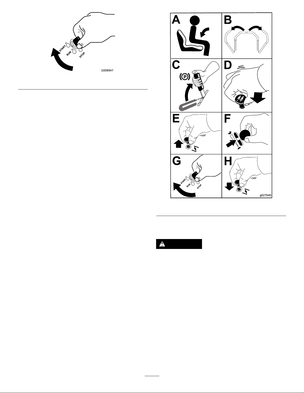
Figure15
2.Turntheignitionkeytostoptostoptheengine.
StartingandStoppingthe Engine
StartingtheEngine
Note:Awarmorhotenginemaynotrequirechoking
(Figure16).
Important:Donotengagestarterformorethan5
secondsatatime.Iftheenginefailstostartallow
a15secondcool-downperiodbetweenattempts.
Failuretofollowtheseinstructionscanburnout
thestartermotor.
Note:Ifthefuelsystemwasdepletedoffuel—add
fueltothemachineanduseadditionalstartingcycles
whenstartingtheengine.
g008947
g027640
Figure16
StoppingtheEngine
CAUTION
Injurycanoccurifchildrenorbystanders
moveorattempttooperatethemachinewhile
itisunattended.
Alwaysremovetheignitionkeyandsetthe
parkingbrakewhenleavingthemachine
unattended,evenifjustforafewminutes.
22
Page 23

OperatingtheMowerBlade ControlSwitch(PTO)
Thebladecontrolswitch(PTO)startsandstopsthe
mowerbladesandanypoweredattachments.
EngagingtheBladeControl Switch(PTO)
Engagethebladecontrolswitch(PTO)withthe
throttlepositionatFast.
Note:Engagingthebladecontrolswitch(PTO)with
thethrottlepositionathalforlesswillcauseexcessive
weartothedrivebelts.
Figure17
g008945
Figure18
g027641
DisengagingtheBladeControl Switch(PTO)
g009174
Figure19
DrivingForwardor Backward
Thethrottlecontrolregulatestheenginespeedas
measuredinrpm(revolutionsperminute).Place
thethrottlecontrolinthefastpositionforbest
23
Page 24

performance.Alwaysoperateinthefullthrottle
positionwhenmowing.
CAUTION
Machinecanspinveryrapidly.Operatormay
losecontrolofmachineandcausepersonal
injuryordamagetomachine.
•Usecautionwhenmakingturns.
•Slowthemachinedownbeforemaking
sharpturns.
UsingtheMotionControlLevers
g008952
Figure21
Figure20
1.Motioncontrol
lever-neutrallockposition
2.Center,unlockedposition5.Frontofmachine
3.Forward
4.Backward
DrivingForward
Note:Theenginewillkillifthetractioncontrollevers
aremovedwiththeparkingbrakeengaged.
DrivingBackward
Note:Alwaysusecautionwhenbackingupand
turning.
1.Movetheleverstothecenter,unlockedposition.
2.Togobackward,slowlypullthemotioncontrol
leversrearward(Figure22).
g004532
1.Releasetheparkingbrake;refertoReleasing
theParkingBrakeinOperation.
2.Movetheleverstothecenter,unlockedposition.
3.Togoforward,slowlypushthemotioncontrol
leversforward(Figure21).
g008953
Figure22
24
Page 25

StoppingtheMachine
UsingtheFootPedalDeckLift System
WARNING
Childrenorbystandersmaybeinjuredifthey
moveorattempttooperatethemachinewhile
itisunattended.
Alwaysremovetheignitionkeyandmove
themotioncontrolleversoutwardtothe
parkpositionwhenleavingthemachine
unattended,evenifjustforafewminutes.
Tostopthemachine,movethetractioncontrollevers
toneutralandmovetolockedposition,disengagethe
bladecontrolswitch(PTO),andturntheignitionkey
tooff.
Settheparkingbrakewhenyouleavethemachine;
refertoSettingtheParkingBrake.Rememberto
removethekeyfromtheignitionswitch.
AdjustingtheHeight-of-Cut
Themachineisequippedwithafootpedaldecklift
system.Theoperatorcanusethefootpedaltolift
thedeckbrieytoavoidobstaclesorlockthedeckin
thehighestheight-of-cutortransportposition.The
operatorcanusetheheightofcutleverwiththefoot
pedaltolockthedeckinaspeciccuttingheight.
•Pressthepedaldowntoraisethedeck;continue
topressthepedaluntilthedeckislockedinthe
transportposition(Figure23).
•Pushonthedeckliftpedalwithyourfootandpull
thetransportlockhandlerearwardtodisengage
thetransportlock(Figure23).
g024409
Figure23
TransportLockPosition
AdjustingtheHeight-of-Cut
Theheight-of-cutcanbeadjustedfrom38to114mm
(1-1/2to4-1/2inch)in6mm(1/4inch)increments
byrelocatingtheheight-of-cutpinintodifferenthole
locations.
1.Pushonthedeckliftpedalwithyourfootand
raisethemowerdecktothetransportlock
position(alsothe114mm(4-1/2inch)cutting
heightposition)(Figure24).
2.Toadjust,removethepinfromtheheight-of-cut
bracket(Figure24).
3.Selectaholeintheheight-of-cutsystem
correspondingtotheheight-of-cutdesiredand
insertthepin(Figure24).
4.Pushonthedeckliftpedalwithyourfootandpull
thehandlerearwardtodisengagethetransport
lock(Figure23).
5.Lowerthedeckslowlyuntilthelevermakes
contactwiththepin.
25
Page 26

Figure24
1.Deckliftpedal3.Height-of-cutpositions
2.Handle4.Pin
AdjustingtheAnti-Scalp Rollers
Wheneveryouchangetheheight-of-cut,itis
recommendedtoadjusttheheightoftheanti-scalp
rollers.
1.Disengagethebladecontrolswitch(PTO),move
themotioncontrolleverstotheneutrallock
positionandsettheparkingbrake.
2.Stoptheengine,removethekey ,andwait
forallmovingpartstostopbeforeleavingthe
operatingposition.
3.Removetheangenut,anti-scalprollerandbolt
fromthebracket(Figure25).
g024410
Note:Keeptheboltandanti-scalproller
togetherwhenremoving.
Figure25
1.FlangeNut4.Bushing
2.Spacer
3.Anti-scalproller
5.Bolt
4.Aligntheboltandanti-scalprollerintheholeof
thebracketthatmatchedtheclosestheightof
cutposition(Figure25).
5.Inserttheboltintothebracketholeandsecure
theboltandanti-scalprollerwiththeangenut
(Figure25).
g024312
26
Page 27

PositioningtheSeat
Theseatcanmoveforwardandbackward.Position
theseatwhereyouhavethebestcontrolofthe
machineandaremostcomfortable.
Figure26
AdjustingtheMotion
1.Loosentheupperboltholdingthecontrollever
tothecontrolarmshaft.
2.Loosenthelowerboltjustenoughtopivotthe
controlleverforeoraft.Tightenbothboltsto
securethecontrolinthenewposition.
3.Repeattheadjustmentfortheoppositecontrol
lever.
PushingtheMachineby Hand
Important:Alwayspushthemachinebyhand.
Nevertowthemachinebecausedamagemay
occur.
ToPushtheMachine
1.Parkthemachineonalevelsurfaceand
g027632
disengagethebladecontrolswitch.
2.Movethemotioncontrolleversoutwardto
neutrallockposition,stoptheengine,remove
thekey,andwaitforallmovingpartstostop
beforeleavingtheoperatingposition.Makesure
theparkingbrakeisdisengaged.
ControlLevers
AdjustingtheHeight
Note:Repeattheadjustmentfortheoppositecontrol
lever.
Themotioncontrolleverscanbeadjustedhigheror
lowerformaximumoperatorcomfort(Figure27).
Figure27
3.Dothisprocedureoneachsideofthe
machineFigure28.
g027642
g027252
Figure28
AdjustingtheTilt
Themotioncontrolleverscanbetiltedforeoraftfor
maximumoperatorcomfort.
ToOperatetheMachine
Movethebypasstothepositionforoperatingthe
machine(Figure28)toengagethewheelmotors.
27
Page 28

Convertingthe48inch MowertoSideDischarge
Themowerdeckandmowerbladesshippedwiththis
machineweredesignedforoptimummulchingand
sidedischargeperformance.
Installthefastenersintothesameholesinthedeck
theywereoriginallyremovedfrom.Thisensureno
holesareleftopenwhenthedeckisoperated.
DANGER
Openholesinthemowerexposeyouand
otherstothrowndebris.Debristhrownoutof
holesinthemowercancauseinjury.
•Neveroperatethemowerwithouthardware
mountedinallholesinthemower.
•Installhardwareinmountingholeswhen
thebafeisremoved.
RemovingtheMulchBafe
1.Parkthemachineonalevelsurfaceand
disengagethebladecontrolswitch.
2.Movethemotioncontrolleversoutwardtothe
neutrallockposition,settheparkingbrake,
stoptheengine,removethekey ,andwaitfor
allmovingpartstostopbeforeleavingthe
operatingposition.
3.Removethemowerasdescribedinthe
RemovingtheMowerprocedureinthe
Maintenancesectionformoreinformation.
g012841
Figure29
1.Locknut(5/16inch)3.Leftbafe
2.Carriagebolt(5/16x3/4
inch)
7.Removetheleftbafefromthemowerdeckas
showninFigure29.
8.Removethecarriagebolt(5/16x3/4inch)and
locknut(5/16inch)ontherearwallofthemower
decksecuringthebafetothedeck(Figure30).
4.Turnthemowerupsidedown.
5.Removetheexistingmowerbladesinstalledon
yourdeck.RefertotheRemovingtheBlades
procedureintheMaintenancesectionformore
information.
6.Removethetwolocknuts(5/16inch)securedto
theweldedpostsoftheleftbafeonthetopof
themowerdeckatthecenterandleftofcenter
positions(Figure29).Removethecarriagebolt
andlocknutonthesidewallofthemowerdeck
securingtheleftbafetothedeck.
g012806
Figure30
1.Bafeguard3.Carriagebolt(5/16x3/4
inch)
2.Locknut(5/16inch)4.Rightbafe
9.Locatethebafeguardatthefrontedgeofthe
sidedischargeopening.Removethefasteners
securingthebafeguardandtherightbafeto
themowerdeckasshowninFigure30.Remove
thebafeguardandretainallfasteners.
10.Removethetwolocknuts(5/16inch)tosecuring
theweldedpostsoftherightbafetothetopof
themowerdeckatcenterandrightofcenter
positions(Figure31).Removetherightbafe
fromthemowerdeck.
28
Page 29

Figure31
1.Locknut(5/16inch)3.Weldedposts,rightbafe
2.Rightbafe
Convertingthe54inch MowertoSideDischarge
Installthefastenersintothesameholesinthedeck
theywereoriginallyremovedfrom.Thisensureno
holesareleftopenwhenthedeckisoperated.
DANGER
Openholesinthemowerexposeyouand
otherstothrowndebris.Debristhrownoutof
holesinthemowercancauseinjury.
•Neveroperatethemowerwithouthardware
mountedinallholesinthemower.
g012805
•Installhardwareinmountingholeswhen
thebafeisremoved.
RemovingtheMulchBafe
11.Locatethecutoffbafeintheloosepartsbag.
Removethefastenersattherearholesofthe
dischargeplate.Installthebafeattheside
dischargeopeningonthemowerdeck(Figure
32).
Figure32
1.Carriagebolt,existing3.Cutoffbafe,shipped
2.Rearholesinthe
dischargeplate
loose
4.Locknut,existing
1.Parkthemachineonalevelsurfaceand
disengagethebladecontrolswitch.
2.Movethemotioncontrolleversoutwardtothe
neutrallockposition,settheparkingbrake,
stoptheengine,removethekey ,andwaitfor
allmovingpartstostopbeforeleavingthe
operatingposition.
3.Removethemowerasdescribedinthe
RemovingtheMowerprocedureinthe
Maintenancesectionformoreinformation.
4.Turnthemowerupsidedown.
5.Removetheexistingmowerbladesinstalledon
yourdeck.RefertotheRemovingtheBlades
procedureintheMaintenancesectionformore
information.
6.Removethethreelocknuts(5/16inch)secured
totheweldedpostsoftheleftbafeonthetopof
g012800
themowerdeckatthecenter,leftofcenterand
leftpositions(Figure33).Removethecarriage
boltandlocknutonthesidewallofthemower
decksecuringtheleftbafetothedeck.
12.Usethefastenersremovedtosecurethecutoff
bafetothedeck.
13.Installthebladestothedeck.Referto
theInstallingtheBladesprocedureinthe
Maintenancesectionformoreinformation.
14.InstallthemowerasdescribedintheInstalling
theMowerprocedureintheMaintenancesection
formoreinformation.
29
Page 30

Figure33
1.Locknut(5/16inch)3.Leftbafe
2.Carriagebolt(5/16x3/4
inch)
4.Installfastenershere
7.Removetheleftbafefromthemowerdeckas
showninFigure33.
8.Locatethetwoboltsinloosepartsandusethe
existinglocknuts.Installthesefastenersintothe
holesshowninFigure33onthemowerdeckto
preventyingdebris.Installtheboltup,through
theundersideofthedeckanduseanexisting
locknuttosecurefromthetopside.
WARNING
g011 149
g010712
Figure34
1.Carriagebolt(5/16x3/4
inch)
2.Locknuts,frontof
dischargeplate(reinstall
afterbafeisremoved)
3.Locknut,forwardholein
deck(reinstallafterbafe
isremoved)
4.Bafeguard,54inch
decks
5.Hexheadbolt,forward
holeindeck(reinstallafter
bafeisremoved)
6.Carriagebolts,frontof
dischargeplate(reinstall
afterbafeisremoved)
7.Locknut(5/16inch)
Openholesinthemowerexposeyouand
otherstothrowndebriswhichcancause
severeinjury.
•Neveroperatethemowerwithout
hardwaremountedinallholesinthe
mowerhousing.
•Installthehardwareinthemounting
holeswhenyouremovethemulching
bafe.
9.Removethecarriagebolt(5/16x3/4inch)and
locknut(5/16inch)ontherearwallofthemower
decksecuringthebafetothedeck(Figure34).
10.Locatethebafeguardatthefrontedgeofthe
sidedischargeopening.Removethefasteners
securingthebafeguardandtherightbafeto
themowerdeckasshowninFigure34.Remove
thebafeguardandretainallfasteners.
11.Removethetwolocknuts(5/16inch)securing
theweldedpostsoftherightbafetothetopof
themowerdeckatcenterandrightofcenter
positions(Figure35).
12.Removethecarriageboltandlocknutsecuring
therightbafetothetopofthemowerdeck.
Removetherightbafefromthemowerdeck
(Figure35).
30
Page 31

Figure35
1.Locknut(5/16inch)3.Weldedposts,rightbafe
2.Rightbafe4.Carriagebolt
13.Installthefastenersremovedpreviouslyatthe
frontholesinthedischargeplateandforward
holeinthedeck(Figure34).
14.Locatethecutoffbafeintheloosepartsbag.
Removethefastenersattherearholesofthe
dischargeplate.Installthebafeattheside
dischargeopeningonthemowerdeck(Figure
36).
17.InstallthemowerasdescribedintheInstalling
theMowerprocedureintheMaintenancesection
formoreinformation.
UsingtheSideDischarge
Themowerhasahingedgrassdeectorthat
dispersesclippingstothesideanddowntowardthe
turf.
DANGER
Withoutagrassdeector,dischargecover,or
completegrasscatcherassemblymountedin
place,youandothersareexposedtoblade
g010704
contactandthrowndebris.Contactwith
rotatingmowerblade(s)andthrowndebris
willcauseinjuryordeath.
•Neverremovethegrassdeectorfrom
themowerbecausethegrassdeector
routesmaterialdowntowardtheturf.Ifthe
grassdeectoriseverdamaged,replaceit
immediately.
•Neverputyourhandsorfeetunderthe
mower.
•Nevertrytoclearthedischargeareaor
mowerbladesunlessyoumovetheblade
controlswitch(PTO)totheoffposition,
rotatetheignitionkeytooffandremove
thekey.
g010703
Figure36
1.Carriagebolt3.Cutoffbafe
2.Rearholesinthe
dischargeplate
15.Usethefastenersremovedtosecurethecutoff
bafetothedeck.
16.Installthebladestothedeck.Referto
theInstallingtheBladesprocedureinthe
Maintenancesectionformoreinformation.
4.Locknut
•Makesurethegrassdeectorisinthe
downposition.
31
Page 32

TransportingtheMachine
LoadingtheMachine
Useaheavy-dutytrailerortrucktotransportthe
machine.Ensurethatthetrailerortruckhasall
necessarybrakes,lighting,andmarkingasrequired
bylaw.Pleasecarefullyreadallthesafetyinstructions.
Knowingthisinformationcouldhelpyou,yourfamily,
pets,orbystandersavoidinjury.
WARNING
Drivingonthestreetorroadwaywithoutturn
signals,lights,reectivemarkings,oraslow
movingvehicleemblemisdangerousandcan
leadtoaccidentscausingpersonalinjury.
Donotdrivemachineonapublicstreetor
roadway.
Totransportthemachine:
1.Ifusingatrailer,connectittothetowingvehicle
andconnectthesafetychains.
2.Ifapplicable,connectthetrailerbrakes.
3.Loadthemachineontothetrailerortruck.
4.Stoptheengine,removethekey,setthebrake,
andclosethefuelvalve.
5.Tiedownthemachinenearthefrontcaster
wheelsandtherearbumper(Figure37).
Useextremecautionwhenloadingorunloading
machinesontoatraileroratruck.Useafull-width
rampthatiswiderthanthemachineforthisprocedure.
Backuprampsanddriveforwarddownramps(Figure
38).
Figure38
1.Backupramps
2.Driveforwarddownramps
Important:Donotusenarrowindividualramps
foreachsideofthemachine.
Ensuretherampislongenoughsothattheanglewith
thegrounddoesnotexceed15degrees(Figure39).
Onatground,thisrequiresaramptobeatleastfour
times(4X)aslongastheheightofthetrailerortruck
bedtotheground.Asteeperanglemaycausemower
componentstogetcaughtastheunitmovesfromthe
ramptothetrailerortruck.Steeperanglesmayalso
causethemachinetotiporlosecontrol.Ifloadingon
ornearaslope,positionthetrailerortrucksothatitis
onthedownsideoftheslopeandtherampextends
uptheslope.Thiswillminimizetherampangle.
g028043
Figure37
g027708
32
Page 33

WARNING
Loadingamachineontoatrailerortruck
increasesthepossibilityoftip-overandcould
causeseriousinjuryordeath.
•Useextremecautionwhenoperatinga
machineonaramp.
•EnsurethattheROPSisintheupposition
andusetheseatbeltwhenloadingor
unloadingthemachine.Ensurethatthe
ROPSwillclearthetopofanenclosed
trailer.
•Useonlyafull-widthramp;donotuse
individualrampsforeachsideofthe
machine.
•Donotexceeda15-degreeanglebetween
therampandthegroundorbetweenthe
rampandthetrailerortruck.
•Ensurethelengthoframpisatleastfour
times(4X)aslongastheheightofthe
trailerortruckbedtotheground.Thiswill
ensurethatrampangledoesnotexceed15
degreesonatground.
•Backuprampsanddriveforwarddown
ramps.
•Avoidsuddenaccelerationordeceleration
whiledrivingthemachineonarampas
thiscouldcausealossofcontrolora
tip-oversituation.
1.Full-widthrampinstowed
position
2.Sideviewoffull-width
rampinloadingposition
3.Notgreaterthan
15degrees
g027996
Figure39
4.Rampisatleastfourtimes
(4X)aslongastheheight
ofthetrailerortruckbed
totheground
5.H=heightofthetraileror
truckbedtotheground
6.Trailer
33
Page 34

OperatingTips
FastThrottleSetting
Forbestmowingandmaximumaircirculation,operate
theengineatthefastthrottleposition.Airisrequired
tothoroughlycutgrassclippings,sodonotsetthe
height-of-cutsolowastototallysurroundthemower
byuncutgrass.Alwaystrytohaveonesideofthe
mowerfreefromuncutgrass,whichallowsairtobe
drawnintothemower.
CuttingaLawnfortheFirstTime
Cutgrassslightlylongerthannormaltoensurethe
cuttingheightofthemowerdoesnotscalpanyuneven
ground.However,thecuttingheightusedinthepast
isgenerallythebestonetouse.Whencuttinggrass
longerthan15.24cm(6inches)tall,youmaywant
tocutthelawntwicetoensureanacceptablequality
ofcut.
Cut1/3oftheGrassBlade
LongGrass
Ifthegrassiseverallowedtogrowslightlylongerthan
normal,orifitcontainsahighdegreeofmoisture,
raisethecuttingheighthigherthanusualandcutthe
grassatthissetting.Thencutthegrassagainusing
thelower,normalsetting.
WhenStopping
Ifthemachine'sforwardmotionmustbestoppedwhile
mowing,aclumpofgrassclippingsmaydroponto
yourlawn.Toavoidthis,moveontoapreviouslycut
areawiththebladesengagedoryoucandisengage
themowerdeckwhilemovingforward.
KeeptheUndersideoftheMower
Clean
Cleanclippingsanddirtfromtheundersideofthe
moweraftereachuse.Ifgrassanddirtbuildupinside
themower,cuttingqualitywilleventuallybecome
unsatisfactory.
Itisbesttocutonlyabout1/3ofthegrassblade.
Cuttingmorethanthatisnotrecommendedunless
grassissparse,oritislatefallwhengrassgrows
moreslowly.
MowingDirection
Alternatemowingdirectiontokeepthegrassstanding
straight.Thisalsohelpsdisperseclippingswhich
enhancesdecompositionandfertilization.
MowatCorrectIntervals
Normally,moweveryfourdays.Butremember,
grassgrowsatdifferentratesatdifferenttimes.So
tomaintainthesamecuttingheight,whichisagood
practice,mowmoreofteninearlyspring.Asthe
grassgrowthrateslowsinmidsummer,mowless
frequently.Ifyoucannotmowforanextendedperiod,
rstmowatahighcuttingheight;thenmowagaintwo
dayslateratalowerheightsetting.
CuttingSpeed
BladeMaintenance
Maintainasharpbladethroughoutthecuttingseason
becauseasharpbladecutscleanlywithouttearingor
shreddingthegrassblades.Tearingandshredding
turnsgrassbrownattheedges,whichslowsgrowth
andincreasesthechanceofdisease.Checkthe
cutterbladesdailyforsharpness,andforanywearor
damage.Filedownanynicksandsharpentheblades
asnecessary.Ifabladeisdamagedorworn,replaceit
immediatelywithagenuineTOROreplacementblade.
Toimprovecutquality ,useaslowergroundspeed
incertainconditions.
AvoidCuttingTooLow
Ifthecuttingwidthofthemoweriswiderthanthe
moweryoupreviouslyused,raisethecuttingheightto
ensurethatuneventurfisnotcuttooshort.
34
Page 35

Maintenance
RecommendedMaintenanceSchedule(s)
MaintenanceService
Interval
Aftertherst8hours
Aftertherst50hours
Beforeeachuseordaily
Aftereachuse
Every25hours
Every50hours
Every100hours
Every200hours
Every400hours
MaintenanceProcedure
•Changetheengineoil.
•Changethehydraulicsystemlterandoil.
•Checkthesafetyinterlocksystem.
•Checktheengineoillevel.
•Cleantheairintakescreen.
•Checkthemowerblades.
•Inspectthegrassdeectorfordamage
•Cleanthemowerhousing.
•Greasealllubricationpoints.
•Checktirepressure.
•Checkthehydraulicoillevelintheexpansiontank.
•Inspectthebeltsforcracksandwear.
•Servicethepaperelement(moreoftenindusty,dirtyconditions).
•Changetheengineoil(moreoftenindusty ,dirtyconditions).
•Checkthesparkplug(s).
•Replacethefuellters(moreoftenunderdusty,dirtyconditions).
•Replacethepaperelement(moreoftenindusty,dirtyconditions).
•Changetheoillter.(moreoftenindusty ,dirtyconditions)
•Changethehydraulicsystemlterandoil.
Monthly
Yearlyorbeforestorage
•Checkthebatterycharge.
•Paintchippedsurfaces.
•Checkallmaintenanceprocedureslistedabovebeforestorage.
Important:Refertoyourengineoperator'smanualforadditionalmaintenanceprocedures.
CAUTION
Ifyouleavethekeyintheignitionswitch,someonecouldaccidentlystarttheengineand
seriouslyinjureyouorotherbystanders.
Removethekeyfromtheignitionanddisconnectthewirefromthesparkplugbeforeyoudo
anymaintenance.Setthewireasidesothatitdoesnotaccidentallycontactthesparkplug.
35
Page 36

Figure40
Locatedontheseatpanunderside
decal115-9630
1.ReadtheOperator'sManualbeforeperformingany
4.Checkthehydraulicoilevery25hours
maintenance.
2.Checktheengineoilevery8hours5.Checkthecasterwheeltirepressureevery25hours
3.Checkthedrivewheeltirepressureevery25hours
6.Lubricatethecasterwheelevery25hours
36
Page 37

Pre-Maintenance
Lubrication
Procedures
GreasingtheBearings
RaisingtheSeat
Makesurethemotioncontrolleversarelockedinthe
neutrallockposition.Lifttheseatforward.
Thefollowingcomponentscanbeaccessedbyraising
theseat:
•Servicedecal
•Fuses
•Batteryandcables
ReleasingtheMower-Deck Curtain
Loosenthe2bottomboltsofthecurtaintogainaccess
tothetopofthemowerdeck(Figure41).
ServiceInterval:Every25hours—Greaseall
lubricationpoints.
GreaseType:No.2generalpurposelithiumbase
grease
1.Parkthemachineonalevelsurfaceand
disengagethebladecontrolswitch.
2.Movethemotioncontrolleversoutwardtothe
neutrallockposition,stoptheengine,remove
thekey,andwaitforallmovingpartstostop
beforeleavingtheoperatingposition.
3.Cleanthegreasettings(Figure42andFigure
40)witharag.Makesuretoscrapeanypaintoff
ofthefrontofthetting(s).
1.Bottombolt
Figure41
g027673
Figure42
2.Curtain
1.Frontcastertire
4.Connectagreaseguntoeachtting(Figure40
andFigure42).Pumpgreaseintothettings
untilgreasebeginstooozeoutofthebearings.
5.Wipeupanyexcessgrease.
37
g009949
Page 38

EngineMaintenance
WARNING
Contactwithhotsurfacesmaycausepersonal
injury.
Keephands,feet,face,clothingandother
bodypartsawaythemuferandotherhot
surfaces.
ServicingtheAirCleaner
CleaningtheElement
ServiceInterval:Every100hours—Servicethe
paperelement(moreoftenindusty,
dirtyconditions).
Every200hours/Y early(whichevercomes
rst)—Replacethepaperelement(moreoften
industy,dirtyconditions).
1.Lightlytaptheelementonaatsurfaceto
removedustanddirt.
2.Inspecttheelementfortears,anoilylm,and
damagetotheseal.
Note:Servicetheaircleanermorefrequently(every
fewhours)ifoperatingconditionsareextremelydusty
orsandy .
RemovingtheElement
1.Parkthemachineonalevelsurfaceand
disengagethebladecontrol(PTO).
2.Movethemotioncontrolleverstotheneutrallock
position,settheparkingbrake,stoptheengine,
removethekey,andwaitforallmovingpartsto
stopbeforeleavingtheoperatingposition.
3.Cleanaroundtheaircleanercovertoprevent
dirtfromgettingintotheengineandcausing
damage.Liftthecoverandremovethehose
clampsecuringtheaircleanerassemblytothe
engine(Figure43).
4.Loosenthehoseclampandremovethepaper
element(Figure43).
Important:Nevercleanthepaperelement
withpressurizedairorliquids,suchas
solvent,gas,orkerosene.Replacethepaper
elementifitisdamagedorcannotbecleaned
thoroughly.
ServicingtheEngineOil
OilType:Detergentoil(APIserviceSF ,SG,SH,SJ,
orSL)
CrankcaseCapacity:1.8liter(61ounce);whenoil
lterisremoved:2.1liter(70ounce)
Viscosity:Seethetablebelow.
1.Cover
2.Paperelement
Figure43
3.Hoseclamp
g010686
Figure44
Note:Usingmultigradeoils(5W-20,10W-30,and
10W-40)willincreaseoilconsumption.Checkoillevel
morefrequentlywhenusingthem.
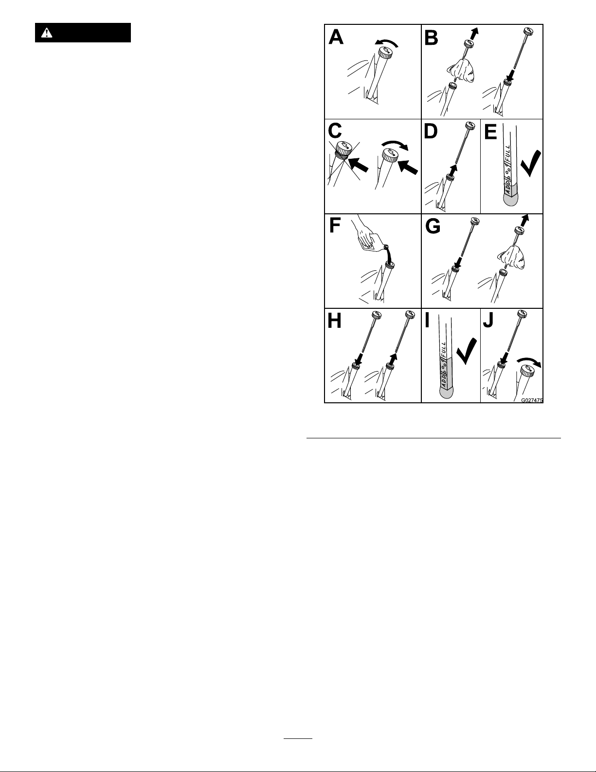
CheckingtheEngineOilLevel
ServiceInterval:Beforeeachuseordaily
g015155
Note:Checktheoilwhentheengineiscold.
38
Page 39
WARNING
Contactwithhotsurfacesmaycausepersonal
injury.
Keephands,feet,face,clothingandother
bodypartsawaythemuferandotherhot
surfaces.
Important:Donotoverllthecrankcasewithoil
becausedamagetotheenginemayresult.Donot
runenginewithoilbelowthelowmarkbecause
theenginemaybedamaged.
1.Parkthemachineonalevelsurface,disengage
thebladecontrolswitch,stoptheengine,
engageparkingbrake,andremovethekey.
2.Makesuretheengineisstopped,level,andis
coolsotheoilhashadtimetodrainintothe
sump.
3.T okeepdirt,grassclippings,etc.,outof
theengine,cleantheareaaroundtheoilll
cap/dipstickbeforeremovingit.
4.Stoptheengine,removethekey ,andwait
forallmovingpartstostopbeforeleavingthe
operatingposition(Figure45).
Figure45
g027475
39
Page 40

ChangingtheEngineOil
ServiceInterval:Aftertherst8hours—Changethe
engineoil.
Every100hours—Changetheengineoil(more
oftenindusty ,dirtyconditions).
Note:Disposeoftheusedoilatarecyclingcenter.
1.Parkthemachinesothatthedrainsideisslightly
lowerthantheoppositesidetoensuretheoil
drainscompletely.
2.DisengagethePTO,movethemotioncontrol
leverstotheneutrallockedpositionandsetthe
parkingbrake.
3.Stoptheengine,removethekey ,andwait
forallmovingpartstostopbeforeleavingthe
operatingposition(Figure46).
g027660
Figure47
Figure46
4.Slowlypourapproximately80%ofthespecied
oilintothellertubeandslowlyaddthe
additionaloiltobringittotheFullmark(Figure
47).
ChangingtheEngineOilFilter
ServiceInterval:Every200hours—Changetheoil
lter.(moreoftenindusty,dirty
conditions)
Note:Changetheengineoilltermorefrequently
whenoperatingconditionsareextremelydustyor
sandy.
1.Draintheoilfromtheengine;refertoChanging
theEngineOil.
2.Changetheengineoillter(Figure48).
g027539
40
Page 41

Figure48
2.Stoptheengine,removethekey ,andwait
forallmovingpartstostopbeforeleavingthe
operatingposition.
g027478
Figure49
Note:Duetothedeeprecessaroundthespark
plug,blowingoutthecavitywithcompressedair
isusuallythemosteffectivemethodforcleaning.
Thesparkplugismostaccessiblewhenthe
blowerhousingisremovedforcleaning.
CheckingtheSparkPlug
Important:Nevercleanthesparkplug(s).Always
replacethesparkplug(s)whenithas:ablack
coating,wornelectrodes,anoilylm,orcracks.
g027477
Ifyouseelightbrownorgrayontheinsulator,the
engineisoperatingproperly.Ablackcoatingonthe
insulatorusuallymeanstheaircleanerisdirty .
Note:Ensuretheoilltergaskettouchesthe
engineandthenanextra3/4turniscompleted.
3.Fillthecrankcasewiththepropertypeofnew
oil;refertoChangingtheOil.
ServicingtheSparkPlug
ServiceInterval:Every100hours—Checkthespark
plug(s).
Makesuretheairgapbetweenthecenterandside
electrodesiscorrectbeforeinstallingthesparkplug.
Useasparkplugwrenchforremovingandinstalling
thesparkplug(s)andagappingtool/feelergaugeto
checkandadjusttheairgap.Installanewspark
plug(s)ifnecessary.
Type:NGKBPR4ES(orequivalent)
AirGap:0.76mm(0.030inch)
RemovingtheSparkPlug
1.DisengagethePTO,movethemotioncontrol
leverstotheneutrallockedpositionandsetthe
parkingbrake.
Setthegapto0.030inches(0.76mm).
g027479
Figure50
InstallingtheSparkPlug
Tightenthesparkplug(s)to22N-m(16ft-lb).
41
Page 42

CleaningtheCooling
Figure51
FuelSystem
Maintenance
ReplacingtheFuelFilter
ServiceInterval:Every100hours/Yearly(whichever
comesrst)(moreoftenunder
dusty,dirtyconditions).
1.Disengagethebladecontrolswitch(PTO),move
themotioncontrolleverstotheneutrallock
position,andsettheparkingbrake.
2.Stoptheengine,removethekey ,andwait
g027661
forallmovingpartstostopbeforeleavingthe
operatingposition.
System
Cleantheairintakescreenfromgrassanddebris
beforeeachuse.
1.Disengagethebladecontrolswitchandmove
thecontrolleverstotheneutrallockedposition
andapplytheparkingbrake.
2.Stoptheengine,removethekey ,andwait
forallmovingpartstostopbeforeleavingthe
operatingposition.
3.Removetheairintakescreen,aircleanercover,
andfanhousing.
4.Cleandebrisandgrassfromtheparts.
5.Installtheairintakescreen,aircleanercover,
andfanhousing.
g027590
g027518
Figure52
42
Page 43

ElectricalSystem
Maintenance
ServicingtheBattery
ServiceInterval:Monthly
DANGER
Batteryelectrolytecontainssulfuricacid
whichisadeadlypoisonandcausessevere
burns.
Donotdrinkelectrolyteandavoidcontact
withskin,eyesorclothing.Wearsafety
glassestoshieldyoureyesandrubbergloves
toprotectyourhands.
RemovingtheBattery
WARNING
Batteryterminalsormetaltoolscouldshort
againstmetalmachinecomponentscausing
sparks.Sparkscancausethebatterygasses
toexplode,resultinginpersonalinjury.
•Whenremovingorinstallingthebattery,
donotallowthebatteryterminalstotouch
anymetalpartsofthemachine.
3.Removethewingnutsecuringthebatteryclamp
(Figure53).
Figure53
1.Removethewingnutand
clamp
2.Removethenegative
batterycablebeforethe
positive
4.Removetheclamp(Figure53).
5.Firstdisconnectthenegativebatterycable
(black)fromthenegative(-)(black)battery
terminal(Figure53).
3.Removethepositive
batterycable
4.Removebattery
g027672
•Donotallowmetaltoolstoshortbetween
thebatteryterminalsandmetalpartsofthe
machine.
WARNING
Incorrectbatterycableroutingcoulddamage
themachineandcablescausingsparks.
Sparkscancausethebatterygassesto
explode,resultinginpersonalinjury.
•AlwaysDisconnectthenegative(black)
batterycablebeforedisconnectingthe
positive(red)cable.
•AlwaysReconnectthepositive(red)
batterycablebeforereconnectingthe
negative(black)cable.
1.Disengagethebladecontrolswitch(PTO),move
themotioncontrolleverstotheneutrallock
positionandsettheparkingbrake.
2.Stoptheengine,removethekey ,andwait
forallmovingpartstostopbeforeleavingthe
operatingposition.
6.Slidetheredterminalbootoffthepositive(red)
batteryterminalandremovethepositive(+)(red)
batterycable(Figure53).
7.Removethebattery.
InstallingtheBattery
1.Positionbatteryinthetraywiththeterminal
postsoppositefromthefueltank(Figure53).
2.First,installthepositive(red)batterycableto
positive(+)batteryterminal.
3.Theninstallthenegativebatterycabletothe
negative(-)batteryterminal.
4.Securethecableswith2bolts,2washers,and
2locknuts(Figure53).
5.Slidetheredterminalbootontothepositive
(red)batterypost.
6.Installtheclampandsecureitwiththewingnut
(Figure53).
43
Page 44

ChargingtheBattery
WARNING
Chargingthebatteryproducesgassesthat
canexplode.
Neversmokenearthebatteryandkeepsparks
andamesawayfrombattery.
Important:Alwayskeepthebatteryfullycharged.
Thisisespeciallyimportanttopreventbattery
damagewhenthetemperatureisbelow32°F(0°C).
1.Chargebatteryfor10to15minutesat25to30
ampsor30minutesat10amps.
2.Whenthebatteryisfullycharged,unplug
thechargerfromtheelectricaloutlet,then
disconnectthechargerleadsfromthebattery
posts(Figure54).
3.Installthebatteryinthemachineandconnect
thebatterycables,refertoInstallingtheBattery.
1.Fuseblock
g024411
Figure55
2.30ampmainfuse
Figure54
1.PositiveBatteryPost
2.NegativeBatteryPost
3.Red(+)ChargerLead
4.Black(-)ChargerLead
ServicingtheFuses
Theelectricalsystemisprotectedbyfuses.Itrequires
nomaintenance;howeverifafuseblows,checkthe
component/circuitforamalfunctionorshort.
Important:Ensurethatthenewfusesare
thesametypeandamperageasthefuses
removed.
2.T oreplacetheenginefuse,removetheconsole
fromtheplasticfender.
g000960
g024412
Figure56
1.Enginefuse
Note:Thefusesarelocatedonrighthandconsole
nexttotheseat(Figure55).
Fuses:
•Main,30amp,blade-type
•Engine,20amp,blade-type
1.T oreplacethemainfuse,graspthefuseandpull
itstraightandawayfromthefuseblock.
3.Grasptheenginefuseandpullitstraightand
awayfromthefuseblock(Figure56).
4.Alignanewfusewiththeslotinthefuseblock
(Figure55).
5.Pushthefuseintothefuseblockuntilthefuse
isseated(Figure55).
44
Page 45

DriveSystem
HydraulicSystem
Maintenance
CheckingtheTirePressure
ServiceInterval:Every25hours—Checktire
pressure.
Maintaintheairpressureinthefrontandreartiresas
specied.Uneventirepressurecancauseuneven
cut.Checkthepressureatthevalvestem(Figure57).
Checkthetireswhentheyarecoldtogetthemost
accuratepressurereading.
Refertothemaximumpressuresuggestedbythetire
manufactureronthesidewallofthecasterwheeltires.
Inatethereardrivewheeltiresto13psi(90kPa).
Maintenance
HydraulicSystemOilSpecication
OilType:T oroHYPR-OIL®500or20w-50motoroil.
SystemCapacity:approximately4.495liter(152
oz)withalterchange.
Important:Useoilspeciedorequivalent.Other
uidscouldcausesystemdamage.
CheckingtheHydraulicOil Level
ServiceInterval:Every25hours
Checkexpansionreservoirandifnecessaryaddoil
totheFULLCOLDline.
1.Valvestem
g000554
Figure57
g010253
Figure58
1.Expansionreservoir3.Engine
2.FullColdline
ChangingtheHydraulic SystemFilterandOil
Thelterandoilarechangedatthesametime.Do
Notreuseoil.Oncethenewlterisinstalledandoilis
addedanyairinthesystemmustbepurged.
Thebleedingprocessisrepeateduntiltheoilremains
attheFULLCOLDlineinthereservoirafterpurging.
Failuretoproperlyperformthisprocedurecan
resultinirreparabledamagetothetransaxledrive
system.
45
Page 46

RemovingHydraulicSystem Filters
Important:Whenthehydraulicoillteris
removed,allofthehydraulicoilineachtransaxle
willdrainout.Useacontainerthatwillhandle
4.495liters(152oz)orlarger.
1.Stopengine,waitforallmovingpartstostop,
andallowenginetocool.Removethekeyand
engagetheparkingbrake.
2.Locatethelterandguardsoneachtransaxle
drivesystem(Figure59).Removethreescrews
securingthelterguardandguard.
Figure59
Rightsideshown
1.Transaxledrive
2.Oillter
3.Filterguard
4.Screws
5.Ventplug
3.Carefullycleantheareaaroundthelters.Itis
importantthatnodirtorcontaminationenterthe
hydraulicsystem.
4.Placeacontainerbelowtheltertocatchthe
oilthatdrainswhenthelterandventplugsare
removed.
5.Locateandremovetheventplugoneach
transmission
6.Unscrewtheltertoremoveandallowoilto
drainfromthedrivesystem.
Repeatthisprocedureforbothlters.
InstallingtheHydraulicSystem Filters
ServiceInterval:Aftertherst50hours
Every400hours
g027477
Figure60
g010254
1.Applyathincoatofoilonthesurfaceofthe
rubbersealofeachlter.
2.Turnthelterclockwiseuntilrubberseal
contactsthelteradapterthentightenthelter
anadditional3/4to1fullturn.Repeatforthe
otherlter
3.Installthelterguardsovereachlteras
previouslyremoved.Usethethreescrewsto
securethelterguards.
4.Verifytheventplugsareremovedbeforeadding
theoil.
5.Slowlypourthespeciedoilthroughexpansion
reservoiruntiloilcomesoutofoneofthevent
plugholes.Stopandinstallthatventplug.
Torquetheplugto20.3N-m(180in-lb).
6.Continuetoaddoilthroughtheexpansion
reservoiruntiloilcomesoutoftheremaining
ventplugholeonthesecondtransmission.Stop
andinstallthatventplug.Torquetheplugto
20.3N-m(180in-lb).
7.Continuetoaddoilthroughtheexpansion
reservoiruntilitreachestheFULLCOLDline
ontheexpansionreservoir.Proceedtothe
BleedingtheHydraulicSystemsection.
46
Page 47

Important:FailuretoperformtheBleeding
theHydraulicSystemprocedureafter
changinghydraulicltersandoilcanresult
inirreparabledamagetothetransaxledrive
system.
BleedingtheHydraulicSystem
1.Raisetherearofmachineupandsupportwith
jackstands(orequivalentsupport)justhigh
enoughtoallowdrivewheelstoturnfreely.
reachestheFULLCOLDlineontheexpansion
reservoirifnecessary.
Figure61
1.Jackingpoints
2.Entertheoperator'sposition.Startengine
andmovethrottlecontrolaheadto1/2throttle
position.Disengageparkingbrake.
A.Movethebypassleversintothepushing
themachineposition;refertothePushing
theMachinebyHandsectioninOperation.
Withthebypassvalvesopenandtheengine
running,slowlymovethemotioncontrol
leversinbothforwardandreverse(5or6
times).
B.Movethebypassleversintotheoperating
themachineposition.Withthebypassvalve
closedandtheenginerunning,slowlymove
thedirectionalcontrolinbothforwardand
reversedirections(5to6times).
C.Stoptheengineandchecktheoillevelin
theexpansionreservoir.Addthespecied
oilasuntilitreachestheFULLCOLDline
ontheexpansionreservoir.
g010333
3.Repeatstep2untilalltheairiscompletely
purgedfromthesystem.
Whenthetransaxleoperatesatnormalnoise
levelsandmovessmoothlyforwardand
reverseatnormalspeeds,thenthetransaxleis
consideredpurged.
4.Checktheoillevelintheexpansionreservoir
onelasttime.Addthespeciedoilasuntilit
47
Page 48

MowerDeck Maintenance
ServicingtheCutting Blades
Maintainsharpbladesthroughoutthecuttingseason
becausesharpbladescutcleanlywithouttearingor
shreddingthegrassblades.Tearingandshredding
turnsgrassbrownattheedges,whichslowsgrowth
andincreasesthechanceofdisease.
Checkthecutterbladesdailyforsharpness,and
foranywearordamage.Filedownanynicksand
sharpenthebladesasnecessary.Ifabladeis
damagedorworn,replaceitimmediatelywitha
genuineTororeplacementblade.Forconvenient
sharpeningandreplacement,youmaywanttokeep
extrabladesonhand.
WARNING
Awornordamagedbladecanbreak,anda
pieceofthebladecouldbethrownintothe
operator'sorbystander'sarea,resultingin
seriouspersonalinjuryordeath.
•Inspectthebladeperiodicallyforwearor
damage.
•Replaceawornordamagedblade.
g006530
Figure62
1.CuttingEdge3.Wear/slotForming
2.CurvedArea4.Crack
CheckingforBentBlades
Note:Themachinemustbeonalevelsurfacefor
thefollowingprocedure.
1.Raisethemowerdecktothehighest
height-of-cutposition;alsoconsideredthe
'transport'position.
2.Whilewearingthicklypaddedglovesorother
adequatehandprotectionslowlyrotatebladeto
bemeasuredintoapositionthatallowseffective
measurementofthedistancebetweenthe
cuttingedgeandthelevelsurfacethemachine
ison.
BeforeInspectingorServicingthe Blades
Parkthemachineonalevelsurface,disengagethe
bladecontrolswitch(PTO),andsettheparkingbrake.
TurntheignitionkeytoOff.Removethekey.
InspectingtheBlades
ServiceInterval:Beforeeachuseordaily
1.Inspectthecuttingedges(Figure62).Ifthe
edgesarenotsharporhavenicks,removeand
sharpentheblades.RefertoSharpeningthe
Blades.
2.Inspecttheblades,especiallythecurvedarea
(Figure62).Ifyounoticeanydamage,wear,ora
slotforminginthisarea(Figure62),immediately
installanewblade.
g014972
Figure63
1.Deck3.Blade
2.Spindlehousing
3.Measurefromthetipofthebladetotheat
surfacehere.
48
Page 49

Figure64
g014973
Figure66
g014973
1.Blade,inpositionformeasuring
2.Levelsurface
3.Measureddistancebetweenbladeandsurface(A)
4.Rotatethesameblade180degreessothat
theopposingcuttingedgeisnowinthesame
position.
Figure65
1.Blade,sidepreviouslymeasured
2.Measurementpositionusedpreviously
3.Opposingsideofbladebeingmovedintomeasurement
position
5.Measurefromthetipofthebladetotheat
surfacehere.Thevarianceshouldbenomore
than3mm(1/8inch).
1.Opposingbladeedge,inpositionformeasuring
2.Levelsurface
3.Secondmeasureddistancebetweenbladeandsurface(B)
WARNING
Abladethatisbentordamagedcould
breakapartandcouldseriouslyinjureor
killyouorbystanders.
•Alwaysreplacebentordamaged
bladewithanewblade.
•Neverleorcreatesharpnotchesin
theedgesorsurfacesofblade.
A.IfthedifferencebetweenAandBisgreater
g014974
than3mm(1/8inch)replacethebladewith
anewblade.RefertoRemovingtheBlades
andInstallingtheBlades.
Note:Ifabentbladeisreplacedwithanew
oneandthedimensionobtainedcontinues
toexceed3mm(1/8inch),thebladespindle
couldbebent.ContactanAuthorizedToro
Dealerforservice.
B.Ifthevarianceiswithinconstraints,moveto
thenextblade.
Repeatthisprocedureoneachblade.
RemovingtheBlades
Bladesmustbereplacedifasolidobjectishit,ifthe
bladeisoutofbalanceorisbent.T oensureoptimum
performanceandcontinuedsafetyconformanceof
themachine,usegenuineTororeplacementblades.
Replacementbladesmadebyothermanufacturers
mayresultinnon-conformancewithsafetystandards.
Holdthebladeendusingaragorthickly-padded
glove.Removethebladebolt,curvedwasher,and
bladefromthespindleshaft(Figure67).
49
Page 50
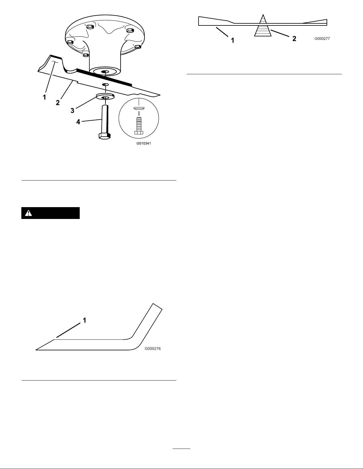
Figure69
1.Blade2.Balancer
InstallingtheBlades
1.Installthebladeontothespindleshaft(Figure
67).
Important:Thecurvedpartoftheblade
mustbepointingupwardtowardtheinside
ofthemowertoensurepropercutting.
g000277
Figure67
1.SailAreaofBlade3.Curvedwasher
2.Blade4.BladeBolt
SharpeningtheBlades
WARNING
Whensharpeningblade,piecesofbladecould
bethrownandcauseseriousinjury.
Wearpropereyeprotectionwhensharpening
blade.
1.Usealetosharpenthecuttingedgeatboth
endsoftheblade(Figure68).Maintainthe
originalangle.Thebladeretainsitsbalanceif
thesameamountofmaterialisremovedfrom
bothcuttingedges.
g010341
2.Installthespringdiskandbladebolt.The
springdiskconemustbeinstalledtowardthe
bolthead(Figure67).Torquethebladeboltto
135-150N-m(100-110ft-lb).
Figure68
1.Sharpenatoriginalangle
2.Checkthebalanceofthebladebyputtingiton
abladebalancer(Figure69).Ifthebladestays
inahorizontalposition,thebladeisbalanced
andcanbeused.Ifthebladeisnotbalanced,
lesomemetalofftheendofthesailareaonly
(Figure67).Repeatthisprocedureuntilthe
bladeisbalanced.
g000276
50
Page 51

MowerDeckLeveling
Checktoensurethemowerdeckislevelanytimeyou
installthemowerorwhenyouseeanunevencuton
yourlawn.
Themowerdeckmustbecheckedforbentblades
priortoleveling;anybentbladesmustberemoved
andreplaced.RefertotheCheckingforBentBlades
procedurebeforecontinuing.
Themowerdeckmustbeleveledside-to-siderst
thenthefronttorearslopecanbeadjusted.
Requirements:
•Themachinemustbeonalevelsurface.
•Allfourtiremustbeproperlyinated.Referto
CheckingtheTirePressureintheDriveSystem
Maintenancesection.
CheckingSide-to-SideLevel
Themowerbladesmustbelevelfromsidetoside.
Checktheside-to-sidelevelanytimeyouinstallthe
mowerorwhenyouseeanunevencutonyourlawn.
CheckingtheFront-to-RearBlade Slope
Checkthefront-to-rearbladelevelanytimeyouinstall
themower.Ifthefrontofthemowerismorethan
7.9mm(5/16inch)lowerthantherearofthemower,
adjustthebladelevelusingthefollowinginstructions:
1.Parkthemachineonalevelsurfaceand
disengagethebladecontrolswitch.
2.Movethemotioncontrolleversoutwardtothe
neutralposition,engagetheparkingbrake,
stoptheengine,removethekey ,andwaitfor
allmovingpartstostopbeforeleavingthe
operatingposition.
3.Carefullyrotatethebladessotheyarefacing
fronttorear(Figure71).
4.Measurefromthetipofthefrontbladetotheat
surfaceandthetipoftherearbladetotheat
surface(Figure71).Ifthefrontbladetipisnot
1.6-7.9mm(1/16-5/16inch)lowerthantherear
bladetip,continuetotheLevelingtheMower
Deckprocedure.
1.Parkthemachineonalevelsurfaceand
disengagethebladecontrolswitch.
2.Movethemotioncontrolleversoutwardtothe
neutrallockposition,stoptheengine,remove
thekey ,settheparkingbrakeandwaitfor
allmovingpartstostopbeforeleavingthe
operatingposition.
3.Carefullyrotatethebladessidetoside.
4.Measurebetweentheoutsidecuttingedges
andtheatsurface(Figure70).Ifboth
measurementsarenotwithin5mm(3/16inch),
anadjustmentisrequired;continuetothe
Levelingprocedure.
Figure70
1.Bladessidetoside
2.Outsidecuttingedges
3.Measurefromthetipofthe
bladetotheatsurface
here
g007199
Figure71
1.Bladesfronttorear3.Measurefromthetipofthe
2.Outsidecuttingedges
bladetotheatsurface
here
LevelingtheMowerDeck
1.Setanti-scalprollerstotopholesorremove
completelyforthisprocedure;refertoAdjusting
theAnti-ScalpRollers(page26).
2.Settheheight-of-cutlevertothe76mm(3inch)
position;refertoAdjustingtheHeight-of-Cut
g007202
(page25).
3.Placetwo6.66cm(2-5/8inch)blocksunder
eachsideofthefrontedgeofthedeck,butnot
undertheanti-scalprollerbrackets(Figure72).
4.Placetwo7.30cm(2-7/8inch)thickblocks
undertherearedgeofthecuttingdeckskirt;one
oneachsideofthecuttingdeck(Figure72).
51
Page 52

InspectingtheBelts
ServiceInterval:Every50hours
Checkthebeltsforsquealingwhenthebeltisrotating,
bladesslippingwhencuttinggrass,frayedbeltedges,
burnmarksandcracksaresignsofawornmower
belt.Replacethemowerbeltifanyoftheseconditions
areevident.
ReplacingtheMowerBelt
Figure72
1.Woodblock,6.66cm
(2-5/8inch)thick
2.Woodblock,7.30cm
(2-7/8inch)thick
3.Frontedge
5.Loosentheadjustmentboltsonallfourcorners
sothatthedeckissittingsecurelyonallfour
blocks(Figure73).
g024428
Squealingwhenthebeltisrotating,bladesslipping
whencuttinggrass,frayedbeltedges,burnmarks
andcracksaresignsofawornmowerbelt.Replace
themowerbeltifanyoftheseconditionsareevident.
1.Disengagethebladecontrolswitch(PTO),move
themotioncontrolleverstotheneutrallocked
positionandsettheparkingbrake.
2.Stoptheengine,removethekey ,andwait
forallmovingpartstostopbeforeleavingthe
operatingposition.
3.Lowerthemowertothe76mm(3inch)
height-of-cutposition.
4.Loosenthebottomtwoboltsholdingthe
mower-deckcurtaintothemowerdeck.Referto
ReleasingtheMower-DeckCurtain(page37).
5.Foreachofthebeltcovers,loosenthetwobolts
butdonotremovethem.Slidethecoveruntil
itisclearoftheboltsandliftitupandoutto
removeit.
6.Removetheoorpantoaccesstheidlerpulley;
refertotheRemovingtheFloorPanprocedure
inPremaintenance.
Figure73
1.Deckliftarm
2.Chain
3.Hook
4.Adjustmentbolt
6.Ensurethereistensiononallfourchains(Figure
73).
7.Tightenthefouradjustmentbolts(Figure73).
8.Checkthatblockstjustsnuglyunderthedeck
skirt.Makesureallboltsaretight
9.Verifythatthedeckislevelbycheckingthe
side-to-sidelevelandfront-to-rearbladeslope;
repeatthedecklevelingprocedureifnecessary.
7.Usingaspringremovaltool,(T oropartno.
92-5771),removetheidlerspringfromthe
deckposttoremovetensionontheidlerpulley
(Figure74).
g024313
52
Page 53

Figure74
1.Springremovaltool(T oro
partno.92-5771)
2.Idlerspring5.Mowerbelt
3.Deckpost
8.Lowerthemowertothelowestheight-of-cut.
Placetheheight-of-cutpininthelockposition
forlowestheight-of-cut.
4.Idlerarm
RemovingtheMower
Parkthemachineonalevelsurfaceanddisengage
thebladecontrolswitch.Movethemotioncontrol
leversoutwardtotheneutralposition,engageparking
brake,stoptheengine,removethekey ,andwaitfor
allmovingpartstostopbeforeleavingtheoperating
position.
Lowerthemowertothelowestheight-of-cut.Select
oneofthefollowingproceduresdependingonthe
mowerdecksizeinstalledtocompletetheremoval.
PreparingtoRemovetheMower Deck
g009806
1.Lowerthemowertothe76mm(3inch)
height-of-cutposition.
2.Loosenthebottomtwoboltsholdingthe
mower-deckcurtaintothemowerdeck.Referto
ReleasingtheMower-DeckCurtain(page37).
3.Removethemowerbeltfromtheenginepulley;
refertoReplacingtheMowerBelt(page52).
9.Removethebeltfromthemowerdeckpulleys
andremovetheexistingbelt.
10.Installthenewbeltaroundthemowerpulleys
andtheclutchpulleyundertheengine(Figure
74).
WARNING
Thespringisundertensionwhen
installedandcancausepersonalinjury .
Becarefulwhenremovingthebelt.
11.Usingaspringremovaltool,(T oropartno.
92-5771),installtheidlerspringoverthedeck
postandplacingtensionontheidlerpulleyand
mowerbelt(Figure74).
12.Ensurethatthebeltisproperlyseatedinall
pulleys.
13.T oinstallthebeltcovers,insertthetabsonthe
eachcoverintothecorrespondingslotsonthe
deckbracket,ensuringthattheyseat.Rotate
thecovertothedeckandslidethenotches
undertheloosenedboltsuntiltheyareseated.
Tightentheboltstosecurethecovertothedeck.
14.Tightenthebottomtwoboltsholdingthe
mower-deckcurtaintothemowerdeck(
ReleasingtheMower-DeckCurtain(page37)).
53
Page 54

RemovingtheMowerDeck
1.Removethehairpincotterandwashersecuring
thelong,linkpintotheframeanddeck;remove
thelinkbar(Figure75).
Figure75
1.Linkpin3.Hairpincotter
2.Washer
2.Liftuponthemowerdecktorelievetensionfrom
themowerdeck.
3.Removethechainsfromthehooksonthedeck
liftarms(Figure76).
InstallingtheMowerDeck
1.Parkthemachineonalevelsurfaceand
disengagethebladecontrolswitch.
2.Movethemotioncontrolleversoutwardtothe
neutrallockposition,stoptheengine,remove
thekey ,settheparkingbrakeandwaitfor
allmovingpartstostopbeforeleavingthe
operatingposition.
3.Slidethemowerunderthemachine.
4.Lowertheheight-of-cutlevertothelowest
position.
5.Placetheheight-of-cutpininthelockposition
forlowestheight-of-cut.
g024314
6.Lifttherearofthemowerdeckandattachthe
chainstotherearliftarms(Figure76).
7.Attachthefrontchainstothefrontliftarms
(Figure76).
8.Installthelong,linkbarthroughtheframe
hangeranddeck.
9.Securethelinkpinwiththehairpincottersand
washersremovedpreviously(Figure75).
10.Installthemowerbeltontotheenginepulley;
refertoReplacingtheMowerBelt(page52).
Figure76
1.Deckliftarm
2.Chain
4.Raisetheheight-of-cuttothetransportposition.
5.Removethebeltfromtheclutchpulleyonthe
engine.
6.Slidethemoweroutfromunderneaththe
machine.
3.Hook
4.Adjustmentbolt
Note:Retainallpartsforfutureinstallation.
11.Tightenthebottomtwoboltsholdingthe
mower-deckcurtaintothemowerdeck(Figure
41).
ReplacingtheGrass
Deector
ServiceInterval:Beforeeachuseordaily—Inspect
thegrassdeectorfordamage
WARNING
Anuncovereddischargeopeningcould
allowthelawnmowertothrowobjectsinthe
operator’sorbystander’sdirectionandresult
inseriousinjury.Also,contactwiththeblade
g024313
couldoccur.
Neveroperatethelawnmowerunlessyou
installamulchplate,dischargedeector,or
grasscollectionsystem.
Inspectthegrassdeectorfordamagebeforeeach
use.Replaceanydamagedpartsbeforeuse.
1.Removethecotterpinfromtheendoftherod
(Figure77).
2.Disengagethespringfromthenotchinthe
deectorbracketandslidetherodoutofthe
weldeddeckbrackets,spring,anddischarge
54
Page 55

deector(Figure77).Removethedamagedor
worndischargedeector.
Figure77
1.Deector4.Spring
2.Deckbrackets
3.Rod
5.Springinstalledoverthe
rod
6.Cotterpin
3.Positionthenewdischargedeectorwiththe
bracketendsbetweentheweldedbracketson
thedeckasshowninFigure77.
4.Installthespringontothestraightendoftherod.
Positionthespringontherodasshowninso
theshorterspringendiscomingfromunderthe
rodbeforethebendandgoingovertherodasit
returnsfromthebend.
g024316
Figure78
g028042
1.Rodandspringassembly
partiallyinstalled
2.Loopendofthespring
installedintothenotchin
thedeectorbracket
3.Rod,shortend,moved
behindmowerbracket
4.Shortend,retainedby
mowerbracket.
6.Securetherodandspringassemblybytwistingit
sotheshortendoftherodcanbeplacedbehind
thefrontbracketweldedtothedeck(Figure78).
Important:Thegrassdeectormustbe
springloadedinthedownposition.Liftthe
deectoruptotestthatitsnapstothefull
downposition.
7.Installthecotterpinintotheendoftherod
(Figure77).
5.Lifttheloopendofthespringandplaceitinto
thenotchonthedeectorbracket(Figure78).
55
Page 56

Cleaning
WashingtheUndersideof theMower
ServiceInterval:Aftereachuse—Cleanthemower
housing.
Washtheundersideofthemoweraftereachuseto
preventgrassbuildupforimprovedmulchactionand
clippingdispersal.
1.Parkthemachineonalevelsurfaceand
disengagethebladecontrolswitch.
2.Movethemotioncontrolleversoutwardtothe
neutrallockposition,stoptheengine,remove
thekey,andwaitforallmovingpartstostop
beforeleavingtheoperatingposition.
3.Attachthehosecouplingtotheendofthe
mowerwashouttting,andturnthewateron
high(Figure79).
Note:Spreadpetroleumjellyonthewashout
ttingO-ringtomakethecouplingslideon
easierandprotecttheO-ring.
Figure79
1.Washoutttinglocations
on54inchdecks
2.Washoutttinglocations
on48inchdecks
3.Washouttting6.Coupling
g010344
4.O-ring
5.Hose
4.Lowerthemowertothelowestheight-of-cut.
5.Sitontheseatandstarttheengine.Engagethe
bladecontrolswitchandletthemowerrunfor
onetothreeminutes.
6.Disengagethebladecontrolswitch,stopthe
engine,andremovetheignitionkey.Waitforall
movingpartstostop.
7.Turnthewateroffandremovethecouplingfrom
thewashouttting.
Note:Ifthemowerisnotcleanafterone
washing,soakitandletitstandfor30minutes.
Thenrepeattheprocess.
8.Runthemoweragainforonetothreeminutesto
removeexcesswater.
56
Page 57

WARNING
Abrokenormissingwashouttting
couldexposeyouandotherstothrown
objectsorbladecontact.Contactwith
bladeorthrowndebriscancauseinjury
ordeath.
•Replacebrokenormissingwashout
ttingimmediately,beforeusing
moweragain.
•Neverputyourhandsorfeetunder
themowerorthroughopeningsinthe
mower.
WasteDisposal
Engineoil,batteries,hydraulicoil,andenginecoolant
arepollutantstotheenvironment.Disposeofthese
accordingtoyourstateandlocalregulations.
Storage
CleaningandStorage
1.Disengagethebladecontrolswitch(PTO),set
theparkingbrake,andturntheignitionkeyto
Off.Removethekey.
2.Removegrassclippings,dirt,andgrimefromthe
externalpartsoftheentiremachine,especially
theengineandhydraulicsystem.Cleandirtand
chafffromtheoutsideoftheenginecylinder
headnsandblowerhousing.
Important:Youcanwashthemachinewith
milddetergentandwater.Donotpressure
washthemachine.Avoidexcessiveuse
ofwater,especiallynearthecontrolpanel,
engine,hydraulicpumps,andmotors.
3.Checktheparkingbrakeoperation;referto
OperatingtheParkingBrake(page21).
4.Servicetheaircleaner;refertoServicingtheAir
Cleaner(page38).
5.Greasethemachine;refertoLubrication(page
37).
6.Changethecrankcaseoil;refertoChangingthe
EngineOil(page40).
7.Checkthetirepressure;refertoCheckingthe
TirePressure(page45).
8.Changethehydrauliclter;refertoChanging
theHydraulicSystemFilterandOil(page45).
9.Chargethebattery;refertoChargingtheBattery
(page44).
10.Scrapeanyheavybuildupofgrassanddirt
fromtheundersideofthemower,thenwashthe
mowerwithagardenhose.
Note:Runthemachinewiththebladecontrol
switch(PTO)engagedandtheengineathigh
idlefor2to5minutesafterwashing.
11.Checktheconditionoftheblades;referto
ServicingtheCuttingBlades(page48).
12.Preparethemachineforstoragewhennon-use
occursover30days.Preparethemachinefor
storageasfollows:
A.Addapetroleumbased
stabilizer/conditionertofuelinthe
tank.Followmixinginstructionsfrom
thestabilizermanufacturer.Donotuse
analcoholbasedstabilizer(ethanolor
methanol).
Note:Afuelstabilizer/conditionerismost
effectivewhenmixedwithfreshfueland
usedatalltimes.
57
Page 58

B.Runtheenginetodistributeconditionedfuel
throughthefuelsystem(5minutes).
C.Stoptheengine,allowittocool,anddrain
thefueltank.
D.Restarttheengineandrunituntilitstops.
E.Disposeoffuelproperly.Recyclethefuel
accordingtolocalcodes.
Important:Donotstore
stabilizer/conditionedfuelover
90days.
13.Checkandtightenallbolts,nuts,andscrews.
Repairorreplaceanypartthatisdamaged.
14.Paintallscratchedorbaremetalsurfaces.Paint
isavailablefromyourAuthorizedServiceDealer.
15.Storethemachineinaclean,drygarageor
storagearea.Removethekeyfromtheignition
switchandkeepitoutofreachofchildrenor
otherunauthorizedusers.Coverthemachineto
protectitandkeepitclean.
58
Page 59

Troubleshooting
Problem
Starterdoesnotcrank
Enginewillnotstart,startshard,orfails
tokeeprunning
PossibleCauseCorrectiveAction
1.Bladecontrolswitch(PTO)isengaged.1.Movebladecontrolswitch(PTO)to
2.Parkingbrakeisnoton.
3.Driveleversarenotinneutrallock
position.
4.Operatorisnotseated.4.Sitontheseat.
5.Batteryisdead.
6.Electricalconnectionsarecorrodedor
loose.
7.Fuseisblown.
8.Relayorswitchisdefective.8.ContactanAuthorizedServiceDealer.
1.Fueltankisempty.
2.Fuelshutoffvalveisclosed.2.Openthefuelshutoffvalve.
3.Oillevelinthecrankcaseislow.
4.Thethrottleandchokearenotinthe
correctposition.
5.Dirtinfuellter.5.Replacethefuellter.
6.Dirt,water,orstalefuelisinthefuel
system.
7.Aircleanerisdirty.
8.Seatswitchisnotfunctioningproperly.
9.Electricalconnectionsarecorroded,
looseorfaulty.
10.Relayorswitchisdefective.10.ContactanAuthorizedServiceDealer.
11.Faultysparkplug.
12.Sparkplugwireisnotconnected.12.Checkthesparkplugwireconnection.
disengaged.
2.Settheparkingbrake.
3.Ensurethedriveleversareinthe
neutrallockposition.
5.Chargethebattery.
6.Checktheelectricalconnectionsfor
goodcontact.
7.Replacefuse.
1.Fillthefueltank.
3.Addoiltothecrankcase.
4.Besurethethrottlecontrolismidway
betweenthe“SLOW”and“FAST”
positions,andthechokeisinthe“ON”
positionforacoldengineorthe“OFF”
positionforawarmengine.
6.ContactanAuthorizedServiceDealer.
7.Cleanorreplacetheaircleaner
element.
8.Checktheseatswitchindicator.
Replaceseatifneeded.
9.Checktheelectricalconnections
forgoodcontact.Cleanconnector
terminalsthoroughlywithelectrical
contactcleaner,applydielectricgrease
andreconnect.
11.Clean,adjustorreplacesparkplug.
Enginelosespower.
Engineoverheats.
Mowerpullsleftorright(withleversfully
forward)
1.Engineloadisexcessive.1.Reducethegroundspeed.
2.Aircleanerisdirty.
3.Oillevelinthecrankcaseislow.
4.Coolingnsandairpassagesabove
theengineareplugged.
5.Ventholeinthefuelcapisplugged.5.Cleanorreplacethefuelcap.
6.Dirtinthefuellter.6.Replacethefuellter.
7.Dirt,water,orstalefuelisinthefuel
system.
1.Engineloadisexcessive.1.Reducethegroundspeed.
2.Oillevelinthecrankcaseislow.
3.Coolingnsandairpassagesabove
theengineareplugged.
1.Trackingneedsadjustment1.Adjustthetracking.
2.Tirepressureindrivetiresnotcorrect.2.Adjusttirepressureinthedrivetires.
2.Cleantheaircleanerelement.
3.Addoiltothecrankcase.
4.Removetheobstructionfromthe
coolingnsandairpassages.
7.ContactanAuthorizedServiceDealer.
2.Addoiltothecrankcase.
3.Removetheobstructionfromthe
coolingnsandairpassages.
59
Page 60

Problem
PossibleCauseCorrectiveAction
Machinedoesnotdrive.
Abnormalvibration.
Unevencuttingheight.
1.Bypassvalvesisnotclosedtight.1.Tightenthebypassvalves.
2.Pumpbeltisworn,looseorbroken.
3.Pumpbeltisoffapulley .3.Changethebelt.
4.Brokenormissingidlerspring.4.Replacethespring.
5.Hydraulicoillevelislowortoohot.5.Addhydraulicoiltoreservoirsorletit
1.Cuttingblade(s)is/arebentor
unbalanced.
2.Blademountingboltisloose.2.Tightentheblademountingbolt.
3.Enginemountingboltsareloose.3.Tightentheenginemountingbolts.
4.Looseenginepulley ,idlerpulley,or
bladepulley .
5.Enginepulleyisdamaged.
6.Bladespindleisbent.
7.Motormountislooseorworn.
1.Blade(s)notsharp.1.Sharpentheblade(s).
2.Cuttingblade(s)is/arebent.2.Installnewcuttingblade(s).
3.Mowerdeckisnotlevel.
4.Undersideofmowerisdirty .4.Cleantheundersideofthemower .
5.Tirepressureisnotcorrect.5.Adjustthetirepressure.
6.Bladespindlebent.
2.Changethebelt.
cooldown.
1.Installnewcuttingblade(s).
4.Tightentheappropriatepulley.
5.ContactanAuthorizedServiceDealer.
6.ContactanAuthorizedServiceDealer.
7.ContactanAuthorizedServiceDealer.
3.Levelmowerdeckfromside-to-side
andfront-to-rear.
6.ContactanAuthorizedServiceDealer.
Bladesdonotrotate.
1.Mowerdeckbeltisworn,looseor
broken.
2.Mowerdeckbeltisoffpulley.
3.Pumpdrivebeltisworn,looseor
broken.
4.Brokenormissingidlerspring.4.Replacethespring.
1.Installnewdeckbelt.
2.Installmowerdeckpulleyandcheck
theidlerpulley,idlerarmandspringfor
correctpositionandfunction.
3.Checkthebelttensionorinstallnew
belt.
60
Page 61

Schematics
WireDiagram(Rev .B)
61
g028048
Page 62

Notes:
Page 63

InternationalDistributorList
Distributor:
AgrolancKft
BalamaPrimaEngineeringEquip.HongKong85221552163
B-RayCorporation
CascoSalesCompany
CeresS.A.CostaRica
CSSCTurfEquipment(pvt)Ltd.SriLanka
CyrilJohnston&Co.
CyrilJohnston&Co.RepublicofIreland
EquiverMexico525553995444ParklandProductsLtd.NewZealand6433493760
FemcoS.A.Guatemala
ForGarderOU
G.Y .K.CompanyLtd.
GeomechanikiofAthensGreece
GolfinternationalTurizm
GuandongGoldenStarChina
HakoGroundandGardenSweden
HakoGroundandGarden
HayterLimited(U.K.)
HydroturfInt.CoDubai
HydroturfEgyptLLC
IrrimacPortugal351212388260T oroEuropeNVBelgium3214562960
IrrigationProductsInt'lPvtLtd.India0091442449
JeanHeybroekb.v.Netherlands31306394611VictusEmakPoland48618238369
Country:
Hungary3627539640
Korea82325512076
PuertoRico7877888383
NorthernIreland442890813121
Estonia3723846060
Japan81726325861
Turkey902163365993Riversa
Norway4722907760
UnitedKingdom441279723444
UnitedArabEmirates97143479479T-MarktLogisticsLtd.Hungary3626525500
Egypt2025194308ToroAustraliaAustralia61395807355
PhoneNumber:Distributor:
5062391138
94112746100
442890813121
5024423277
30109350054
862087651338
4635100000
4387
Country:
MaquiverS.A.Colombia
MaruyamaMfg.Co.Inc.
Mountelda.s.CzechRepublic
Mountelda.s.Slovakia
MunditolS.A.
NormaGarden
OslingerTurfEquipmentSA
OyHakoGroundandGarden
Ab
Perfetto
PratoverdeSRL.
Prochaska&Cie
RTCohen2004Ltd.
LelyTurfcare
SolvertS.A.S.
SpyprosStavrinidesLimitedCyprus
SurgeSystemsIndiaLimited
ValtechMorocco21253766
Japan81332522285
Argentina54114821
Russia74954116120
Ecuador59342396970
Finland35898700733
Poland48618208416
Italy390499128
Austria4312785100
Israel97298617979
Spain
Denmark4566109200
France331308177
India911292299901
Phone
Number:
5712364079
420255704
220
420255704
220
9999
128
34952837500
00
35722434131
3636
EuropeanPrivacyNotice
TheInformationT oroCollects
ToroWarrantyCompany(T oro)respectsyourprivacy.Inordertoprocessyourwarrantyclaimandcontactyouintheeventofaproductrecall,weaskyou
tosharecertainpersonalinformationwithus,eitherdirectlyorthroughyourlocalT orocompanyordealer .
TheT orowarrantysystemishostedonserverslocatedwithintheUnitedStateswhereprivacylawmaynotprovidethesameprotectionasapplies
inyourcountry.
BYSHARINGYOURPERSONALINFORMATIONWITHUS,YOUARECONSENTINGTOTHEPROCESSINGOFYOURPERSONALINFORMA TION
ASDESCRIBEDINTHISPRIV ACYNOTICE.
TheWayT oroUsesInformation
Toromayuseyourpersonalinformationtoprocesswarrantyclaims,tocontactyouintheeventofaproductrecallandforanyotherpurposewhichwetell
youabout.ToromayshareyourinformationwithT oro'safliates,dealersorotherbusinesspartnersinconnectionwithanyoftheseactivities.Wewillnot
sellyourpersonalinformationtoanyothercompany.Wereservetherighttodisclosepersonalinformationinordertocomplywithapplicablelawsand
withrequestsbytheappropriateauthorities,tooperateoursystemsproperlyorforourownprotectionorthatofotherusers.
RetentionofyourPersonalInformation
Wewillkeepyourpersonalinformationaslongasweneeditforthepurposesforwhichitwasoriginallycollectedorforotherlegitimatepurposes
(suchasregulatorycompliance),orasrequiredbyapplicablelaw .
Toro'sCommitmenttoSecurityofY ourPersonalInformation
Wetakereasonableprecautionsinordertoprotectthesecurityofyourpersonalinformation.Wealsotakestepstomaintaintheaccuracyandcurrent
statusofpersonalinformation.
AccessandCorrectionofyourPersonalInformation
Ifyouwouldliketorevieworcorrectyourpersonalinformation,pleasecontactusbyemailatlegal@toro.com.
AustralianConsumerLaw
AustraliancustomerswillnddetailsrelatingtotheAustralianConsumerLaweitherinsidetheboxoratyourlocalToroDealer.
374-0269RevH
Page 64

TheToroWarranty
TheToroGTSStartingGuarantee
ResidentialProducts
and
ConditionsandProductsCovered
TheToroCompanyanditsafliate,ToroWarrantyCompany,pursuant
toanagreementbetweenthem,jointlypromisetorepairfortheoriginal
purchaser
workmanshiporiftheT oroGTS(GuaranteedtoStart)enginewillnotstart
ontherstorsecondpull,providedtheroutinemaintenancerequiredinthe
Operator'sManualhavebeenperformed.
Thefollowingtimeperiodsapplyfromthedateofpurchase:
ProductsWarrantyPeriod
WalkPowerMowers
•CastDeck
•Engine
•Battery2years
•SteelDeck
•Engine
TimeMasterMowers3yearsResidentialUse
•Engine
•Battery2years
ElectricHandHeldProducts
andWalkPowerMowers
Snowthrowers
•SingleStage
•Engine
•TwoStage
•Chute,chutedeectorand
ElectricSnowthrowers
AllRide-OnUnitsBelow
•Engine
•Battery2yearsResidentialUse
•Attachments2yearsResidentialUse
DHLawn&GardenTractors
XLSLawn&GardenTractors
TimeCutter
TITANMowers3yearsor240hours
•Frame
1
OriginalPurchasermeansthepersonwhooriginallypurchasedtheToroProduct.
2
Residentialusemeansuseoftheproductonthesamelotasyourhome.Useatmorethanone
locationisconsideredcommercialuseandthecommercialusewarrantywouldapply.
3
TheToroGTSStartingGuaranteedoesnotapplywhentheproductisusedcommercially .
4
SomeenginesusedonToroProductsarewarrantedbytheenginemanufacturer .
5
Whicheveroccursrst.
6
LifetimeFrameW arranty-Ifthemainframe,consistingofthepartsweldedtogethertoformthe
tractorstructurethatothercomponentssuchastheenginearesecuredto,cracksorbreaksin
normaluse,itwillberepairedorreplaced,atToro'soption,underwarrantyatnocostforpartsand
labor.Framefailureduetomisuseorabuseandfailureorrepairrequiredduetorustorcorrosion
arenotcovered.
Warrantymaybedeniedifthehourmeterisdisconnected,altered,or
showssignsofbeingtamperedwith.
1
impellerhousingcover
theToroProductlistedbelowifdefectiveinmaterialsor
5yearsResidentialUse
90DaysCommercialUse
5yearsGTSGuarantee,
ResidentialUse
3
2yearsResidentialUse
30DaysCommercialUse
2yearsGTSGuarantee,
ResidentialUse
3
90DaysCommercialUse
3yearsGTSGuarantee,
ResidentialUse
3
2yearsResidentialUse
NoWarrantyforCommercial
Use
2yearsResidentialUse
45DaysCommercialUse
2yearsGTSGuarantee,
ResidentialUse
3
3yearsResidentialUse
45DaysCommercialUse
Lifetime(originalowneronly)
2yearsResidentialUse
NoWarrantyforCommercialUse
Seeenginemanufacturer'swarranty
2yearsResidentialUse
30DaysCommercialUse
3yearsResidentialUse
30DaysCommercialUse
3yearsResidentialUse
30DaysCommercialUse
5
Lifetime(originalowneronly)
2
2
2
2
2
2
5
2
2
2
2
2
2
6
OwnerResponsibilities
YoumustmaintainyourToroProductbyfollowingthemaintenance
proceduresdescribedintheOperator'sManual.Suchroutinemaintenance,
whetherperformedbyadealerorbyyou,isatyourexpense.
InstructionsforObtainingWarrantyService
IfyouthinkthatyourT oroProductcontainsadefectinmaterialsor
workmanship,followthisprocedure:
1.Contactyoursellertoarrangeserviceoftheproduct.Ifforany
reasonitisimpossibleforyoutocontactyourseller,youmaycontact
anyToroAuthorizedDistributortoarrangeservice.Seeattached
DistributorList.
2.Bringtheproductandyourproofofpurchase(salesreceipt)tothe
servicingoutlet.Ifforanyreasonyouaredissatisedwiththeservicing
outlet’sanalysisorwiththeassistanceprovided,contactusat:
ToroCustomerCareDepartment,RLCDivision
ToroWarrantyCompany
811 1LyndaleAvenueSouth
Bloomington,MN55420-1196
001–952–948–4707
ItemsandConditionsNotCovered
Thereisnootherexpresswarrantyexceptforspecialemissionsystem
coverageandenginewarrantycoverageonsomeproducts.Thisexpress
warrantydoesnotcoverthefollowing:
•Costofregularmaintenanceserviceorparts,suchaslters,fuel,
lubricants,oilchanges,sparkplugs,airltersbladesharpeningorworn
blades,cable/linkageadjustments,orbrakeandclutchadjustments
•Componentsfailingduetonormalwear
•Anyproductorpartwhichhasbeenalteredormisusedorneglected
andrequiresreplacementorrepairduetoaccidentsorlackofproper
maintenance
•Pickupanddeliverycharges
•RepairsorattemptedrepairsbyanyoneotherthananAuthorizedT oro
ServiceDealer
•Repairsnecessaryduetofailuretofollowrecommendedfuel
4
procedure(consultOperator'sManualformoredetails)
–Removingcontaminantsfromthefuelsystemisnotcovered
–Useofoldfuel(morethanonemonthold)orfuelwhichcontains
morethan10%ethanolormorethat15%MTBE
–Failuretodrainthefuelsystempriortoanyperiodofnon-use
overonemonth
•Repairsoradjustmentstocorrectstartingdifcultiesduetothe
following:
–Failuretofollowpropermaintenanceproceduresorrecommended
fuelprocedure
–Rotarymowerbladestrikinganobject
•Specialoperationalconditionswherestartingmayrequiremorethan
twopulls:
–Firsttimestartsafterextendedperiodofnon-useoverthree
monthsorseasonalstorage
–Cooltemperaturestartssuchasthosefoundinearlyspringand
lateautumn
–Improperstartingprocedures-ifyouarehavingdifcultystarting
yourunit,pleasechecktheOperator'sManualtoensurethat
youareusingthecorrectstartingprocedures.Thiscansavean
unnecessaryvisittoanAuthorizedT oroServiceDealer.
GeneralConditions
Thepurchaseriscoveredbythenationallawsofeachcountry.Therights
towhichthepurchaserisentitledwiththesupportoftheselawsarenot
restrictedbythiswarranty.
374-0268RevG
 Loading...