

Page 1

TITAN
ModelNo.74846—SerialNo.315000001andUp
ModelNo.74848—SerialNo.315000001andUp
®
ZXRidingMower
Setup
LooseParts
Usethechartbelowtoverifythatallpartshavebeenshipped.
FormNo.3394-403RevA
SetupInstructions
ProcedureDescription
1
2
3
4
Nopartsrequired
Rearhitch1
Bolt(5/16x2-1/2inches)
Locknut(5/16inch)
Nopartsrequired
Rollbar1
Rollbarsupport2
Reinforcingbracket
ROPSplates
Bolt(1/2x3–1/2inches)
Bolt(1/2x4–1/2inches)
Hexlocknut(1/2inch)
Flatwasher(1/2inch)
Thrustwasher4
Flangelocknut(1/2inch)
Bolt(5/16x3–3/4inches)
Flangelocknut(5/16inch,maybe
pre-installed)
Flatwasher(5/16inch)
Qty.
10
10
Use
–
2
2
–
2
4
2
8
8
2
2
2
Connectthebattery.
Installtherearhitch.
Setupthemotion-controlleversandthe
seat.
InstalltheRollOverProtectionSystem
(ROPS).
5
6
Note:Determinetheleftandrightsidesofthemachinefromthenormaloperatingposition.
©2015—TheT oro®Company
8111LyndaleAvenueSouth
Bloomington,MN55420
Nopartsrequired
Ignitionkey1
Operator'sManual
EngineOperator'sManual
Registeratwww.Toro.com.
–
1
1
Checkthemoweradjustment.
Completethesetup.
OriginalInstructions(EN)
PrintedintheUSA.
AllRightsReserved
*3394-403*A
Page 2
1
g028541
2
1
4
3
6
5
g015397
1
2
2
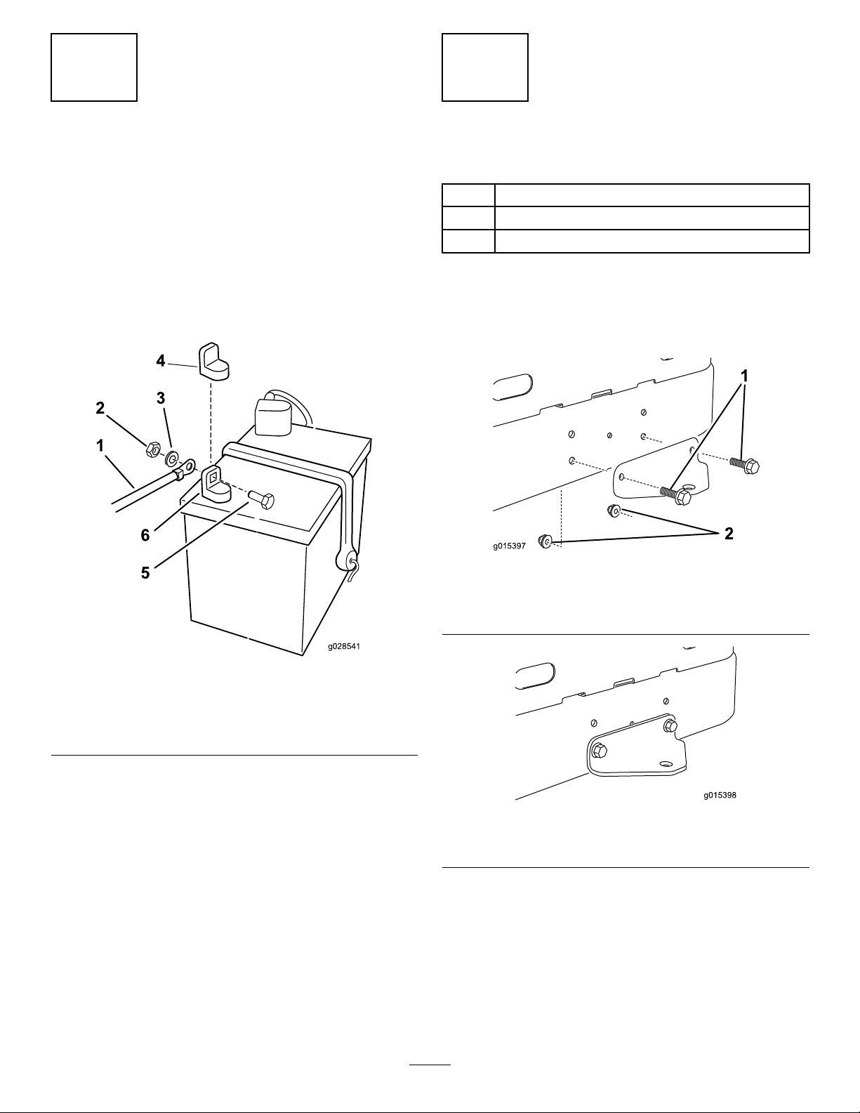
ConnectingtheBattery
NoPartsRequired
Procedure
1.Locatethebatteryandnegativebatterycable.
2.Removetheplasticcapfromthenegativebatterypost.
3.Removethefastenersonthenegativebatterycable,
andusethemtosecurethenegativebatterycableto
thenegativebatterypost(Figure1).
InstallingtheRearHitch
Partsneededforthisprocedure:
1Rearhitch
2
Bolt(5/16x2-1/2inches)
2
Locknut(5/16inch)
Procedure
InstallthebrackettotheframeasshowninFigure2and
Figure3.
Figure2
Beforeassembly
1.Bolts2.Locknuts
Figure1
1.Negativebatterycable4.Negativebatterypostcap
2.Nut5.Bolt
3.Washer6.Negativebatterypost
Figure3
Afterassembly
2
Page 3
3
g028542
A
B
C D
E
F
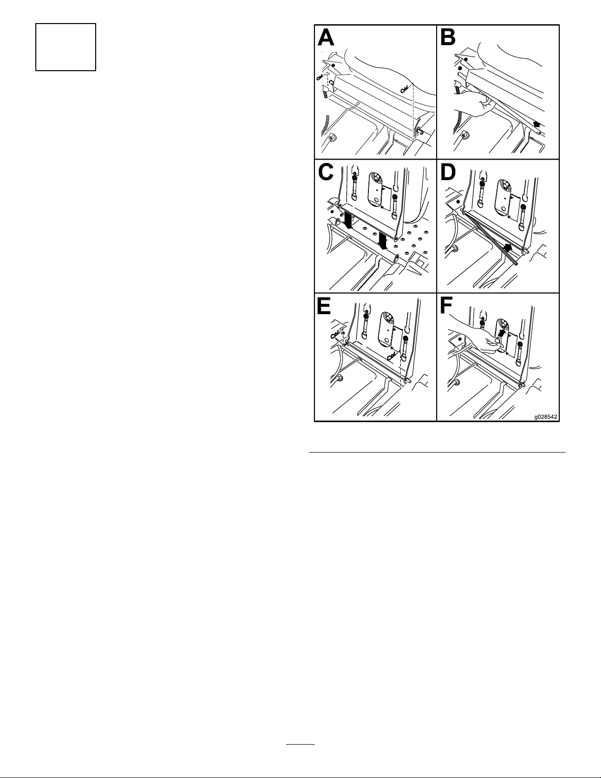
SettinguptheMotion-control
LeversandtheSeat
NoPartsRequired
Procedure
1.Locatethemotion-controlleversattached,butfolded
downonthemachine.
2.Removetheupperbolt(3/8x1inch)andwasher;
loosenthelowerbolt(3/8x1inch).
3.Raisethemotioncontrolleverstotheuprightposition.
4.Aligntheholesinthemotion-controlleverwiththe
holesinthecontrol-armshaft,andinstallthebolt
andwasherremovedpreviously.Repeatthisforboth
controlslevers.
Note:Handtightenallfasteners.
5.Setuptheseatasfollows(Figure4):
Figure4
A.Withthemotioncontrolleversintheoutward,
neutrallockposition,removethehairpincotter
pinsontheseatrodsecuringtheseattothe
machine.
B.Slidetheseatrodoutfromthebracketsandseat
frame.
C.Rotatetheseat180degreesandinstallitintothe
bracketyouremoveditfrom,usingtherodand
hairpincotterpinsremovedpreviously.
D.Connecttheinterlockswitchcabletotheseat.
E.Lowertheseatintotheoperatingposition.
6.Movethecontrolleversbacktothecenterposition
(neutral).
7.Verifythemotioncontrolleversareproperlyaligned.
Adjustasnecessary.Tightenallfasteners.
3
Page 4

4
13
14
15
g028588
InstallingtheRollOver
ProtectionSystem(ROPS)
Partsneededforthisprocedure:
1Rollbar
2Rollbarsupport
2
Reinforcingbracket
4
ROPSplates
10
Bolt(1/2x3–1/2inches)
2
Bolt(1/2x4–1/2inches)
8
Hexlocknut(1/2inch)
8
Flatwasher(1/2inch)
4Thrustwasher
10
Flangelocknut(1/2inch)
2
Bolt(5/16x3–3/4inches)
2
Flangelocknut(5/16inch,maybepre-installed)
2
Flatwasher(5/16inch)
InstallingtheRollbarSupports
Completethefollowingstepsforbothleftandrightrollbar
supports.
1.Locatethefactoryinstalledbraceattachedtotheframe
betweentheengineandtherearwheel(seeFigure5
andFigure6).
Note:Ifpreferred,therearwheelsmayberemoved
foreasieraccesstothebrace.
Figure6
1.Bolt(1/2x3–1/2inches)
(2)
2.Thrushwasher(4)10.Reinforcingbracket(2)
3.Rollbarsupport
4.Cutoutfacestherear12.Bolt(5/16x3–3/4inch)(2)
5.Brace,existing
6.Bolt(1/2x1–1/4inch)and
locknut(1/2inch),existing
7.Seatbeltassembly,
existing
8.Hexlocknut(1/2inch)(2)
9.Flangelocknut(1/2inch)
(2)
11.Bolt(1/2x4–1/2inch)(2)
13.Flatwasher(5/16inch)(2)
14.Flangelocknut(5/16inch)
(2)
15.Engineguard
2.Loosenthelocknutthatsecuresthebracetotheframe.
Stopwhenthebraceswingsfreely(Figure6).
3.Attachtherollbarsupporttotheframeandthebrace
totherollbarsupportasshowninFigure6.Leave
theboltslooseenoughthatthepartsarefreetoshift
around.
Figure5
Locationofthebraces
Note:Ensurethatthecutoutatthetopofthesupport
tubefacestherearofthemachine.
Note:Notetheorientationofthereinforcingbracket.
4.Attachtherollbarsupporttotheengineguardas
showninFigure6.
AttachingtheROPSPlates
AssembletheROPSplatestotherollbarasshowninFigure
7.Leavetheboltslooseenoughthatthepartsarefreeto
shiftaround.
Note:Ensurethatthelocknutsareontheinsideofthe
supporttube.
4
Page 5

g028544
1 2 3
2 4 5
1 2
3
2 1
4
g028545
MakingFinalAdjustments
1.Tightenthefastenersintheorderspeciedinthe
followingtable.Figure6,Figure7,andFigure8will
helpidentifytheparts.
Figure7
1.Flangelocknut(4)4.Flatwasher(4)
2.ROPSplates(4)5.Bolt(1/2x3–1/2inches)
(4)
3.Rollbar
InstallingtheRollbar
1.Lifttherollbarwiththecutoutsinendsofthetube
facingupandaligntheholeswiththerollbarsupports.
Note:Asecondpersontoperformthenextstepwill
behelpful.
2.Attachtherollbartotherollbarsupportsasshownin
Figure8.Leavetheboltsloose.
Sequence
1Fourboltsoneach
2Twoboltsoneach
3
4
DescriptionTorque
sideattachingthe
pivotbracketsto
therollbarand
rollbarsupport.
sideattachingthe
rollbarsupportto
theframeandthe
rollbarsupportto
thebrace.
Oneboltoneach
sideattaching
thebracestothe
machineframe.
Oneboltoneach
sideattachingthe
rollbartotheengine
guard.
400±40in-lbs
(45±.4N-m)
300±30in-lbs
(34±3N-m)
75±8ft-lbs
(102±11N-m)
60to80in-lbs.
(7to9N-m)
Note:Donotexceedtorquespecications.Doingso
maycausestructuraldamagetotheROPSortheframe
ofthemachine.
1.Bolt(1/2x3–1/2inches)
2.Flatwasher(4)
Figure8
(4)
3.Flangelocknut(4)
4.Rollbar
5
Page 6

5
CheckingtheMower
Adjustment
NoPartsRequired
Procedure
Adjusttheside-to-sidelevelandthefront-to-rearbladeslope.
UsetherelevantproceduresintheOperator'sManualtoverify
thatthedeckislevel,andmakeanyadjustmentsasnecessary.
RefertotheOperator'sManualformoreinformation.
6
CompletingtheSetup
Partsneededforthisprocedure:
1Ignitionkey
1
Operator'sManual
1
EngineOperator'sManual
Procedure
CheckingtheTirePressure
Checkthefrontandreartiresforproperination;referto
CheckingtheTirePressureintheOperator'sManualforthe
recommendedinationpressure.
CheckingtheSide-DischargeChute
Removethepackingrestraintholdingthesidedischargechute
upandlowerthechuteintoplace.
CheckingtheEngine-OilLevel
Beforeyoustarttheengineandusethemachine,checkthe
oillevelintheenginecrankcase;refertoCheckingtheOil
LevelintheOperator'sManual.
Keepallthefollowingitemswiththemachine:
•Ignitionkey
•Operator'sManual
•EngineOperator'sManual
6
Page 7

Notes:
7
Page 8

 Loading...