

Page 1

FormNo.3372-551RevA
TITANZX4820Zero-Turn-Radius
RidingMower
ModelNo.74845—SerialNo.312000001andUp
ToregisteryourproductordownloadanOperator'sManualorPartsCatalogatnocharge,gotowww.T oro.com.OriginalInstructions(EN)
Page 2
Thismachineisaride-on,rotary-bladelawnmower
1
G015032
intendedtobeusedbyhomeownersinresidential
applications.Itisprimarilydesignedforcuttinggrass
onwell-maintainedlawns.Itisnotdesignedforcutting
brush,mowinggrassandothergrowthalongside
highways,orforagriculturaluses.
Introduction
Readthisinformationcarefullytolearnhowtooperate
andmaintainyourproductproperlyandtoavoidinjury
andproductdamage.Youareresponsibleforoperating
theproductproperlyandsafely.
WARNING
CALIFORNIA
Proposition65Warning
Thisengineexhaustfromthisproduct
containschemicalsknowntotheStateof
Californiatocausecancer,birthdefects,
orotherreproductiveharm.
Important:Thisengineisnotequippedwitha
sparkarrestermufer.ItisaviolationofCalifornia
PublicResourceCodeSection4442touseoroperate
theengineonanyforest-covered,brush-coverd,or
grasss-coveredland.Otherstatesorfederalareas
mayhavesimilarlaws.
ThissparkignitionsystemcomplieswithCanadian
ICES-002
WARNING
Removingstandardoriginalequipmentpartsand
accessoriesmayalterthewarranty,traction,and
safetyofthemachine.FailuretouseoriginalT oro
partscouldcauseseriousinjuryordeath.Making
unauthorizedchangestotheengine,fuelorventing
system,mayviolateEPAandCARBregulations.
YoumaycontactTorodirectlyatwww .Toro.comfor
productandaccessoryinformation,helpndingadealer,
ortoregisteryourproduct.
Wheneveryouneedservice,genuineToroparts,
oradditionalinformation,contactanAuthorized
ServiceDealerorToroCustomerServiceandhave
themodelandserialnumbersofyourproductready.
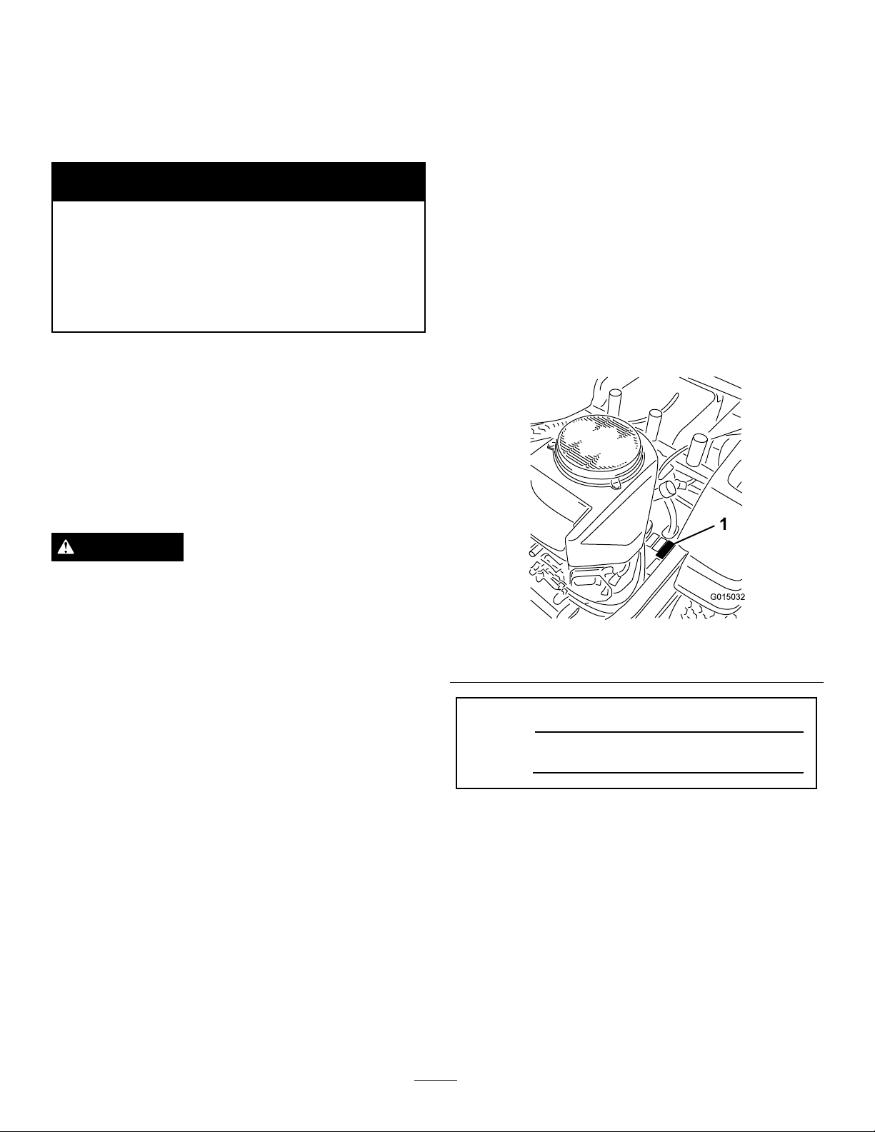
Figure1identiesthelocationofthemodelandserial
numbersontheproduct.Writethenumbersinthe
spaceprovided.
Figure1
1.Modelandserialnumberlocation
Replaceallpartsincluding,butnotlimitedto,tires,
belts,blades,andfuelsystemcomponentswith
originalT oroparts.
Theenclosed
Engine Owner's Man ual
issupplied
forinformationregardingtheUSEnvironmental
ProtectionAgency(EPA)andtheCalifornia
EmissionControlRegulationofemissionsystems,
maintenance,andwarranty.Replacementsmaybe
orderedthroughtheenginemanufacturer.
Formodelswithstatedenginehorsepower,thegross
horsepoweroftheenginewaslaboratorytestedbythe
enginemanufacturerinaccordancewithSAEJ1995and
ratedtoJ2723.
©2012—TheT oro®Company
8111LyndaleAvenueSouth
Bloomington,MN55420
ModelNo.
SerialNo.
Contactusatwww.Toro.com.
2
PrintedintheUSA.
AllRightsReserved
Page 3

Thismanualidentiespotentialhazardsandhassafety
messagesidentiedbythesafetyalertsymbol(Figure2),
whichsignalsahazardthatmaycauseseriousinjury
ordeathifyoudonotfollowtherecommended
precautions.
Figure2
1.Safetyalertsymbol
Thismanualuses2otherwordstohighlightinformation.
Importantcallsattentiontospecialmechanical
informationandNoteemphasizesgeneralinformation
worthyofspecialattention.
Contents
Introduction.................................................................2
Safety...........................................................................4
SafeOperatingPractices.......................................4
ToroRidingMowerSafety....................................6
SlopeIndicator.....................................................7
SafetyandInstructionalDecals.............................8
Setup.........................................................................13
1ConnectingtheBattery....................................13
2CheckingtheMowerAdjustment.....................13
3CompletingtheSetup......................................14
ProductOverview......................................................15
Controls.............................................................16
Operation...................................................................17
ThinkSafetyFirst...............................................17
UsingtheRolloverProtectionSystem
(ROPS)..........................................................18
AddingFuel.......................................................19
CheckingtheEngineOilLevel............................20
OperatingtheParkingBrake...............................20
OperatingtheThrottle.......................................21
OperatingtheChoke..........................................21
OperatingtheIgnitionSwitch.............................21
StartingandStoppingtheEngine........................22
OperatingtheMowerBladeControlSwitch
(PTO)............................................................23
TheSafetyInterlockSystem................................23
DrivingForwardorBackward.............................24
StoppingtheMachine.........................................25
AdjustingtheHeightofCut................................25
AdjustingtheAnti-ScalpRollers.........................26
PositioningtheSeat............................................27
AdjustingtheMotionControlLevers..................27
PushingtheMachinebyHand.............................28
UsingtheSideDischarge....................................28
OperatingTips...................................................28
Maintenance...............................................................30
RecommendedMaintenanceSchedule(s)................30
PremaintenanceProcedures....................................32
RaisingtheSeat..................................................32
Lubrication.............................................................32
GreasingtheBearings.........................................32
EngineMaintenance...............................................33
ServicingtheAirCleaner....................................33
ServicingtheEngineOil.....................................33
ServicingtheSparkPlug.....................................35
CleaningtheCoolingSystem...............................36
FuelSystemMaintenance.......................................37
ReplacingtheFuelFilter.....................................37
ElectricalSystemMaintenance................................38
ServicingtheBattery...........................................38
ServicingtheFuses.............................................39
DriveSystemMaintenance.....................................40
CheckingtheTirePressure.................................40
HydraulicSystemMaintenance...............................41
CheckingtheHydraulicOilLevel........................41
ChangingtheHydraulicSystemFilterand
Oil..................................................................41
MowerDeckMaintenance......................................43
ServicingtheCuttingBlades...............................43
MowerDeckLeveling.........................................45
InspectingtheBelts............................................47
ReplacingtheMowerBelt...................................47
RemovingtheMowerDeck................................48
InstallingtheMowerDeck..................................49
ReplacingtheGrassDeector.............................49
Cleaning.................................................................50
WashingtheUndersideoftheMower..................50
WasteDisposal...................................................51
Storage.......................................................................51
CleaningandStorage..........................................51
Troubleshooting.........................................................53
Schematics.................................................................55
3
Page 4

Safety
Improperuseormaintenancebytheoperatoror
ownercanresultininjury.Toreducethepotential
forinjury,complywiththesesafetyinstructions
andalwayspayattentiontothesafetyalert
symbol,whichmeansCAUTION,WARNING,or
DANGER-"personalsafetyinstruction."Failureto
complywiththeinstructionmayresultinpersonal
injuryordeath.
•Neverleavearunningmachineunattended.Always
turnoffblades,setparkingbrake,stopengine,and
removekeybeforedismounting.
•Turnoffbladeswhennotmowing.Stoptheengine,
waitforallpartstocometoacompletestop
andremovethekeybeforecleaningthemachine,
removingthegrasscatcheroruncloggingthe
dischargechute.
•Operatethemachineonlyindaylightorgood
articiallight.
SafeOperatingPractices
Thisproductiscapableofamputatinghandsand
feetandthrowingobjects.Alwaysfollowallsafety
instructionstoavoidseriousinjuryordeath.
ThefollowingsafetyinstructionsarebasedonANSI
standardB71.1-2003.Safetyinformationinaddition
totheinstructionsfoundintheANSIstandardbelow
canbefoundinToroRidingMowerSafetyattheend
ofthissection.
GeneralOperation
•Read,understand,andfollowallinstructionsin
theoperator'smanualandonthemachinebefore
starting.
•Donotplacehandsorfeetnearrotatingpartsor
underthemachine.Keepclearofthedischarge
openingatalltimes.
•Allowonlyresponsibleadultswhoarefamiliarwith
theinstructionstooperatethemachine.
•Donotoperatethemachinewhileunderthe
inuenceofalcoholordrugs.
•Watchfortrafcwhenoperatingnearorcrossing
roadways.
•Useextracarewhenloadingorunloadingthe
machineintoatrailerortruck.
•Alwaysweareyeprotectionwhenoperatingthe
mower.
•Dataindicatesthatoperators,age60yearsand
above,areinvolvedinalargepercentageofriding
mower-relatedinjuries.Operatorsshouldevaluate
theirabilitytooperatetheridingmowersafely
enoughtoprotectthemselvesandothersfrom
seriousinjury.
•Alwaysfollowtherecommendationsforany
applicationofcounterweights.
•Lightningcancausesevereinjuryordeath.If
lightningisseenorthunderisheardinthearea,do
notoperatethemachine;seekshelter.
•Cleartheareaofobjectssuchasrocks,toys,wire,etc.,
whichcouldbepickedupandthrownbytheblade.
•Besuretheareaisclearofotherpeoplebefore
mowing.Stopthemachineifanyoneentersthearea.
•Nevercarrypassengers.
•Donotmowinreverseunlessabsolutelynecessary.
Alwayslookdownandbehindbeforeandwhile
backingup.
•Beawareofthemowerdischargedirectionanddo
notpointitatanyone.Avoiddischargingmaterial
againstawallorobstruction.Materialmayricochet
backtowardtheoperator.Stoptheblade(s)when
crossinggravelsurfaces.
•Donotoperatethemachinewithoutdeector,
dischargecoverorentiregrasscollectionsystemin
placeandworking.
•Bealert,slowdownandusecautionwhenmaking
turns.Lookbehindandtothesidebeforechanging
directions.
SlopeOperation
Slopesareamajorfactorrelatedtolossofcontroland
tip-overaccidents,whichcanresultinsevereinjuryor
death.Operationonallslopesrequiresextracaution.If
youcannotbackuptheslopeorifyoufeeluneasyonit,
donotmowit.
•Donotmowslopesgreaterthan15degrees.
•Watchforditches,holes,rocks,dips,andrisesthat
changetheoperatingangle,asroughterraincould
overturnthemachine.
•Choosealowgroundspeedsoyouwillnothaveto
stopwhileoperatingonaslope.
•Donotmowslopeswhengrassiswet.Slippery
conditionsreducetractionandcouldcausesliding
andlossofcontrol.
•Alwayskeepthedrivewheelsengagedwhengoing
downslopes.
•Reducespeedanduseextremecautiononslopes.
4
Page 5

•Donotmakesuddenturnsorrapidspeedchanges.
•Removeormarkobstaclessuchasrocks,treelimbs,
etc.fromthemowingarea.Tallgrasscanhide
obstacles.
•Avoidsuddenstartswhenmowinguphillbecausethe
mowermaytipbackwards.
•Beawarethatlossoftractionmayoccurgoing
downhill.Weighttransfertothefrontwheelsmay
causedrivewheelstoslipandcauselossofbraking
andsteering.
•Alwaysavoidsuddenstartingorstoppingonaslope.
Iftireslosetraction,stopthemachine,disengagethe
bladesandproceedslowlyofftheslope.
•Useextremecarewithgrasscatchersorother
attachments.Thesecanchangethestabilityofthe
machineandcauselossofcontrol.
•Donottrytostabilizethemachinebyputtingyour
footontheground.
•Keepchildrenoutofthemowingareaandunderthe
watchfulcareofanotherresponsibleadult,notthe
operator.
•Bealertandturnthemachineoffifchildrenenter
thearea.
•Beforeandwhilebackingorchangingdirection,look
behind,down,andside-to-sideforsmallchildren.
•Nevercarrychildren,evenwiththebladesoff.They
mayfalloffandbeseriouslyinjuredorinterferewith
safemachineoperation.
•Childrenwhohavebeengivenridesinthepastmay
suddenlyappearinthemowingareaforanotherride
andberunoverorbackedoverbythemower.
•Neverallowchildrentooperatethemachine.
•Useextracarewhenapproachingblindcorners,
shrubs,trees,theendofafenceorotherobjectsthat
mayobscurevision.
•Donotmowneardrop-offs,ditches,steepbanks
orwater.Wheelsdroppingoveredgescancause
rollovers,whichmayresultinseriousinjury,death
ordrowning.
•Useawalkbehindmowerand/orahandtrimmer
neardrop-offs,ditches,steepbanksorwater.
UsingtheRolloverProtectionSystem
(ROPS)
•Keeptherollbarinthefullyraisedandlocked
positionandusetheseatbeltwhenoperatingthe
machine.
•Becertainthattheseatbeltcanbereleasedquickly
intheeventofanemergency.
•Beawarethereisnorolloverprotectionwhenthe
rollbarisdown.
•Checktheareatobemowedandneverfoldthe
ROPSinareaswherethereareslopes,dropoffsor
water.
•Lowertherollbaronlywhenabsolutelynecessary.
Donotweartheseatbeltwiththerollbarfolded
down.
•Checkcarefullyforoverheadclearances(i.e.
branches,doorways,electricalwires)beforedriving
underanyobjectsanddonotcontactthem.
Children
Tragicaccidentscanoccuriftheoperatorisnotalertto
thepresenceofchildren.Childrenareoftenattractedto
themachineandthemowingactivity.Neverassumethat
childrenwillremainwhereyoulastsawthem.
Towing
Ahitchkitisavailableforthismachineandcanbe
obtainedbycontactinganAuthorizedToroDealer.
Donottowwithoutrstinstallingthismanufacturer
approvedhitch.Thefollowingguidelinesapplywhen
towingwiththeapprovedhitchkitinstalled.
•Towonlywithamachinethathasahitchdesigned
fortowing.Donotattachtowedequipmentexcept
atthehitchpoint.
•Followthemanufacturer'srecommendationfor
weightlimitsfortowedequipmentandtowingon
slopes.
•Neverallowchildrenorothersinorontowed
equipment.
•Onslopes,theweightofthetowedequipmentmay
causelossoftractionandlossofcontrol.
•Travelslowlyandallowextradistancetostop.
Service
SafeHandlingofGasoline:
Toavoidpersonalinjuryorpropertydamage,useextra
carewhenhandlinggasolineandotherfuels.Theyare
ammableandthevaporsareexplosive.
•Extinguishallcigarettes,cigars,pipesandother
sourcesofignition.
•Useonlyanapprovedcontainer.
•Neverremovethegascaporaddfuelwhenthe
engineisrunning.Allowtheenginetocoolbefore
refueling.
5
Page 6

•Neverrefuelthemachineindoors.
•Neverstorethemachineorfuelcontainerinside
wherethereisanopename,suchasnearawater
heaterorfurnace.
•Neverllcontainersinsideavehicleoronatruckor
trailerwithaplasticliner.Alwaysplacecontainerson
thegroundawayfromyourvehiclebeforelling.
•Removegas-poweredequipmentfromthetruck
ortrailerandrefuelitontheground.Ifthisisnot
possible,thenrefuelsuchequipmentwithaportable
container,ratherthanfromagasolinedispenser
nozzle.
•Keepthenozzleincontactwiththerimofthefuel
tankorcontaineropeningatalltimesuntilthefueling
iscomplete.Donotuseanozzlelock-opendevice.
•Iffuelisspilledonclothing,changeclothing
immediately.
•Neveroverllthefueltank.Replacegascapand
tightensecurely .
GeneralService:
•Maintainorreplacesafetyandinstructiondecalsas
necessary.
•UseonlygenuineTororeplacementpartstoensure
thatoriginalstandardsaremaintained.
ToroRidingMowerSafety
Thefollowinglistcontainssafetyinformationspecicto
Toroproductsorothersafetyinformationthatyoumust
knowthatmaynotbeincludedintheANSIstandards.
•Stoptheengine,movethemotioncontrolleversto
neutralandoutwardtotheparkposition,disengage
thebladecontrolswitch,removekeybeforeand
disconnectsparkplugwire(s)performinganyservice,
repairs,maintenanceoradjustments.
•Keephands,feet,hair,andlooseclothingawayfrom
attachmentdischargearea,undersideofmowerand
anymovingpartswhileengineisrunning.
•Donottouchequipmentorattachmentpartswhich
maybehotfromoperation.Allowtocoolbefore
attemptingtomaintain,adjustorservice.
•Neveroperateamachineinsideaclosedarea.Engine
exhaustcontainscarbonmonoxide,whichisan
odorless,deadlypoisonthatcankillyou.
•Keepnutsandboltstight,especiallytheblade
attachmentbolts.Keepequipmentingood
condition.
•Nevertamperwithsafetydevices.Checktheir
properoperationregularly.
•Keepthemachinefreeofgrass,leaves,orother
debrisbuild-up.Cleanupoilorfuelspillagefuel
soakeddebris.Allowthemachinetocoolbefore
storing.
•Stopandinspecttheequipmentifyoustrikean
object.Repair,ifnecessary,beforerestarting.
•Nevermakeanyadjustmentsorrepairswiththe
enginerunning.
•Grasscatchercomponentsaresubjecttowear,
damageanddeterioration,whichcouldexpose
movingpartsorallowobjectstobethrown.
Frequentlycheckcomponentsandreplacewith
manufacturers'recommendedparts,whennecessary.
•Batteryacidispoisonousandcancauseburns.Avoid
contactwithskin,eyes,andclothing.Protectyour
face,eyes,andclothingwhenworkingwithabattery.
•Batterygasescanexplode.Keepcigarettes,sparks
andamesawayfrombattery.
•UseonlyToroapprovedattachments.W arrantymay
bevoidedifusedwithunapprovedattachments.
•Ifloadingthemachineontoatrailerortruck,usea
single,full-widthramponly.Therampangleshould
notexceed15degrees.
•Mowerbladesaresharpandcancut.Wrapthe
blade(s)orweargloves,anduseextracautionwhen
servicingthem.
•Checkforproperbrakeoperationfrequently.Adjust
andserviceasrequired.
6
Page 7
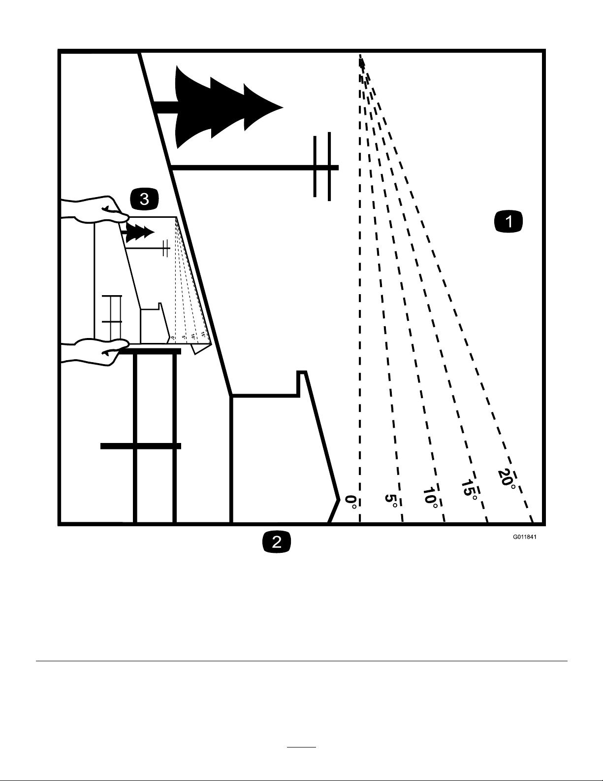
SlopeIndicator
G011841
Figure3
Thispagemaybecopiedforpersonaluse.
1.Themaximumslopeyoucansafelyoperatethemachineonis15degrees.Usetheslopecharttodeterminethedegreeofslope
ofhillsbeforeoperating.Donotoperatethismachineonaslopegreaterthan15degrees.Foldalongtheappropriateline
tomatchtherecommendedslope.
2.Alignthisedgewithaverticalsurface,atree,building,fencepole,etc.
3.Exampleofhowtocompareslopewithfoldededge.
7
Page 8
SafetyandInstructional
Decals
Safetydecalsandinstructionsareeasilyvisibletotheoperatorandarelocatednearanyareaof
potentialdanger.Replaceanydecalthatisdamagedorlost.
93-7009
1.Warning—don'toperatethemowerwiththedeectorupor
removed;keepthedeectorinplace.
2.Cutting/dismembermenthazardofhandorfoot,mower
blade—stayawayfrommovingparts.
112-9840
99-8936
1.Machinespeed4.Neutral
2.Fast5.Reverse
3.Slow
1.ReadtheOperator's
Manual.
2.Heightofcut
3.Removetheignitionkey
andreadtheinstructions
beforeservicingor
performingmaintenance.
114-1606
1.Entanglementhazard,belt—keepallguardsinplace.
110-6691
1.Thrownobjecthazard—keepbystandersasafedistance
fromthemachine.
2.Thrownobjecthazard,mower—donotoperatewithoutthe
deector,dischargecover,orgrasscollectionsystemin
place.
3.Cutting/dismembermentofhandorfoot—stayawayfrom
movingparts.
115-9625
1.Parking
brake—disengaged
2.Parkingbrake—engaged
8
Page 9
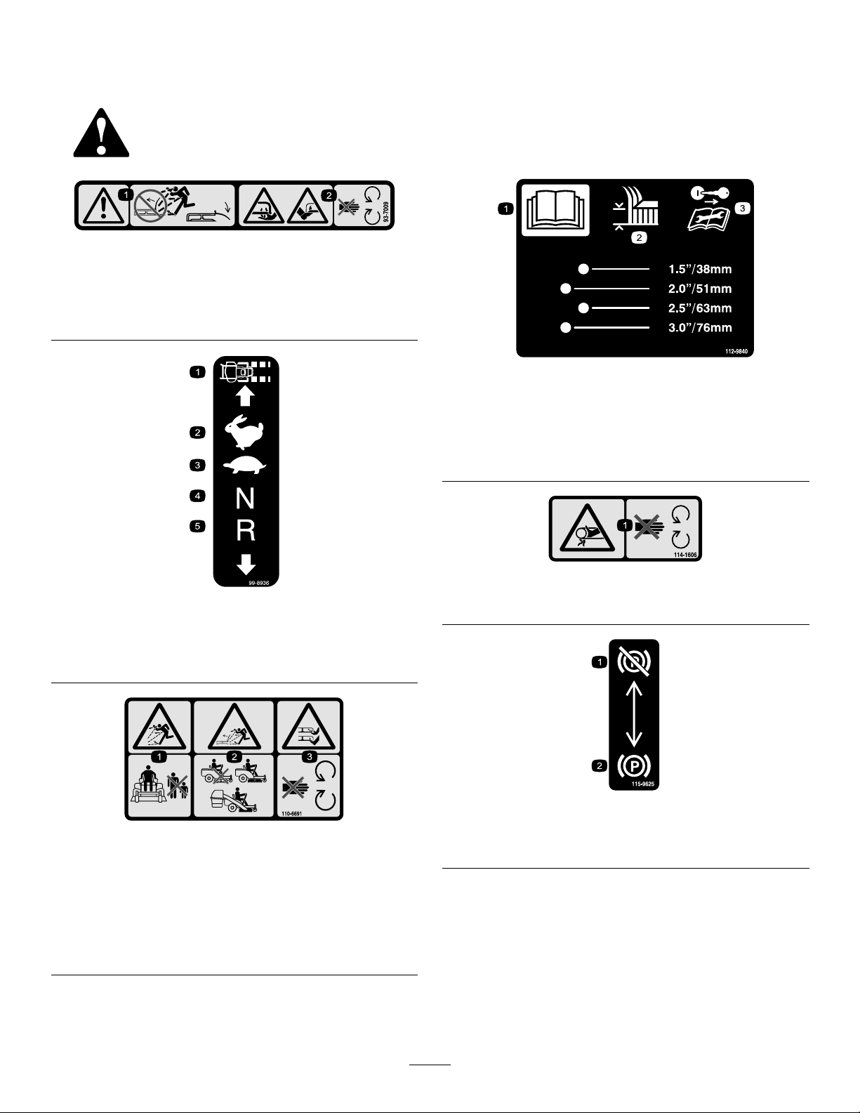
117-1158
1.Bypassleverpositionfor
operatingthemachine
2.Bypassleverpositionfor
pushingthemachine
115-9632
1.Powertake-off(PTO),
Bladecontrolswitchon
somemodels
2.Bladecontrolswitch—On6.Continuousvariable
3.Bladecontrolswitch—Off7.Slow
4.Choke
5.Fast
setting
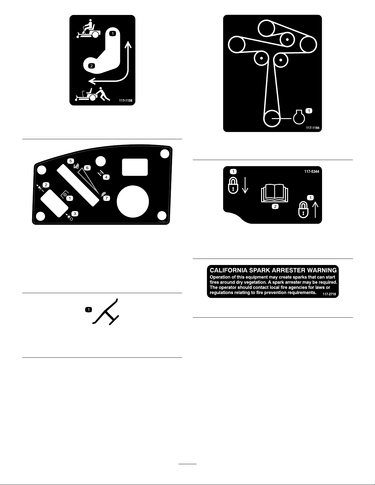
117-1194
1.Engine
117-5344
1.Lock
2.ReadtheOperator'sManual
Manufacturer'sMark
1.Indicatesthebladeisidentiedasapartfromtheoriginal
machinemanufacturer.
117–2718
9
Page 10
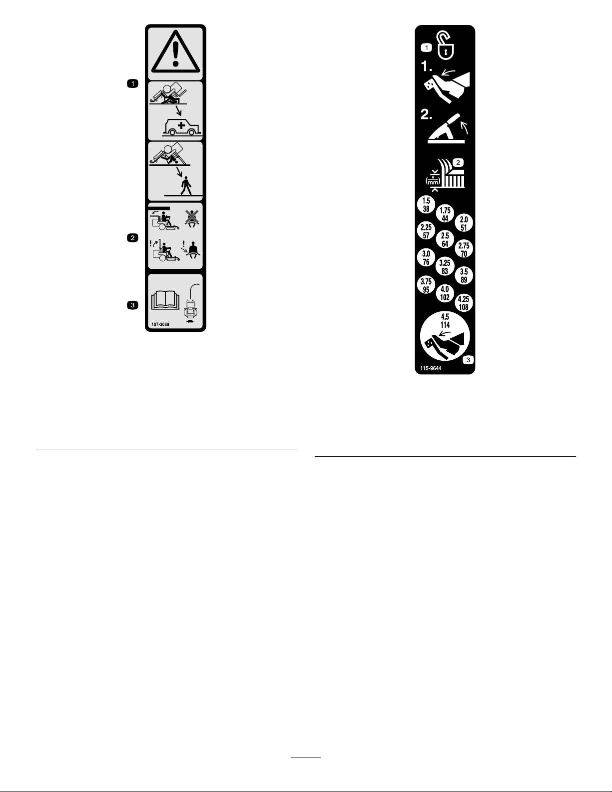
107-3069
1.Warning–thereisnorolloverprotectionwhentherollbaris
down.
2.Toavoidinjuryordeathfromarolloveraccident,keepthe
rollbarinthefullyraisedandlockedpositionandwear
theseatbelt.Lowertherollbaronlywhenabsolutely
necessary;donotwearthetheseatbeltwhentherollbaris
down.
3.ReadtheOperator'sManual;driveslowlyandcarefully.
115-9644
1.Pressthepedalandlifttheheightofcutlevertounlockthe
deckposition.
2.Heightofcut
3.Pressthepedaltomovethedecktothetransportposition
10
Page 11

BatterySymbols
Someorallofthesesymbolsareonyourbattery
1.Explosionhazard
2.Nore,opename,or
smoking.
3.Causticliquid/chemical
burnhazard
4.Weareyeprotection9.Flusheyesimmediately
5.ReadtheOperator's
Manual.
6.Keepbystandersasafe
7.Weareyeprotection;
8.Batteryacidcancause
10.Containslead;donot
distancefromthebattery.
explosivegasescan
causeblindnessandother
injuries
blindnessorsevereburns.
withwaterandgetmedical
helpfast.
discard.
115-9630
1.ReadtheOperator'sManualbeforeperformingany
maintenance.
2.Checktheengineoilevery8hours5.Checkthecasterwheeltirepressureevery25hours
3.Checkthedrivewheeltirepressureevery25hours
4.Checkthehydraulicoilevery25hours
6.Lubricatethecasterwheelevery25hours
11
Page 12

120-5466
1.Warning—readtheOperator'sManual.5.Lossoftraction/controlhazard,slopes—lossoftraction/control
2.Warning—readtheinstructionsbeforeservicingorperforming
maintenance;movethemotioncontrolleverstothepark
(brake)position,removetheignitionkeyanddisconnectthe
sparkplugwire.
3.Cutting/dismembermenthazard,mowerblade;entanglement
hazard,belt—stayawayfrommovingparts,keepallguards
andshieldsinplace.
4.Warning—donotusesplitramps,useafullrampswhen
transportingmachine.
onaslope,disengagethebladecontrolswitch(PTO),
proceedofftheslopeslowly.
6.Crushing/dismembermenthazardofbystanders,
reversing—donotcarrypassengers,lookbehindanddown
whenreversing.
7.Thrownobjecthazard—keepbystandersasafedistancefrom
themachine,pickupdebrisbeforeoperating,keepdeector
inplace.
8.Tippinghazard—donotturnathighspeeds,donotoperate
neardrop-offsonslopesgreaterthan15degrees,donotmow
slopesgreaterthan15degrees,avoidsuddenandsharp
turnswhileonslopes.
1.Fuel2.Full
119-8983
3.Half
4.Empty
12
Page 13
Setup
G010257
1
2
3
5
4
LooseParts
Usethechartbelowtoverifythatallpartshavebeenshipped.
ProcedureDescription
1
2
3
Nopartsrequired
Nopartsrequired
IgnitionKey1
Hosecoupling1
Operator'sManual
EngineOperator'sManual
OperatorTrainingMaterial
1
ConnectingtheBattery
NoPartsRequired
Procedure
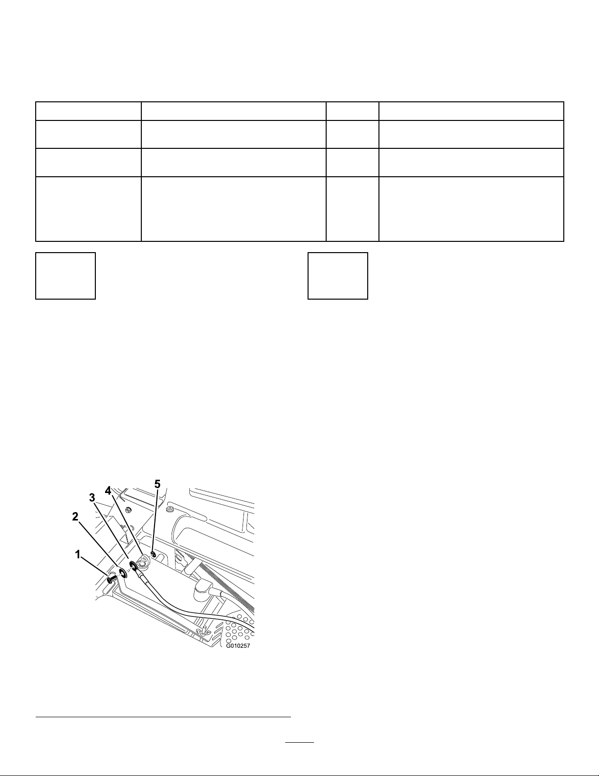
1.Locatethebatteryandnegativebatterycableinthe
centerofthemachine.
2.Removetheblackplasticcapfromthenegative
batterypost.Removethefastenersfromthenegative
batterycableandusethemtosecurethenegative
batterycabletothenegativebatterypost(
Figure4).
Qty.
–
–
1
1
1
Connectthebattery .
Checkthemoweradjustment.
CompletetheSetup.
Use
2
CheckingtheMower
Adjustment
NoPartsRequired
Procedure
Adjusttheside-to-sidelevelandthefront-to-rearblade
slope.UsetherelevantproceduresintheOperator's
Manualtoverifythedeckislevelandmakeany
adjustmentsasnecessary.RefertotheOperator'sManual
formoreinformation.
1.Bolt4.Negativebatterypost
2.Washer5.Nut
3.Negativebatterycable
Figure4
13
Page 14

ReviewtheRemainingParts
Keepallthefollowingitemswiththemachine:
3
•IgnitionKey
CompletingtheSetup
Partsneededforthisprocedure:
1IgnitionKey
1Hosecoupling
1
Operator'sManual
1
EngineOperator'sManual
1
OperatorTrainingMaterial
Procedure
SettingUptheMotionControlLevers
Ifneeded,removetheupperbolt,washerandnutand
raisethemotioncontrolleverstotheuprightposition.
Securethemotioncontrollevers.RefertoAdjustingthe
MotionControlLeversintheOperationSection.
RaisingtheROPS
RaisetheROPSintotheuprightpositionandsecureit
inplace.RefertoUsingtheRolloverProtectionSystem
(ROPS)intheOperationSection.
•Hosecoupling
•Operator'sManual
•EngineOperator'sManual
•ViewtheOperatortrainingmaterial.
CheckingtheTirePressure
Checkthefrontandreartiresforproperination.Refer
toCheckingtheTirePressureintheOperator'sManual
fortherecommendedinationpressure.
CheckingtheSideDischargeChute
Removethepackingrestraintholdingthesidedischarge
chuteupandlowerthechuteintoplace.
CheckingtheEngineOilLevel
Beforeyoustarttheengineandusethemachine,check
theoillevelintheenginecrankcase;refertoChecking
theOilLevelintheOperator'sManual.
CheckingtheHydraulicOilLevel
Beforeyoustarttheengineandusethemachine,check
thehydraulicoillevelinthereservoirbehindtheseat;
refertoCheckingtheOilLevelintheOperator'sManual.
CheckingtheMowerAdjustment
Themowerdeckwasleveledatthefactory.Ifthemower
isnotcuttinglevel,adjusttheside-to-sidelevelandthe
front-to-rearbladeslope.SeetheOperator'sManual
fortheproperprocedure.
14
Page 15
ProductOverview
G015763
1
2
3
4
5
6
7
8
9
10
G014766
1
2
3
4
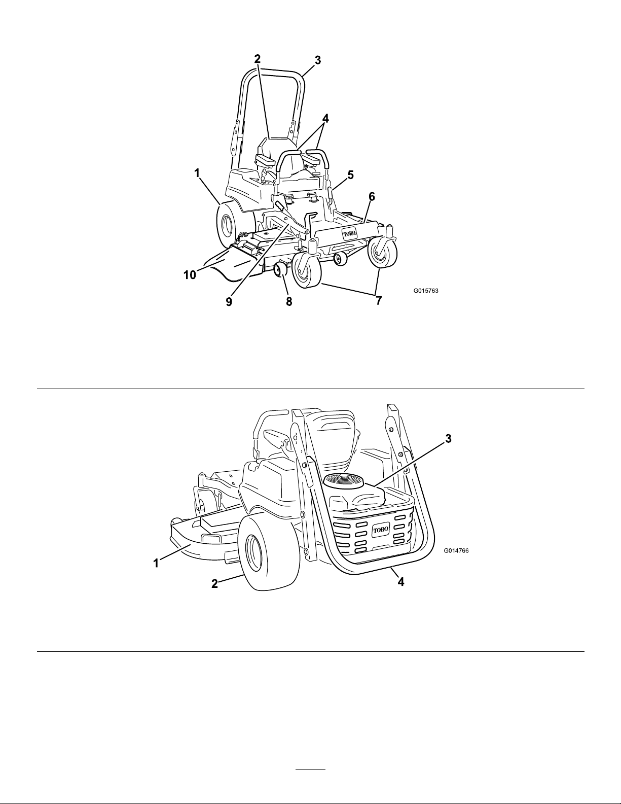
Figure5
1.Drivewheel4.Motioncontrollevers7.Frontcasterwheel
2.Operatorseat
3.Rolloverprotectionsystem
(ROPS)
1.MowerDeck3.Engine
2.Drivewheel
5.Parkingbrake8.Anti-scalproller
6.Footrest
9.Footpedaldeckliftand
height-of-cut
Figure6
4.Rolloverprotectionsystem(ROPS),foldeddown
10.Deector
15
Page 16
Controls
g017722
1
2
3
4
5
G010077
1
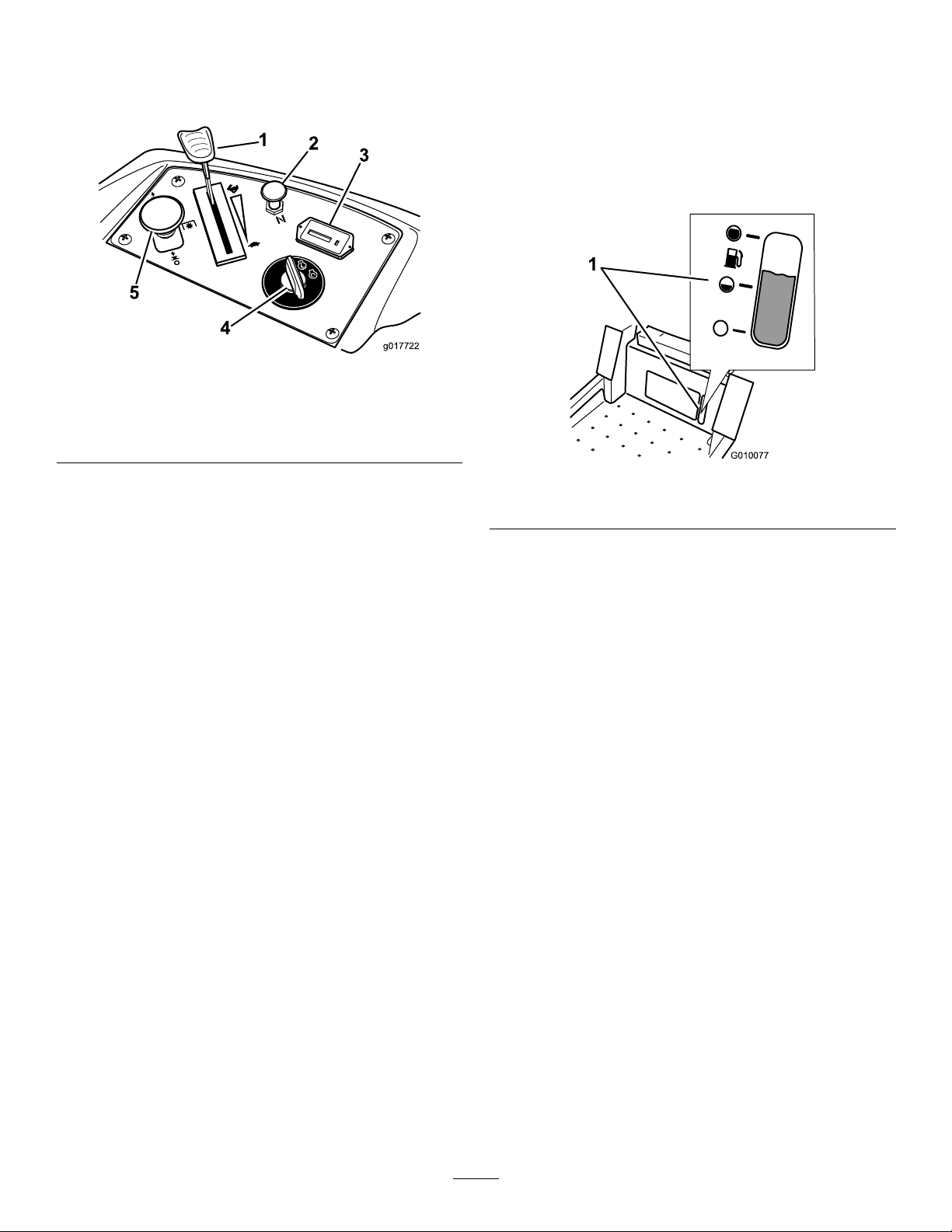
Becomefamiliarwithallthecontrolsbeforeyoustart
theengineandoperatethemachine(Figure7).
Figure7
1.Throttlecontrol4.Ignitionswitch
2.Choke5.Bladecontrolswitch(PTO)
3.Hourmeter
switch(PTO)isengaged.Usethesetimesforscheduling
regularmaintenance(
Figure7).
FuelGauge
Thefuelwindowlocatedbelowtheoperatorposition
canbeusedtoverifythelevelofgasolineinthetank
(Figure8).
Figure8
IgnitionSwitch
Theignitionswitchhasthreepositions:Start,Run
andOff.ThekeywillturntoStartandmovebackto
Runuponrelease.TurningthekeytotheOffposition
willstoptheengine;however,alwaysremovethekey
whenleavingthemachinetopreventtheenginefrom
accidentallystarting(
Figure7).
ThrottleControl
ThethrottlecontrolisvariablebetweenFastandSlow.
Movingthrottleleverforwardwillincreaseenginespeed
andmovingthrottlelevertotherearwilldecreaseengine
speed.Movingthethrottleforwardintothedetentis
fullthrottle(
Figure7).
Choke
Usethechoketostartacoldengine.Pullthechoke
knobuptoengageit.Pushdownonthechokeknob
todisengageit.
1.Fuelgaugewindow
MotionControlLevers
Themotioncontrolleversarespeedsensitivecontrols
ofindependentwheelmotors.Movingaleverforward
orbackwardturnsthewheelonthesamesideforward
orinreverse;wheelspeedisproportionaltotheamount
theleverismoved.Movethecontrolleversoutward
fromthecentertotheneutrallockpositionandexitthe
machine(
Figure5).Alwayspositionthemotioncontrol
leversintotheneutrallockpositionwhenyoustopthe
machineorleaveitunattended.
ParkingBrakeLever
Locatedonleftsideoftheconsole(Figure5).Thebrake
leverengagesaparkingbrakeonthedrivewheels.Pull
theleverupandrearwardtoengagethebrake.Pushthe
leverforwardanddowntodisengagethebrake.
BladeControlSwitch(PowerTake-Off)
Thebladecontrolswitch,representedbyapower
take-off(PTO)symbol,engagesanddisengagespower
tothemowerblades(Figure7).
HourMeter
Thehourmeterrecordsthenumberofhourstheblades
haveoperated.Itoperateswhenthebladecontrol
FootPedalDeckLiftSystem
Thefootpedaldeckliftsystemallowstheoperator
tolowerandraisethedeckfromtheseatedposition.
Theoperatorcanusethefootpedaltoliftthedeck
brieytoavoidobstaclesorlockthedeckinthehighest
height-of-cutortransportposition(Figure5).
16
Page 17

Height-of-CutLever
Theheight-of-cutleverworkswiththefootpedalto
lockthedeckinaspeciccuttingheight.Onlyadjustthe
heightofcutwhilemachineisnotmoving(Figure5).
Operation
Note:Determinetheleftandrightsidesofthe
machinefromthenormaloperatingposition.
Attachments/Accessories
AselectionofToroapprovedattachmentsand
accessoriesareavailableforusewiththemachineto
enhanceandexpanditscapabilities.Contactyour
AuthorizedServiceDealerorDistributororgoto
www.Toro.comforalistofallapprovedattachments
andaccessories.
ThinkSafetyFirst
Pleasecarefullyreadallofthesafetyinstructionsand
decalsinthesafetysection.Knowingthisinformation
couldhelpyou,yourfamily,petsorbystandersavoid
injury.
DANGER
Mowingonwetgrassorsteepslopescancause
slidingandlossofcontrol.
Wheelsdroppingoveredgescancauserollovers,
whichmayresultinseriousinjury,deathor
drowning.
Alossoftractionisalossofsteeringcontrol.
Toavoidlossofcontrolandpossibilityofrollover:
•Donotmowneardrop-offsornearwater.
•Donotmowslopesgreaterthan15degrees.
•Reducespeedanduseextremecautionon
slopes.
•Whenmowingslopes,graduallyworkfrom
lowertohigherareasontheincline.
•Avoidsuddenturnsorrapidspeedchanges.
•Turnup,intoaninclinewhenchanging
directionsonslopes.Turningdowntheslope
reducestraction.
•Attachmentschangethehandling
characteristicsofthemachine.Use
extracautionwhenusingattachmentswiththe
machine.
17
Page 18

G015033
1
2
3
Figure9
G015034
G015035
1
2
3
2
1.SafeZone-usethemachinehere
2.Usewalkbehindmowerand/orhandtrimmerneardrop-offs
andwater.
3.Water
UsingtheRolloverProtection
System(ROPS)
WARNING
Toavoidinjuryordeathfromrollover:keepthe
rollbarinthefullyraisedlockedpositionanduse
theseatbelt.
WARNING
Thereisnorolloverprotectionwhentherollbar
isinthedownposition.
•Lowertherollbaronlywhenabsolutely
necessary.
Figure10
Important:Alwaysusetheseatbeltwiththe
rollbarinthefullyraisedposition.
3.Installthelockingpins.Securethepinsbyinstalling
thehaircotterpin(Figure11).
Figure11
1.HoleinROPS
2.Lockingpin
3.Hairpincotter
•Donotweartheseatbeltwhentherollbaris
inthedownposition.
•Driveslowlyandcarefully.
•Raisetherollbarassoonasclearancepermits.
•Checkcarefullyforoverheadclearances(i.e.
branches,doorways,electricalwires)before
drivingunderanyobjectsanddonotcontact
them.
Important:Lowertherollbaronlywhen
absolutelynecessary.
1.Toraisetherollbar,removethehaircotterpinand
removethelockingpins.
2.Raisetherollbartotheuprightposition(Figure10).
4.Twolowertherollbar,removethehaircotterpin
andremovethelockingpin.(Figure11).
5.Lowertherollbartothedownposition.
6.Usethetwolockingandcotterpinstosecurethe
bar.
18
Page 19

AddingFuel
DANGER
•Forbestresults,useonlyclean,fresh,unleaded
gasolinewithanoctaneratingof87orhigher
((R+M)/2ratingmethod).
•Oxygenatedfuelwithupto10%ethanolor15%
MTBEbyvolumeisacceptable.
•DoNotuseethanolblendsofgasoline(suchasE15
orE85)withmorethan10%ethanolbyvolume.
Performanceproblemsand/orenginedamagemay
resultwhichmaynotbecoveredunderwarranty.
•DoNotusegasolinecontainingmethanol.
•DoNotstorefueleitherinthefueltankorfuel
containersoverthewinterunlessafuelstabilizeris
used.
•DoNotaddoiltogasoline.
DANGER
Incertainconditions,gasolineisextremely
ammableandhighlyexplosive.Areorexplosion
fromgasolinecanburnyouandothersandcan
damageproperty.
•Fillthefueltankoutdoors,inanopenarea,
whentheengineiscold.Wipeupanygasoline
thatspills.
Incertainconditionsduringfueling,static
electricitycanbereleasedcausingasparkwhich
canignitethegasolinevapors.Areorexplosion
fromgasolinecanburnyouandothersandcan
damageproperty.
•Alwaysplacegasolinecontainersontheground
awayfromyourvehiclebeforelling.
•Donotllgasolinecontainersinsideavehicle
oronatruckortrailerbedbecauseinterior
carpetsorplastictruckbedlinersmayinsulate
thecontainerandslowthelossofanystatic
charge.
•Whenpractical,removegas-powered
equipmentfromthetruckortrailerandrefuel
theequipmentwithitswheelsontheground.
•Ifthisisnotpossible,thenrefuelsuch
equipmentonatruckortrailerfromaportable
container,ratherthanfromagasolinedispenser
nozzle.
•Ifagasolinedispensernozzlemustbeused,
keepthenozzleincontactwiththerimofthe
fueltankorcontaineropeningatalltimesuntil
fuelingiscomplete.
•Neverllthefueltankinsideanenclosedtrailer.
•Donotllthefueltankcompletelyfull.Add
gasolinetothefueltankuntilthelevelis1/4to
1/2inch(6to13mm)belowthebottomofthe
llerneck.Thisemptyspaceinthetankallows
gasolinetoexpand.
•Neversmokewhenhandlinggasoline,andstay
awayfromanopenameorwheregasoline
fumesmaybeignitedbyaspark.
•Storegasolineinanapprovedcontainerand
keepitoutofthereachofchildren.Neverbuy
morethana30-daysupplyofgasoline.
•Donotoperatewithoutentireexhaustsystem
inplaceandinproperworkingcondition.
WARNING
Gasolineisharmfulorfatalifswallowed.
Long-termexposuretovaporscancauseserious
injuryandillness.
•Avoidprolongedbreathingofvapors.
•Keepfaceawayfromnozzleandgastankor
conditioneropening .
•Keepgasawayfromeyesandskin.
UsingStabilizer/Conditioner
Useafuelstabilizer/conditionerinthemachineto
providethefollowingbenets:
•Keepsgasolinefreshduringstorageof90daysor
less.Forlongerstorageitisrecommendedthatthe
fueltankbedrained.
•Cleanstheenginewhileitruns
•Eliminatesgum-likevarnishbuildupinthefuel
system,whichcauseshardstarting
Important:Donotusefueladditivescontaining
methanolorethanol.
Addthecorrectamountofgasstabilizer/conditioner
tothegas.
19
Page 20

Note:Afuelstabilizer/conditionerismosteffective
G010077
1
G010475
1
2
4
3
G010078
1
2
whenmixedwithfreshgasoline.Tominimizethe
chanceofvarnishdepositsinthefuelsystem,usefuel
stabilizeratalltimes.
FuelGauge
Usethefuelwindowbelowtheoperatortoverifythe
levelofgasolinebeforellingthetank(Figure12).
Figure12
Figure13
1.Fuelgaugewindow
FillingtheFuelT ank
Makesuretheengineisshutoffandthemotion
controlsareintheparkposition.
Important:DoNotoverllfueltank.Fillthe
fueltanktothebottomofthellerneck.The
emptyspaceinthetankallowsthefueltoexpand.
Overllingmayresultinfuelleakageordamageto
theengineoremissionsystem.
1.Cleanaroundthefueltankcapandremovethecap.
Note:Youcanusethefuelwindowbelowthe
operatingpositionverifythepresenceofgasoline
beforellingthetank(
2.Slowlyaddregular,unleadedgasolineuntilthefuel
reachesthebaseofthellerneck
Figure12).
Figure13.
3.Installthefueltankcapsecurelyandtightenuntilit
“clicks”.Wipeupanygasolinethatmayhavespilled.
CheckingtheEngineOilLevel
Beforeyoustarttheengineandusethemachine,check
theoillevelintheenginecrankcase;refertoChecking
theEngineOilLevel.
OperatingtheParkingBrake
Alwayssettheparkingbrakewhenyoustopthe
machineorleaveitunattended.
SettingtheParkingBrake
Figure14
20
Page 21

ReleasingtheParkingBrake
G010079
1
2
G008946
G008959
1
2
START
RUN
STOP
G008947
Figure15
OperatingtheThrottle
ThethrottlecontrolcanbemovedbetweenFastand
Slowpositions(Figure16).
Alwaysusethefastpositionwhenturningonthe
mowerdeckwiththebladecontrolswitch(PTO).
Figure16
OperatingtheChoke
Usethechoketostartacoldengine.
1.Iftheengineiscold,usethechoketostartthe
engine.
2.Pulluponthechokeknobtoengagethechoke
beforeusingtheignitionswitch(
Figure17).
Figure17
1.On2.Off
OperatingtheIgnitionSwitch
1.TurntheignitionkeytotheStartposition
(Figure18).Whentheenginesstarts,releasethekey.
Important:Donotengagestarterformore
than5secondsatatime.Iftheenginefails
tostartallowa15secondcool-downperiod
betweenattempts.Failuretofollowthese
instructionscanburnoutthestartermotor.
Note:Additionalstartingcyclesmayberequired
whenstartingtheengineforthersttimeafterthe
fuelsystemhasbeenwithoutfuelcompletely.
3.Pushdownonthechoketodisengagethechoke
aftertheenginehasstarted(
Figure17).
Figure18
2.Turntheignitionkeytostoptostoptheengine.
21
Page 22

StartingandStoppingthe
g017965
2
3
4
5
1
6
START
RUN
STOP
G008947
Engine
ontheChokecontrolandlettheenginerunfora
fewseconds.ThenpushdowntheChokecontrol.
Repeatasrequired.
StartingtheEngine
1.Sitdownontheseat(Figure19)andfastentheseat
belt.
2.Movethemotioncontrolsoutwardtotheneutral
lockposition(Figure19).
3.Settheparkingbrake(
theParkingBrake.
4.Movethebladecontrolswitch(PTO)totheOff
position(Figure19).
5.PullupontheChokecontrolbeforestartingacold
engine.
Note:Awarmorhotenginemaynotrequire
choking.
Figure19);refertoSetting
Note:Additionalstartingcyclesmayberequired
whenstartingtheengineforthersttimeafterthe
fuelsystemhasbeenwithoutfuelcompletely.
Figure20
1.Off3.Start
2.Run
StoppingtheEngine
CAUTION
Figure19
6.TurntheignitionkeytotheStartposition
(Figure18).Whentheenginesstarts,releasethekey.
Important:Donotengagestarterformore
than5secondsatatime.Iftheenginefails
tostartallowa15secondcool-downperiod
betweenattempts.Failuretofollowthese
instructionscanburnoutthestartermotor.
7.Aftertheenginestarts,pushdownontheChoke
control.Iftheenginestallsorhesitates,pullup
Childrenorbystandersmaybeinjuredifthey
moveorattempttooperatethetractorwhileitis
unattended.
Alwaysremovetheignitionkeyandsettheparking
brakewhenleavingthemachineunattended,even
ifjustforafewminutes.
22
Page 23

S
T
A
R
T
R
U
N
S
T
O
P
2
3
4
5
1
00:60 Sec
g017981
G008945
DisengagingtheBladeControlSwitch
G009174
(PTO)
Figure23
TheSafetyInterlockSystem
WARNING
Ifsafetyinterlockswitchesaredisconnectedor
damagedthemachinecouldoperateunexpectedly
causingpersonalinjury.
•Donottamperwiththeinterlockswitches.
Figure21
OperatingtheMowerBlade
ControlSwitch(PTO)
Thebladecontrolswitch(PTO)startsandstopsthe
mowerbladesandanypoweredattachments.
EngagingtheBladeControlSwitch
(PTO)
Engagethebladecontrolswitch(PTO)withthethrottle
positionatFast.
Note:Engagingthebladecontrolswitch(PTO)with
thethrottlepositionathalforlesswillcauseexcessive
weartothedrivebelts.
Figure22
•Checktheoperationoftheinterlockswitches
dailyandreplaceanydamagedswitchesbefore
operatingthemachine.
UnderstandingtheSafetyInterlock
System
Thesafetyinterlocksystemisdesignedtopreventthe
enginefromstartingunless:
•Theparkingbrakeisengaged.
•Thebladesaredisengaged.
•Themotioncontrolleversareintheneutrallock
position.
Thesafetyinterlocksystemalsoisdesignedtostopthe
enginewhenthecontrolleversareoutoftheneutral
lockpositionwiththeparkingbrakeonorifyourise
fromtheseatwhenthebladesareengaged.
TestingtheSafetyInterlockSystem
Testthesafetyinterlocksystembeforeyouusethe
machineeachtime.Ifthesafetysystemdoesnot
operateasdescribedbelow,haveanAuthorizedService
Dealerrepairthesafetysystemimmediately.
1.Whilesittingontheseat,engagetheparkingbrake
andmovethebladecontrolswitchtoOn.Try
startingtheengine;theengineshouldnotcrank.
2.Whilesittingontheseat,engagetheparkingbrake
andmovethebladecontrolswitchtoOff.Move
eithermotioncontrollever(forwardorreverse).
23
Page 24

Trystartingtheengine;theengineshouldnotcrank.
Repeatwiththeothermotioncontrollever.
3.Whilesittingontheseat,engagetheparkingbrake,
movethebladecontrolswitchtoOff,andlockthe
motioncontrolleversinneutral.Starttheengine.
Whiletheengineisrunning,releasetheparking
brake,engagethebladecontrolswitch,andrise
slightlyfromtheseat;theengineshouldstop.
4.Whilesittingontheseat,engagetheparkingbrake,
movethebladecontrolswitchtoOff,andlockthe
motioncontrolleversinneutral.Starttheengine.
Whiletheengineisrunning,centerthemotion
controls;theengineshouldstop.
DrivingForwardorBackward
Thethrottlecontrolregulatestheenginespeedas
measuredinrpm(revolutionsperminute).Place
thethrottlecontrolinthefastpositionforbest
performance.Alwaysoperateinthefullthrottle
positionwhenmowing.
UsingtheMotionControlLevers
CAUTION
Machinecanspinveryrapidly.Operatormaylose
controlofmachineandcausepersonalinjuryor
damagetomachine.
•Usecautionwhenmakingturns.
•Slowthemachinedownbeforemakingsharp
turns.
Figure24
1.Motioncontrol
lever-neutrallockposition
2.Center,unlockedposition
3.Forward
4.Backward
DrivingForward
Note:Theenginewillkillifthetractioncontrollevers
aremovedwiththeparkingbrakeengaged.
1.Releasetheparkingbrake;refertoReleasingthe
ParkingBrakeinOperation.
2.Movetheleverstothecenter,unlockedposition.
3.Togoforward,slowlypushthemotioncontrol
leversforward(
Figure25).
24
Page 25

G008952
Figure25
G008953
G010219
bladecontrolswitch(PTO),andturntheignitionkey
tooff.
Settheparkingbrakewhenyouleavethemachine;refer
toSettingtheParkingBrake.Remembertoremovethe
keyfromtheignitionswitch.
CAUTION
Childrenorbystandersmaybeinjuredifthey
moveorattempttooperatethetractorwhileitis
unattended.
Alwaysremovetheignitionkeyandsettheparking
brakewhenleavingthemachineunattended,even
ifjustforafewminutes.
AdjustingtheHeightofCut
Themachineisequippedwithafootpedaldecklift
system.Theoperatorcanusethefootpedaltolift
thedeckbrieytoavoidobstaclesorlockthedeckin
thehighestheight-of-cutortransportposition.The
operatorcanusetheheightofcutleverwiththefoot
pedaltolockthedeckinaspeciccuttingheight.
DrivingBackward
1.Movetheleverstothecenter,unlockedposition.
2.Togobackward,slowlypullthemotioncontrol
leversrearward(Figure26).
UsingtheFootPedalDeckLiftSystem
Pressthepedaldowntoraisethedeck;continueto
pressthepedaluntilthedeckislockedinthetransport
positionFigure27.Pushonthedeckliftpedalwith
yourfootandraisetheheight-of-cutleverslightlyto
disengagethetransportlock.
Figure26
StoppingtheMachine
Tostopthemachine,movethetractioncontrollevers
toneutralandmovetolockedposition,disengagethe
Figure27
TransportLockPosition
25
Page 26

AdjustingtheHeight-of-Cut
G010236
1
2
3
4
5
G010233
1
2
3
4
Theheight-of-cutcanbeadjustedfrom1-1/2to
4-1/2inch(38to114mm)in1/4inch(6mm)
incrementsbyrelocatingtheheight-of-cutpininto
differentholelocations.
1.Pushonthedeckliftpedalwithyourfootandraise
themowerdecktothetransportposition(also
the4-1/2inch(114mm)cuttingheightposition)
Figure28).
(
2.Toadjust,removethepinfromtheheight-of-cut
bracket(Figure28).
3.Selectaholeintheheight-of-cutsystem
correspondingtotheheight-of-cutdesiredand,
insertthepin(
4.Pushonthedeckliftpedalwithyourfootandraise
theheight-of-cutleverslightlytodisengagethe
transportlock.Lowerthedeckslowlyuntilthepin
makescontactwiththelever.
Figure28).
2.Removethepinfromtheheight-of-cutbracket
(Figure28).
3.Selectthelowerholeonthelockdecalandinsert
thepin(
Figure28).
Tolockthedeckinthelowestheight-of-cut
position:
1.Pushonthedeckliftpedalwithyourfootand
raisethemowerdecktothetransportposition
(alsothe4.5inch(114mm)cuttingheightposition)
Figure28).
(
2.Removethepinfromtheheight-of-cutbracket
Figure28).
(
3.Pushonthedeckliftpedalwithyourfootandlower
themowerdecktothelowestposition..
4.Selecttheupperholeonthelockdecalandinsert
thepin(
Figure28).
AdjustingtheAnti-Scalp
1.Deckliftpedal
2.Cutheightpin
3.Height-of-cutpositions
Rollers
Wheneveryouchangetheheight-of-cut,itis
recommendedtoadjusttheheightoftheanti-scalp
rollers.
1.Disengagethebladecontrolswitch(PTO),move
themotioncontrolleverstotheneutrallock
positionandsettheparkingbrake.
2.Stoptheengine,removethekey ,andwaitforall
movingpartstostopbeforeleavingtheoperating
position.
Figure28
4.Lockposition.lowest
height-of-cut(useonlyfor
deckremoval)
5.Lockposition.transport
position
UsingtheLockPositions
Thedeckcanbelockedinthehighestheight-of-cutor
transportpositionorthelowestheight-of-cutposition.
Tolockthedeckinthetransportposition:
1.Pushonthedeckliftpedalwithyourfootand
raisethemowerdecktothetransportposition
(alsothe4.5inch(114mm)cuttingheightposition)
(Figure28).
Figure29
1.Anti-scalproller3.FlangeNut
2.Bolt4.Holespacing
26
Page 27

PositioningtheSeat
G010232
1
4
1
2
G014970
3
AdjustingtheTilt
Theseatcanmoveforwardandbackward.Positionthe
seatwhereyouhavethebestcontrolofthemachine
andaremostcomfortable.
Whilesittingintheoperator'sposition,raisetheseat
adjustmentleverslightlyandmovetheseatforwardor
backwardtothedesiredposition(Figure30).
Figure30
1.Adjustmentlever
Themotioncontrolleverscanbetiltedforeoraftfor
maximumoperatorcomfort.
1.Loosentheupperboltholdingthecontrolleverto
thecontrolarmshaft.
2.Loosenthelowerboltjustenoughtopivotthe
controlleverforeoraft.Tightenbothboltsto
securethecontrolinthenewposition.
3.Repeattheadjustmentfortheoppositecontrol
lever.
AdjustingtheMotionControl
Levers
AdjustingtheHeight
Themotioncontrolleverscanbeadjustedhigheror
lowerformaximumoperatorcomfort.
1.Removethe2boltsand2washersholdingthe
controllevertothecontrolarmshaft(Figure31).
2.Movethecontrollevertothenextsetofholes.
Securetheleverwiththe2boltsand2washers
(Figure31).
Figure31
1.Controlarmshaft
2.Controllever
3.Slotted,upperhole
3.Repeattheadjustmentfortheoppositecontrol
4.Washer
5.Bolt
lever.
27
Page 28

PushingtheMachinebyHand
2
3
4
1
g017980
DANGER
Important:Alwayspushthemachinebyhand.
Nevertowthemachinebecausedamagemay
occur.
ToPushtheMachine
1.Parkthemachineonalevelsurfaceanddisengage
thebladecontrolswitch.
2.Movethemotioncontrolleversoutwardtoneutral
lockposition,stoptheengine,removethekey,and
waitforallmovingpartstostopbeforeleavingthe
operatingposition.Makesuretheparkingbrakeis
disengaged.
3.Locatethebypassleversattherearofthemachine,
ontheleftandrightsideoftheframe.
4.Movethebypassleversrearwardandthendown
tolocktheminplaceasshownin
disengagethewheelmotors.Repeatthisoneach
sideofthemachine.
Themachineisnowabletobepushedbyhand.
Figure32to
Withoutagrassdeector,dischargecover,or
completegrasscatcherassemblymountedin
place,youandothersareexposedtobladecontact
andthrowndebris.Contactwithrotatingmower
blade(s)andthrowndebriswillcauseinjuryor
death.
•Neverremovethegrassdeectorfromthe
mowerbecausethegrassdeectorroutes
materialdowntowardtheturf.Ifthe
grassdeectoriseverdamaged,replaceit
immediately.
•Neverputyourhandsorfeetunderthemower.
•Nevertrytoclearthedischargeareaormower
bladesunlessyoumovethebladecontrolswitch
(PTO)totheoffposition,rotatetheignition
keytooffandremovethekey.
•Makesurethegrassdeectorisinthedown
position.
OperatingTips
Figure32
ToOperatetheMachine
Movethebypasstothepositionforoperatingthe
machine(Figure32)toengagethewheelmotors.
FastThrottleSetting
Forbestmowingandmaximumaircirculation,operate
theengineatthefastthrottleposition.Airisrequired
tothoroughlycutgrassclippings,sodonotsetthe
height-of-cutsolowastototallysurroundthemower
byuncutgrass.Alwaystrytohaveonesideofthe
mowerfreefromuncutgrass,whichallowsairtobe
drawnintothemower.
CuttingaLawnfortheFirstTime
Cutgrassslightlylongerthannormaltoensurethe
cuttingheightofthemowerdoesnotscalpanyuneven
ground.However,thecuttingheightusedinthepastis
generallythebestonetouse.Whencuttinggrasslonger
thansixinchestall,youmaywanttocutthelawntwice
toensureanacceptablequalityofcut.
Cut1/3oftheGrassBlade
Itisbesttocutonlyabout1/3ofthegrassblade.
Cuttingmorethanthatisnotrecommendedunless
grassissparse,oritislatefallwhengrassgrowsmore
slowly.
UsingtheSideDischarge
Themowerhasahingedgrassdeectorthatdisperses
clippingstothesideanddowntowardtheturf.
MowingDirection
Alternatemowingdirectiontokeepthegrassstanding
straight.Thisalsohelpsdisperseclippingswhich
enhancesdecompositionandfertilization.
28
Page 29

MowatCorrectIntervals
Normally,moweveryfourdays.Butremember,
grassgrowsatdifferentratesatdifferenttimes.So
tomaintainthesamecuttingheight,whichisagood
practice,mowmoreofteninearlyspring.Asthegrass
growthrateslowsinmidsummer,mowlessfrequently.
Ifyoucannotmowforanextendedperiod,rstmow
atahighcuttingheight;thenmowagaintwodayslater
atalowerheightsetting.
CuttingSpeed
Toimprovecutquality ,useaslowergroundspeedin
certainconditions.
AvoidCuttingTooLow
Ifthecuttingwidthofthemoweriswiderthanthe
moweryoupreviouslyused,raisethecuttingheightto
ensurethatuneventurfisnotcuttooshort.
LongGrass
Ifthegrassiseverallowedtogrowslightlylongerthan
normal,orifitcontainsahighdegreeofmoisture,raise
thecuttingheighthigherthanusualandcutthegrassat
thissetting.Thencutthegrassagainusingthelower,
normalsetting.
WhenStopping
Ifthemachine'sforwardmotionmustbestoppedwhile
mowing,aclumpofgrassclippingsmaydropontoyour
lawn.Toavoidthis,moveontoapreviouslycutarea
withthebladesengaged.
KeeptheUndersideoftheMower
Clean
Cleanclippingsanddirtfromtheundersideofthe
moweraftereachuse.Ifgrassanddirtbuildupinside
themower,cuttingqualitywilleventuallybecome
unsatisfactory.
BladeMaintenance
Maintainasharpbladethroughoutthecuttingseason
becauseasharpbladecutscleanlywithouttearingor
shreddingthegrassblades.Tearingandshreddingturns
grassbrownattheedges,whichslowsgrowthand
increasesthechanceofdisease.Checkthecutterblades
dailyforsharpness,andforanywearordamage.File
downanynicksandsharpenthebladesasnecessary.If
abladeisdamagedorworn,replaceitimmediatelywith
agenuineTOROreplacementblade.
29
Page 30

Maintenance
RecommendedMaintenanceSchedule(s)
MaintenanceService
Interval
Aftertherst8hours
Aftertherst50hours
Beforeeachuseordaily
Every25hours
Every50hours
Every100hours
Every200hours
Every400hours
MaintenanceProcedure
•Changetheengineoil.
•Changethehydraulicsystemlterandoil.
•Checkthesafetyinterlocksystem.
•Checktheengineoillevel.
•Cleantheairintakescreen.
•Checkthemowerblades.
•Inspectthegrassdeectorfordamage
•Cleanthemowerhousing.
•Greasealllubricationpoints.
•Checktirepressure.
•Checkthehydraulicoillevelintheexpansiontank.
•Inspectthebeltsforcracksandwear.
•Servicethepaperelement.(moreoftenindusty,dirtyconditions)
•Changetheengineoil.(moreoftenindusty ,dirtyconditions)
•Checkthesparkplug(s).
•Replacethefuellters(moreoftenunderdusty,dirtyconditions).
•Replacethepaperelement.(moreoftenindusty ,dirtyconditions)
•Changetheoillter.(moreoftenindusty,dirtyconditions)
•Changethehydraulicsystemlterandoil.
Monthly
Yearlyorbeforestorage
•Checkthebatterycharge.
•Paintchippedsurfaces.
•Checkallmaintenanceprocedureslistedabovebeforestorage.
Important:Refertoyourengineoperator'smanualforadditionalmaintenanceprocedures.
CAUTION
Ifyouleavethekeyintheignitionswitch,someonecouldaccidentlystarttheengineandseriouslyinjure
youorotherbystanders.
Removethekeyfromtheignitionanddisconnectthewirefromthesparkplugbeforeyoudoany
maintenance.Setthewireasidesothatitdoesnotaccidentallycontactthesparkplug.
30
Page 31

Figure33
Locatedontheseatpanunderside
1.ReadtheOperator'sManualbeforeperformingany
maintenance.
2.Checktheengineoilevery8hours5.Checkthecasterwheeltirepressureevery25hours
3.Checkthedrivewheeltirepressureevery25hours
4.Checkthehydraulicoilevery25hours
6.Lubricatethecasterwheelevery25hours
31
Page 32

Premaintenance
G009949
1
Lubrication
Procedures
GreasingtheBearings
RaisingtheSeat
Makesurethemotioncontrolleversarelockedinthe
neutrallockposition.Lifttheseatforward.
Thefollowingcomponentscanbeaccessedbyraising
theseat:
•Servicedecal
•Fuses
•Batteryandcables
ServiceInterval:Every25hours—Greaseall
lubricationpoints.
GreaseType:No.2GeneralPurposeLithiumBase
Grease
1.Parkthemachineonalevelsurfaceanddisengage
thebladecontrolswitch.
2.Movethemotioncontrolleversoutwardtothe
neutrallockposition,stoptheengine,removethe
key,andwaitforallmovingpartstostopbefore
leavingtheoperatingposition.
3.Cleanthegreasettings(
witharag.Makesuretoscrapeanypaintoffofthe
frontofthetting(s).
Figure34andFigure34)
Figure34
1.Frontcastertire
4.Connectagreaseguntoeachtting(Figure34and
Figure33).Pumpgreaseintothettingsuntilgrease
beginstooozeoutofthebearings.
5.Wipeupanyexcessgrease.
32
Page 33

EngineMaintenance
G015155
1
2
3
g017470
SAE V iscosity Grades
SAE 40
SAE 30
SAE 10W– 30/ SAE 10W– 40
-20 0 20 32 40 60 80 100
-30 -20 -10 0 10 20 30 40
°F
°C
STARTING TEMPERA TURE RANGE ANTICIPATED BEFORE NEXT OIL CHANGE
SAE 5W– 20
WARNING
Contactwithhotsurfacesmaycausepersonal
injury.
Keephands,feet,face,clothingandotherbody
partsawaythemuferandotherhotsurfaces.
ServicingtheAirCleaner
CleaningtheElement
ServiceInterval:Every100hours—Servicethepaper
element.(moreoftenindusty ,dirty
conditions)
Every200hours/Y early(whichever
comesrst)—Replacethepaper
element.(moreoftenindusty ,dirty
conditions)
1.Lightlytaptheelementonaatsurfacetoremove
dustanddirt.
Note:Servicetheaircleanermorefrequently(every
fewhours)ifoperatingconditionsareextremelydusty
orsandy .
RemovingtheElement
1.Parkthemachineonalevelsurfaceanddisengage
thebladecontrol(PTO).
2.Movethemotioncontrolleverstothebrakeposition,
stoptheengine,removethekey,andwaitforall
movingpartstostopbeforeleavingtheoperating
position.
3.Cleanaroundtheaircleanercovertopreventdirt
fromgettingintotheengineandcausingdamage.
Liftthecoverandremovethehoseclampsecuring
theaircleanerassemblytotheengine(
4.Loosenthehoseclampandremovethepaper
element(
Figure35).
Figure35).
2.Inspecttheelementfortears,anoilylm,and
damagetotheseal.
Important:Nevercleanthepaperelementwith
pressurizedairorliquids,suchassolvent,gas,
orkerosene.Replacethepaperelementifitis
damagedorcannotbecleanedthoroughly.
ServicingtheEngineOil
OilType:Detergentoil(APIserviceSF ,SG,SH,SJ,
orSL)
CrankcaseCapacity:61ounces(1.8l),[whenoillter
isremoved:70ounces(2.1l)]
Viscosity:Seethetablebelow .
1.Cover
2.Paperelement
Figure35
3.Hoseclamp
Figure36
Note:Usingmultigradeoils(5W -20,10W-30,and10W
-40)willincreaseoilconsumption.Checkoillevelmore
frequentlywhenusingthem.
CheckingtheEngineOilLevel
ServiceInterval:Beforeeachuseordaily
Note:Checktheoilwhentheengineiscold.
33
Page 34

WARNING
G008792
1
2
5
6
7
3
9
10
4
8
G012153
1
2
3
4
5 6
Contactwithhotsurfacesmaycausepersonal
injury.
ChangingtheEngineOil
ServiceInterval:Aftertherst8hours—Changethe
engineoil.
Keephands,feet,face,clothingandotherbody
partsawaythemuferandotherhotsurfaces.
Important:Donotoverllthecrankcasewithoil
becausedamagetotheenginemayresult.Donot
runenginewithoilbelowthelowmarkbecausethe
enginemaybedamaged.
1.Parkthemachineonalevelsurface,disengagethe
bladecontrolswitch,stoptheengine,engageparking
brake,andremovethekey .
2.Makesuretheengineisstopped,level,andiscoolso
theoilhashadtimetodrainintothesump.
3.Tokeepdirt,grassclippings,etc.,outoftheengine,
cleantheareaaroundtheoilllcap/dipstickbefore
removingit(
Figure37).
Every100hours—Changetheengine
oil.(moreoftenindusty,dirty
conditions)
Note:Disposeoftheusedoilatarecyclingcenter.
1.Parkthemachinesothatthedrainsideisslightly
lowerthantheoppositesidetoassuretheoildrains
completely.
2.DisengagethePTO,movethemotioncontrollevers
totheneutrallockedpositionandsettheparking
brake.
3.Stoptheengine,removethekey,andwaitforall
movingpartstostopbeforeleavingtheoperating
position(
Figure38).
Figure37
Figure38
34
Page 35

4.Slowlypourapproximately80%ofthespeciedoil
G008796
2
3
4
5
6
1
G008748
3/4
1
2
3
4
5
6
intothellertubeandslowlyaddtheadditionaloil
tobringittotheFullmark(Figure39).
Figure39
ChangingtheEngineOilFilter
ServiceInterval:Every200hours—Changetheoil
lter.(moreoftenindusty,dirty
conditions)
Note:Changetheengineoilltermorefrequently
whenoperatingconditionsareextremelydustyorsandy.
1.Draintheoilfromtheengine;refertoChangingthe
EngineOil.
2.Changetheengineoillter(
Figure40).
Figure40
Note:Ensuretheoilltergaskettouchestheengine
andthenanextra3/4turniscompleted.
3.Fillthecrankcasewiththepropertypeofnewoil;
refertoChangingtheOil.
ServicingtheSparkPlug
ServiceInterval:Every100hours—Checkthespark
plug(s).
Makesuretheairgapbetweenthecenterandside
electrodesiscorrectbeforeinstallingthesparkplug.
Useasparkplugwrenchforremovingandinstalling
thesparkplug(s)andagappingtool/feelergaugeto
checkandadjusttheairgap.Installanewsparkplug(s)
ifnecessary.
Type:NGKBPR4ES(orequivalent)
AirGap:0.030inch(0.76mm)
35
Page 36

RemovingtheSparkPlug
G008794
1
2
16ft-lb
22N-m
G010687
InstallingtheSparkPlug
1.DisengagethePTO,movethemotioncontrollevers
totheneutrallockedpositionandsettheparking
brake.
2.Stoptheengine,removethekey,andwaitforall
movingpartstostopbeforeleavingtheoperating
position.
Figure41
Note:Duetothedeeprecessaroundthespark
plug,blowingoutthecavitywithcompressedair
isusuallythemosteffectivemethodforcleaning.
Thesparkplugismostaccessiblewhentheblower
housingisremovedforcleaning.
Tightenthesparkplug(s)to16ft-lb(22N-m).
Figure43
CleaningtheCoolingSystem
CheckingtheSparkPlug
Important:Nevercleanthesparkplug(s).Always
replacethesparkplug(s)whenithas:ablack
coating,wornelectrodes,anoilylm,orcracks.
Ifyouseelightbrownorgrayontheinsulator,the
engineisoperatingproperly.Ablackcoatingonthe
insulatorusuallymeanstheaircleanerisdirty.
Setthegapto0.030inches(0.76mm).
Figure42
Cleantheairintakescreenfromgrassanddebrisbefore
eachuse.
1.Disengagethebladecontrolswitchandmovethe
controlleverstotheneutrallockedpositionand
applytheparkingbrake.
2.Stoptheengine,removethekey,andwaitforall
movingpartstostopbeforeleavingtheoperating
position.
3.Removetheairintakescreen,aircleanercover,and
fanhousing.
4.Cleandebrisandgrassfromtheparts.
5.Installtheairintakescreen,aircleanercover,and
fanhousing.
36
Page 37

FuelSystem
g017723
1
2
3
4
5
G008963
12
3
Maintenance
DANGER
Incertainconditions,gasolineisextremely
ammableandhighlyexplosive.Areorexplosion
fromgasolinecanburnyouandothersandcan
damageproperty.
•Performanyfuelrelatedmaintenancewhenthe
engineiscold.Dothisoutdoorsinanopenarea.
Wipeupanygasolinethatspills.
•Neversmokewhendraininggasoline,andstay
awayfromanopenameorwhereasparkmay
ignitethegasolinefumes.
5.Squeezetheendsofthehoseclampstogetherand
slidethemawayfromthelter(Figure45).
ReplacingtheFuelFilter
ServiceInterval:Every100hours/Yearly(whichever
comesrst)(moreoftenunderdusty,
dirtyconditions).
1.Disengagethebladecontrolswitch(PTO),movethe
motioncontrolleverstotheneutrallockposition,
andsettheparkingbrake.
2.Stoptheengine,removethekey,andwaitforall
movingpartstostopbeforeleavingtheoperating
position.
3.Allowthemachinetocooldown.
4.Raisetheseatandlocatethefuelltersasshownin
Figure44.
Figure45
1.Fuellter
2.Hoseclamp
3.Fuelline
6.Removethelterfromthefuellines.
7.Installanewlterwiththeowdirectionarrow
comingfromthefueltankandpointingtothe
engine.Movethehoseclampsclosetothelter
Figure44)tosecureitinplace.
(
1.Fuellinefromtank
2.In-lineFuellter
3.Flowdirectionarrow
Figure44
4.Fuellinetoengine
5.Hoseclamp
37
Page 38

ElectricalSystem
G010240
1
2
3
4
Maintenance
ServicingtheBattery
ServiceInterval:Monthly
WARNING
CALIFORNIA
Proposition65Warning
WARNING
Incorrectbatterycableroutingcoulddamagethe
machineandcablescausingsparks.Sparkscan
causethebatterygassestoexplode,resultingin
personalinjury.
•AlwaysDisconnectthenegative(black)battery
cablebeforedisconnectingthepositive(red)
cable.
•AlwaysReconnectthepositive(red)battery
cablebeforereconnectingthenegative(black)
cable.
Batteryposts,terminals,andrelated
accessoriescontainleadandleadcompounds,
chemicalsknowntotheStateofCalifornia
tocausecancerandreproductiveharm.
Washhandsafterhandling .
DANGER
Batteryelectrolytecontainssulfuricacidwhichisa
deadlypoisonandcausessevereburns.
Donotdrinkelectrolyteandavoidcontactwith
skin,eyesorclothing.Wearsafetyglassestoshield
youreyesandrubberglovestoprotectyourhands.
RemovingtheBattery
WARNING
Batteryterminalsormetaltoolscouldshortagainst
metalmachinecomponentscausingsparks.Sparks
cancausethebatterygassestoexplode,resulting
inpersonalinjury.
1.Disengagethebladecontrolswitch(PTO),movethe
motioncontrolleverstotheneutrallockposition
andsettheparkingbrake.
2.Stoptheengine,removethekey,andwaitforall
movingpartstostopbeforeleavingtheoperating
position.
3.Removethewingnutsecuringthebatteryclamp
Figure46).
(
•Whenremovingorinstallingthebattery,donot
allowthebatteryterminalstotouchanymetal
partsofthemachine.
•Donotallowmetaltoolstoshortbetween
thebatteryterminalsandmetalpartsofthe
machine.
Figure46
1.Removethewingnutand
clamp
2.Removethenegative
batterycablebeforethe
positive
4.Removetheclamp(Figure46).
5.Firstdisconnectthenegativebatterycable(black)
fromthenegative(-)(black)batteryterminal
Figure46).
(
6.Slidetheredterminalbootoffthepositive(red)
batteryterminalandremovethepositive(+)(red)
batterycable(
7.Removethebattery.
38
Figure46).
3.Removethepositive
batterycable
4.Removebattery
Page 39

InstallingtheBattery
1.Positionbatteryinthetraywiththeterminalposts
oppositefromthefueltank(
Figure46).
2.First,installthepositive(red)batterycableto
positive(+)batteryterminal.
3.Theninstallthenegativebatterycabletothenegative
(-)batteryterminal.
4.Securethecableswith2bolts,2washers,and
2locknuts(
Figure46).
5.Slidetheredterminalbootontothepositive(red)
batterypost.
6.Installtheclampandsecureitwiththewingnut
Figure46).
(
ChargingtheBattery
1.PositiveBatteryPost
2.NegativeBatteryPost
Figure47
3.Red(+)ChargerLead
4.Black(-)ChargerLead
WARNING
Chargingthebatteryproducesgassesthatcan
explode.
Neversmokenearthebatteryandkeepsparksand
amesawayfrombattery.
Important:Alwayskeepthebatteryfullycharged.
Thisisespeciallyimportanttopreventbattery
damagewhenthetemperatureisbelow32°F(0°C).
1.Chargebatteryfor10to15minutesat25to30amps
or30minutesat10amps.
2.Whenthebatteryisfullycharged,unplugthecharger
fromtheelectricaloutlet,thendisconnectthe
chargerleadsfromthebatteryposts(
3.Installthebatteryinthemachineandconnectthe
batterycables,refertoInstallingtheBattery.
Note:Donotrunthemachinewiththebattery
disconnected,electricaldamagemayoccur.
Figure47).
ServicingtheFuses
Theelectricalsystemisprotectedbyfuses.Itrequires
nomaintenance,however,ifafuseblowscheckthe
component/circuitforamalfunctionorshort.
Fuses:
•Main,30amp,blade-type
•Engine,20amp,blade-type
1.Thefusesarelocatedonrighthandconsolenextto
theseat(
2.Toreplacethefuses,pulloutonthefusetoremove
it.
3.Installanewfuseofthesameamperageremoved
Figure48).
(
Figure48).
39
Page 40

30
25
1 2
3
G015037
4
Figure48
1.30amp
2.25amp4.Fuseblock
3.Openaccessoryslot
DriveSystem
Maintenance
CheckingtheTirePressure
ServiceInterval:Every25hours—Checktirepressure.
Maintaintheairpressureinthefrontandreartiresas
specied.Uneventirepressurecancauseunevencut.
Checkthepressureatthevalvestem(
thetireswhentheyarecoldtogetthemostaccurate
pressurereading.
Refertothemaximumpressuresuggestedbythetire
manufactureronthesidewallofthecasterwheeltires.
Inatethereardrivewheeltiresto13psi.
Figure49).Check
Figure49
1.Valvestem
40
Page 41

HydraulicSystem
G010253
1
2
3
G010254
1
2
3
4
5
Maintenance
OilType:20w-50engineoil.
Important:Useoilspeciedorequivalent.Other
uidscouldcausesystemdamage.
CheckingtheHydraulicOil
Level
ServiceInterval:Every25hours
Checkexpansionreservoirandifnecessaryadd20W-50
engineoiltotheFULLCOLDline
2.Locatethelterandguardsoneachtransaxledrive
system(Figure51).Removethreescrewssecuring
thelterguardandguard.
Figure51
Rightsideshown
Figure50
1.Expansionreservoir3.Engine
2.FullColdline
ChangingtheHydraulic
SystemFilterandOil
Thelterandoilarechangedatthesametime.DoNot
reuseoil.Oncethenewlterisinstalledandoilisadded
anyairinthesystemmustbepurged.
Thebleedingprocessisrepeateduntiltheoilremains
attheFULLCOLDlineinthereservoirafterpurging.
Failuretoproperlyperformthisprocedurecan
resultinirreparabledamagetothetransaxledrive
system.
1.Transaxledrive
2.Oillter
3.Filterguard
3.Carefullycleanareaaroundlters.Itisimportant
thatnodirtorcontaminationenterhydraulicsystem.
4.Placeacontainerbelowtheltertocatchtheoilthat
drainswhenthelterandventplugsareremoved.
5.Locateandremovetheventplugoneach
transmission
6.Unscrewtheltertoremoveandallowoiltodrain
fromdrivesystem.
Repeatthisprocedureforbothlters.
4.Screws
5.Ventplug
InstallingtheHydraulicSystemFilters
ServiceInterval:Aftertherst50hours
Every400hours
RemovingHydraulicSystemFilters
1.Stopengine,waitforallmovingpartstostop,and
allowenginetocool.Removethekeyandengage
theparkingbrake.
41
Page 42

G008748
3/4
1
2
3
4
5
6
hydraulicltersandoilcanresultinirreparable
G010333
1
damagetothetransaxledrivesystem.
BleedingtheHydraulicSystem
1.Raisetherearofmachineupandsupportwithjack
stands(orequivalentsupport)justhighenoughto
allowdrivewheelstoturnfreely.
Figure53
1.Jackingpoints
Figure52
1.Applyathincoatofoilonthesurfaceoftherubber
sealofeachlter.
2.Turnthelterclockwiseuntilrubbersealcontacts
thelteradapterthentightenthelteranadditional
3/4to1fullturn.Repeatfortheotherlter
3.Installthelterguardsovereachlteraspreviously
removed.Usethethreescrewstosecurethelter
guards.
4.Verifytheventplugsareremovedbeforeaddingthe
oil.
5.Slowlypourthespeciedoilthroughexpansion
reservoiruntiloilcomesoutofoneoftheventplug
holes.Stopandinstallthatventplug.Torquethe
plugto180in-lb(20.3N-m).
6.Continuetoaddoilthroughtheexpansionreservoir
untiloilcomesoutoftheremainingventplughole
onthesecondtransmission.Stopandinstallthat
ventplug.Torquetheplugto180in-lb(20.3N-m).
7.Continuetoaddoilthroughtheexpansionreservoir
untilitreachestheFULLCOLDlineonthe
expansionreservoir.ProceedtotheBleedingthe
HydraulicSystemsection.
Important:Failuretoperformthe
the Hy draulic System
Bleeding
procedureafterchanging
2.Entertheoperator'sposition.Startengineand
movethrottlecontrolaheadto1/2throttleposition.
Disengageparkingbrake.
A.Movethebypassleversintothepushingthe
machineposition;refertothePushingthe
MachinebyHandsectioninOperation.With
thebypassvalvesopenandtheenginerunning,
slowlymovethemotioncontrolleversinboth
forwardandreverse(5or6times).
B.Movethebypassleversintotheoperating
themachineposition.Withthebypassvalve
closedandtheenginerunning,slowlymovethe
directionalcontrolinbothforwardandreverse
directions(5to6times).
C.Stoptheengineandchecktheoillevelinthe
expansionreservoir.Addthespeciedoilas
untilitreachestheFULLCOLDlineonthe
expansionreservoir.
3.Repeatstep2untilalltheairiscompletelypurged
fromthesystem.
Whenthetransaxleoperatesatnormalnoiselevels
andmovessmoothlyforwardandreverseatnormal
speeds,thenthetransaxleisconsideredpurged.
4.Checktheoillevelintheexpansionreservoirone
lasttime.Addthespeciedoilasuntilitreaches
theFULLCOLDlineontheexpansionreservoir
ifnecessary.
42
Page 43

MowerDeck
G014972
1
2
3
Maintenance
ServicingtheCuttingBlades
Maintainsharpbladesthroughoutthecuttingseason
becausesharpbladescutcleanlywithouttearingor
shreddingthegrassblades.Tearingandshreddingturns
grassbrownattheedges,whichslowsgrowthand
increasesthechanceofdisease.
Checkthecutterbladesdailyforsharpness,andforany
wearordamage.Filedownanynicksandsharpenthe
bladesasnecessary.Ifabladeisdamagedorworn,
replaceitimmediatelywithagenuineTororeplacement
blade.Forconvenientsharpeningandreplacement,you
maywanttokeepextrabladesonhand.
WARNING
Awornordamagedbladecanbreak,andapiece
ofthebladecouldbethrownintotheoperator's
orbystander'sarea,resultinginseriouspersonal
injuryordeath.
•Inspectthebladeperiodicallyforwearor
damage.
Figure54
1.CuttingEdge3.Wear/slotForming
2.CurvedArea4.Crack
CheckingforBentBlades
Note:Themachinemustbeonalevelsurfaceforthe
followingprocedure.
1.Raisethemowerdecktothehighestheight-of-cut
position;alsoconsideredthe'transport'position.
2.Whilewearingthicklypaddedglovesorother
adequatehandprotectionslowlyrotatebladeto
bemeasuredintoapositionthatallowseffective
measurementofthedistancebetweenthecutting
edgeandthelevelsurfacethemachineison.
•Replaceawornordamagedblade.
BeforeInspectingorServicingthe
Blades
Parkthemachineonalevelsurface,disengagetheblade
controlswitch(PTO),andsettheparkingbrake.Turn
theignitionkeytoOff.Removethekey.
InspectingtheBlades
ServiceInterval:Beforeeachuseordaily
1.Inspectthecuttingedges(Figure54).Iftheedges
arenotsharporhavenicks,removeandsharpenthe
blades.RefertoSharpeningtheBlades.
2.Inspecttheblades,especiallythecurvedarea
(Figure54).Ifyounoticeanydamage,wear,oraslot
forminginthisarea(Figure54),immediatelyinstalla
newblade.
Figure55
1.Deck3.Blade
2.Spindlehousing
43
Page 44

3.Measurefromthetipofthebladetotheatsurface
G014973
1
2
3
G014974
1
2
3
G014973
1
2
3
here.
Figure56
1.Blade,inpositionformeasuring
2.Levelsurface
3.Measureddistancebetweenbladeandsurface(A)
Figure58
1.Opposingbladeedge,inpositionformeasuring
2.Levelsurface
3.Secondmeasureddistancebetweenbladeandsurface(B)
WARNING
4.Rotatethesameblade180degreessothatthe
opposingcuttingedgeisnowinthesameposition.
Figure57
1.Blade,sidepreviouslymeasured
2.Measurementpositionusedpreviously
3.Opposingsideofbladebeingmovedintomeasurement
position
5.Measurefromthetipofthebladetotheatsurface
here.Thevarianceshouldbenomorethan1/8inch
(3mm).
Abladethatisbentordamagedcouldbreak
apartandcouldseriouslyinjureorkillyouor
bystanders.
•Alwaysreplacebentordamagedbladewith
anewblade.
•Neverleorcreatesharpnotchesinthe
edgesorsurfacesofblade.
A.IfthedifferencebetweenAandBisgreater
than1/8inch(3mm)replacethebladewitha
newblade.RefertoRemovingtheBladesand
InstallingtheBlades.
Note:Ifabentbladeisreplacedwithanewone
andthedimensionobtainedcontinuestoexceed
1/8inch(3mm),thebladespindlecouldbebent.
ContactanAuthorizedToroDealerforservice.
B.Ifthevarianceiswithinconstraints,movetothe
nextblade..
Repeatthisprocedureoneachblade.
RemovingtheBlades
Bladesmustbereplacedifasolidobjectishit,ifthe
bladeisoutofbalanceorisbent.T oensureoptimum
performanceandcontinuedsafetyconformanceof
themachine,usegenuineT ororeplacementblades.
Replacementbladesmadebyothermanufacturersmay
resultinnon-conformancewithsafetystandards.
Holdthebladeendusingaragorthickly-paddedglove.
Removethebladebolt(rotatingitcounter-clockwise),
curvedwasher,andbladefromthespindleshaft
(
Figure59).
44
Page 45

1
2
3
4
G010341
Figure59
1.SailAreaofBlade3.Curvedwasher
2.Blade4.BladeBolt
Figure61
1.Blade2.Balancer
InstallingtheBlades
1.Installthebladeontothespindleshaft(Figure59).
Important:Thecurvedpartoftheblademust
bepointingupwardtowardtheinsideofthe
mowertoensurepropercutting.
2.Installthespringdiskandbladebolt(rotatingit
clockwise).Thespringdiskconemustbeinstalled
towardthebolthead(
Figure59).Torquetheblade
boltto100-110ft-lb(135-150N-m).
MowerDeckLeveling
SharpeningtheBlades
WARNING
Whensharpeningblade,piecesofbladecouldbe
thrownandcauseseriousinjury.
Wearpropereyeprotectionwhensharpeningblade.
1.Usealetosharpenthecuttingedgeatbothends
oftheblade(Figure60).Maintaintheoriginalangle.
Thebladeretainsitsbalanceifthesameamountof
materialisremovedfrombothcuttingedges.
Figure60
1.Sharpenatoriginalangle
2.Checkthebalanceofthebladebyputtingitona
bladebalancer(Figure61).Ifthebladestaysina
horizontalposition,thebladeisbalancedandcanbe
used.Ifthebladeisnotbalanced,lesomemetaloff
theendofthesailareaonly(Figure59).Repeatthis
procedureuntilthebladeisbalanced.
Checktoensurethemowerdeckislevelanytimeyou
installthemowerorwhenyouseeanunevencuton
yourlawn.
Themowerdeckmustbecheckedforbentblades
priortoleveling;anybentbladesmustberemoved
andreplaced.RefertotheCheckingforBentBlades
procedurebeforecontinuing.
Themowerdeckmustbeleveledside-to-siderstthen
thefronttorearslopecanbeadjusted.
Requirements:
•Themachinemustbeonalevelsurface.
•Allfourtiremustbeproperlyinated.Referto
CheckingtheTirePressureintheDriveSystem
Maintenancesection.
CheckingSide-to-SideLevel
Themowerbladesmustbelevelfromsidetoside.
Checktheside-to-sidelevelanytimeyouinstallthe
mowerorwhenyouseeanunevencutonyourlawn.
1.Parkthemachineonalevelsurfaceanddisengage
thebladecontrolswitch.
2.Movethemotioncontrolleversoutwardtothe
neutrallockposition,stoptheengine,removethe
key,settheparkingbrakeandwaitforallmoving
partstostopbeforeleavingtheoperatingposition.
3.Carefullyrotatethebladessidetoside.
4.Measurebetweentheoutsidecuttingedgesand
theatsurface(Figure62).Ifbothmeasurements
45
Page 46

arenotwithin3/16inch(5mm),anadjustmentis
G010336
1
2
3
required;continuetotheLevelingprocedure.
Figure63
Figure62
1.Bladessidetoside
2.Outsidecuttingedges
3.Measurefromthetipofthe
bladetotheatsurface
here
CheckingtheFront-to-RearBladeSlope
Checkthefront-to-rearbladelevelanytimeyouinstall
themower.Ifthefrontofthemowerismorethan
5/16inch(7.9mm)lowerthantherearofthemower,
adjustthebladelevelusingthefollowinginstructions:
1.Parkthemachineonalevelsurfaceanddisengage
thebladecontrolswitch.
2.Movethemotioncontrolleversoutwardtothe
neutralposition,engagetheparkingbrake,stopthe
engine,removethekey,andwaitforallmovingparts
tostopbeforeleavingtheoperatingposition.
3.Carefullyrotatethebladessotheyarefacingfront
torear(
Figure63).
1.Bladesfronttorear3.Measurefromthetipofthe
bladetotheatsurface
here
2.Outsidecuttingedges
LevelingtheMowerDeck
1.Setanti-scalprollerstotopholesorremove
completelyforthisprocedure.
2.Settheheight-of-cutlevertothe3inch(76mm)
position.
3.Placetwo2-5/8inch(6.66cm)blocksundereach
sideofthefrontedgeofthedeck,butnotunderthe
anti-scalprollerbrackets.Placetwo2-7/8inch(7.30
cm)thickblocksundertherearedgeofthecutting
deckskirt;oneoneachsideofthecuttingdeck.
4.Measurefromthetipofthefrontbladetotheat
surfaceandthetipoftherearbladetotheatsurface
(Figure63).Ifthefrontbladetipisnot1/16-5/16
inch(1.6-7.9mm)lowerthantherearbladetip,
continuetotheLevelingtheMowerDeckprocedure.
Figure64
1.Woodblock,2-5/8inch
(6.66cm)thick
2.Woodblock,2-7/8inch
(7.30cm)thick
3.Frontedge
4.Loosenthelevelingadjustlockingnuts(item3)on
allfourcornerssothatthedeckissittingsecurely
onallfourblocks.Makesurethatthedeckhangers
areallthewaydown(atthetopoftheslot)andthe
deckliftfootleverispushedbackagainstthestop,
46
Page 47

thentightenthefourlevelingadjustlockingnuts
G010342
1
2
3
4
1
6
5
3
G015789
1 2
3
G009806
1
2
3
4
5
(Figure65).
Figure65
3.Lowerthemowertothe3inch(76mm)height-of-cut
position.
4.Removethebeltcovers(Figure66).
1.Deckliftarm4.Slotindeckhanger
2.Deckhanger
3.Levelingadjustlockingnut6.Reardeckhangerbracket
5.Slotinreardeckhanger
bracket
5.Recheckthatblockstjustsnuglyunderthedeck
skirt.Makesureallattachmentboltsaretight
6.Verifythedeckislevelbycheckingtheside-to-side
1.Loosenthescrews3.Removebeltcover
2.Pivotthebeltcoverup
5.Usingaspringremovaltool,(Toropartno.92-5771),
removetheidlerspringfromthedeckposttoremove
tensionontheidlerpulley(Figure67).
Figure66
levelandfront-to-rearbladeslope;repeatdeck
levelingprocedureifnecessary.
InspectingtheBelts
ServiceInterval:Every50hours
Checkthebeltsforsquealingwhenthebeltisrotating,
bladesslippingwhencuttinggrass,frayedbeltedges,
burnmarksandcracksaresignsofawornmowerbelt.
Replacethemowerbeltifanyoftheseconditionsare
evident.
ReplacingtheMowerBelt
Squealingwhenthebeltisrotating,bladesslippingwhen
cuttinggrass,frayedbeltedges,burnmarksandcracks
aresignsofawornmowerbelt.Replacethemowerbelt
ifanyoftheseconditionsareevident.
1.Disengagethebladecontrolswitch(PTO),movethe
motioncontrolleverstotheneutrallockedposition
andsettheparkingbrake.
2.Stoptheengine,removethekey,andwaitforall
movingpartstostopbeforeleavingtheoperating
position.
1.Springremovaltool(Toro
partno.92-5771)
2.Idlerspring5.Mowerbelt
3.Deckpost
Figure67
4.Idlerarm
6.Lowerthemowertothelowestheight-of-cut.Place
theheight-of-cutpininthelockpositionforlowest
height-of-cut.
47
Page 48

7.Removethebeltfromthemowerdeckpulleysand
G015790
1 2
3
G01031 1
2
3
1
G010304
1
2
3
4
5
6
7
removetheexistingbelt.
8.Installthenewbeltaroundthemowerpulleysand
theclutchpulleyundertheengine(Figure67).
WARNING
Thespringisundertensionwheninstalledand
cancausepersonalinjury.
Becarefulwhenremovingthebelt.
9.Usingaspringremovaltool,(Toropartno.92-5771),
installtheidlerspringoverthedeckpostand
placingtensionontheidlerpulleyandmowerbelt
(Figure67).
10.Ensurethatthebeltisproperlyseatedinallpulleys.
11.Installthebeltcovers(Figure68).
1.MovethespringloadedJ-hooksoutoftheslotin
therearhangerbracketsonbothsidesofthedeck
(
Figure69).
Figure69
Figure68
1.Positionthebeltcover,
ensurethetabsseat
2.Pivotthebeltcoverdown
RemovingtheMowerDeck
3.Tightenthescrews
Parkthemachineonalevelsurfaceanddisengagethe
bladecontrolswitch.Movethemotioncontrollevers
outwardtotheneutralposition,engageparkingbrake,
stoptheengine,removethekey,andwaitforallmoving
partstostopbeforeleavingtheoperatingposition.
Lowerthemowertothe3inch(76mm)height-of-cut
position.Removethemowerbeltfromtheengine
pulley;refertotheReplacingtheMowerBeltprocedure.
Lowerthemowertothelowestheight-of-cut.Selectone
ofthefollowingproceduresdependingonthemower
decksizeinstalledtocompletetheremoval.
2.Removethehardwarefromthefrontdeckhangers
onbothsidesofthedeck(Figure70).
3.Carefullyliftthedeckofftherearhangerboltsand
lowerthefrontofthemowerdecktotheground
(Figure70).
Figure70
1.Deckhanger5.Rearhangerbolts
2.Hairpincotter6.J-hook
3.Washer7.Reardeckhangerbracket
4.Weldedpostondeck
4.Raisetheheight-of-cuttothetransportposition
5.Slidethemoweroutfromunderneaththemachine.
48
Page 49

Note:Retainallpartsforfutureinstallation.
G006036
1
2
3
4
5
InstallingtheMowerDeck
1.Parkthemachineonalevelsurfaceanddisengage
thebladecontrolswitch.
2.Movethemotioncontrolleversoutwardtothe
neutrallockposition,stoptheengine,removethe
key,andwaitforallmovingpartstostopbefore
leavingtheoperatingposition.
3.Slidethemowerunderthemachine.
4.Lowertheheight-of-cutlevertothelowestposition.
Placetheheight-of-cutpininthelockpositionfor
lowestheight-of-cut.
5.Lifttherearofthemowerdeckandguidethehanger
bracketsovertherearhangerbolts(
6.Attachthefrontsupportonthemowerdecktothe
frontdeckhangersandsecurethemwithawasher
andhairpincotter(
Figure70).
Figure70).
7.Installthemowerbeltontotheenginepulley;refer
toReplacingtheMowerBelt.
ReplacingtheGrassDeector
ServiceInterval:Beforeeachuseordaily—Inspectthe
1.Deectorassembly4.Spring
2.Deckbrackets
3.Rod
Figure71
5.Springinstalledoverthe
rod
grassdeectorfordamage
2.Positionthenewdischargedeectorassemblywith
WARNING
thebracketendsbetweentheweldedbracketsonthe
deckasshowninFigure71.
Anuncovereddischargeopeningcouldallowthe
lawnmowertothrowobjectsintheoperator’sor
bystander’sdirectionandresultinseriousinjury.
Also,contactwiththebladecouldoccur.
3.Installthespringontothestraightendoftherod.
Positionthespringontherodasshowninsothe
shorterspringendiscomingfromundertherod
beforethebendandgoingovertherodasitreturns
Neveroperatethelawnmowerunlessyouinstalla
fromthebend.
mulchplate,dischargedeector,orgrasscollection
system.
4.Lifttheloopendofthespringandplaceitintothe
notchonthedeectorassemblybracket(
Figure72).
Inspectthegrassdeectorfordamagebeforeeachuse.
Replaceanydamagedpartsbeforeuse.
1.Disengagethespringfromthenotchinthedeector
bracketandslidetherodoutoftheweldeddeck
brackets,spring,anddischargedeector(
Figure71).
Removethedamagedorworndischargedeector.
49
Page 50

G006049
1
2
3
4
1.Rodandspringassembly
G017966
2
3
4
5
1
partiallyinstalled
2.Loopendofthespring
installedintothenotchin
thedeectorbracket
Figure72
3.Rod,shortend,moved
behindmowerbracket
4.Shortend,retainedby
mowerbracket.
Cleaning
WashingtheUndersideofthe
Mower
ServiceInterval:Beforeeachuseordaily—Cleanthe
mowerhousing.
Washtheundersideofthemoweraftereachuseto
preventgrassbuildupforimprovedmulchactionand
clippingdispersal.
1.Parkthemachineonalevelsurfaceanddisengage
thebladecontrolswitch.
2.Movethemotioncontrolleversoutwardtothe
neutrallockposition,stoptheengine,removethe
key,andwaitforallmovingpartstostopbefore
leavingtheoperatingposition.
3.Attachthehosecouplingtotheendofthemower
washouttting,andturnthewateronhigh
Figure73).
(
Note:Spreadpetroleumjellyonthewashouttting
O-ringtomakethecouplingslideoneasierand
protecttheO-ring.
5.Securetherodandspringassemblybytwistingitso
theshortendoftherodcanbeplacedbehindthe
frontbracketweldedtothedeck(
Figure72).
Important:Thegrassdeectormustbespring
loadedinthedownposition.Liftthedeector
uptotestthatitsnapstothefulldownposition.
1.Coupling4.O-ring
2.Washoutttinglocations
3.Washouttting
4.Lowerthemowertothelowestheight-of-cut.
Figure73
5.Hose
5.Sitontheseatandstarttheengine.Engagetheblade
controlswitchandletthemowerrunforoneto
threeminutes.
50
Page 51

6.Disengagethebladecontrolswitch,stoptheengine,
andremovetheignitionkey .Waitforallmoving
partstostop.
7.Turnthewateroffandremovethecouplingfrom
thewashouttting.
Note:Ifthemowerisnotcleanafteronewashing,
soakitandletitstandfor30minutes.Thenrepeat
theprocess.
8.Runthemoweragainforonetothreeminutesto
removeexcesswater.
Storage
CleaningandStorage
1.Disengagethebladecontrolswitch(PTO),setthe
parkingbrake,andturntheignitionkeytoOff.
Removethekey .
2.Removegrassclippings,dirt,andgrimefromthe
externalpartsoftheentiremachine,especiallythe
engineandhydraulicsystem.Cleandirtandchaff
fromtheoutsideoftheenginecylinderheadnsand
blowerhousing.
WARNING
Abrokenormissingwashoutttingcould
exposeyouandotherstothrownobjectsorblade
contact.Contactwithbladeorthrowndebris
cancauseinjuryordeath.
•Replacebrokenormissingwashouttting
immediately,beforeusingmoweragain.
•Neverputyourhandsorfeetunderthe
mowerorthroughopeningsinthemower.
WasteDisposal
Engineoil,batteries,hydraulicoil,andenginecoolant
arepollutantstotheenvironment.Disposeofthese
accordingtoyourstateandlocalregulations.
Important:Youcanwashthemachinewith
milddetergentandwater.Donotpressure
washthemachine.Avoidexcessiveuseof
water,especiallynearthecontrolpanel,engine,
hydraulicpumps,andmotors.
3.Checkthebrake;refertoServicingtheBrakeinthe
MaintenanceSection.
4.Servicetheaircleaner;refertoServicingtheAir
CleanerintheMaintenanceSection.
5.Greasethemachine;refertoGreasingand
LubricationintheMaintenanceSection.
6.Changethecrankcaseoil;refertoServicingthe
EngineOilintheMaintenanceSection.
7.Checkthetirepressure;refertoCheckingtheTire
PressureintheMaintenanceSection.
8.Changethehydrauliclter;refertoServicingthe
HydraulicSystemintheMaintenanceSection.
9.Chargethebattery;refertoServicingtheBatteryin
theMaintenanceSection.
10.Scrapeanyheavybuildupofgrassanddirtfromthe
undersideofthemower,thenwashthemowerwith
agardenhose.
Note:Runthemachinewiththebladecontrol
switch(PTO)engagedandtheengineathighidlefor
2to5minutesafterwashing.
11.Checktheconditionoftheblades;refertoServicing
theCuttingBladesintheMaintenanceSection.
12.Preparethemachineforstoragewhennon-use
occursover30days.Preparethemachineforstorage
asfollows:
A.Addapetroleumbasedstabilizer/conditioner
tofuelinthetank.Followmixinginstructions
fromthestabilizermanufacturer.Donotusean
alcoholbasedstabilizer(ethanolormethanol).
Note:Afuelstabilizer/conditionerismost
effectivewhenmixedwithfreshfuelandused
atalltimes.
51
Page 52

B.Runtheenginetodistributeconditionedfuel
throughthefuelsystem(5minutes).
C.Stoptheengine,allowittocool,anddrainthe
fueltank.
D.Restarttheengineandrunituntilitstops.
E.Disposeoffuelproperly.Recycleasperlocal
codes.
Important:Donotstore
stabilizer/conditionedfuelover90days.
13.Checkandtightenallbolts,nuts,andscrews.Repair
orreplaceanypartthatisdamaged.
14.Paintallscratchedorbaremetalsurfaces.Paintis
availablefromyourAuthorizedServiceDealer.
15.Storethemachineinaclean,drygarageorstorage
area.Removethekeyfromtheignitionswitchand
keepitoutofreachofchildrenorotherunauthorized
users.Coverthemachinetoprotectitandkeepit
clean.
52
Page 53

Troubleshooting
Problem
Starterdoesnotcrank
Enginewillnotstart,startshard,orfails
tokeeprunning
PossibleCauseCorrectiveAction
1.Bladecontrolswitch(PTO)isengaged.1.Movebladecontrolswitch(PTO)to
2.Parkingbrakeisnoton.
3.Driveleversarenotinneutrallock
position.
4.Operatorisnotseated.4.Sitontheseat.
5.Batteryisdead.
6.Electricalconnectionsarecorrodedor
loose.
7.Fuseisblown.
8.Relayorswitchisdefective.8.ContactanAuthorizedServiceDealer.
1.Fueltankisempty.
2.Fuelshutoffvalveisclosed.2.Openthefuelshutoffvalve.
3.Oillevelinthecrankcaseislow.
4.Thethrottleandchokearenotinthe
correctposition.
5.Dirtinfuellter.5.Replacethefuellter.
6.Dirt,water,orstalefuelisinthefuel
system.
7.Aircleanerisdirty.
8.Seatswitchisnotfunctioningproperly.8.Checktheseatswitchindicator.
9.Electricalconnectionsarecorroded,
looseorfaulty.
10.Relayorswitchisdefective.10.ContactanAuthorizedServiceDealer .
11.Faultysparkplug.
12.Sparkplugwireisnotconnected.12.Checkthesparkplugwireconnection.
disengaged.
2.Settheparkingbrake.
3.Ensurethedriveleversareinthe
neutrallockposition.
5.Chargethebattery.
6.Checktheelectricalconnectionsfor
goodcontact.
7.Replacefuse.
1.Fillthefueltank.
3.Addoiltothecrankcase.
4.Besurethethrottlecontrolismidway
betweenthe“SLOW”and“F AST”
positions,andthechokeisinthe“ON”
positionforacoldengineorthe“OFF”
positionforawarmengine.
6.ContactanAuthorizedServiceDealer.
7.Cleanorreplacetheaircleaner
element.
Replaceseatifneeded.
9.Checktheelectricalconnections
forgoodcontact.Cleanconnector
terminalsthoroughlywithelectrical
contactcleaner,applydielectricgrease
andreconnect.
11.Clean,adjustorreplacesparkplug.
Enginelosespower.
Engineoverheats.
Mowerpullsleftorright(withleversfully
forward)
1.Engineloadisexcessive.1.Reducethegroundspeed.
2.Aircleanerisdirty.
3.Oillevelinthecrankcaseislow.
4.Coolingnsandairpassagesabove
theengineareplugged.
5.Ventholeinthefuelcapisplugged.5.Cleanorreplacethefuelcap.
6.Dirtinthefuellter.6.Replacethefuellter.
7.Dirt,water,orstalefuelisinthefuel
system.
1.Engineloadisexcessive.1.Reducethegroundspeed.
2.Oillevelinthecrankcaseislow.
3.Coolingnsandairpassagesabove
theengineareplugged.
1.Trackingneedsadjustment1.Adjustthetracking.
2.Tirepressureindrivetiresnotcorrect.2.Adjusttirepressureinthedrivetires.
2.Cleantheaircleanerelement.
3.Addoiltothecrankcase.
4.Removetheobstructionfromthe
coolingnsandairpassages.
7.ContactanAuthorizedServiceDealer.
2.Addoiltothecrankcase.
3.Removetheobstructionfromthe
coolingnsandairpassages.
53
Page 54

Problem
PossibleCauseCorrectiveAction
Machinedoesnotdrive.
Abnormalvibration.
Unevencuttingheight.
1.Bypassvalvesisnotclosedtight.1.Tightenthebypassvalves.
2.Pumpbeltisworn,looseorbroken.
3.Pumpbeltisoffapulley.3.Changethebelt.
4.Brokenormissingidlerspring.4.Replacethespring.
5.Hydraulicoillevelislowortoohot.5.Addhydraulicoiltoreservoirsorletit
1.Cuttingblade(s)is/arebentor
unbalanced.
2.Blademountingboltisloose.2.Tightentheblademountingbolt.
3.Enginemountingboltsareloose.3.Tightentheenginemountingbolts.
4.Looseenginepulley,idlerpulley ,or
bladepulley .
5.Enginepulleyisdamaged.
6.Bladespindleisbent.
7.Motormountislooseorworn.
1.Blade(s)notsharp.1.Sharpentheblade(s).
2.Cuttingblade(s)is/arebent.2.Installnewcuttingblade(s).
3.Mowerdeckisnotlevel.
4.Undersideofmowerisdirty.4.Cleantheundersideofthemower.
5.Tirepressureisnotcorrect.5.Adjustthetirepressure.
6.Bladespindlebent.
2.Changethebelt.
cooldown.
1.Installnewcuttingblade(s).
4.Tightentheappropriatepulley.
5.ContactanAuthorizedServiceDealer.
6.ContactanAuthorizedServiceDealer.
7.ContactanAuthorizedServiceDealer.
3.Levelmowerdeckfromside-to-side
andfront-to-rear.
6.ContactanAuthorizedServiceDealer.
Bladesdonotrotate.
1.Mowerdeckbeltisworn,looseor
broken.
2.Mowerdeckbeltisoffpulley.
3.Pumpdrivebeltisworn,looseor
broken.
4.Brokenormissingidlerspring.4.Replacethespring.
1.Installnewdeckbelt.
2.Installmowerdeckpulleyandcheck
theidlerpulley ,idlerarmandspringfor
correctpositionandfunction.
3.Checkthebelttensionorinstallnew
belt.
54
Page 55

Schematics
G014723
WireDiagram(Rev.B)
55
Page 56

TheToroTotalCoverageWarranty
LimitedWarranty(seewarrantyperiodsbelow)
TimeCutter
and
TITAN
Mowers
ConditionsandProductsCovered
TheToroCompanyanditsafliate,ToroWarrantyCompany,pursuantto
anagreementbetweenthem,jointlypromisetotheoriginalpurchaser
torepairtheToroProductslistedbelowifdefectiveinmaterialsor
workmanship.
Thefollowingtimeperiodsapplyfromthedateofpurchasebytheoriginal
owner:
ProductsWarrantyPeriod
TimeCutterandMXMowers
•Engines
1
Residentialuse
—ResidentialuseKawasaki–3years
2
–3years
Kohler–3years
Toro–3years
TimeCutterandMXMowersCommercialuse30days
•Engines
1
—Commercialuse
Kawasaki–3years
Kohler–90days
Toro–90days
TITANMowers–Residentialor
Commercialuse
•Engines
1
—Residentialor
Commercialuse
•Frame
TITANMXMowers–Residentialor
Commercialuse
•Engines
1
—Residentialor
Commercialuse
•Frame
3yearsor240hours
Kawasaki–3years
Kohler–2years
Lifetime(originalowneronly)
3yearsor400hours
Kawasaki–3years
Kohler–2years
Lifetime(originalowneronly)
3
4
3
4
AllMowers
•Attachments1year
•Battery90daysPartsandLabor
1yearPartsonly
•BeltsandTires90days
1
SomeenginesusedonT oroProductsarewarrantedbytheenginemanufacturer.
2
Residentialusemeansuseoftheproductonthesamelotasyourhome.Useatmorethanone
locationisconsideredcommercialuseandthecommercialusewarrantywouldapply .
3
Whicheveroccursrst.
4
LifetimeFrameWarranty-Ifthemainframe,consistingofthepartsweldedtogethertoformthe
tractorstructurethatothercomponentssuchastheenginearesecuredto,cracksorbreaksin
normaluse,itwillberepairedorreplaced,atToro'soption,underwarrantyatnocostforparts
andlabor.Framefailureduetomisuseorabuseandfailureorrepairrequiredduetorustor
corrosionarenotcovered.
Thiswarrantyincludesthecostofpartsandlabor,butyoumustpay
transportationcosts.
Warrantymaybedeniedifthehourmeterisdisconnected,altered,or
showssignsofbeingtamperedwith.
OwnerResponsibilities
YoumustmaintainyourT oroProductbyfollowingthemaintenance
proceduresdescribedintheOperator'sManual.Suchroutine
maintenance,whetherperformedbyadealerorbyyou,isatyourexpense.
InstructionsforObtainingWarrantyService
IfyouthinkthatyourT oroProductcontainsadefectinmaterialsor
workmanship,followthisprocedure:
1.ContactanyAuthorizedT oroServiceDealertoarrangeserviceattheir
dealership.Tolocateadealerconvenienttoyou,refertotheYellow
Pagesofyourtelephonedirectory(lookunder“LawnMowers”)or
accessourwebsiteatwww.Toro.com.Y oumayalsocallthenumbers
listedinitem#3tousethe24-hourToroDealerlocatorsystem.
2.Bringtheproductandyourproofofpurchase(salesreceipt)tothe
ServiceDealer.Thedealerwilldiagnosetheproblemanddetermine
ifitiscoveredunderwarranty.
3.IfforanyreasonyouaredissatisedwiththeServiceDealer’s
analysisorwiththeassistanceprovided,contactusat:
CustomerCareDepartment,RLCDivision
ToroWarrantyCompany
811 1LyndaleAvenueSouth
Bloomington,MN55420-1196
Tollfreeat866-216-6029(U.S.customers)
Tollfreeat866-216-6030(Canadiancustomers)
ItemsandConditionsNotCovered
Thereisnootherexpresswarrantyexceptforspecialemissionsystem
coverageandenginewarrantycoverageonsomeproducts.Thisexpress
warrantydoesnotcoverthefollowing:
•Costofregularmaintenanceserviceorparts,suchaslters,fuel,
lubricants,oilchanges,sparkplugs,airlters,bladesharpening/worn
bladeonmowers,cable/linkageadjustments,orbrakeandclutch
adjustments
•Componentsfailingduetonormalwear
•Anyproductorpartwhichhasbeenalteredormisusedandrequires
replacementorrepairduetoaccidentsorlackofpropermaintenance
•Repairsnecessaryduetoimproperbatterycare,failuretousefresh
fuel(lessthanonemonthold),orfailuretoproperlypreparetheunit
priortoanyperiodofnon-useoveronemonth
•Pickupanddeliverycharges
•Operationalmisuse,neglect,oraccidents
•RepairsorattemptedrepairsbyanyoneotherthananAuthorized
ToroServiceDealer
GeneralConditions
Allrepairscoveredbythesewarrantiesmustbeperformedbyan
AuthorizedToroServiceDealerusingT oroapprovedreplacementparts.
NeitherTheToroCompanynorToroWarrantyCompanyisliablefor
indirect,incidentalorconsequentialdamagesinconnectionwiththe
useoftheT oroProductscoveredbythiswarranty,includingany
costorexpenseofprovidingsubstituteequipmentorserviceduring
reasonableperiodsofmalfunctionornon-usependingcompletion
ofrepairsunderthiswarranty.
Allimpliedwarrantiesofmerchantability(thattheproductistfor
ordinaryuse)andtnessforuse(thattheproductistforaparticular
purpose)arelimitedtothedurationoftheexpresswarranty.
Somestatesdonotallowexclusionsofincidentalorconsequential
damages,orlimitationsonhowlonganimpliedwarrantylasts,so
theaboveexclusionsandlimitationsmaynotapplytoyou.
Thiswarrantygivesyouspeciclegalrights,andyoumayalsohaveother
rightswhichvaryfromstatetostate.
CountriesOtherthantheUnitedStatesorCanada
CustomerswhohavepurchasedToroproductsoutsidetheUnitedStatesorCanadashouldcontacttheirToroDistributor(Dealer)toobtainguarantee
policiesforyourcountry,province,orstate.IfforanyreasonyouaredissatisedwithyourDistributor'sserviceorhavedifcultyobtainingguarantee
information,contacttheToroimporter.Ifallotherremediesfail,youmaycontactusatT oroWarrantyCompany.
374-0258RevC
 Loading...