

Page 1

FormNo.3375-768RevA
TITANZX4820,ZX5420,and
ZX6020Zero-Turn-RadiusRiding
Mower
ModelNo.74841—SerialNo.313000001andUp
ModelNo.74842—SerialNo.313000001andUp
ModelNo.74843—SerialNo.313000001andUp
ModelNo.74845—SerialNo.313000001andUp
Registeratwww.T oro.com.
OriginalInstructions(EN)
*3375-768*A
Page 2
WARNING
1
G015032
Introduction
CALIFORNIA
Proposition65Warning
Theengineexhaustfromthisproduct
containschemicalsknowntotheStateof
Californiatocausecancer,birthdefects,
orotherreproductiveharm.
Important:Thisengineisnotequippedwithaspark
arrestermufer.ItisaviolationofCaliforniaPublic
ResourceCodeSection4442touseoroperatetheengine
onanyforest-covered,brush-coverd,orgrass-covered
land.Otherstatesorfederalareasmayhavesimilarlaws.
ThissparkignitionsystemcomplieswithCanadianICES-002
WARNING
Removingstandardoriginalequipmentpartsand
accessoriesmayalterthewarranty,traction,and
safetyofthemachine.FailuretouseoriginalToro
partscouldcauseseriousinjuryordeath.Making
unauthorizedchangestotheengine,fuelorventing
system,mayviolateEPAandCARBregulations.
Readthisinformationcarefullytolearnhowtooperateand
maintainyourproductproperlyandtoavoidinjuryand
productdamage.Youareresponsibleforoperatingthe
productproperlyandsafely.
YoumaycontactT orodirectlyatwww .Toro.comforproduct
andaccessoryinformation,helpndingadealer,ortoregister
yourproduct.
Wheneveryouneedservice,genuineT oroparts,oradditional
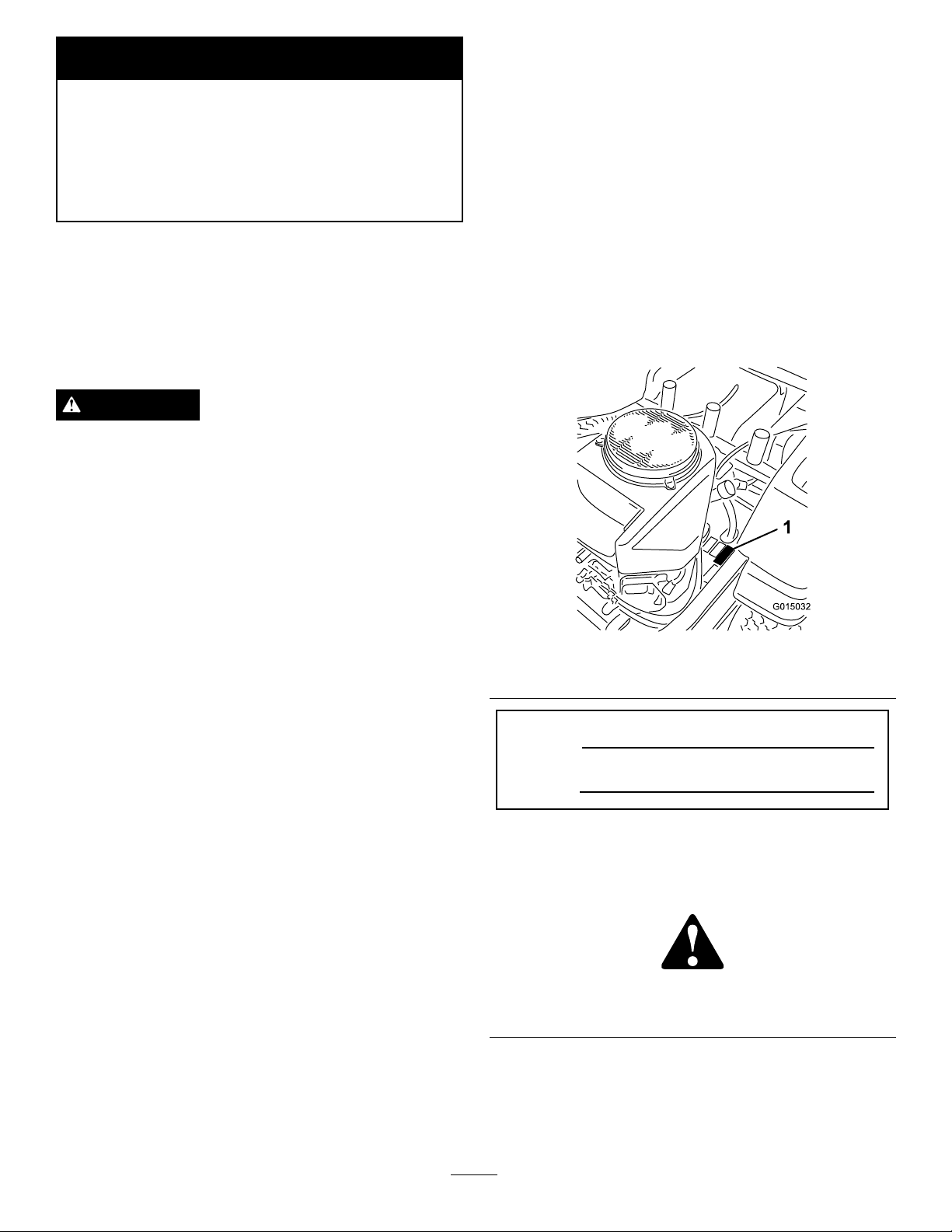
information,contactanAuthorizedServiceDealerorT oro
CustomerServiceandhavethemodelandserialnumbersof
yourproductready .Figure1identiesthelocationofthe
modelandserialnumbersontheproduct.Writethenumbers
inthespaceprovided.
Replaceallpartsincluding,butnotlimitedto,tires,
belts,blades,andfuelsystemcomponentswith
originalT oroparts.
Theenclosed
informationregardingtheUSEnvironmentalProtection
Agency(EPA)andtheCaliforniaEmissionControl
Regulationofemissionsystems,maintenance,and
warranty.Replacementsmaybeorderedthroughthe
enginemanufacturer.
Formodelswithstatedenginehorsepower,thegross
horsepoweroftheenginewaslaboratorytestedbytheengine
manufacturerinaccordancewithSAEJ1995andratedto
J2723.
Engine Owner's Man ual
issuppliedfor
Figure1
1.Modelandserialnumberlocation
ModelNo.
SerialNo.
Thismanualidentiespotentialhazardsandhassafety
messagesidentiedbythesafetyalertsymbol(Figure2),
whichsignalsahazardthatmaycauseseriousinjuryordeath
ifyoudonotfollowtherecommendedprecautions.
Figure2
1.Safetyalertsymbol
©2012—TheToro®Company
8111LyndaleAvenueSouth
Bloomington,MN55420
Thismanualuses2otherwordstohighlightinformation.
Importantcallsattentiontospecialmechanicalinformation
andNoteemphasizesgeneralinformationworthyofspecial
attention.
Contactusatwww.T oro.com.
2
PrintedintheUSA.
AllRightsReserved
Page 3

Contents
Introduction..................................................................2
Safety...........................................................................4
SafeOperatingPractices...........................................4
ToroRidingMowerSafety........................................6
SlopeIndicator.......................................................7
SafetyandInstructionalDecals.................................8
Setup...........................................................................13
1ConnectingtheBattery.........................................13
2CheckingtheMowerAdjustment...........................13
3CompletingtheSetup...........................................14
ProductOverview.........................................................15
Controls...............................................................16
Operation....................................................................17
ThinkSafetyFirst...................................................17
UsingtheRolloverProtectionSystem(ROPS)............18
AddingFuel...........................................................19
CheckingtheEngineOilLevel.................................20
OperatingtheParkingBrake....................................21
OperatingtheThrottle............................................21
OperatingtheChoke...............................................21
OperatingtheIgnitionSwitch..................................21
StartingandStoppingtheEngine..............................22
OperatingtheMowerBladeControlSwitch
(PTO)...............................................................23
TheSafetyInterlockSystem.....................................23
DrivingForwardorBackward..................................24
StoppingtheMachine.............................................25
AdjustingtheHeightofCut.....................................25
AdjustingtheAnti-ScalpRollers...............................26
PositioningtheSeat................................................27
AdjustingtheMotionControlLevers........................27
PushingtheMachinebyHand..................................28
UsingtheSideDischarge.........................................28
OperatingTips......................................................29
Maintenance.................................................................30
RecommendedMaintenanceSchedule(s)......................30
PremaintenanceProcedures........................................31
RaisingtheSeat......................................................31
Lubrication...............................................................31
GreasingtheBearings.............................................31
EngineMaintenance..................................................32
ServicingtheAirCleaner.........................................32
ServicingtheEngineOil..........................................33
ServicingtheSparkPlug..........................................35
CleaningtheCoolingSystem....................................36
FuelSystemMaintenance...........................................36
ReplacingtheFuelFilter..........................................36
ServicingtheEmissionsFilter..................................37
ElectricalSystemMaintenance....................................38
ServicingtheBattery...............................................38
ServicingtheFuses.................................................39
DriveSystemMaintenance.........................................40
CheckingtheTirePressure......................................40
HydraulicSystemMaintenance....................................40
CheckingtheHydraulicOilLevel..............................40
ChangingtheHydraulicSystemFilterand
Oil....................................................................40
MowerDeckMaintenance...........................................43
ServicingtheCuttingBlades.....................................43
MowerDeckLeveling.............................................45
InspectingtheBelts................................................47
ReplacingtheMowerBelt........................................47
RemovingtheMower..............................................48
InstallingtheMower...............................................50
ReplacingtheGrassDeector..................................50
Cleaning...................................................................51
WashingtheUndersideoftheMower........................51
WasteDisposal.......................................................52
Storage........................................................................52
CleaningandStorage..............................................52
Troubleshooting...........................................................54
Schematics...................................................................56
3
Page 4

Safety
ThismachinemeetsorexceedstheB71.1-2012
specicationsoftheAmericanNationalStandards
Institute,ineffectatthetimeofproduction.However,
improperuseormaintenancebytheoperatororowner
canresultininjury.Toreducethepotentialforinjury,
complywiththesesafetyinstructionsandalwayspay
attentiontothesafetyalertsymbol,whichmeans
CAUTION,WARNING,orDANGER-"personalsafety
instruction."Failuretocomplywiththeinstructionmay
resultinpersonalinjuryordeath.
•Disengagebladeswhennotmowing.Stoptheengine,
waitforallpartstocometoacompletestopandremove
thekeybeforecleaningthemachine,removingthegrass
catcheroruncloggingthedischargechute.
•Operatethemachineonlyindaylightorgoodarticial
light.
•Donotoperatethemachinewhileundertheinuence
ofalcoholordrugs.
•Watchfortrafcwhenoperatingnearorcrossing
roadways.
•Useextracarewhenloadingorunloadingthemachine
intoatrailerortruck.
SafeOperatingPractices
Thisproductiscapableofamputatinghandsandfeetand
throwingobjects.Alwaysfollowallsafetyinstructionsto
avoidseriousinjuryordeath.
ThefollowinginstructionsarefromANSIstandard
B71.1-2012.AllthelanguagewithinthisANSIstandard
appliestothismachine;however,duetotheapplicationof
thestandardacrossmanydifferenttypesofproductssome
statementscanseemgeneralormisleading.Intheseinstances,
Torohasrenedthestatementtoconveythemeaningofthe
standardwhilebettermatchingtheproductthisOperator's
Manualpertains.Safetyinformationinadditiontothe
instructionsfoundintheANSIstandardbelowcanbefound
inToroRidingMowerSafetyattheendofthissection.
GeneralOperation
•Read,understand,andfollowallinstructionsinthe
operator'smanualandonthemachinebeforestarting.
•Donotputhandsorfeetnearrotatingpartsorunderthe
machine.Keepclearofthedischargeopeningatalltimes.
•Allowonlyresponsibleadultswhoarefamiliarwiththe
instructionstooperatethismachine.
•Cleartheareaofobjectssuchasrocks,toys,wire,etc.,
whichcouldbepickedupandthrownbytheblade.
•Besuretheareaisclearofotherpeoplebeforemowing.
Stopthemachineifanyoneentersthearea.
•Nevercarrypassengers.
•Donotmowinreverseunlessabsolutelynecessary.
Alwayslookdownandbehindbeforeandwhilebacking
up.
•Neverdirectdischargedmaterialtowardanyone.
•Donotoperatethemachinewithoutdeector,discharge
coverorentiregrasscollectionsysteminplaceand
working.
•Bealert,slowdownandusecautionwhenmakingturns.
Lookbehindandtothesidebeforechangingdirections.
•Neverleavearunningmachineunattended.Alwaysturn
offblades,setparkingbrake,stopengine,andremovekey
beforedismounting.
•Alwaysweareyeprotectionwhenoperatingthemachine.
•Dataindicatesthatoperators,age60yearsandabove,are
involvedinalargepercentageofridingmower-related
injuries.Theseoperatorsshouldevaluatetheirability
tooperatetheridingmowersafelyenoughtoprotect
themselvesandothersfromseriousinjury.
•Alwaysfollowtherecommendationsforuseofwheel
weightsorcounterweights.
•Lightningcancausesevereinjuryordeath.Iflightning
isseenorthunderisheardinthearea,donotoperate
themachine;seekshelter.
SlopeOperation
Slopesareamajorfactorrelatedtolossofcontroland
tip-overaccidents,whichcanresultinsevereinjuryordeath.
Operationonallslopesrequiresextracaution.Ifyoucannot
backuptheslopeorifyoufeeluneasyonit,donotmowit.
•Donotmowslopesgreaterthan15degrees.
•Watchforholes,ruts,bumps,rocks,orotherhidden
objects.Uneventerraincouldoverturnthemachine.Tall
grasscanhideobstacles.
•Choosealowgroundspeedsoyouwillnothavetostop
whileoperatingonaslope.
•Donotmowslopeswhengrassiswet.Slippery
conditionsreducetractionandcouldcauseslidingand
lossofcontrol.
•Avoidstarting,stopping,orturningonaslope.Ifthetires
losetraction,disengagetheblade(s)andproceedslowly
straightdowntheslope.
•Alwayskeepthedrivewheelsengagedwhengoingdown
slopes.Donotshifttoneutralandcoastdownhill.
•Keepallmovementonslopesslowandgradual.Donot
makesuddenchangesinspeedordirection,whichcould
causethemachinetorollover.
•Removeormarkobstaclessuchasrocks,treelimbs,etc.
fromthemowingarea.Tallgrasscanhideobstacles.
•Avoidsuddenstartswhenmowinguphillbecausethe
mowermaytipbackwards.
4
Page 5

•Beawarethatlossoftractionmayoccurgoingdownhill.
Weighttransfertothefrontwheelsmaycausedrive
wheelstoslipandcauselossofbrakingandsteering.
•Useextracarewhileoperatingmachinewithgrass
catchersorotherattachments;theycanaffectthestability
ofthemachine.Donotuseonsteepslopes.
•Donottrytostabilizethemachinebyputtingyourfoot
ontheground.
•Donotmowneardrop-offs,ditches,embankments,or
water.Themachinecouldsuddenlyrolloverifawheel
goesovertheedgeoriftheedgecavesin.
•Useawalkbehindmowerand/orahandtrimmernear
drop-offs,ditches,steepbanksorwater.
UsingtheRolloverProtectionSystem
(ROPS)
•Keeptherollbarintheraisedandlockedpositionand
usetheseatbeltwhenoperatingthemachine.
•Becertainthattheseatbeltcanbereleasedquicklyin
theeventofanemergency.
•Beawarethereisnorolloverprotectionwhentheroll
barisdown.
•ChecktheareatobemowedandneverfoldtheROPSin
areaswherethereareslopes,dropoffsorwater.
•Lowertherollbaronlywhenabsolutelynecessary.Donot
weartheseatbeltwiththerollbarfoldeddown.
•Checkcarefullyforoverheadclearances(i.e.branches,
doorways,electricalwires)beforedrivingunderany
objectsanddonotcontactthem.
Children
Tragicaccidentscanoccuriftheoperatorisnotalerttothe
presenceofchildren.Childrenareoftenattractedtothe
machineandthemowingactivity.Neverassumethatchildren
willremainwhereyoulastsawthem.
•Keepchildrenoutofthemowingareaandinthewatchful
careofaresponsibleadultotherthantheoperator.
•Bealertandturnthemachineoffifchildrenenterthe
area.
•Beforeandwhilebackingorchangingdirection,look
behind,down,andside-to-sideforsmallchildren.
•Nevercarrychildren,evenwiththebladesoff.Theymay
falloffandbeseriouslyinjuredorinterferewithsafe
machineoperation.
•Childrenwhohavebeengivenridesinthepastmay
suddenlyappearinthemowingareaforanotherrideand
berunoverorbackedoverbythemachine.
•Neverallowchildrentooperatethemachine.
•Useextremecarewhenapproachingblindcorners,end
ofafence,shrubs,trees,orotherobjectsthatmayblock
yourviewofachild.
Towing
Ahitchkitisavailableforthismachineandcanbeobtained
bycontactinganAuthorizedToroDealer.Donottow
withoutrstinstallingthismanufacturerapprovedhitch.The
followingguidelinesapplywhentowingwiththeapproved
hitchkitinstalled.
•Towonlywithamachinethathasahitchdesignedfor
towing.Donotattachtowedequipmentexceptatthe
hitchpoint.
•Followthemanufacturer'srecommendationforweight
limitsfortowedequipmentandtowingonslopes.
•Neverallowchildrenorothersinorontowedequipment.
•Onslopes,theweightofthetowedequipmentmaycause
lossoftractionandlossofcontrol.
•Travelslowlyandallowextradistancetostop.
Service
SafeHandlingofFuel:
Toavoidpersonalinjuryorpropertydamage,useextreme
careinhandlinggasoline.Gasolineisextremelyammable
andthevaporsareexplosive.
•Extinguishallcigarettes,cigars,pipesandothersources
ofignition.
•Useonlyanapprovedfuelcontainer.
•Neverremovethefuelcaporaddfuelwhentheengineis
running.
•Allowtheenginetocoolbeforerefueling.
•Neverrefuelthemachineindoors.
•Neverstorethemachineorfuelcontainerwherethereis
anopename,spark,orpilotlightsuchasonawater
heaterorotherappliances.
•Neverllcontainersinsideavehicleoronatruckor
trailerwithaplasticliner.Alwaysplacecontainersonthe
groundawayfromyourvehiclebeforelling.
•Removegas-poweredequipmentfromthetruckortrailer
andrefuelitontheground.Ifthisisnotpossible,then
refuelsuchequipmentwithaportablecontainer,rather
thanfromagasolinedispensernozzle.
•Keepthenozzleincontactwiththerimofthefueltank
orcontaineropeningatalltimesuntilthefuelingis
complete.Donotuseanozzlelock-opendevice.
•Iffuelisspilledonclothing,changeclothingimmediately.
•Neveroverllthefueltank.Replacegascapandtighten
securely.
GeneralService:
•Neveroperateamachineinsideaclosedarea.Engine
exhaustcontainscarbonmonoxide,whichisanodorless,
deadlypoisonthatcankillyou.
•Keepallnutsandboltstight,especiallytheblade
attachmentbolts,andtobesuretheequipmentisinsafe
workingcondition.
5
Page 6

•Neverinterferewiththeintendedfunctionofasafety
deviceorreducetheprotectionprovidedbyasafety
device.Checktheirproperoperationregularly.
•Keepmachinefreeofgrass,leaves,orotherdebrisbuild
up.Cleanupoilorfuelspillageandremoveanyfuel
soakeddebris.Allowmachinetocoolbeforestoring.
•Ifyoustrikeaforeignobject,stopandinspectthe
machine.Repair,ifnecessary,beforerestarting.
•Nevermakeanyadjustmentsorrepairswiththeengine
running.
•Checkgrasscatchercomponentsandthedischargeguard
frequentlyandreplacewithmanufacturer’srecommended
parts,whennecessary.
•Mowerbladesaresharp.Wrapthebladeorweargloves,
anduseextracautionwhenservicingthem.
•Checkforproperbrakeoperationfrequently.Adjustand
serviceasrequired.
•Maintainorreplacesafetyandinstructionlabelsas
necessary.
•UseonlygenuineTororeplacementpartstoensurethat
originalstandardsaremaintained.
ToroRidingMowerSafety
ThefollowinglistcontainssafetyinformationspecictoToro
productsorothersafetyinformationthatyoumustknowthat
maynotbeincludedintheANSIstandards.
•Stoptheengine,movethemotioncontrolleverstoneutral
andoutwardtotheparkposition,disengagetheblade
controlswitch,removekeybeforeanddisconnectspark
plugwire(s)performinganyservice,repairs,maintenance
oradjustments.
•Keephands,feet,hair,andlooseclothingawayfrom
attachmentdischargearea,undersideofmowerandany
movingpartswhileengineisrunning.
•Donottouchequipmentorattachmentpartswhichmay
behotfromoperation.Allowtocoolbeforeattempting
tomaintain,adjustorservice.
•Batteryacidispoisonousandcancauseburns.Avoid
contactwithskin,eyes,andclothing.Protectyourface,
eyes,andclothingwhenworkingwithabattery.
•Batterygasescanexplode.Keepcigarettes,sparksand
amesawayfrombattery.
•UseonlyT oroapprovedattachments.Warrantymaybe
voidedifusedwithunapprovedattachments.
•Ifloadingthemachineontoatrailerortruck,useasingle,
full-widthramponly.Therampangleshouldnotexceed
15degrees.
6
Page 7

SlopeIndicator
G011841
Figure3
Thispagemaybecopiedforpersonaluse.
1.Themaximumslopeyoucansafelyoperatethemachineonis15degrees.Usetheslopecharttodeterminethedegreeofslope
ofhillsbeforeoperating.Donotoperatethismachineonaslopegreaterthan15degrees.Foldalongtheappropriateline
tomatchtherecommendedslope.
2.Alignthisedgewithaverticalsurface,atree,building,fencepole,etc.
3.Exampleofhowtocompareslopewithfoldededge.
7
Page 8

SafetyandInstructionalDecals
Safetydecalsandinstructionsareeasilyvisibletotheoperatorandarelocatednearanyareaofpotential
danger.Replaceanydecalthatisdamagedorlost.
99-8936
1.Machinespeed4.Neutral
2.Fast5.Reverse
3.Slow
107-3069
1.Warning-thereisnorolloverprotectionwhentherollbaris
down.
2.Toavoidinjuryordeathfromarolloveraccident,keepthe
rollbarinthefullyraisedandlockedpositionandwear
theseatbelt.Lowertherollbaronlywhenabsolutely
necessary;donotweartheseatbeltwhentherollbaris
down.
3.ReadtheOperator’smanual;driveslowlyandcarefully .
115-9625
1.Parking
brake—disengaged
2.Parkingbrake—engaged
Manufacturer'sMark
1.Indicatesthebladeisidentiedasapartfromtheoriginal
machinemanufacturer.
8
Page 9
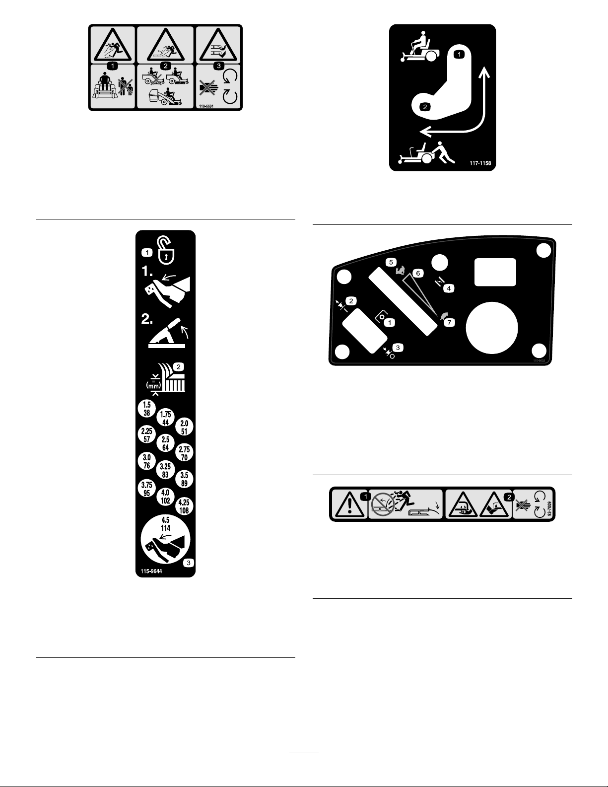
110-6691
1.Thrownobjecthazard—keepbystandersasafedistance
fromthemachine.
2.Thrownobjecthazard,mower—donotoperatewithoutthe
deector,dischargecover,orgrasscollectionsystemin
place.
3.Cutting/dismembermentofhandorfoot—stayawayfrom
movingparts.
1.Bypassleverpositionfor
operatingthemachine.
117–1158
2.Bypassleverpositionfor
pushingthemachine.
115-9632
115-9644
1.Pressthepedalandlifttheheightofcutlevertounlockthe
deckposition.
2.Heightofcut
3.Pressthepedaltomovethedecktothetransportposition
1.Powertake-off(PTO),
Bladecontrolswitchon
somemodels
2.Bladecontrolswitch—On6.Continuousvariable
3.Bladecontrolswitch—Off7.Slow
4.Choke
5.Fast
setting
93-7009
1.Warning—don'toperatethemowerwiththedeectorupor
removed;keepthedeectorinplace.
2.Cutting/dismembermenthazardofhandorfoot,mower
blade—stayawayfrommovingparts.
9
Page 10

115-9630
1.ReadtheOperator'sManualbeforeperformingany
maintenance.
2.Checktheengineoilevery8hours5.Checkthecasterwheeltirepressureevery25hours
3.Checkthedrivewheeltirepressureevery25hours
4.Checkthehydraulicoilevery25hours
6.Lubricatethecasterwheelevery25hours
BatterySymbols
Someorallofthesesymbolsareonyourbattery
1.ReadtheOperator's
Manual.
2.Heightofcut
112-9840
3.Removetheignitionkey
andreadtheinstructions
beforeservicingor
performingmaintenance.
1.Explosionhazard
2.Nore,opename,or
smoking.
3.Causticliquid/chemical
burnhazard
4.Weareyeprotection9.Flusheyesimmediately
5.ReadtheOperator's
Manual.
6.Keepbystandersasafe
distancefromthebattery .
7.Weareyeprotection;
explosivegasescan
causeblindnessandother
injuries
8.Batteryacidcancause
blindnessorsevereburns.
withwaterandgetmedical
helpfast.
10.Containslead;donot
discard.
1.Lock
2.ReadtheOperator'sManual
117-5344
10
Page 11
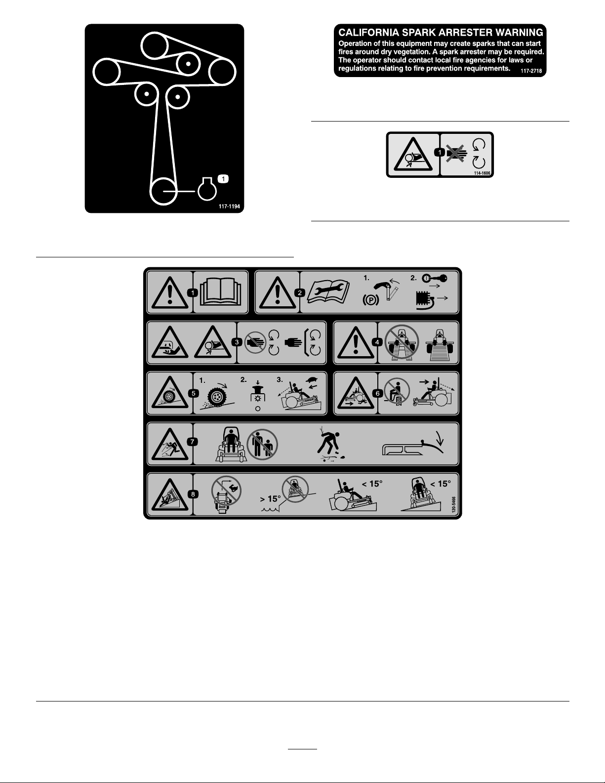
117–2718
Model74845only
114-1606
1.Entanglementhazard,belt—keepallguardsinplace.
117-1194
1.Engine
120-5466
1.Warning—readtheOperator'sManual.5.Lossoftraction/controlhazard,slopes—lossoftraction/control
2.Warning—readtheinstructionsbeforeservicingorperforming
maintenance;movethemotioncontrolleverstothepark
(brake)position,removetheignitionkeyanddisconnectthe
sparkplugwire.
3.Cutting/dismembermenthazard,mowerblade;entanglement
hazard,belt—stayawayfrommovingparts,keepallguards
andshieldsinplace.
4.Warning—donotusesplitramps,useafullrampwhen
transportingmachine.
onaslope,disengagethebladecontrolswitch(PTO),
proceedofftheslopeslowly.
6.Crushing/dismembermenthazardofbystanders,
reversing—donotcarrypassengers,lookbehindanddown
whenreversing.
7.Thrownobjecthazard—keepbystandersasafedistancefrom
themachine,pickupdebrisbeforeoperating,keepdeector
inplace.
8.Tippinghazard—donotturnathighspeeds,donotoperate
neardrop-offsonslopesgreaterthan15degrees,donotmow
slopesgreaterthan15degrees,avoidsuddenandsharp
turnswhileonslopes.
11
Page 12

119-8983
1.Fuel2.Full
1.Fuel2.Full
3.Half
4.Empty
119-8986
3.Half
4.Empty
1.Fuel2.Full
119-8987
3.Half
4.Empty
12
Page 13
Setup
G010257
1
2
3
5
4
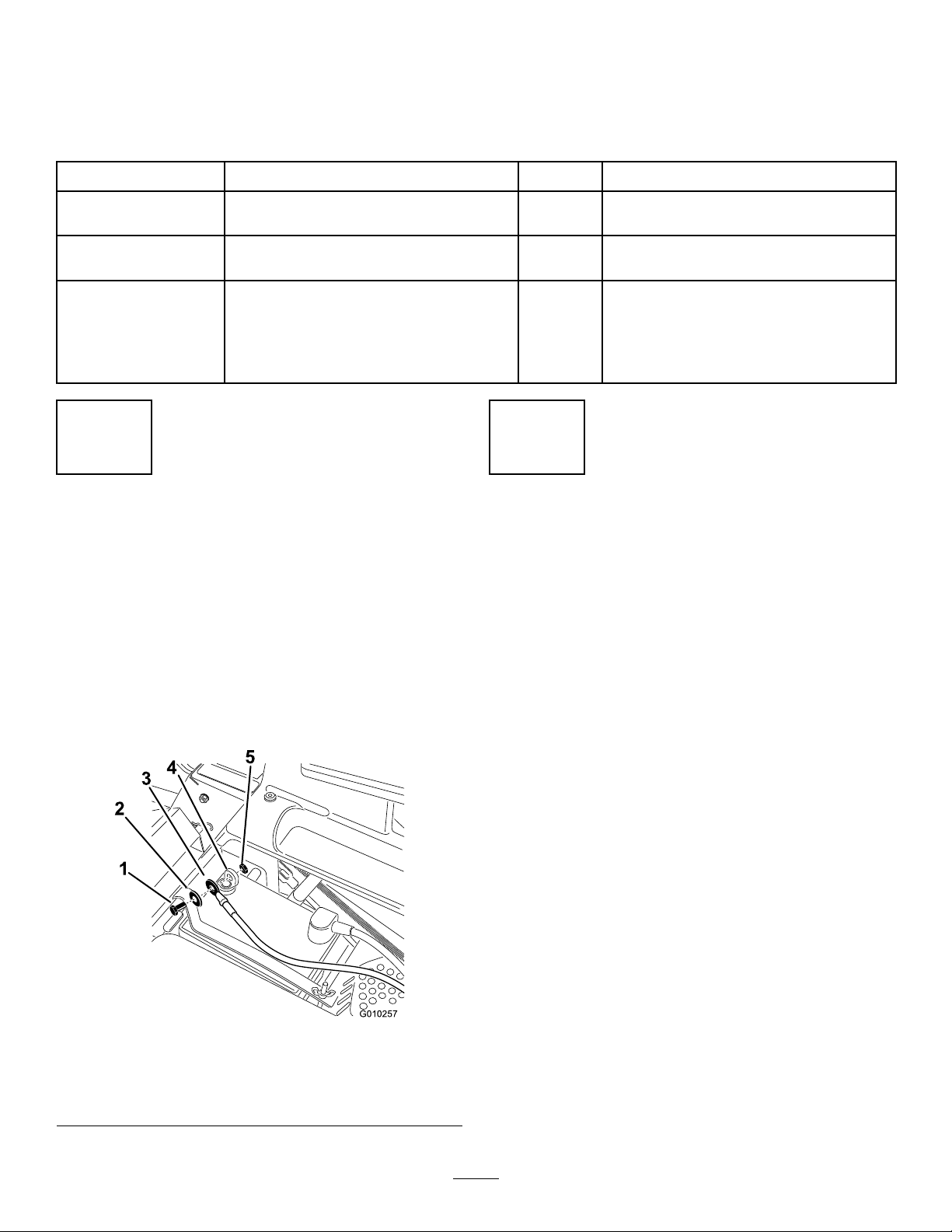
LooseParts
Usethechartbelowtoverifythatallpartshavebeenshipped.
ProcedureDescription
1
2
3
Nopartsrequired
Nopartsrequired
IgnitionKey1
Hosecoupling1
Operator'sManual
EngineOperator'sManual
OperatorTrainingMaterial
1
ConnectingtheBattery
NoPartsRequired
Procedure
1.Locatethebatteryandnegativebatterycableinthe
centerofthemachine.
2.Removetheblackplasticcapfromthenegativebattery
post.Removethefastenersfromthenegativebattery
cableandusethemtosecurethenegativebatterycable
tothenegativebatterypost(Figure4).
Qty.
–
–
1
1
1
Connectthebattery.
Checkthemoweradjustment.
CompletetheSetup.
Use
2
CheckingtheMower Adjustment
NoPartsRequired
Procedure
Adjusttheside-to-sidelevelandthefront-to-rearbladeslope.
UsetherelevantproceduresintheOperator'sManualtoverify
thedeckislevelandmakeanyadjustmentsasnecessary.Refer
totheOperator'sManualformoreinformation.
1.Bolt4.Negativebatterypost
2.Washer5.Nut
3.Negativebatterycable
Figure4
13
Page 14

ReviewtheRemainingParts
Keepallthefollowingitemswiththemachine:
3
•IgnitionKey
CompletingtheSetup
Partsneededforthisprocedure:
1IgnitionKey
1Hosecoupling
1
Operator'sManual
1
EngineOperator'sManual
1
OperatorTrainingMaterial
Procedure
SettingUptheMotionControlLevers
Ifneeded,removetheupperbolt,washerandnutandraise
themotioncontrolleverstotheuprightposition.Securethe
motioncontrollevers.RefertoAdjustingtheMotionControl
LeversintheOperationSection.
RaisingtheROPS
RaisetheROPSintotheuprightpositionandsecureitin
place.RefertoUsingtheRolloverProtectionSystem(ROPS)
intheOperationSection.
•Hosecoupling
•Operator'sManual
•EngineOperator'sManual
•ViewtheOperatortrainingmaterialbeforeoperatingthe
machine.
CheckingtheTirePressure
Checkthefrontandreartiresforproperination.Referto
CheckingtheTirePressureintheOperator'sManualforthe
recommendedinationpressure.
CheckingtheSideDischargeChute
Removethepackingrestraintholdingthesidedischargechute
upandlowerthechuteintoplace.
CheckingtheEngineOilLevel
Beforeyoustarttheengineandusethemachine,checkthe
oillevelintheenginecrankcase;refertoCheckingtheOil
LevelintheOperator'sManual.
CheckingtheHydraulicOilLevel
CheckingtheMowerAdjustment
Themowerdeckwasleveledatthefactory.Ifthemower
isnotcuttinglevel,adjusttheside-to-sidelevelandthe
front-to-rearbladeslope.SeetheOperator'sManualforthe
properprocedure.
Beforeyoustarttheengineandusethemachine,checkthe
hydraulicoillevelinthereservoirbehindtheseat;referto
CheckingtheOilLevelintheOperator'sManual.
14
Page 15
ProductOverview
G015763
1
2
3
4
5
6
7
8
9
10
G014766
1
2
3
4
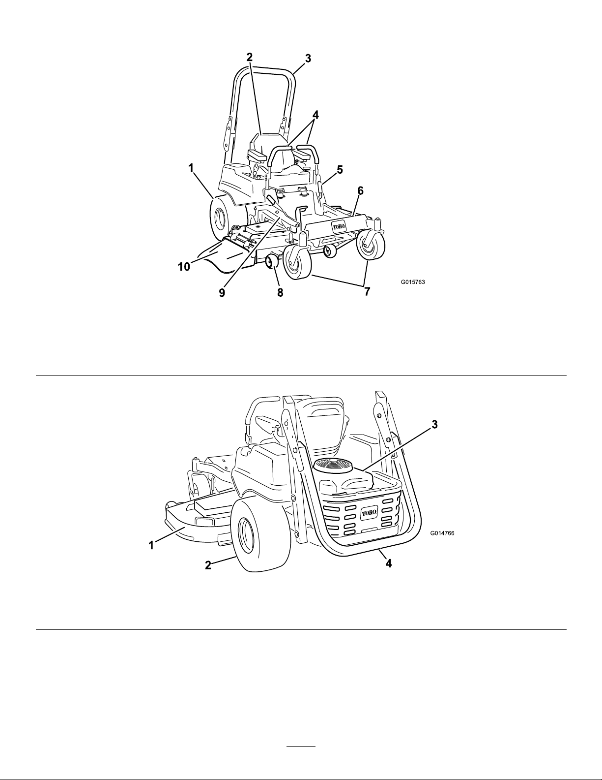
Figure5
1.Drivewheel4.Motioncontrollevers7.Frontcasterwheel
2.Operatorseat
3.Rolloverprotectionsystem
(ROPS)
1.MowerDeck3.Engine
2.Drivewheel
5.Parkingbrake8.Anti-scalproller
6.Footrest
9.Footpedaldeckliftand
height-of-cut
Figure6
4.Rolloverprotectionsystem(ROPS),foldeddown
10.Deector
15
Page 16
Controls
g017722
1
2
3
4
5
G020318
1
1
Becomefamiliarwithallthecontrolsbeforeyoustartthe
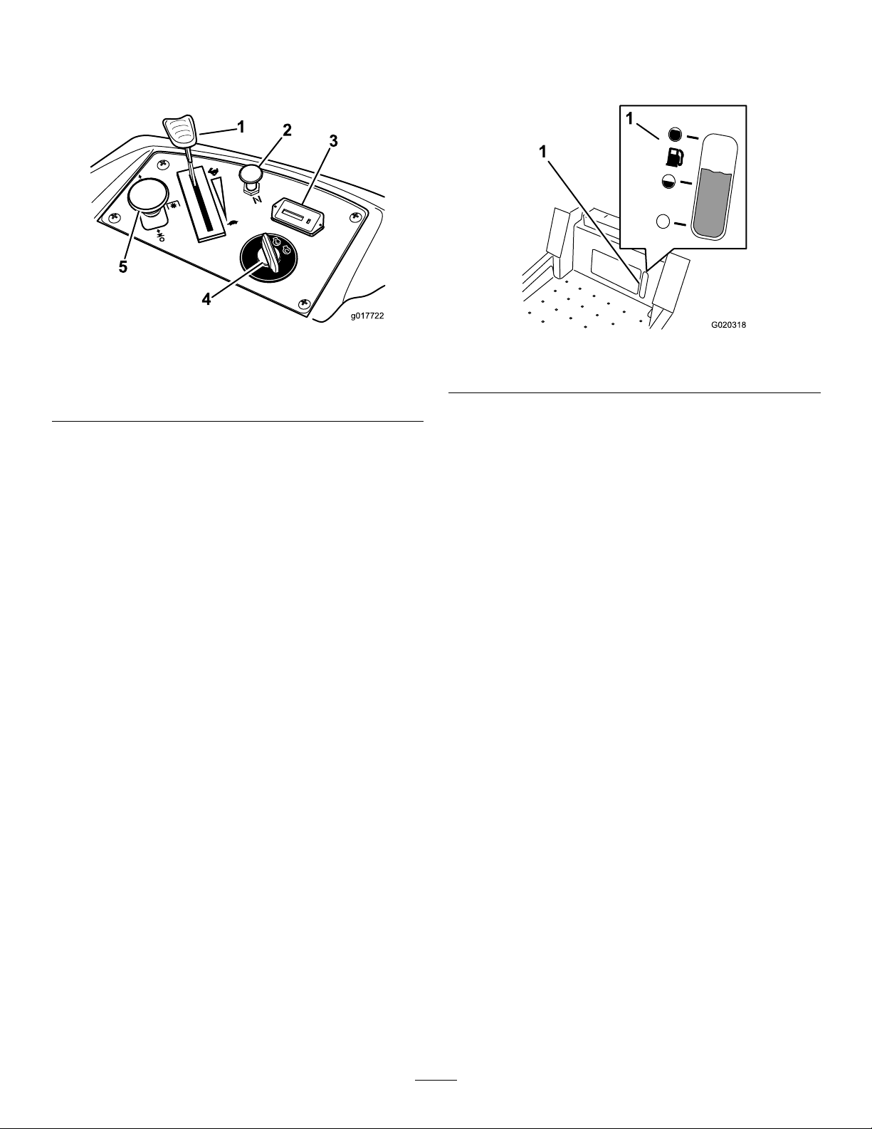
engineandoperatethemachine(Figure7).
FuelGauge
Thefuelwindowlocatedbelowtheoperatorpositioncanbe
usedtoverifythelevelofgasolineinthetank(Figure8).
Figure7
1.Throttlecontrol4.Ignitionswitch
2.Choke5.Bladecontrolswitch(PTO)
3.Hourmeter
IgnitionSwitch
Theignitionswitchhasthreepositions:Start,RunandOff.
ThekeywillturntoStartandmovebacktoRunuponrelease.
TurningthekeytotheOffpositionwillstoptheengine;
however,alwaysremovethekeywhenleavingthemachineto
preventtheenginefromaccidentallystarting(Figure7).
ThrottleControl
ThethrottlecontrolisvariablebetweenFastandSlow.
Movingthrottleleverforwardwillincreaseenginespeedand
movingthrottlelevertotherearwilldecreaseenginespeed.
Movingthethrottleforwardintothedetentisfullthrottle
(Figure7).
Choke
Figure8
1.Fuelgaugewindow
MotionControlLevers
Themotioncontrolleversarespeedsensitivecontrolsof
independentwheelmotors.Movingaleverforwardor
backwardturnsthewheelonthesamesideforwardorin
reverse;wheelspeedisproportionaltotheamountthelever
ismoved.Movethecontrolleversoutwardfromthecenter
totheneutrallockpositionandexitthemachine(Figure5).
Alwayspositionthemotioncontrolleversintotheneutrallock
positionwhenyoustopthemachineorleaveitunattended.
ParkingBrakeLever
Theparkingbrakeleverislocatedonleftsideoftheconsole
(Figure5).Thebrakeleverengagesaparkingbrakeonthe
drivewheels.Pulltheleverupandrearwardtoengagethe
brake.Pushtheleverforwardanddowntodisengagethe
brake.
FootPedalDeckLiftSystem
Usethechoketostartacoldengine.Pullthechokeknobup
toengageit.Pushdownonthechokeknobtodisengageit.
BladeControlSwitch(PowerTake-Off)
Thebladecontrolswitch,representedbyapowertake-off
(PTO)symbol,engagesanddisengagespowertothemower
blades(
HourMeter
Thehourmeterrecordsthenumberofhoursthebladeshave
operated.Itoperateswhenthebladecontrolswitch(PTO)is
engaged.Usethesetimesforschedulingregularmaintenance
(Figure7).
Figure7).
Thefootpedaldeckliftsystemallowstheoperatortolower
andraisethedeckfromtheseatedposition.Theoperatorcan
usethefootpedaltoliftthedeckbrieytoavoidobstacles
orlockthedeckinthehighestheight-of-cutortransport
position(
Figure5).
Height-of-CutLever
Theheight-of-cutleverworkswiththefootpedaltolockthe
deckinaspeciccuttingheight.Onlyadjusttheheightofcut
whilemachineisnotmoving(
Figure5).
Attachments/Accessories
AselectionofToroapprovedattachmentsandaccessoriesare
availableforusewiththemachinetoenhanceandexpand
itscapabilities.ContactyourAuthorizedServiceDealeror
16
Page 17
Distributororgotowww .Toro.comforalistofallapproved
G015033
1
2
3
attachmentsandaccessories.
Operation
Note:Determinetheleftandrightsidesofthemachine
fromthenormaloperatingposition.
ThinkSafetyFirst
Pleasecarefullyreadallofthesafetyinstructionsanddecals
inthesafetysection.Knowingthisinformationcouldhelp
you,yourfamily,pets,orbystandersavoidinjury.
DANGER
Mowingonwetgrassorsteepslopescancause
slidingandlossofcontrol.
Wheelsdroppingoveredgescancauserollovers,
whichmayresultinseriousinjury,deathor
drowning.
Alossoftractionisalossofsteeringcontrol.
Toavoidlossofcontrolandpossibilityofrollover:
•Donotmowneardrop-offsornearwater.
•Donotmowslopesgreaterthan15degrees.
•Reducespeedanduseextremecautionon
slopes.
•Whenmowingslopes,graduallyworkfrom
lowertohigherareasontheincline.
•Avoidsuddenturnsorrapidspeedchanges.
•Turnup,intoaninclinewhenchanging
directionsonslopes.Turningdowntheslope
reducestraction.
•Attachmentschangethehandlingcharacteristics
ofthemachine.Useextracautionwhenusing
attachmentswiththemachine.
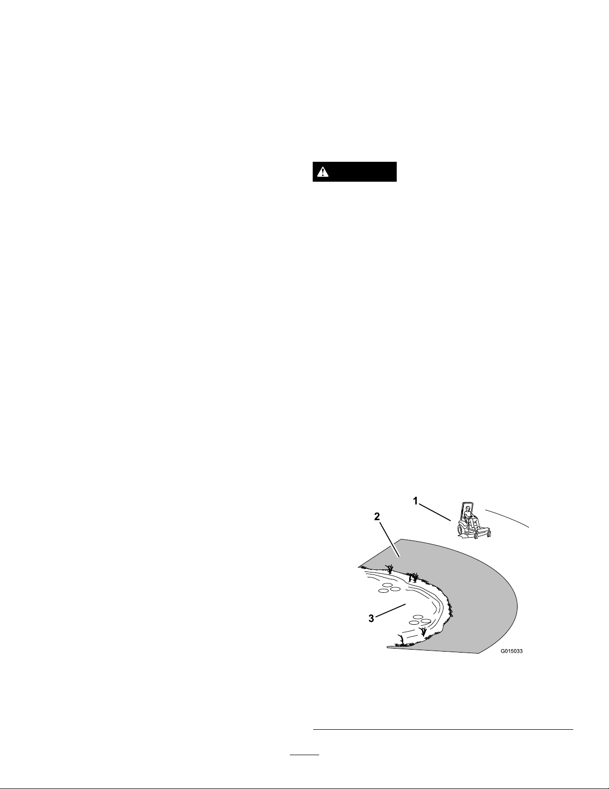
Figure9
1.SafeZone-usethemachinehere
2.Usewalkbehindmowerand/orhandtrimmerneardrop-offs
andwater.
3.Water
17
Page 18
UsingtheRolloverProtection
G015034
G015035
1
2
3
2
System(ROPS)
WARNING
Toavoidinjuryordeathfromrollover:keepthe
rollbarintheraisedlockedpositionandusethe
seatbelt.
Figure11
WARNING
Thereisnorolloverprotectionwhentherollbaris
inthedownposition.
•Lowertherollbaronlywhenabsolutely
necessary.
•Donotweartheseatbeltwhentherollbaris
inthedownposition.
•Driveslowlyandcarefully.
•Raisetherollbarassoonasclearancepermits.
•Checkcarefullyforoverheadclearances(i.e.
branches,doorways,electricalwires)before
drivingunderanyobjectsanddonotcontact
them.
Important:Lowertherollbaronlywhenabsolutely
necessary.
1.Toraisetherollbar,removethehaircotterpinand
removethelockingpins.
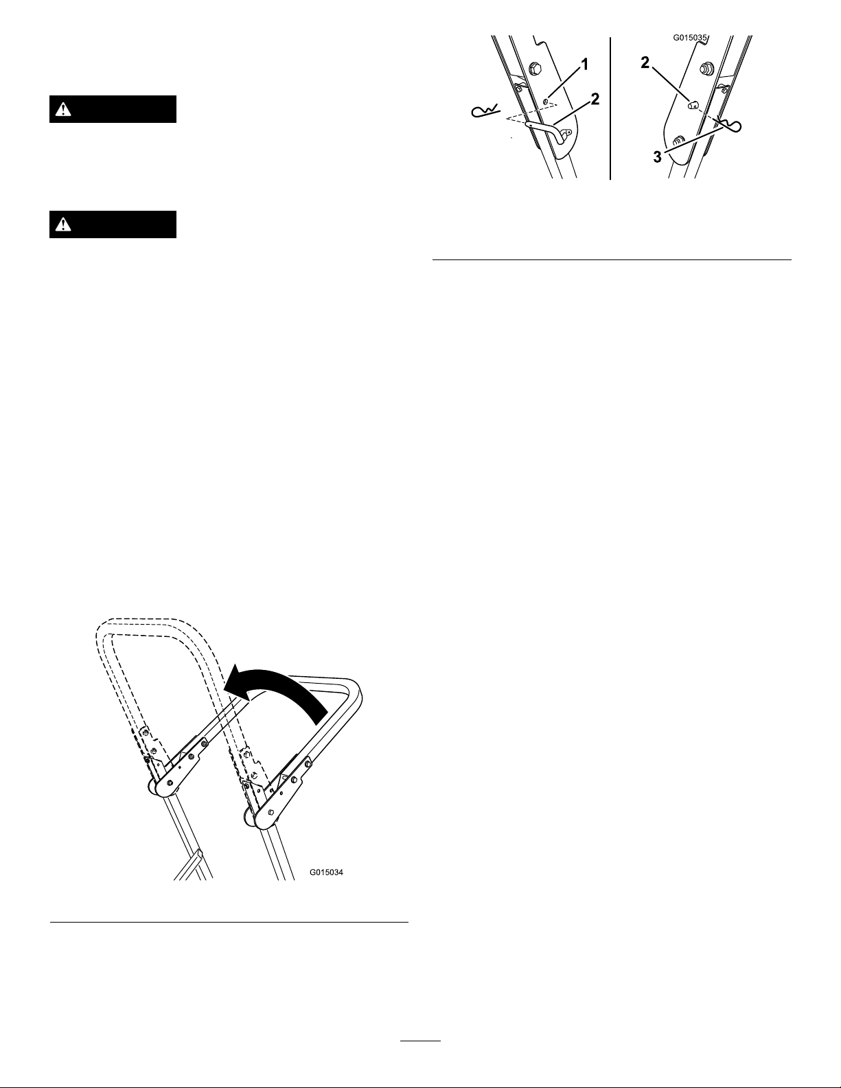
2.Raisetherollbartotheuprightposition(
Figure10).
1.HoleinROPS
2.Lockingpin
4.Tolowertherollbar,removethehaircotterpinand
removethelockingpin(Figure11).
5.Lowertherollbartothedownposition.
6.Usethe2lockingandcotterpinstosecurethebar.
3.Hairpincotter
Figure10
Important:Alwaysusetheseatbeltwiththeroll
barintheraisedposition.
3.Installthelockingpins.Securethepinsbyinstallingthe
haircotterpin(
Figure11).
18
Page 19

AddingFuel
•Forbestresults,useonlyclean,fresh,unleadedgasoline
withanoctaneratingof87orhigher((R+M)/2rating
method).
•Oxygenatedfuelwithupto10%ethanolor15%MTBE
byvolumeisacceptable.
•DoNotuseethanolblendsofgasoline(suchasE15
orE85)withmorethan10%ethanolbyvolume.
Performanceproblemsand/orenginedamagemayresult
whichmaynotbecoveredunderwarranty.
•DoNotusegasolinecontainingmethanol.
•DoNotstorefueleitherinthefueltankorfuelcontainers
overthewinterunlessafuelstabilizerisused.
•DoNotaddoiltogasoline.
DANGER
Incertainconditions,gasolineisextremely
ammableandhighlyexplosive.Areorexplosion
fromgasolinecanburnyouandothersandcan
damageproperty.
•Fillthefueltankoutdoors,inanopenarea,
whentheengineiscold.Wipeupanygasoline
thatspills.
DANGER
Incertainconditionsduringfueling,static
electricitycanbereleasedcausingasparkwhich
canignitethegasolinevapors.Areorexplosion
fromgasolinecanburnyouandothersandcan
damageproperty.
•Alwaysplacegasolinecontainersontheground
awayfromyourvehiclebeforelling.
•Donotllgasolinecontainersinsideavehicleor
onatruckortrailerbedbecauseinteriorcarpets
orplastictruckbedlinersmayinsulatethe
containerandslowthelossofanystaticcharge.
•Whenpractical,removegas-poweredequipment
fromthetruckortrailerandrefueltheequipment
withitswheelsontheground.
•Ifthisisnotpossible,thenrefuelsuch
equipmentonatruckortrailerfromaportable
container,ratherthanfromagasolinedispenser
nozzle.
•Ifagasolinedispensernozzlemustbeused,
keepthenozzleincontactwiththerimofthe
fueltankorcontaineropeningatalltimesuntil
fuelingiscomplete.
•Neverllthefueltankinsideanenclosedtrailer.
•Donotllthefueltankcompletelyfull.Add
gasolinetothefueltankuntilthelevelis6to13
mm(1/4to1/2inch)belowthebottomofthe
llerneck.Thisemptyspaceinthetankallows
gasolinetoexpand.
•Neversmokewhenhandlinggasoline,andstay
awayfromanopenameorwheregasoline
fumesmaybeignitedbyaspark.
•Storegasolineinanapprovedcontainerand
keepitoutofthereachofchildren.Neverbuy
morethana30-daysupplyofgasoline.
•Donotoperatewithoutentireexhaustsystemin
placeandinproperworkingcondition.
WARNING
Gasolineisharmfulorfatalifswallowed.Long-term
exposuretovaporscancauseseriousinjuryand
illness.
•Avoidprolongedbreathingofvapors.
•Keepfaceawayfromnozzleandgastankor
conditioneropening .
•Keepgasawayfromeyesandskin.
UsingStabilizer/Conditioner
Useafuelstabilizer/conditionerinthemachinetoprovide
thefollowingbenets:
•Fuelstabilizer/conditionerkeepsgasolinefreshduring
storageof90daysorless.Whenstoringthemachinefor
longerperiods,drainthefuelsystem.
•Itcleanstheenginewhileitruns
•Iteliminatesgum-likevarnishbuildupinthefuelsystem,
whichcauseshardstarting
Important:Donotusefueladditivescontaining
methanolorethanol.
Addthecorrectamountofgasstabilizer/conditionertothe
gas.
Note:Afuelstabilizer/conditionerismosteffectivewhen
mixedwithfreshgasoline.Tominimizethechanceofvarnish
depositsinthefuelsystem,usefuelstabilizeratalltimes.
19
Page 20

FuelGauge
G020318
1
1
G020304
1
2
3
4
Usethefuelwindowbelowtheoperatortoverifythelevelof
gasolinebeforellingthetank(Figure12).
Figure12
1.Fuelgaugewindow
FillingtheFuelTank
Makesuretheengineisshutoffandthemotioncontrolsare
intheparkposition.
Important:Donotoverllfueltank.Fillthefueltank
tothebottomofthellerneck.Theemptyspaceinthe
tankallowsthefueltoexpand.Overllingmayresultin
fuelleakageordamagetotheengineoremissionsystem.
1.Cleanaroundthefueltankcapandremovethecap.
Note:Youcanusethefuelwindowbelowthe
operatingpositionverifythepresenceofgasoline
beforellingthetank(Figure12).
2.Slowlyaddregular,unleadedgasolineuntilthefuel
reachesthebaseofthellerneckFigure13.
3.Installthefueltankcapsecurelyandtightenuntilit
“clicks.”Wipeupanygasolinethatmayhavespilled.
CheckingtheEngineOilLevel
Beforeyoustarttheengineandusethemachine,
checktheoillevelintheenginecrankcase;referto
CheckingtheEngineOilLevel(page33).
Figure13
20
Page 21

OperatingtheParkingBrake
1
2
G020305
1
2
G020306
G008946
G008959
1
2
START
RUN
STOP
G008947
Alwayssettheparkingbrakewhenyoustopthemachineor
leaveitunattended.
SettingtheParkingBrake
Figure14
ReleasingtheParkingBrake
1.Pulluponthechokeknobtoengagethechokebefore
usingtheignitionswitch(Figure17).
2.Pushdownonthechoketodisengagethechokeafter
theenginehasstarted(Figure17).
Figure17
1.On2.Off
OperatingtheIgnitionSwitch
Figure15
OperatingtheThrottle
ThethrottlecontrolcanbemovedbetweenFastandSlow
positions(
Alwaysusethefastpositionwhenturningonthemowerdeck
withthebladecontrolswitch(PTO).
Figure16).
1.TurntheignitionkeytotheStartposition(Figure18).
Whentheenginesstarts,releasethekey.
Important:Donotengagestarterformorethan5
secondsatatime.Iftheenginefailstostartallow
a15secondcool-downperiodbetweenattempts.
Failuretofollowtheseinstructionscanburnout
thestartermotor.
Note:Additionalstartingcyclesmayberequired
whenstartingtheengineforthersttimeafterthefuel
systemhasbeenwithoutfuelcompletely.
Figure16
Figure18
OperatingtheChoke
Usethechoketostartacoldengineasfollows:
2.Turntheignitionkeytostoptostoptheengine.
21
Page 22

StartingandStoppingthe
1
2
4
G020307
START
RUN
STOP
G008947
1
2
4
S
T
A
R
T
R
U
N
S
T
O
P
G020308
Engine
StartingtheEngine
1.Sitdownontheseat(Figure19).
2.Movethemotioncontrolsoutwardtotheneutrallock
position(Figure19).
3.Settheparkingbrake(Figure15);refertoSettingthe
ParkingBrake.
4.Movethebladecontrolswitch(PTO)totheOff
position(Figure19).
5.PullupontheChokecontrolbeforestartingacold
engine.
Note:Awarmorhotenginemaynotrequirechoking.
Note:Ifthefuelsystemwasdepletedoffuel—add
fueltothemachineanduseadditionalstartingcycles
whenstartingtheengine.
Figure20
1.Off3.Start
2.Run
StoppingtheEngine
CAUTION
Injurycanoccurifchildrenorbystandersmoveor
attempttooperatethetractorwhileitisunattended.
Alwaysremovetheignitionkeyandsettheparking
brakewhenleavingthemachineunattended,even
ifjustforafewminutes.
Figure19
6.TurntheignitionkeytotheStartposition(Figure18).
Whentheenginesstarts,releasethekey.
Important:Donotengagestarterformorethan5
secondsatatime.Iftheenginefailstostartallow
a15secondcool-downperiodbetweenattempts.
Failuretofollowtheseinstructionscanburnout
thestartermotor.
7.Aftertheenginestarts,pushdownontheChoke
control.Iftheenginestallsorhesitates,pullupon
theChokecontrolandlettheenginerunforafew
seconds.ThenpushdowntheChokecontrol.Repeat
asrequired.
Figure21
22
Page 23

OperatingtheMowerBlade
G008945
G009174
TheSafetyInterlockSystem
ControlSwitch(PTO)
Thebladecontrolswitch(PTO)startsandstopsthemower
bladesandanypoweredattachments.
EngagingtheBladeControlSwitch
(PTO)
Toengagethemowerbladesperformthefollowing:
1.SetthethrottletothepositionatFastposition;referto
OperatingtheThrottle(page21).
2.Pullupontheblade-control(PTO)switch.
Note:Engagingthebladecontrolswitch(PTO)withthe
throttlepositionathalforlesswillcauseexcessivewearto
thedrivebelts.
Figure22
WARNING
Ifsafetyinterlockswitchesaredisconnectedor
damagedthemachinecouldoperateunexpectedly
causingpersonalinjury.
•Donottamperwiththeinterlockswitches.
•Checktheoperationoftheinterlockswitches
dailyandreplaceanydamagedswitchesbefore
operatingthemachine.
UnderstandingtheSafetyInterlock
System
Thesafetyinterlocksystemisdesignedtopreventtheengine
fromstartingunless:
•Theparkingbrakeisengaged.
•Thebladesaredisengaged.
•Themotioncontrolleversareintheneutrallockposition.
Thesafetyinterlocksystemalsoisdesignedtostoptheengine
whenthecontrolleversareoutoftheneutrallockposition
withtheparkingbrakeonorifyourisefromtheseatwhen
thebladesareengaged.
DisengagingtheBladeControlSwitch
(PTO)
Todisengagethemowerblades,pushdownonthe
blade-control(PTO)switch.
Figure23
TestingtheSafetyInterlockSystem
Testthesafetyinterlocksystembeforeyouusethemachine
eachtime.Ifthesafetysystemdoesnotoperateasdescribed
below,haveanAuthorizedServiceDealerrepairthesafety
systemimmediately.
1.Whilesittingontheseat,engagetheparkingbrakeand
movethebladecontrolswitchtoOn.Trystartingthe
engine;theengineshouldnotcrank.
2.Whilesittingontheseat,engagetheparkingbrakeand
movethebladecontrolswitchtoOff.Moveeither
motioncontrollever(forwardorreverse).Trystarting
theengine;theengineshouldnotcrank.Repeatwith
theothermotioncontrollever.
3.Whilesittingontheseat,engagetheparkingbrake,
movethebladecontrolswitchtoOff,andlockthe
motioncontrolleversinneutral.Starttheengine.
Whiletheengineisrunning,releasetheparkingbrake,
engagethebladecontrolswitch,andriseslightlyfrom
theseat;theengineshouldstop.
4.Whilesittingontheseat,engagetheparkingbrake,
movethebladecontrolswitchtoOff,andlockthe
motioncontrolleversinneutral.Starttheengine.
Whiletheengineisrunning,centerthemotion
controls;theengineshouldstop.
23
Page 24

DrivingForwardorBackward
G008952
G008953
Thethrottlecontrolregulatestheenginespeedasmeasured
inrpm(revolutionsperminute).Placethethrottlecontrolin
thefastpositionforbestperformance.Alwaysoperateinthe
fullthrottlepositionwhenmowing.
CAUTION
Machinecanspinveryrapidly .Operatormaylose
controlofmachineandcausepersonalinjuryor
damagetomachine.
•Usecautionwhenmakingturns.
•Slowthemachinedownbeforemakingsharp
turns.
UsingtheMotionControlLevers
3.Togoforward,slowlypushthemotioncontrollevers
forward(Figure25).
1.Motioncontrol
lever-neutrallockposition
2.Center,unlockedposition
Figure25
DrivingBackward
1.Movetheleverstothecenter,unlockedposition.
2.Togobackward,slowlypullthemotioncontrollevers
rearward(Figure26).
Figure24
3.Forward
4.Backward
DrivingForward
Note:Theenginewillkillifthetractioncontrolleversare
movedwiththeparkingbrakeengaged.
1.Releasetheparkingbrake;referto
ReleasingtheParkingBrake(page21).
2.Movetheleverstothecenter,unlockedposition.
Figure26
24
Page 25

StoppingtheMachine
G010219
AdjustingtheHeightofCut
Tostopthemachine,movethetractioncontrolleversto
neutralandmovetolockedposition,disengagetheblade
controlswitch(PTO),andturntheignitionkeytooff.
Settheparkingbrakewhenyouleavethemachine;referto
SettingtheParkingBrake(page21).Remembertoremove
thekeyfromtheignitionswitch.
CAUTION
Childrenorbystandersmaybeinjuredifthey
moveorattempttooperatethetractorwhileitis
unattended.
Alwaysremovetheignitionkeyandsettheparking
brakewhenleavingthemachineunattended,even
ifjustforafewminutes.
Themachineisequippedwithafootpedaldeckliftsystem.
Theoperatorcanusethefootpedaltoliftthedeckbrieyto
avoidobstaclesorlockthedeckinthehighestheight-of-cut
ortransportposition.Theoperatorcanusetheheightof
cutleverwiththefootpedaltolockthedeckinaspecic
cuttingheight.
UsingtheFootPedalDeckLiftSystem
•Pressthepedaldowntoraisethedeck;continuetopress
thepedaluntilthedeckislockedinthetransportposition
(Figure27).
•Pushonthedeckliftpedalwithyourfootandraisethe
height-of-cutleverslightlytodisengagethetransportlock
(Figure27).
Figure27
TransportLockPosition
AdjustingtheHeight-of-Cut
Theheight-of-cutcanbeadjustedfrom38to114mm(1-1/2
to4-1/2inch)in6mm(1/4inch)incrementsbyrelocating
theheight-of-cutpinintodifferentholelocations.
1.Pushonthedeckliftpedalwithyourfootandraisethe
mowerdecktothetransportposition(alsothe114mm
(4-1/2inch)cuttingheightposition)(
2.Toadjust,removethepinfromtheheight-of-cut
bracket(
3.Selectaholeintheheight-of-cutsystemcorresponding
totheheight-of-cutdesiredandinsertthepin
(Figure28).
25
Figure28).
Figure28).
Page 26

4.Pushonthedeckliftpedalwithyourfootandraisethe
G010236
1
2
3
4
5
G010233
1
2
3
4
height-of-cutleverslightlytodisengagethetransport
lock(Figure27).
AdjustingtheAnti-Scalp Rollers
5.Lowerthedeckslowlyuntilthepinmakescontactwith
thelever.
Figure28
1.Deckliftpedal
2.Cutheightpin
3.Height-of-cutpositions
4.Lockposition—lowest
height-of-cut(useonlyfor
deckremoval)
5.Lockposition—transport
position
Wheneveryouchangetheheight-of-cut,itisrecommended
toadjusttheheightoftheanti-scalprollers.
1.Disengagethebladecontrolswitch(PTO),movethe
motioncontrolleverstotheneutrallockpositionand
settheparkingbrake.
2.Stoptheengine,removethekey,andwaitforallmoving
partstostopbeforeleavingtheoperatingposition.
3.Removetheangenut,anti-scalprollerandboltfrom
thebracket(
Figure29).
Note:Keeptheboltandanti-scalprollertogether
whenremoving.
Figure29
UsingtheLockPositions
Thedeckcanbelockedinthehighestheight-of-cutor
transportpositionorthelowestheight-of-cutposition.
Tolockthedeckinthetransportposition:
1.Pushonthedeckliftpedalwithyourfoot,andraise
themowerdecktothetransportposition(114mm
(4.5inch)cuttingheightposition)(Figure28).
2.Removethepinfromtheheight-of-cutbracket
(Figure28).
3.Selectthelowerholeonthelockdecalandinsertthe
pin(Figure28).
Tolockthedeckinthelowestheight-of-cutposition:
1.Pushonthedeckliftpedalwithyourfoot,andraise
themowerdecktothetransportposition(114mm
(4.5inch)cuttingheightposition)(
2.Removethepinfromtheheight-of-cutbracket
(Figure28).
3.Pushonthedeckliftpedalwithyourfootandlower
themowerdecktothelowestposition.
Figure28).
1.Anti-scalproller3.FlangeNut
2.Bolt4.Holespacing
4.Aligntheboltandanti-scalprollerintheholeofthe
bracketthatmatchedtheclosestheightofcutposition
Figure29).
(
5.Inserttheboltintothebracketholeandsecurethebolt
andanti-scalprollerwiththeangenut(Figure29).
4.Selecttheupperholeonthelockdecalandinsertthe
pin(
Figure28).
26
Page 27

PositioningtheSeat
G010232
1
4
1
2
G014970
3
Theseatcanmoveforwardandbackward.Positiontheseat
whereyouhavethebestcontrolofthemachineandaremost
comfortable.
Whilesittingintheoperator'sposition,raisetheseat
adjustmentleverslightlyandmovetheseatforwardor
backwardtothedesiredposition(Figure30).
Figure30
1.Adjustmentlever
AdjustingtheTilt
Themotioncontrolleverscanbetiltedforwardorbackward
formaximumoperatorcomfort.
1.Loosentheupperboltholdingthecontrollevertothe
controlarmshaft.
2.Loosenthelowerboltjustenoughtoallowthecontrol
levertopivotforwardorbackward.
3.Alignthecontrolleverstothenewposition.
4.Tightenbothboltstosecurethecontrolleverposition.
5.Repeatsteps1,2,3and4toadjustmentfortheother
controllever.
AdjustingtheMotionControl Levers
AdjustingtheHeight
Themotioncontrolleverscanbeadjustedhigherorlowerfor
maximumoperatorcomfort.
1.Removethe2boltsand2washersholdingthecontrol
levertothecontrolarmshaft(Figure31).
2.Movethecontrollevertothenextsetofholes.Secure
theleverwiththe2boltsand2washers(Figure31).
Figure31
1.Controlarmshaft
2.Controllever
3.Slotted,upperhole
3.Repeattheadjustmentfortheoppositecontrollever.
4.Washer
5.Bolt
27
Page 28

PushingtheMachinebyHand
1
2
4
G020309
UsingtheSideDischarge
Important:T owingthemachinewilldamagethe
drivetrainofthemachine.
Alwayspushthemachinebyhand.
ToPushtheMachine
1.Parkthemachineonalevelsurfaceanddisengagethe
bladecontrolswitch.
2.Engagetheparkingbrake
3.Movethemotioncontrolleversoutwardtoneutrallock
position,stoptheengine,removethekey ,andwaitfor
allmovingpartstostopbeforeleavingtheoperating
position.
4.Locatethebypassleversattherearofthemachine,on
theleftandrightsideoftheframe.
5.Movethebypassleversrearwardandthendownto
locktheminplaceasshownin
thewheelmotors.
Note:Ensurethattheleftandrightbypassleversare
rearwardandlockedbeforemovingthemachine.
6.Disengagetheparkingbrake
Themachineisnowabletobepushedbyhand.
Figure32todisengage
Themowerhasahingedgrassdeectorthatdisperses
clippingstothesideanddowntowardtheturf.
DANGER
Withoutagrassdeector,dischargecover,or
completegrasscatcherassemblymountedin
place,youandothersareexposedtobladecontact
andthrowndebris.Contactwithrotatingmower
blade(s)andthrowndebriswillcauseinjuryor
death.
•Neverremovethegrassdeectorfromthemower
becausethegrassdeectorroutesmaterialdown
towardtheturf.Ifthegrassdeectorisever
damaged,replaceitimmediately.
•Neverputyourhandsorfeetunderthemower.
•Nevertrytoclearthedischargeareaormower
bladesunlessyoumovethebladecontrolswitch
(PTO)totheoffposition,rotatetheignitionkey
tooffandremovethekey .
•Makesurethegrassdeectorisinthedown
position.
Figure32
ToOperatetheMachine
Movethebypasstothepositionforoperatingthemachine
(
Figure32)toengagethewheelmotors.
28
Page 29

OperatingTips
FastThrottleSetting
cuttingheighthigherthanusualandcutthegrassatthis
setting.Thencutthegrassagainusingthelower,normal
setting.
Forbestmowingandmaximumaircirculation,operate
theengineatthefastthrottleposition.Airisrequiredto
thoroughlycutgrassclippings,sodonotsettheheight-of-cut
solowastototallysurroundthemowerbyuncutgrass.
Alwaystrytohaveonesideofthemowerfreefromuncut
grass,whichallowsairtobedrawnintothemower.
CuttingaLawnfortheFirstTime
Cutgrassslightlylongerthannormaltoensurethecutting
heightofthemowerdoesnotscalpanyunevenground.
However,thecuttingheightusedinthepastisgenerallythe
bestonetouse.Whencuttinggrasslongerthansixinchestall,
youmaywanttocutthelawntwicetoensureanacceptable
qualityofcut.
Cut1/3oftheGrassBlade
Itisbesttocutonlyabout1/3ofthegrassblade.Cutting
morethanthatisnotrecommendedunlessgrassissparse,or
itislatefallwhengrassgrowsmoreslowly .
MowingDirection
WhenStopping
Ifthemachine'sforwardmotionmustbestoppedwhile
mowing,aclumpofgrassclippingsmaydropontoyourlawn.
Toavoidthis,moveontoapreviouslycutareawiththeblades
engaged.
KeeptheUndersideoftheMowerClean
Cleanclippingsanddirtfromtheundersideofthemower
aftereachuse.Ifgrassanddirtbuildupinsidethemower,
cuttingqualitywilleventuallybecomeunsatisfactory.
BladeMaintenance
Maintainasharpbladethroughoutthecuttingseasonbecause
asharpbladecutscleanlywithouttearingorshreddingthe
grassblades.Tearingandshreddingturnsgrassbrownat
theedges,whichslowsgrowthandincreasesthechanceof
disease.Checkthecutterbladesdailyforsharpness,andfor
anywearordamage.Filedownanynicksandsharpenthe
bladesasnecessary.Ifabladeisdamagedorworn,replaceit
immediatelywithagenuineTororeplacementblade.
Alternatemowingdirectiontokeepthegrassstanding
straight.Thisalsohelpsdisperseclippingswhichenhances
decompositionandfertilization.
MowatCorrectIntervals
Normally,moweveryfourdays.Butremember,grassgrows
atdifferentratesatdifferenttimes.Sotomaintainthesame
cuttingheight,whichisagoodpractice,mowmoreoftenin
earlyspring.Asthegrassgrowthrateslowsinmidsummer,
mowlessfrequently.Ifyoucannotmowforanextended
period,rstmowatahighcuttingheight;thenmowagain
twodayslateratalowerheightsetting.
CuttingSpeed
Toimprovecutquality ,useaslowergroundspeedincertain
conditions.
AvoidCuttingTooLow
Ifthecuttingwidthofthemoweriswiderthanthemower
youpreviouslyused,raisethecuttingheighttoensurethat
uneventurfisnotcuttooshort.
LongGrass
Ifthegrassiseverallowedtogrowslightlylongerthan
normal,orifitcontainsahighdegreeofmoisture,raisethe
29
Page 30

Maintenance
RecommendedMaintenanceSchedule(s)
MaintenanceService
Interval
Aftertherst8hours
Aftertherst50hours
Beforeeachuseordaily
Aftereachuse
Every25hours
Every50hours
Every100hours
Every200hours
MaintenanceProcedure
•Changetheengineoil.
•Changethehydraulicsystemlterandoil.
•Checkthesafetyinterlocksystem.
•Checktheengineoillevel.
•Cleantheairintakescreen.
•Checkthemowerblades.
•Inspectthegrassdeectorfordamage
•Cleanthemowerhousing.
•Greasealllubricationpoints.
•Checktirepressure.
•Checkthehydraulicoillevelintheexpansiontank.
•Inspectthebeltsforcracksandwear.
•Servicethepaperelement.(moreoftenindusty ,dirtyconditions)
•Changetheengineoil.(moreoftenindusty,dirtyconditions)
•Checkthesparkplug(s).
•Replacethefuellters(moreoftenunderdusty,dirtyconditions).
•Replacetheemissionslter(model74625only).
•Replacethepaperelement.(moreoftenindusty,dirtyconditions)
•Changetheoillter.(moreoftenindusty,dirtyconditions)
Every400hours
Monthly
Yearlyorbeforestorage
•Changethehydraulicsystemlterandoil.
•Checkthebatterycharge.
•Paintchippedsurfaces.
•Checkallmaintenanceprocedureslistedabovebeforestorage.
Important:Refertoyourengineoperator'smanualforadditionalmaintenanceprocedures.
CAUTION
Ifyouleavethekeyintheignitionswitch,someonecouldaccidentlystarttheengineandseriouslyinjure
youorotherbystanders.
Removethekeyfromtheignitionanddisconnectthewirefromthesparkplugbeforeyoudoany
maintenance.Setthewireasidesothatitdoesnotaccidentallycontactthesparkplug.
30
Page 31

Figure33
Locatedontheseatpanunderside
1.ReadtheOperator'sManualbeforeperformingany
maintenance.
2.Checktheengineoilevery8hours5.Checkthecasterwheeltirepressureevery25hours
3.Checkthedrivewheeltirepressureevery25hours
Premaintenance
4.Checkthehydraulicoilevery25hours
6.Lubricatethecasterwheelevery25hours
Lubrication
Procedures
GreasingtheBearings
RaisingtheSeat
Makesurethemotioncontrolleversarelockedintheneutral
lockposition.Lifttheseatforward.
Thefollowingcomponentscanbeaccessedbyraisingtheseat:
•Servicedecal
•Fuses
•Batteryandcables
ServiceInterval:Every25hours—Greasealllubrication
points.
GreaseType:No.2GeneralPurposeLithiumBaseGrease
1.Parkthemachineonalevelsurfaceanddisengagethe
bladecontrolswitch.
2.Movethemotioncontrolleversoutwardtotheneutral
lockposition,stoptheengine,removethekey,and
waitforallmovingpartstostopbeforeleavingthe
operatingposition.
3.Cleanthegreasettingswitharag(Figure33and
Figure34).Makesuretoscrapeanypaintoffofthe
frontofthetting(s).
31
Page 32

G009949
1
EngineMaintenance
G015155
1
2
3
WARNING
Contactwithhotsurfacesmaycausepersonal
injury.
Keephands,feet,face,clothingandotherbody
partsawaythemuferandotherhotsurfaces.
ServicingtheAirCleaner
Note:Servicetheaircleanermorefrequently(everyfew
hours)ifoperatingconditionsareextremelydustyorsandy .
Figure34
1.Frontcastertire
4.Connectagreaseguntoeachtting(Figure34and
Figure33).Pumpgreaseintothettingsuntilgrease
beginstooozeoutofthebearings.
5.Wipeupanyexcessgrease.
RemovingtheElement
1.Parkthemachineonalevelsurfaceanddisengagethe
bladecontrol(PTO).
2.Movethemotioncontrolleverstothebrakeposition,
stoptheengine,removethekey,andwaitforallmoving
partstostopbeforeleavingtheoperatingposition.
3.Cleanaroundtheaircleanercovertopreventdirtfrom
gettingintotheengineandcausingdamage.
4.Liftthecoverandremovethehoseclampsecuringthe
aircleanerassemblytotheengine(
5.Loosenthehoseclampandremovethepaperelement
(Figure35).
Figure35).
Figure35
1.Cover
2.Paperelement
32
3.Hoseclamp
Page 33

CleaningtheElement
g017470
SAE V iscosity Grades
SAE 40
SAE 30
SAE 10W– 30/ SAE 10W– 40
-20 0 20 32 40 60 80 100
-30 -20 -10 0 10 20 30 40
°F
°C
STARTING TEMPERA TURE RANGE ANTICIPATED BEFORE NEXT OIL CHANGE
SAE 5W– 20
1
2
4
5
7
9
10
G0201 15
ServiceInterval:Every100hours—Servicethepaper
element.(moreoftenindusty ,dirty
conditions)
Every200hours/Yearly(whichevercomes
rst)—Replacethepaperelement.(moreoftenin
dusty,dirtyconditions)
1.Lightlytaptheelementonaatsurfacetoremovedust
anddirt.
2.Inspecttheelementfortears,anoilylm,anddamage
totheseal.
Important:Nevercleanthepaperelementwith
pressurizedairorliquids,suchassolvent,gas,
orkerosene.Replacethepaperelementifitis
damagedorcannotbecleanedthoroughly.
ServicingtheEngineOil
EngineOilSpecication
OilType:Detergentoil(APIserviceSF,SG,SH,SJ,orSL)
CrankcaseCapacity:1.8liter(61ounce);whenoillteris
removed:2.1liter(70ounce)
Important:Donotoverllthecrankcasewithoil
becausedamagetotheenginemayresult.Donotrun
enginewithoilbelowthelowmarkbecausetheengine
maybedamaged.
1.Parkthemachineonalevelsurface,disengagethe
bladecontrolswitch,stoptheengine,engageparking
brake,andremovethekey .
2.Makesuretheengineisstopped,level,andiscoolso
theoilhashadtimetodrainintothesump.
3.Tokeepdirt,grassclippings,etc.,outoftheengine,
cleantheareaaroundtheoilllcap/dipstickbefore
removingit(
Figure37).
Viscosity:Seethetablebelow:
Figure36
Note:Usingmulti-gradeoils(5W-20,10W -30,and10W -40)
willincreaseoilconsumption.Checkoillevelmorefrequently
whenusingthem.
CheckingtheEngineOilLevel
Figure37
ServiceInterval:Beforeeachuseordaily
Note:Checktheoilwhentheengineiscold.
WARNING
Contactwithhotsurfacesmaycausepersonal
injury.
Keephands,feet,face,clothingandotherbody
partsawaythemuferandotherhotsurfaces.
33
Page 34

ChangingtheEngineOil
1
2
4
6
G0201 16
1
2
4
6
G0201 17
ServiceInterval:Aftertherst8hours—Changetheengine
oil.
Every100hours—Changetheengineoil.(moreoften
industy,dirtyconditions)
Note:Disposeoftheusedoilatarecyclingcenter.
1.Parkthemachinesothatthedrainsideisslightly
lowerthantheoppositesidetoassuretheoildrains
completely.
2.DisengagethePTO ,movethemotioncontrolleversto
theneutrallockedpositionandsettheparkingbrake.
3.Stoptheengine,removethekey,andwaitforall
movingpartstostopbeforeleavingtheoperating
position(
Figure38).
4.Slowlypourapproximately80%ofthespeciedoil
intothellertubeandslowlyaddtheadditionaloilto
bringittotheFullmark(Figure39).
Figure39
Figure38
34
Page 35

ChangingtheEngineOilFilter
1
2
4
6
3/4
G0201 18
1
2
G020130
1
2
G020131
ServicingtheSparkPlug
ServiceInterval:Every200hours—Changetheoillter.
(moreoftenindusty ,dirtyconditions)
Note:Changetheengineoilltermorefrequentlywhen
operatingconditionsareextremelydustyorsandy .
1.Draintheoilfromtheengine;referto
ChangingtheEngineOil(page34).
2.Changetheengineoillter(
Figure40).
ServiceInterval:Every100hours—Checkthesparkplug(s).
Makesuretheairgapbetweenthecenterandsideelectrodes
iscorrectbeforeinstallingthesparkplug.Useasparkplug
wrenchforremovingandinstallingthesparkplug(s)anda
gappingtool/feelergaugetocheckandadjusttheairgap.
Installanewsparkplug(s)ifnecessary.
Type:NGKBPR4ES(orequivalent)
AirGap:0.76mm(0.030inch)
RemovingtheSparkPlug
1.DisengagethePTO ,movethemotioncontrolleversto
theneutrallockedpositionandsettheparkingbrake.
2.Stoptheengine,removethekey,andwaitforallmoving
partstostopbeforeleavingtheoperatingposition.
Figure41
Note:Blowingoutthecavitywithcompressedairis
usuallythemosteffectivemethodforcleaning.The
sparkplugismostaccessiblewhentheblowerhousing
isremovedforcleaning.
Figure40
Note:Ensuretheoilltergaskettouchestheengine
andthenanextra3/4turniscompleted.
3.Fillthecrankcasewiththepropertypeofnewoil;refer
toChangingtheEngineOil(page34).
CheckingtheSparkPlug
Important:Nevercleanthesparkplug(s).Always
replacethesparkplug(s)whenithasablackcoating,
wornelectrodes,anoilylm,orcracks.
Ifyouseelightbrownorgrayontheinsulator,theengineis
operatingproperly.Ablackcoatingontheinsulatorusually
meanstheaircleanerisdirty.
Setthegapto0.76mm(0.030inch).
35
Figure42
Page 36

InstallingtheSparkPlug
1
2
4
16 ft-lb
22 N-m
G020315
g017723
1
2
3
4
5
Tightenthesparkplug(s)to22N-m(16ft-lb).
FuelSystem
Maintenance
DANGER
Incertainconditions,gasolineisextremely
ammableandhighlyexplosive.Areorexplosion
fromgasolinecanburnyouandothersandcan
damageproperty.
•Performanyfuelrelatedmaintenancewhenthe
engineiscold.Dothisoutdoorsinanopenarea.
Wipeupanygasolinethatspills.
•Neversmokewhendraininggasoline,andstay
awayfromanopenameorwhereasparkmay
ignitethegasolinefumes.
Figure43
CleaningtheCoolingSystem
Cleantheairintakescreenfromgrassanddebrisbeforeeach
use.
1.Disengagethebladecontrolswitch,movethecontrol
leverstotheneutrallockedposition,andapplythe
parkingbrake.
2.Stoptheengine,removethekey,andwaitforallmoving
partstostopbeforeleavingtheoperatingposition.
3.Removetheairintakescreen,aircleanercover,and
fanhousing.
4.Cleandebrisandgrassfromtheparts.
5.Installtheairintakescreen,aircleanercover,andfan
housing.
ReplacingtheFuelFilter
ServiceInterval:Every100hours/Yearly(whichevercomes
rst)(moreoftenunderdusty,dirty
conditions).
1.Disengagethebladecontrolswitch(PTO),movethe
motioncontrolleverstotheneutrallockposition,and
settheparkingbrake.
2.Stoptheengine,removethekey,andwaitforallmoving
partstostopbeforeleavingtheoperatingposition.
3.Allowthemachinetocooldown.
4.Raisetheseatandlocatethefuelltersasshownin
Figure44.
Figure44
1.Fuellinefromtank
2.In-lineFuellter
3.Flowdirectionarrow
5.Squeezetheendsofthehoseclampstogetherandslide
themawayfromthelter(Figure45).
36
4.Fuellinetoengine
5.Hoseclamp
Page 37

G008963
12
3
Figure45
g020178
1
2
1.Fuellter
2.Hoseclamp
3.Fuelline
6.Removethelterfromthefuellines.
7.Installanewlterwiththeowdirectionarrowcoming
fromthefueltankandpointingtotheengine.Move
thehoseclampsclosetothelter(
Figure44)tosecure
itinplace.
ServicingtheEmissionsFilter
ServiceInterval:Every100hours/Yearly(whichevercomes
rst)
Model74845only
Note:CARBcompliantmodel74845isequippedwitha
maintenancefreeemissionscanisterandhasanemissions
ltertobeserviced.
Thelterislocatedbehindtheoperatorsseat,nexttothe
engine.Pullthelteroffofthehoseandreplacewithanew
lter.
1.Emissionslter
Figure46
2.Emissionscanister
37
Page 38

ElectricalSystem
1
2
4
G020310
Maintenance
ServicingtheBattery
ServiceInterval:Monthly
WARNING
CALIFORNIA
Proposition65Warning
Batteryposts,terminals,andrelated
accessoriescontainleadandleadcompounds,
chemicalsknowntotheStateofCalifornia
tocausecancerandreproductiveharm.
Washhandsafterhandling.
DANGER
Batteryelectrolytecontainssulfuricacidwhichisa
deadlypoisonandcausessevereburns.
Donotdrinkelectrolyte,andavoidcontactwith
skin,eyes,orclothing.Wearsafetyglassestoshield
youreyesandrubberglovestoprotectyourhands.
RemovingtheBattery
1.Disengagethebladecontrolswitch(PTO),movethe
motioncontrolleverstotheneutrallockposition,and
settheparkingbrake.
2.Stoptheengine,removethekey,andwaitforallmoving
partstostopbeforeleavingtheoperatingposition.
3.Removethewingnutsecuringthebatteryclamp
(Figure47).
Figure47
1.Removethewingnutand
clamp
2.Removethenegative
batterycablebeforethe
positive
3.Removethepositive
batterycable
4.Removethebattery
WARNING
Batteryterminalsormetaltoolscouldshortagainst
metalmachinecomponentscausingsparks.Sparks
cancausethebatterygassestoexplode,resulting
inpersonalinjury.
•Whenremovingorinstallingthebattery,donot
allowthebatteryterminalstotouchanymetal
partsofthemachine.
4.Removetheclamp(Figure47).
5.Firstdisconnectthenegativebatterycable(black)from
thenegative(-)(black)batteryterminal(Figure47).
6.Slidetheredterminalbootoffthepositive(red)battery
terminalandremovethepositive(+)(red)batterycable
(Figure47).
7.Removethebattery.
•Donotallowmetaltoolstoshortbetween
thebatteryterminalsandmetalpartsofthe
machine.
WARNING
Incorrectbatterycableroutingcoulddamagethe
machineandcablescausingsparks.Sparkscan
causethebatterygassestoexplode,resultingin
personalinjury.
•Alwaysdisconnectthenegative(black)battery
cablebeforedisconnectingthepositive(red)
cable.
•Alwaysreconnectthepositive(red)batterycable
beforereconnectingthenegative(black)cable.
InstallingtheBattery
1.Positionthebatteryinthetraywiththeterminalposts
oppositefromthefueltank(Figure47).
2.Installthepositive(red)batterycabletothepositive
(+)batteryterminal.
3.Installthenegativebattery(black)cabletothenegative
(-)batteryterminal.
4.Securethecableswith2bolts,2washers,and2locknuts
(
Figure47).
5.Slidetheredterminalbootontothepositive(red)
batterypost.
6.Installtheclampandsecureitwiththewingnut
(
Figure47).
38
Page 39

ChargingtheBattery
30
25
1 2
3
4
G020320
WARNING
Chargingthebatteryproducesgassesthatcan
explode.
Neversmokenearthebattery,andkeepsparksand
amesawayfrombattery.
Important:Alwayskeepthebatteryfullycharged.This
isespeciallyimportanttopreventbatterydamagewhen
thetemperatureisbelow32°F(0°C).
1.Chargethebatteryfor10to15minutesat25to30
ampsor30minutesat10amps.
2.Whenthebatteryisfullycharged,unplugthecharger
fromtheelectricaloutlet,thendisconnectthecharger
leadsfromthebatteryposts(
3.Installthebatteryinthemachineandconnectthe
batterycables,refertoInstallingtheBattery.
Figure48).
1.Graspthefuseandpullitstraightandawayfromthe
fuseblock.
Figure49
Note:Donotrunthemachinewiththebattery
disconnected;electricaldamagemayoccur.
Figure48
1.Positivebatterypost
2.Negativebatterypost
3.Red(+)chargerlead
4.Black(-)chargerlead
ServicingtheFuses
Theelectricalsystemisprotectedbyfuses.Itrequires
nomaintenance;howeverifafuseblows,checkthe
component/circuitforamalfunctionorshort.
1.30amp
2.25amp4.Fuseblock
3.Openaccessoryslot
Important:Ensurethatthenewfuseisthesame
typeandtheamperageasthefuseremovedinstep
1.
2.Alignanewfusewiththeslotinthefuseblock
(Figure49).
3.Pushthefuseintothefuseblockuntilthefuseisseated
(Figure49).
Note:Thefusesarelocatedonrighthandconsolenextto
theseat(
Figure49).
Fuses:
•Main,30amp,blade-type
•Engine,20amp,blade-type
Toreplaceafuse,performthefollowing:
39
Page 40

DriveSystem
G020323
2
3
1
HydraulicSystem
Maintenance
CheckingtheTirePressure
ServiceInterval:Every25hours—Checktirepressure.
Maintaintheairpressureinthefrontandreartiresas
specied.Uneventirepressurecancauseunevencut.Check
thepressureatthevalvestem(Figure50).Checkthetires
whentheyarecoldtogetthemostaccuratepressurereading.
Refertothemaximumpressuresuggestedbythetire
manufactureronthesidewallofthecasterwheeltires.
Inatethereardrivewheeltiresto89.6kPa(13psi).
Figure50
Maintenance
HydraulicSystemOilSpecication
OilType:20w-50engineoil.
SystemCapacity:approximately4.495liter(152oz)witha
lterchange.
Important:Useoilspeciedorequivalent.Otheruids
couldcausesystemdamage.
CheckingtheHydraulicOil Level
ServiceInterval:Every25hours
Checkexpansionreservoirandifnecessaryadd20W -50
engineoiltotheFULLCOLDline
1.Valvestem
Figure51
1.Expansionreservoir3.Engine
2.FullColdline
ChangingtheHydraulic SystemFilterandOil
Thelterandoilarechangedatthesametime.Donotreuse
oil.Oncethenewlterisinstalledandoilisaddedanyairin
thesystemmustbepurged.
Thebleedingprocessisrepeateduntiltheoilremainsatthe
FULLCOLDlineinthereservoirafterpurging.Failureto
properlyperformthisprocedurecanresultinirreparable
damagetothetransaxledrivesystem.
40
Page 41

RemovingHydraulicSystemFilters
G010254
1
2
3
4
5
1
2
4
6
3/4
G0201 18
1.Stopengine,waitforallmovingpartstostop,and
allowenginetocool.
2.Removethekeyandengagetheparkingbrake.
3.Locatethelterandguardsoneachtransaxledrive
system(Figure52).
Figure52
Rightsideshown
1.Transaxledrive
2.Oillter
3.Filterguard
4.Screws
5.Ventplug
Figure53
7.Locateandremovetheventplugoneachtransmission
4.Removethreescrewssecuringthelterguardand
removetheguard(Figure52).
Note:Itisimportantthatnodirtorcontamination
8.Rotatetheltercounterclockwisetoremovethelter;
allowoiltodrainfromdrivesystem.
Repeatthisprocedureforbothlters.
enterhydraulicsystem.
5.Carefullycleanareaaroundlters.
6.Placeacontainerbelowtheltertocatchtheoilthat
drainswhenthelterandventplugsareremoved
(Figure53).
41
Page 42

InstallingtheHydraulicSystemFilters
G010333
1
ServiceInterval:Aftertherst50hours
Every400hours
1.Applyathincoatofoilonthesurfaceoftherubber
sealofeachlter(
2.Turnthelterclockwiseuntilrubbersealcontactsthe
lteradapterthentightenthelteranadditional3/4
to1fullturn(Figure53).
3.Repeatstep2fortheotherlter.
Figure53).
4.Alignthelterguardsovereachlter;refertostep4of
RemovingHydraulicSystemFilters(page41).
5.Securethelterguardswiththe
3screwsremovedinstep4of
RemovingHydraulicSystemFilters(page41)Usethe
threescrewstosecurethelterguards.
6.Addoiltothehydraulicsystemasfollows:
A.Ensurethattheventplugsandreservoircapare
removedbeforeaddingtheoil(
Figure51and
Figure52).
B.Slowlypourthespeciedoilthroughexpansion
reservoiruntiloilcomesoutofoneofthevent
plugholesandstoplling(
Figure52).
C.Installthatventplug(Figure52).
Note:Torquetheplugto20.3N-m(180in-lb).
D.Addoilthroughtheexpansionreservoiruntiloil
comesoutoftheremainingventplugholeonthe
secondtransmissionandstoplling(Figure52).
E.Installthatventplug(Figure52).
Note:Torquetheplugto20.3N-m(180in-lb).
7.Addoilthroughtheexpansionreservoiruntilitreaches
theFULLCOLDlineontheexpansionreservoirand
installthecapforthereservoir(Figure51).
8.Bleedthehydraulicsystem;referto
BleedingtheHydraulicSystem(page42).
Important:Failuretoperformthe
the Hy draulic System
procedureafterchanging
Bleeding
hydraulicltersandoilmayresultinirreparable
damagetothetransaxledrivesystem.
Figure54
1.Jackingpoints
2.Gototheoperator'sposition.
3.Startengineandmovethrottlecontrolaheadto1/2
throttleposition.
4.Disengageparkingbrake.
5.Cyclethehydraulicsystembyperformingthefollowing:
A.Movethebypassleversrearwardandthendown
tolocktheminplace(valveopenposition);refer
toToPushtheMachine(page28).
B.Withthebypassvalvesopenandtheengine
running,slowlymovethemotioncontrolleversin
bothforwardandreverse(5or6times).
C.Movethebypassleversuptounlockthem
andforward(valveclosedposition);referto
ToPushtheMachine(page28).
D.Withthebypassvalveclosedandtheengine
running,slowlymovethedirectionalcontrolin
bothforwardandreversedirections(5to6times).
6.Stoptheengineandchecktheoillevelintheexpansion
reservoir.Addthespeciedoilasuntilitreaches
theFULLCOLDlineontheexpansionreservoir
(Figure51).
7.Repeatstep5untilalltheairiscompletelypurgedfrom
thesystem.
Note:Whenthetransaxleoperatesatnormalnoise
levelsandmovessmoothlyforwardandreverseat
normalspeeds,thenthetransaxleisconsideredpurged.
BleedingtheHydraulicSystem
1.Raisetherearofmachineupandsupportwithjack
stands(orequivalentsupport)justhighenoughto
allowdrivewheelstoturnfreely .
8.Checktheoillevelintheexpansionreservoironelast
time.AddthespeciedoilasuntilitreachestheFULL
COLDlineontheexpansionreservoirifnecessary
(
Figure51).
42
Page 43

MowerDeck
G014972
1
2
3
Maintenance
ServicingtheCuttingBlades
Maintainsharpbladesthroughoutthecuttingseasonbecause
sharpbladescutcleanlywithouttearingorshreddingthegrass
blades.Tearingandshreddingturnsgrassbrownattheedges,
whichslowsgrowthandincreasesthechanceofdisease.
Checkthecutterbladesdailyforsharpness,andforany
wearordamage.Filedownanynicksandsharpenthe
bladesasnecessary.Ifabladeisdamagedorworn,replace
itimmediatelywithagenuineTororeplacementblade.For
convenientsharpeningandreplacement,youmaywantto
keepextrabladesonhand.
WARNING
Awornordamagedbladecanbreak,andapiece
ofthebladecouldbethrownintotheoperator's
orbystander'sarea,resultinginseriouspersonal
injuryordeath.
•Inspectthebladeperiodicallyforwearor
damage.
Figure55
1.CuttingEdge3.Wear/slotForming
2.CurvedArea4.Crack
CheckingforBentBlades
Note:Themachinemustbeonalevelsurfaceforthe
followingprocedure.
1.Raisethemowerdecktothehighestheight-of-cut
position;alsoconsideredthe'transport'position.
2.Whilewearingthicklypaddedglovesorotheradequate
handprotection,slowlyrotatebladetobemeasured
intoapositionthatallowseffectivemeasurementofthe
distancebetweenthecuttingedgeandalevelsurface.
•Replaceawornordamagedblade.
BeforeInspectingorServicingthe
Blades
1.Parkthemachineonalevelsurfaceandtheparking
brake.
2.Disengagethebladecontrolswitch(PTO).
3.TurntheignitionkeytoOffandremovethekey.
InspectingtheBlades
ServiceInterval:Beforeeachuseordaily
1.Inspectthecuttingedges(Figure55).
Note:Iftheedgesarenotsharporhave
nicks,removeandsharpentheblades;referto
SharpeningtheBlades(page45).
2.Inspecttheblades,especiallythecurvedarea
(Figure55).
Note:Ifyounoticeanydamage,wear,oraslot
forminginthisarea(Figure55),immediatelyinstalla
newblade.
Figure56
1.Deck3.Blade
2.Spindlehousing
43
Page 44

3.Measurefromthetipofthebladetothelevelsurface.
G014973
1
2
3
G014974
1
2
3
G014973
1
2
3
Figure59
Figure57
1.Blade,inpositionformeasuring
2.Levelsurface
3.Measureddistancebetweenbladeandsurface(A)
4.Rotatethesameblade180degreessothattheopposing
cuttingedgeisnowinthesameposition.
Figure58
1.Blade,sidepreviouslymeasured
2.Measurementpositionusedpreviously
3.Opposingsideofbladebeingmovedintomeasurement
position
1.Opposingbladeedge,inpositionformeasuring
2.Levelsurface
3.Secondmeasureddistancebetweenbladeandsurface(B)
WARNING
Abladethatisbentordamagedcouldbreak
apartandcouldseriouslyinjureorkillyouor
bystanders.
•Alwaysreplaceabentordamagedblade
withanewblade.
•Neverleorcreatesharpnotchesinthe
edgesorsurfacesoftheblade.
A.IfthedifferencebetweenAandBisgreaterthan
3mm(1/8inch)replacethebladewithanew
blade;referto
InstallingtheBlades(page45).
Note:Ifabentbladeisreplacedwithanewone
andthedimensionobtainedcontinuestoexceed3
mm(1/8inch),thebladespindlecouldbebent.
ContactanAuthorizedToroDealerforservice.
RemovingtheBlades(page44)and
5.Measurefromthetipofthebladetotheatsurface
here.
Note:Themeasuredvarianceshouldbenomorethan
3mm(1/8inch).
B.Ifthevarianceiswithinconstraints,movetostep
6.
6.Performsteps2,3,4,and5ontheotherblade.
RemovingtheBlades
Replaceabladewheneveritstrikesanobject,isoutof
balance,orisbent.T oensureoptimumperformanceand
continuedsafetyconformanceofthemachine,useonly
genuineTororeplacementblades.Replacementbladesmade
byothermanufacturersmayresultinnon-conformancewith
safetystandards.
Holdthebladeendusingaragorthickly-paddedglove.
Removethebladebolt,curvedwasher,andbladefromthe
spindleshaft(
44
Figure60).
Page 45

1
2
3
4
G010341
Figure60
B.Repeatthisprocedureuntilthebladeis
balanced.
Figure62
1.Blade2.Balancer
InstallingtheBlades
1.Installthebladeontothespindleshaft(Figure60).
Important:Thecurvedpartoftheblademust
pointupwardtowardtheinsideofthemowerto
ensurepropercutting.
2.Installthespringdiskandbladebolt(Figure60).
1.SailAreaofBlade3.Curvedwasher
2.Blade4.BladeBolt
SharpeningtheBlades
WARNING
Whensharpeningblade,piecesofbladecouldbe
thrownandcauseseriousinjury.
Wearpropereyeprotectionwhensharpeningblade.
1.Usealetosharpenthecuttingedgeatbothendsof
theblade(Figure61).
Note:Maintaintheoriginalangle.
Note:Thebladeretainsitsbalanceifthesameamount
ofmaterialisremovedfrombothcuttingedges.
Note:Thespringdiskconemustbeinstalledtoward
thebolthead
3.Threadtheboltintotheshaftclockwiseandtorquethe
boltto135-150N-m(100-110ft-lb).
MowerDeckLeveling
Checktoensurethemowerdeckislevelanytimeyouinstall
themowerorwhenyouseeanunevencutonyourlawn.
Themowerdeckmustbecheckedforbentbladespriorto
leveling;anybentbladesmustberemovedandreplaced;refer
to
CheckingforBentBlades(page43)beforecontinuing.
Themowerdeckmustbeleveledside-to-siderstthenthe
fronttorearslopecanbeadjusted.
Requirements:
•Themachinemustbeonalevelsurface.
•Allfourtiresmustbeproperlyinated;referto
CheckingtheTirePressure(page40).
CheckingSide-to-SideLevel
Themowerbladesmustbelevelfromsidetoside.Checkthe
Figure61
1.Sharpenatoriginalangle
2.Checkthebalanceofthebladebyputtingitonablade
balancer(Figure62).
•Ifthebladestaysinahorizontalposition,theblade
isbalancedandcanbeused.
•Ifthebladeisnotbalanced,performthefollowing
steps:
A.Filesomemetalofftheendofthesailarea
only(
Figure60).
side-to-sidelevelanytimeyouinstallthemowerorwhenyou
seeanunevencutonyourlawn.
1.Parkthemachineonalevelsurfaceanddisengagethe
bladecontrolswitch.
2.Movethemotioncontrolleversoutwardtotheneutral
lockposition,stoptheengine,removethekey,setthe
parkingbrakeandwaitforallmovingpartstostop
beforeleavingtheoperatingposition.
3.Carefullyrotatethebladessidetoside.
4.Measurebetweentheoutsidecuttingedgesandtheat
surface(Figure63).
45
Page 46

Note:Ifbothmeasurementsarenotwithin5mm
G010336
1
2
3
(3/16inch),anadjustmentisrequired;continuetothe
Levelingprocedure.
Figure64
Figure63
1.Bladessidetoside
2.Outsidecuttingedges
3.Measurefromthetipofthe
bladetotheatsurface
here
CheckingtheFront-to-RearBladeSlope
Checkthefront-to-rearbladelevelanytimeyouinstallthe
mower.Ifthefrontofthemowerismorethan7.9mm
(5/16inch)lowerthantherearofthemower,adjusttheblade
levelusingthefollowinginstructions:
1.Parkthemachineonalevelsurfaceanddisengagethe
bladecontrolswitch.
2.Movethemotioncontrolleversoutwardtotheneutral
position,engagetheparkingbrake,stoptheengine,
removethekey,andwaitforallmovingpartstostop
beforeleavingtheoperatingposition.
3.Carefullyrotatethebladessotheyarefacingfrontto
rear(Figure64).
1.Bladesfronttorear3.Measurefromthetipofthe
2.Outsidecuttingedges
bladetotheatsurface
here
LevelingtheMowerDeck
1.Setanti-scalprollerstotopholesorremove
completelyforthisprocedure;referto
AdjustingtheAnti-ScalpRollers(page26).
2.Settheheight-of-cutlevertothe
76mm(3inch)position;referto
(AdjustingtheHeight-of-Cut(page25).
3.Placetwo6.66cm(2-5/8inch)blocksundereach
sideofthefrontedgeofthedeck,butnotunderthe
anti-scalprollerbrackets(
4.Placetwo7.30cm(2-7/8inch)thickblocksunderthe
rearedgeofthecuttingdeckskirt;oneoneachsideof
thecuttingdeck(Figure65).
Figure65).
4.Measurefromthetipofthefrontbladetotheat
surfaceandthetipoftherearbladetotheatsurface
(Figure64).
Note:Ifthefrontbladetipisnot1.6-7.9mm
(1/16-5/16inch)lowerthantherearbladetip,continue
totheLevelingtheMowerDeckprocedure.
1.Woodblock,6.66cm
(2-5/8inch)thick
2.Woodblock,7.30cm
(2-7/8inch)thick
46
Figure65
3.Frontedge
Page 47

5.Loosenthelevelingadjustlockingnuts(item3)onall
G020324
1
2
3
4
1
6
5
3
G020326
1
2
3
1
2
3
4
4
fourcornerssothatthedeckissittingsecurelyonall
fourblocks(Figure66andFigure67).
7.Tightenthefourlevelingadjustlockingnuts
(Figure66andFigure67).
8.Checkthatblockstjustsnuglyunderthedeckskirt.
Makesureallattachmentboltsaretight
9.Verifythatthedeckislevelbycheckingtheside-to-side
levelandfront-to-rearbladeslope;repeatthedeck
levelingprocedureifnecessary.
InspectingtheBelts
ServiceInterval:Every50hours
Checkthebeltsforsquealingwhenthebeltisrotating,blades
slippingwhencuttinggrass,frayedbeltedges,burnmarksand
cracksaresignsofawornmowerbelt.Replacethemower
beltifanyoftheseconditionsisevident.
ReplacingtheMowerBelt
Figure66
48and54inchMowerDecks
1.Deckliftarm4.Slotindeckhanger
2.Deckhanger
3.Levelingadjustlockingnut6.Reardeckhangerbracket
5.Slotinreardeckhanger
bracket
WARNING
Thespringisundertensionwheninstalledandcan
causepersonalinjury.
Becarefulwhenremovingthebelt.
RemovingtheBelt
Squealingwhenthebeltisrotating,bladesslippingwhen
cuttinggrass,frayedbeltedges,burnmarksandcracksare
signsofawornmowerbelt.Replacethemowerbeltifanyof
theseconditionsisevident.
1.Disengagethebladecontrolswitch(PTO),movethe
motioncontrolleverstotheneutrallockedposition,
andsettheparkingbrake.
2.Stoptheengine,removethekey,andwaitforallmoving
partstostopbeforeleavingtheoperatingposition.
3.Lowerthemowertothe76mm(3inch)height-of-cut
position.
4.Removethebeltcovers(
Figure68).
Figure67
60inchMowerDecks
1.Deckliftarm
2.Deckhanger
6.Ensurethatthedeckhangersareallthewaydown(at
thetopoftheslot)andthedeckliftfootleverispushed
backagainstthestop(Figure66andFigure67).
3.Levelingadjustlockingnut
4.Slotindeckhanger
47
Page 48

1
2
G02031 1
A
B
D
1
2
3
4
5
G020312
InstallingtheBelt
A
B
G020313
1
2
3
1.Installthenewbeltaroundthemowerpulleysandthe
clutchpulleyundertheengine(Figure69).
2.Usingaspringremovaltool(Toropartno.92-5771),
installtheidlerspringoverthedeckpostandplace
tensionontheidlerpulleyandmowerbelt(Figure69).
3.Ensurethatthebeltisproperlyseatedinallpulleys.
Figure68
1.Loosenthescrews3.Removebeltcover
2.Pivotthebeltcoverup
5.Usingaspringremovaltool(Toropartno.92-5771),
removetheidlerspringfromthedeckposttoremove
tensionontheidlerpulley(Figure69).
4.Installthebeltcovers(
1.Positionthebeltcoverand
ensurethatthetabsseat.
2.Pivotthebeltcoverdown
Figure70).
Figure70
3.Tightenthescrews
RemovingtheMower
Parkthemachineonalevelsurfaceanddisengagetheblade
controlswitch.Movethemotioncontrolleversoutwardto
theneutralposition,engageparkingbrake,stoptheengine,
removethekey,andwaitforallmovingpartstostopbefore
leavingtheoperatingposition.
Figure69
1.Springremovaltool(T oro
partno.92-5771)
2.Idlerspring5.Mowerbelt
3.Deckpost
4.Idlerarm
6.Lowerthemowertothelowestheight-of-cut.
7.Placetheheight-of-cutpininthelockpositionfor
lowestheight-of-cut.
8.Removethebeltfromthemowerdeckpulleysand
removetheexistingbelt.
Lowerthemowertothelowestheight-of-cut.Selectoneof
thefollowingproceduresdependingonthemowerdecksize
installedtocompletetheremoval.
PreparingtoRemovetheMowerDeck
1.Lowerthemowertothe76mm(3inch)height-of-cut
position.
2.Removethemowerbeltfromtheenginepulley;refer
toRemovingtheBelt(page47).
48
Page 49

48and54InchMowerDecks
1
2
G020314
G020327
1
2
3
4
5
6
7
G010309
1
2
3
G020328
1
2
3
4
1
2
3
4
1.MovethespringloadedJ-hooksoutoftheslotin
therearhangerbracketsonbothsidesofthedeck
(Figure71).
60InchMowerDecks
1.Removethehairpincotterandwashersecuringthe
long,linkbartotheframeanddeck;removethelink
bar(Figure73).
Figure73
Figure71
2.Removethehardwarefromthefrontdeckhangerson
bothsidesofthedeck(Figure72).
3.Carefullyliftthedeckofftherearhangerboltsand
lowerthefrontofthemowerdecktotheground
(Figure72).
1.Hairpincotter3.Washer
2.Linkbar
2.Removethehardwarefromthefrontandreardeck
hangersonbothsidesofthedeck(Figure74).
Figure74
1.Deckhanger5.Rearhangerbolts
2.Hairpincotter6.J-hook
3.Washer7.Reardeckhangerbracket
4.Weldedpostondeck
Figure72
4.Raisetheheight-of-cuttothetransportposition
5.Slidethemoweroutfromunderneaththemachine.
Note:Retainallpartsforfutureinstallation.
1.Deckhanger3.Washer
2.Hairpincotter4.Weldedpostondeck
3.Raisetheheight-of-cuttothetransportposition.
4.Slidethemoweroutfromunderneaththemachine.
Note:Retainallpartsforfutureinstallation.
49
Page 50

InstallingtheMower
g017724
1
2
3
4
5
Installing54inchMowerDecks
ReplacingtheGrassDeector
ServiceInterval:Beforeeachuseordaily—Inspectthegrass
deectorfordamage
1.Parkthemachineonalevelsurfaceanddisengagethe
bladecontrolswitch.
2.Movethemotioncontrolleversoutwardtotheneutral
lockposition,stoptheengine,removethekey,and
waitforallmovingpartstostopbeforeleavingthe
operatingposition.
3.Slidethemowerunderthemachine.
4.Lowertheheight-of-cutlevertothelowestposition.
5.Placetheheight-of-cutpininthelockpositionfor
lowestheight-of-cut.
6.Lifttherearofthemowerdeckandguidethehanger
bracketsovertherearhangerbolts(
7.Attachthefrontsupportonthemowerdecktothe
frontdeckhangers,andsecurethemwithawasherand
hairpincotter(Figure72).
8.Installthemowerbeltontotheenginepulley;referto
ReplacingtheMowerBelt(page47).
Figure72).
Installing60inchMowerDecks
1.Parkthemachineonalevelsurfaceanddisengagethe
bladecontrolswitch.
WARNING
Anuncovereddischargeopeningcouldallowthe
lawnmowertothrowobjectsintheoperator’sor
bystander’sdirectionandresultinseriousinjury.
Also,contactwiththebladecouldoccur.
Neveroperatethelawnmowerunlessyouinstalla
mulchplate,dischargedeector,orgrasscollection
system.
Inspectthegrassdeectorfordamagebeforeeachuse.
Replaceanydamagedpartsbeforeuse.
1.Disengagethespringfromthenotchinthedeector
bracketandslidetherodoutoftheweldeddeck
brackets,spring,anddischargedeector(Figure75).
2.Movethemotioncontrolleversoutwardtotheneutral
lockposition,stoptheengine,removethekey,setthe
parkingbrakeandwaitforallmovingpartstostop
beforeleavingtheoperatingposition.
3.Slidethemowerunderthemachine.
4.Lowertheheight-of-cutlevertothelowestposition.
5.Placetheheight-of-cutpininthelockpositionfor
lowestheight-of-cut.
6.Lifttherearofthemowerdeckandattachthe
rearsupportonthemowerdecktothereardeck
hangers.Securethemwithawasherandhairpincotter
Figure74).
(
7.Attachthefrontsupportonthemowerdecktothe
frontdeckhangers,andsecurethemwithawasherand
hairpincotter(Figure74).
8.Installthelong,linkbarthroughtheframehangerand
deck.
9.Securethelinkbarwiththehairpincottersandwashers
removedpreviously(
10.Installthemowerbeltontotheenginepulley;referto
ReplacingtheMowerBelt(page47).
Figure73).
Figure75
1.Deectorassembly4.Spring
2.Deckbrackets
3.Rod
2.Removethedamagedorworndischargedeector.
3.Positionthenewdischargedeectorassemblywiththe
bracketendsbetweentheweldedbracketsonthedeck
asshowninFigure75.
4.Installthespringontothestraightendoftherod.
PositionthespringontherodasshowninFigure75so
5.Springinstalledoverthe
rod
50
Page 51

theshorterspringendiscomingfromundertherod
G020329
1
2
3
4
G010344
1
2
3
4
5
6
beforethebendandgoingovertherodasitreturns
fromthebend.
5.Lifttheloopendofthespringandplaceitintothe
notchonthedeectorassemblybracket(Figure76).
Cleaning
WashingtheUndersideofthe Mower
ServiceInterval:Aftereachuse—Cleanthemowerhousing.
Washtheundersideofthemoweraftereachusetoprevent
grassbuildupforimprovedmulchactionandclipping
dispersal.
1.Parkthemachineonalevelsurfaceanddisengagethe
bladecontrolswitch.
2.Movethemotioncontrolleversoutwardtotheneutral
lockposition,stoptheengine,removethekey,and
waitforallmovingpartstostopbeforeleavingthe
operatingposition.
3.Attachthehosecouplingtotheendofthemower
washouttting,andturnthewateronhigh(Figure77).
Note:Spreadpetroleumjellyonthewashouttting
O-ringtomakethecouplingslideoneasierandprotect
theO-ring.
Figure76
1.Rodandspringassembly
partiallyinstalled
2.Loopendofthespring
installedintothenotchin
thedeectorbracket
3.Rod,shortend,moved
behindmowerbracket
4.Shortend,retainedby
mowerbracket.
6.Securetherodandspringassemblybytwistingitsothe
shortendoftherodcanbeplacedbehindthefront
bracketweldedtothedeck(Figure76).
Important:Thegrassdeectormustbespring
loadedinthedownposition.Liftthedeectorup
totestthatitsnapstothefulldownposition.
Figure77
1.Washoutttinglocations
on54inchdecks
2.Washoutttinglocations
on48and60inchdecks
3.Washouttting6.Coupling
4.O-ring
5.Hose
4.Lowerthemowertothelowestheight-of-cut.
51
Page 52

5.Sitontheseatandstarttheengine.Engagetheblade
controlswitchandletthemowerrunfor1to3minutes.
Storage
6.Disengagethebladecontrolswitch,stoptheengine,
andremovetheignitionkey.W aitforallmovingparts
tostop.
7.Turnthewateroffandremovethecouplingfromthe
washouttting.
Note:Ifthemowerisnotcleanafteronewashing,
soakitandletitstandfor30minutes.Thenrepeatthe
process.
8.Runthemoweragainforonetothreeminutesto
removeexcesswater.
WARNING
Abrokenormissingwashoutttingcould
exposeyouandotherstothrownobjectsor
bladecontact.Contactwithbladeorthrown
debriscancauseinjuryordeath.
•Replacebrokenormissingwashouttting
immediately,beforeusingmoweragain.
•Neverputyourhandsorfeetunderthe
mowerorthroughopeningsinthemower.
WasteDisposal
Engineoil,batteries,hydraulicoil,andenginecoolantare
pollutantstotheenvironment.Disposeoftheseaccordingto
yourstateandlocalregulations.
CleaningandStorage
1.Disengagethebladecontrolswitch(PTO),setthe
parkingbrake,andturntheignitionkeytoOff.
Removethekey.
2.Removegrassclippings,dirt,andgrimefromthe
externalpartsoftheentiremachine,especiallythe
engineandhydraulicsystem.Cleandirtandchafffrom
theoutsideoftheenginecylinderheadnsandblower
housing.
Important:Y oucanwashthemachinewithmild
detergentandwater.Donotpressurewashthe
machine.Avoidexcessiveuseofwater,especially
nearthecontrolpanel,engine,hydraulicpumps,
andmotors.
3.Checktheparkingbrakeoperation;referto
OperatingtheParkingBrake(page21).
4.Servicetheaircleaner;referto
ServicingtheAirCleaner(page32).
5.Greasethemachine;referto
GreasingtheBearings(page31).
6.Changethecrankcaseoil;referto
ServicingtheEngineOil(page33).
7.Checkthetirepressure;referto
CheckingtheTirePressure(page40).
8.Changethehydrauliclter;referto
ChangingtheHydraulicSystemFilterandOil(page40).
9.Chargethebattery;referto
ChargingtheBattery(page39).
10.Scrapeanyheavybuildupofgrassanddirtfromthe
undersideofthemower,thenwashthemowerwith
agardenhose.
Note:Runthemachinewiththebladecontrolswitch
(PTO)engagedandtheengineathighidlefor2to
5minutesafterwashing.
11.Checktheconditionoftheblades;referto
ServicingtheCuttingBlades(page43).
12.Preparethemachineforstoragewhennon-useoccurs
over30days.Preparethemachineforstorageas
follows:
A.Addapetroleumbasedstabilizer/conditionerto
fuelinthetank.Followmixinginstructionsfrom
thestabilizermanufacturer.Donotuseanalcohol
basedstabilizer(ethanolormethanol).
Note:Afuelstabilizer/conditionerismost
effectivewhenmixedwithfreshfuelandusedat
alltimes.
B.Runtheenginetodistributeconditionedfuel
throughthefuelsystem(5minutes).
52
Page 53

C.Stoptheengine,allowittocool,anddrainthe
fueltank.
D.Restarttheengineandrunituntilitstops.
E.Disposeoffuelproperly.Recyclethefuel
accordingtolocalcodes.
Important:Donotstore
stabilizer/conditionedfuelover90days.
13.Checkandtightenallbolts,nuts,andscrews.Repairor
replaceanypartthatisdamaged.
14.Paintallscratchedorbaremetalsurfaces.Paintis
availablefromyourAuthorizedServiceDealer.
15.Storethemachineinaclean,drygarageorstoragearea.
Removethekeyfromtheignitionswitchandkeepit
outofreachofchildrenorotherunauthorizedusers.
Coverthemachinetoprotectitandkeepitclean.
53
Page 54

Troubleshooting
Problem
Thestarterdoesnotcrank.
Theenginewillnotstart,startshard,or
failstokeeprunning.
PossibleCauseCorrectiveAction
1.Bladecontrolswitch(PTO)isengaged.1.Movebladecontrolswitch(PTO)to
2.Parkingbrakeisnoton.
3.Driveleversarenotinneutrallock
position.
4.Operatorisnotseated.4.Sitontheseat.
5.Batteryisdead.
6.Electricalconnectionsarecorrodedor
loose.
7.Fuseisblown.
8.Relayorswitchisdefective.8.ContactanAuthorizedServiceDealer.
1.Fueltankisempty.
2.Fuelshutoffvalveisclosed.2.Openthefuelshutoffvalve.
3.Oillevelinthecrankcaseislow.
4.Thethrottleandchokearenotinthe
correctposition.
5.Dirtinfuellter.5.Replacethefuellter.
6.Dirt,water,orstalefuelisinthefuel
system.
7.Aircleanerisdirty.
8.Seatswitchisnotfunctioningproperly.8.Checktheseatswitchindicator.
9.Electricalconnectionsarecorroded,
looseorfaulty.
10.Relayorswitchisdefective.10.ContactanAuthorizedServiceDealer.
11.Faultysparkplug.
12.Sparkplugwireisnotconnected.12.Checkthesparkplugwireconnection.
disengaged.
2.Settheparkingbrake.
3.Ensurethedriveleversareinthe
neutrallockposition.
5.Chargethebattery .
6.Checktheelectricalconnectionsfor
goodcontact.
7.Replacefuse.
1.Fillthefueltank.
3.Addoiltothecrankcase.
4.Besurethethrottlecontrolismidway
betweenthe“SLOW”and“FAST”
positions,andthechokeisinthe“ON”
positionforacoldengineorthe“OFF”
positionforawarmengine.
6.ContactanAuthorizedServiceDealer.
7.Cleanorreplacetheaircleaner
element.
Replaceseatifneeded.
9.Checktheelectricalconnections
forgoodcontact.Cleanconnector
terminalsthoroughlywithelectrical
contactcleaner,applydielectricgrease
andreconnect.
11.Clean,adjustorreplacesparkplug.
Theenginelosespower.
Theengineoverheats.
Themowerpullsleftorright(withlevers
fullyforward).
1.Engineloadisexcessive.1.Reducethegroundspeed.
2.Aircleanerisdirty.
3.Oillevelinthecrankcaseislow.
4.Coolingnsandairpassagesabove
theengineareplugged.
5.Ventholeinthefuelcapisplugged.5.Cleanorreplacethefuelcap.
6.Dirtinthefuellter .6.Replacethefuellter.
7.Dirt,water,orstalefuelisinthefuel
system.
1.Engineloadisexcessive.1.Reducethegroundspeed.
2.Oillevelinthecrankcaseislow.
3.Coolingnsandairpassagesabove
theengineareplugged.
1.Trackingneedsadjustment.1.Adjustthetracking.
2.Tirepressureindrivetiresnotcorrect.2.Adjusttirepressureinthedrivetires.
2.Cleantheaircleanerelement.
3.Addoiltothecrankcase.
4.Removetheobstructionfromthe
coolingnsandairpassages.
7.ContactanAuthorizedServiceDealer.
2.Addoiltothecrankcase.
3.Removetheobstructionfromthe
coolingnsandairpassages.
54
Page 55

Problem
PossibleCauseCorrectiveAction
Themachinedoesnotdrive.
Themachinesvibratesabnormally.
Themachinecutsgrassatanuneven
cuttingheight.
1.Bypassvalvesisnotclosedtight.1.Tightenthebypassvalves.
2.Pumpbeltisworn,looseorbroken.
3.Pumpbeltisoffapulley.3.Changethebelt.
4.Brokenormissingidlerspring.4.Replacethespring.
5.Hydraulicoillevelislowortoohot.5.Addhydraulicoiltoreservoirsorletit
1.Cuttingblade(s)is/arebentor
unbalanced.
2.Blademountingboltisloose.2.Tightentheblademountingbolt.
3.Enginemountingboltsareloose.3.Tightentheenginemountingbolts.
4.Looseenginepulley,idlerpulley ,or
bladepulley.
5.Enginepulleyisdamaged.
6.Bladespindleisbent.
7.Motormountislooseorworn.
1.Blade(s)notsharp.1.Sharpentheblade(s).
2.Cuttingblade(s)is/arebent.2.Installnewcuttingblade(s).
3.Mowerdeckisnotlevel.
4.Undersideofmowerisdirty.4.Cleantheundersideofthemower.
5.Tirepressureisnotcorrect.5.Adjustthetirepressure.
6.Bladespindlebent.
2.Changethebelt.
cooldown.
1.Installnewcuttingblade(s).
4.Tightentheappropriatepulley.
5.ContactanAuthorizedServiceDealer.
6.ContactanAuthorizedServiceDealer.
7.ContactanAuthorizedServiceDealer.
3.Levelmowerdeckfromside-to-side
andfront-to-rear.
6.ContactanAuthorizedServiceDealer.
Thebladesdonotrotate.
1.Mowerdeckbeltisworn,looseor
broken.
2.Mowerdeckbeltisoffpulley .
3.Pumpdrivebeltisworn,looseor
broken.
4.Brokenormissingidlerspring.4.Replacethespring.
1.Installnewdeckbelt.
2.Installmowerdeckpulleyandcheck
theidlerpulley ,idlerarmandspringfor
correctpositionandfunction.
3.Checkthebelttensionorinstallnew
belt.
55
Page 56

Schematics
G014723
WireDiagram(Rev.B)
56
Page 57

Notes:
57
Page 58

Notes:
58
Page 59

Notes:
59
Page 60

TheToroTotalCoverageWarranty
LimitedWarranty(seewarrantyperiodsbelow)
TimeCutter
and
TITAN
Mowers
ConditionsandProductsCovered
TheT oroCompanyanditsafliate,T oroWarrantyCompany,pursuantto
anagreementbetweenthem,jointlypromisetotheoriginalpurchaser
torepairtheT oroProductslistedbelowifdefectiveinmaterialsor
workmanship.
Thefollowingtimeperiodsapplyfromthedateofpurchasebytheoriginal
owner:
ProductsWarrantyPeriod
TimeCutterandMXMowers
•Engines
1
Residentialuse
—ResidentialuseKawasaki–3years
2
–3years
Kohler–3years
Toro–3years
TimeCutterandMXMowersCommercialuse30days
•Engines
1
—Commercialuse
Kawasaki–3years
Kohler–90days
Toro–90days
TITANMowers–Residentialor
Commercialuse
•Engines
1
—Residentialor
Commercialuse
•Frame
TITANMXMowers–Residentialor
Commercialuse
•Engines
1
—Residentialor
Commercialuse
•Frame
3yearsor240hours
Kawasaki–3years
Kohler–2years
Lifetime(originalowneronly)
3yearsor400hours
Kawasaki–3years
Kohler–2years
Lifetime(originalowneronly)
3
4
3
4
AllMowers
•Attachments1year
•Battery90daysPartsandLabor
1yearPartsonly
•BeltsandTires90days
1
SomeenginesusedonT oroProductsarewarrantedbytheenginemanufacturer.
2
Residentialusemeansuseoftheproductonthesamelotasyourhome.Useatmorethanone
locationisconsideredcommercialuseandthecommercialusewarrantywouldapply .
3
Whicheveroccursrst.
4
LifetimeFrameWarranty-Ifthemainframe,consistingofthepartsweldedtogethertoformthe
tractorstructurethatothercomponentssuchastheenginearesecuredto,cracksorbreaksin
normaluse,itwillberepairedorreplaced,atT oro'soption,underwarrantyatnocostforparts
andlabor .Framefailureduetomisuseorabuseandfailureorrepairrequiredduetorustor
corrosionarenotcovered.
Thiswarrantyincludesthecostofpartsandlabor,butyoumustpay
transportationcosts.
Warrantymaybedeniedifthehourmeterisdisconnected,altered,or
showssignsofbeingtamperedwith.
OwnerResponsibilities
YoumustmaintainyourT oroProductbyfollowingthemaintenance
proceduresdescribedintheOperator'sManual.Suchroutine
maintenance,whetherperformedbyadealerorbyyou,isatyourexpense.
InstructionsforObtainingWarrantyService
IfyouthinkthatyourToroProductcontainsadefectinmaterialsor
workmanship,followthisprocedure:
1.ContactanyAuthorizedT oroServiceDealertoarrangeservice
attheirdealership.T olocateadealerconvenienttoyou,referto
theYellowPagesofyourtelephonedirectory(lookunder“Lawn
Mowers”)oraccessourwebsiteatwww .T oro.com.Youmayalso
callthenumberslistedinitem#3tousethe24-hourT oroDealer
locatorsystem.
2.Bringtheproductandyourproofofpurchase(salesreceipt)tothe
ServiceDealer.Thedealerwilldiagnosetheproblemanddetermine
ifitiscoveredunderwarranty .
3.IfforanyreasonyouaredissatisedwiththeServiceDealer’s
analysisorwiththeassistanceprovided,contactusat:
CustomerCareDepartment,RLCDivision
ToroWarrantyCompany
811 1LyndaleAvenueSouth
Bloomington,MN55420-1 196
Tollfreeat866-216-6029(U.S.customers)
Tollfreeat866-216-6030(Canadiancustomers)
ItemsandConditionsNotCovered
Thereisnootherexpresswarrantyexceptforspecialemissionsystem
coverageandenginewarrantycoverageonsomeproducts.Thisexpress
warrantydoesnotcoverthefollowing:
•Costofregularmaintenanceserviceorparts,suchaslters,fuel,
lubricants,oilchanges,sparkplugs,airlters,bladesharpening/worn
bladeonmowers,cable/linkageadjustments,orbrakeandclutch
adjustments
•Componentsfailingduetonormalwear
•Anyproductorpartwhichhasbeenalteredormisusedandrequires
replacementorrepairduetoaccidentsorlackofpropermaintenance
•Repairsnecessaryduetoimproperbatterycare,failuretousefresh
fuel(lessthanonemonthold),orfailuretoproperlypreparetheunit
priortoanyperiodofnon-useoveronemonth
•Pickupanddeliverycharges
•Operationalmisuse,neglect,oraccidents
•RepairsorattemptedrepairsbyanyoneotherthananAuthorized
ToroServiceDealer
GeneralConditions
Allrepairscoveredbythesewarrantiesmustbeperformedbyan
AuthorizedT oroServiceDealerusingToroapprovedreplacementparts.
NeitherTheToroCompanynorT oroWarrantyCompanyisliablefor
indirect,incidentalorconsequentialdamagesinconnectionwiththe
useoftheToroProductscoveredbythiswarranty ,includingany
costorexpenseofprovidingsubstituteequipmentorserviceduring
reasonableperiodsofmalfunctionornon-usependingcompletion
ofrepairsunderthiswarranty .
Allimpliedwarrantiesofmerchantability(thattheproductistfor
ordinaryuse)andtnessforuse(thattheproductistforaparticular
purpose)arelimitedtothedurationoftheexpresswarranty .
Somestatesdonotallowexclusionsofincidentalorconsequential
damages,orlimitationsonhowlonganimpliedwarrantylasts,so
theaboveexclusionsandlimitationsmaynotapplytoyou.
Thiswarrantygivesyouspeciclegalrights,andyoumayalsohaveother
rightswhichvaryfromstatetostate.
CountriesOtherthantheUnitedStatesorCanada
CustomerswhohavepurchasedT oroproductsoutsidetheUnitedStatesorCanadashouldcontacttheirToroDistributor(Dealer)toobtainguarantee
policiesforyourcountry,province,orstate.IfforanyreasonyouaredissatisedwithyourDistributor'sserviceorhavedifcultyobtainingguarantee
information,contacttheT oroimporter .Ifallotherremediesfail,youmaycontactusatT oroWarrantyCompany .
AustralianConsumerLaw:AustraliancustomerswillnddetailsrelatingtotheAustralianConsumerLaweitherinsidetheboxoratyourlocalToro
Dealer.
374-0258RevD
 Loading...