

Page 1
FormNo.3363-810RevA
G009968
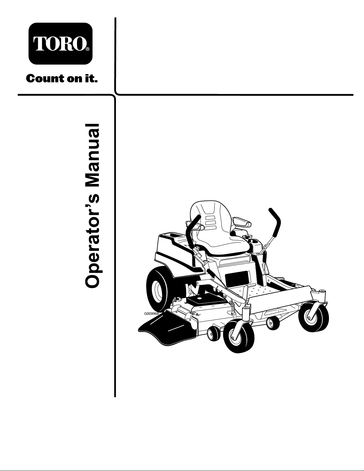
TITANZX4800Zero-Turn-Radius
RidingMower
ModelNo.74830—SerialNo.310000001andUp
ToregisteryourproductordownloadanOperator'sManualorPartsCatalogatnocharge,gotowww.T oro.com.OriginalInstructions(EN)
Page 2
Thismachineisaride-on,rotary-bladelawnmower
G009950
G010228
1
intendedtobeusedbyhomeownersinresidential
applications.Itisprimarilydesignedforcuttinggrass
onwell-maintainedlawns.Itisnotdesignedforcutting
brush,mowinggrassandothergrowthalongside
highways,orforagriculturaluses.
ThisproductcomplieswithallrelevantEuropean
directives,fordetailspleaseseetheseparateproduct
specicDeclarationofConformity(DOC)sheet.
WARNING
CALIFORNIA
Proposition65Warning
Theengineexhaustfromthisproduct
containschemicalsknowntotheStateof
Californiatocausecancer,birthdefects,
orotherreproductiveharm.
Important:Thisengineisnotequippedwitha
sparkarrestermufer.ItisaviolationofCalifornia
PublicResourceCodeSection4442touseoroperate
theengineonanyforest-covered,brush-covered,or
grass-coveredland.Otherstatesorfederalareas
mayhavesimilarlaws.
ThissparkignitionsystemcomplieswithCanadian
ICES-002
Wheneveryouneedservice,genuineToroparts,or
additionalinformation,contactanAuthorizedService
DealerorToroCustomerServiceandhavethemodel
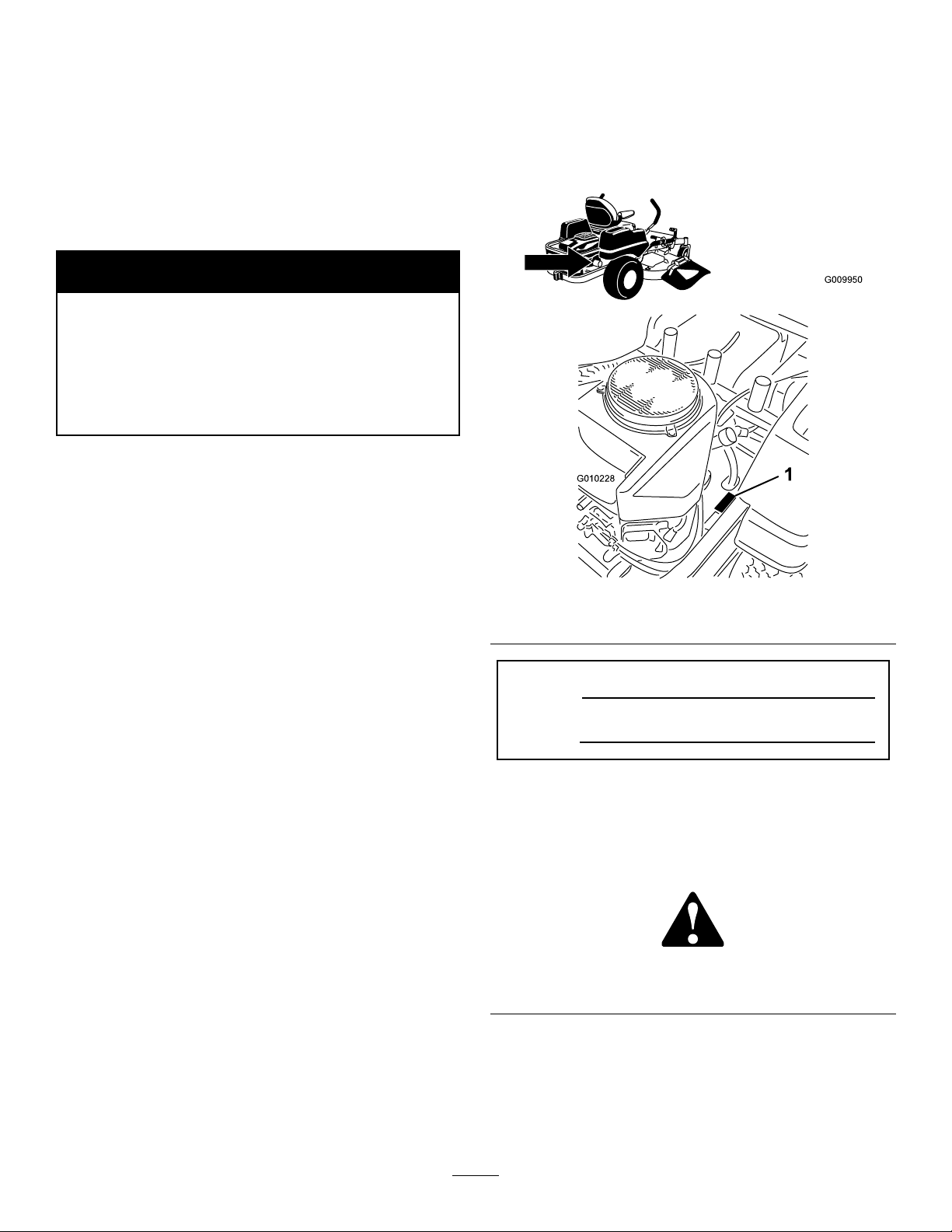
andserialnumbersofyourproductready .Figure1
identiesthelocationofthemodelandserialnumbers
ontheproduct.Writethenumbersinthespace
provided.
Figure1
1.Modelandserialnumberlocation
Theenclosed
Engine Owner’ s Man ual
issupplied
forinformationregardingtheUSEnvironmental
ProtectionAgency(EPA)andtheCalifornia
EmissionControlRegulationofemissionsystems,
maintenance,andwarranty.Replacementsmaybe
orderedthroughtheenginemanufacturer.
Formodelswithstatedenginehorsepower,thegross
horsepoweroftheenginewaslaboratoryratedbythe
enginemanufacturerinaccordancewithSAEJ1940.
Asconguredtomeetsafety,emission,andoperating
requirements,theactualenginehorsepoweronthisclass
oflawnmowerwillbesignicantlylower.
Introduction
Readthisinformationcarefullytolearnhowtooperate
andmaintainyourproductproperlyandtoavoidinjury
andproductdamage.Youareresponsibleforoperating
theproductproperlyandsafely.
YoumaycontactTorodirectlyatwww .T oro.comfor
productandaccessoryinformation,helpndinga
dealer,ortoregisteryourproduct.
ModelNo.
SerialNo.
Thismanualidentiespotentialhazardsandhas
safetymessagesidentiedbythesafetyalertsymbol
(Figure2),whichsignalsahazardthatmaycauseserious
injuryordeathifyoudonotfollowtherecommended
precautions.
Figure2
1.Safetyalertsymbol
Thismanualuses2otherwordstohighlightinformation.
Importantcallsattentiontospecialmechanical
informationandNoteemphasizesgeneralinformation
worthyofspecialattention.
©2009—TheT oro®Company
8111LyndaleAvenueSouth
Bloomington,MN55420
Contactusatwww.T oro.com.
2
PrintedintheUSA.
AllRightsReserved
Page 3

Contents
Introduction.................................................................2
Safety...........................................................................4
SafeOperatingPractices.......................................4
ToroRidingMowerSafety....................................6
SlopeIndicator.....................................................7
SafetyandInstructionalDecals.............................8
ProductOverview......................................................12
Controls.............................................................13
Operation...................................................................14
ThinkSafetyFirst...............................................14
AddingFuel.......................................................15
CheckingtheEngineOilLevel............................17
OperatingtheParkingBrake...............................17
OperatingtheThrottle.......................................17
OperatingtheChoke..........................................17
OperatingtheIgnitionSwitch.............................18
StartingandStoppingtheEngine........................18
OperatingtheMowerBladeControlSwitch
(PTO)............................................................19
TheSafetyInterlockSystem................................19
DrivingForwardorBackward.............................20
StoppingtheMachine.........................................21
AdjustingtheHeightofCut................................21
AdjustingtheAnti-ScalpRollers.........................22
PositioningtheSeat............................................23
ChangingtheSeatRideSuspension.....................23
AdjustingtheMotionControlLevers..................23
PushingtheMachinebyHand.............................24
UsingtheSideDischarge....................................25
OperatingTips...................................................25
Maintenance...............................................................27
RecommendedMaintenanceSchedule(s)................27
PremaintenanceProcedures....................................29
RaisingtheSeat..................................................29
Lubrication.............................................................29
GreasingtheBearings.........................................29
EngineMaintenance...............................................30
ServicingtheAirCleaner....................................30
ServicingtheEngineOil.....................................31
ServicingtheSparkPlug.....................................33
CleaningtheBlowerHousing..............................34
FuelSystemMaintenance.......................................34
ReplacingtheFuelFilter.....................................34
ElectricalSystemMaintenance................................35
ServicingtheBattery...........................................35
ServicingtheFuses.............................................36
DriveSystemMaintenance.....................................37
CheckingtheTirePressure.................................37
HydraulicSystemMaintenance...............................38
CheckingtheHydraulicOilLevel........................38
ChangingtheHydraulicSystemFilterand
Oil..................................................................38
MowerDeckMaintenance......................................40
ServicingtheCuttingBlades...............................40
MowerDeckLeveling.........................................42
InspectingtheBelts............................................44
ReplacingtheMowerBelt...................................44
RemovingtheMower.........................................44
InstallingtheMower...........................................45
ReplacingtheGrassDeector.............................45
Cleaning.................................................................47
WashingtheUndersideoftheMower..................47
WasteDisposal...................................................47
Storage.......................................................................48
CleaningandStorage..........................................48
Troubleshooting.........................................................49
Schematics.................................................................51
ConditionsandProductsCovered.......................52
OwnerResponsibilities.......................................52
ItemsandConditionsNotCovered.....................52
InstructionsforObtainingW arranty
Service...........................................................52
GeneralConditions............................................52
CountriesOtherthantheUnitedStatesor
Canada...........................................................52
3
Page 4

Safety
ThismachinemeetsorexceedstheB71.1-2003
specicationsoftheAmericanNationalStandards
Institute,ineffectatthetimeofproduction.
However,improperuseormaintenancebythe
operatororownercanresultininjury.Toreduce
thepotentialforinjury,complywiththesesafety
instructionsandalwayspayattentiontothe
safetyalertsymbol,whichmeansCAUTION,
WARNING,orDANGER-"personalsafety
instruction."Failuretocomplywiththeinstruction
mayresultinpersonalinjuryordeath.
•Neverleavearunningmachineunattended.Always
turnoffblades,setparkingbrake,stopengine,and
removekeybeforedismounting.
•Turnoffbladeswhennotmowing.Stoptheengine
andwaitforallpartstocometoacompletestop
beforecleaningthemachine,removingthegrass
catcheroruncloggingthedischargechute.
•Operatethemachineonlyindaylightorgood
articiallight.
•Donotoperatethemachinewhileunderthe
inuenceofalcoholordrugs.
•Watchfortrafcwhenoperatingnearorcrossing
roadways.
SafeOperatingPractices
ThefollowinginstructionsarefromANSIstandard
B71.1-2003.
Thisproductiscapableofamputatinghandsand
feetandthrowingobjects.Alwaysfollowallsafety
instructionstoavoidseriousinjuryordeath.
GeneralOperation
•Read,understand,andfollowallinstructionsin
theoperator’smanualandonthemachinebefore
starting.
•Donotplacehandsorfeetnearrotatingpartsor
underthemachine.Keepclearofthedischarge
openingatalltimes.
•Allowonlyresponsibleadultswhoarefamiliarwith
theinstructionstooperatethemachine.
•Cleartheareaofobjectssuchasrocks,toys,wire,
etc.,whichcouldbepickedupandthrownbythe
blade.
•Besuretheareaisclearofotherpeoplebefore
mowing.Stopthemachineifanyoneentersthearea.
•Nevercarrypassengers.
•Donotmowinreverseunlessabsolutelynecessary.
Alwayslookdownandbehindbeforeandwhile
backingup.
•Beawareofthemowerdischargedirectionanddo
notpointitatanyone.Avoiddischargingmaterial
againstawallorobstruction.Materialmayricochet
backtowardtheoperator.Stoptheblade(s)when
crossinggravelsurfaces.
•Donotoperatethemachinewithoutdeector,
dischargecoverorentiregrasscollectionsystemin
placeandworking.
•Bealert,slowdownandusecautionwhenmaking
turns.Lookbehindandtothesidebeforechanging
directions.
•Useextracarewhenloadingorunloadingthe
machineintoatrailerortruck.
•Alwaysweareyeprotectionwhenoperatingthe
mower.
•Dataindicatesthatoperators,age60yearsand
above,areinvolvedinalargepercentageofriding
mower-relatedinjuries.Theseoperatorsshould
evaluatetheirabilitytooperatetheridingmower
safelyenoughtoprotectthemselvesandothersfrom
seriousinjury.
•Alwaysfollowtherecommendationsforwheel
weightsorcounterweights.
•Lightningcancausesevereinjuryordeath.If
lightningisseenorthunderisheardinthearea,do
notoperatethemachine;seekshelter.
SlopeOperation
Slopesareamajorfactorrelatedtolossofcontroland
tip-overaccidents,whichcanresultinsevereinjuryor
death.Operationonallslopesrequiresextracaution.If
youcannotbackuptheslopeorifyoufeeluneasyonit,
donotmowit.
•Donotmowslopesgreaterthan15degrees.
•Watchforditches,holes,rocks,dips,andrisesthat
changetheoperatingangle,asroughterraincould
overturnthemachine.
•Choosealowgroundspeedsoyouwillnothaveto
stopwhileoperatingonaslope.
•Donotmowslopeswhengrassiswet.Slippery
conditionsreducetractionandcouldcausesliding
andlossofcontrol.
•Alwayskeepthewheelmotorsengagedwhengoing
downslopes.
•Reducespeedanduseextremecautiononslopes.
•Donotmakesuddenturnsorrapidspeedchanges.
4
Page 5

•Removeormarkobstaclessuchasrocks,treelimbs,
etc.fromthemowingarea.Tallgrasscanhide
obstacles.
•Avoidsuddenstartswhenmowinguphillbecause
themowermaytipbackwards.
•Beawarethatlossoftractionmayoccurgoing
downhill.Weighttransfertothefrontwheelsmay
causedrivewheelstoslipandcauselossofbraking
andsteering.
•Alwaysavoidsuddenstartingorstoppingona
slope.Iftireslosetraction,disengagethebladesand
proceedslowlyofftheslope.
•Useextremecarewithgrasscatchersorother
attachments.Thesecanchangethestabilityofthe
machineandcauselossofcontrol.
•Donottrytostabilizethemachinebyputtingyour
footontheground.
Towing
Ahitchkitisavailableforthismachineandcanbe
obtainedbycontactinganAuthorizedToroDealer.
Donottowwithoutrstinstallingthismanufacturer
approvedhitch.Thefollowingguidelinesapplywhen
towingwiththeapprovedhitchkitinstalled.
•Towonlywithamachinethathasahitchdesigned
fortowing.Donotattachtowedequipmentexcept
atthehitchpoint.
•Followthemanufacturer’srecommendationfor
weightlimitsfortowedequipmentandtowingon
slopes.
•Neverallowchildrenorothersinorontowed
equipment.
•Onslopes,theweightofthetowedequipmentmay
causelossoftractionandlossofcontrol.
•Travelslowlyandallowextradistancetostop.
•Donotmowneardrop-offs,ditches,steepbanks
orwater.Wheelsdroppingoveredgescancause
rollovers,whichmayresultinseriousinjury,death
ordrowning.
•Useawalkbehindmowerand/orahandtrimmer
neardrop-offs,ditches,steepbanksorwater.
Children
Tragicaccidentscanoccuriftheoperatorisnotalertto
thepresenceofchildren.Childrenareoftenattractedto
themachineandthemowingactivity.Neverassumethat
childrenwillremainwhereyoulastsawthem.
•Keepchildrenoutofthemowingareaandunder
thewatchfulcareofanotherresponsibleadult,not
theoperator.
•Bealertandturnthemachineoffifchildrenenter
thearea.
•Beforeandwhilebackingorchangingdirection,look
behind,down,andside-to-sideforsmallchildren.
•Nevercarrychildren,evenwiththebladesoff.They
mayfalloffandbeseriouslyinjuredorinterferewith
safemachineoperation.
•Childrenwhohavebeengivenridesinthepastmay
suddenlyappearinthemowingareaforanotherride
andberunoverorbackedoverbythemower.
•Neverallowchildrentooperatethemachine.
•Useextracarewhenapproachingblindcorners,
shrubs,trees,theendofafenceorotherobjectsthat
mayobscurevision.
Service
SafeHandlingofGasoline:
Toavoidpersonalinjuryorpropertydamage,useextra
carewhenhandlinggasolineandotherfuels.Theyare
ammableandthevaporsareexplosive.
•Extinguishallcigarettes,cigars,pipesandother
sourcesofignition.
•Useonlyanapprovedcontainer.
•Neverremovethegascaporaddfuelwhenthe
engineisrunning.Allowtheenginetocoolbefore
refueling.
•Neverrefuelthemachineindoors.
•Neverstorethemachineorfuelcontainerinside
wherethereisanopename,suchasnearawater
heaterorfurnace.
•Neverllcontainersinsideavehicleoronatruckor
trailerwithaplasticliner.Alwaysplacecontainerson
thegroundawayfromyourvehiclebeforelling.
•Removegas-poweredequipmentfromthetruck
ortrailerandrefuelitontheground.Ifthisisnot
possible,thenrefuelsuchequipmentwithaportable
container,ratherthanfromagasolinedispenser
nozzle.
•Keepthenozzleincontactwiththerimofthefuel
tankorcontaineropeningatalltimesuntilthefueling
iscomplete.Donotuseanozzlelock-opendevice.
•Iffuelisspilledonclothing,changeclothing
immediately.
•Neveroverllthefueltank.Replacegascapand
tightensecurely .
5
Page 6

GeneralService:
•Neveroperateamachineinsideaclosedarea.Engine
exhaustcontainscarbonmonoxide,whichisan
odorless,deadlypoisonthatcankillyou.
•Keepnutsandboltstight,especiallytheblade
attachmentbolts.Keepequipmentingood
condition.
•Nevertamperwithsafetydevices.Checktheir
properoperationregularly .
•Keepthemachinefreeofgrass,leaves,orother
debrisbuild-up.Cleanupoilorfuelspillagefuel
soakeddebris.Allowthemachinetocoolbefore
storing.
•Stopandinspecttheequipmentifyoustrikean
object.Repair,ifnecessary,beforerestarting.
•Nevermakeanyadjustmentsorrepairswiththe
enginerunning.
•Grasscatchercomponentsaresubjecttowear,
damageanddeterioration,whichcouldexpose
movingpartsorallowobjectstobethrown.
Frequentlycheckcomponentsandreplacewith
manufacturers’recommendedparts,whennecessary.
•Batterygasescanexplode.Keepcigarettes,sparks
andamesawayfrombattery.
•UseonlyToroapprovedattachments.W arrantymay
bevoidedifusedwithunapprovedattachments.
•Ifloadingthemachineontoatrailerortruck,usea
single,full-widthramponly.Therampangleshould
notexceed15degrees.
Note:Determinetheleftandrightsidesofthe
machinefromthenormaloperatingposition.
•Mowerbladesaresharpandcancut.Wrapthe
blade(s)orweargloves,anduseextracautionwhen
servicingthem.
•Checkforproperbrakeoperationfrequently.Adjust
andserviceasrequired.
•Maintainorreplacesafetyandinstructiondecalsas
necessary.
•UseonlygenuineTororeplacementpartstoensure
thatoriginalstandardsaremaintained.
ToroRidingMowerSafety
Thefollowinglistcontainssafetyinformationspecicto
Toroproductsorothersafetyinformationthatyoumust
knowthatisnotincludedintheANSIstandards.
•Stoptheengine,disconnectsparkplugwire(s)and
removekeybeforeperforminganyservice,repairs,
maintenanceoradjustments.
•Keephands,feet,hair,andlooseclothingawayfrom
attachmentdischargearea,undersideofmowerand
anymovingpartswhileengineisrunning.
•Donottouchequipmentorattachmentpartswhich
maybehotfromoperation.Allowtocoolbefore
attemptingtomaintain,adjustorservice.
•Batteryacidispoisonousandcancauseburns.Avoid
contactwithskin,eyes,andclothing.Protectyour
face,eyes,andclothingwhenworkingwithabattery.
6
Page 7
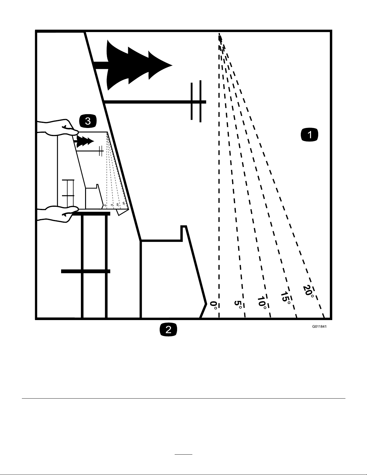
SlopeIndicator
G011841
Figure3
Thispagemaybecopiedforpersonaluse.
1.Themaximumslopeyoucansafelyoperatethemachineonis15degrees.Usetheslopecharttodeterminethedegreeofslope
ofhillsbeforeoperating.Donotoperatethismachineonaslopegreaterthan15degrees.Foldalongtheappropriateline
tomatchtherecommendedslope.
2.Alignthisedgewithaverticalsurface,atree,building,fencepole,etc.
3.Exampleofhowtocompareslopewithfoldededge.
7
Page 8
SafetyandInstructional
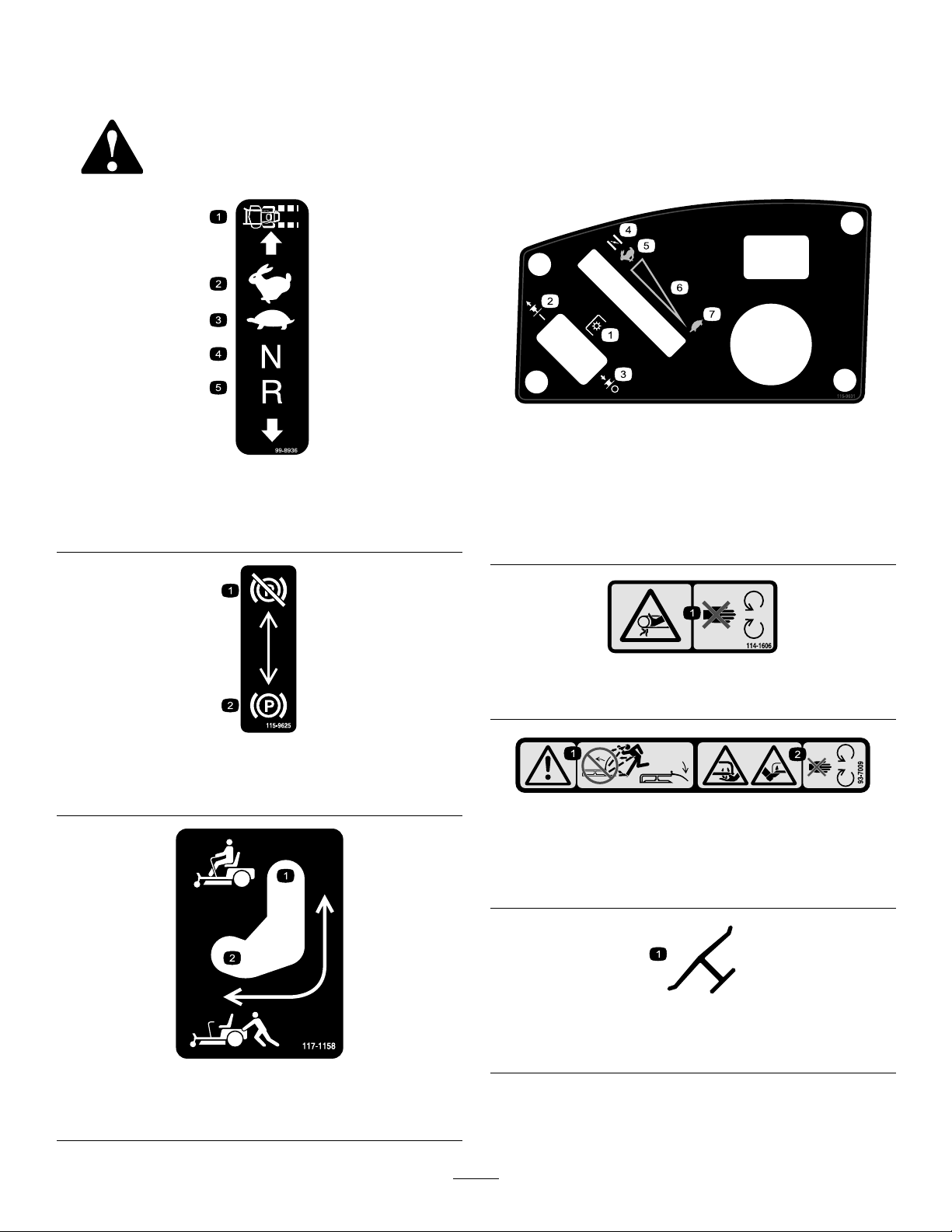
Decals
Safetydecalsandinstructionsareeasilyvisibletotheoperatorandarelocatednearanyareaof
potentialdanger.Replaceanydecalthatisdamagedorlost.
1.Machinespeed4.Neutral
2.Fast5.Reverse
3.Slow
115-9631
1.Powertake-off(PTO),
99-8936
Bladecontrolswitchon
somemodels
2.Bladecontrolswitch—On6.Continuousvariable
3.Bladecontrolswitch—Off7.Slow
4.Choke
5.Fast
setting
1.Parking
brake—disengaged
1.Bypassleverpositionfor
operatingthemachine
114-1606
1.Entanglementhazard,belt—keepallguardsinplace.
115-9625
2.Parkingbrake—engaged
93-7009
1.Warning—don’toperatethemowerwiththedeectorupor
removed;keepthedeectorinplace.
2.Cutting/dismembermenthazardofhandorfoot,mower
blade—stayawayfrommovingparts.
Manufacturer’sMark
1.Indicatesthebladeisidentiedasapartfromtheoriginal
machinemanufacturer.
117-1158
2.Bypassleverpositionfor
pushingthemachine
8
Page 9
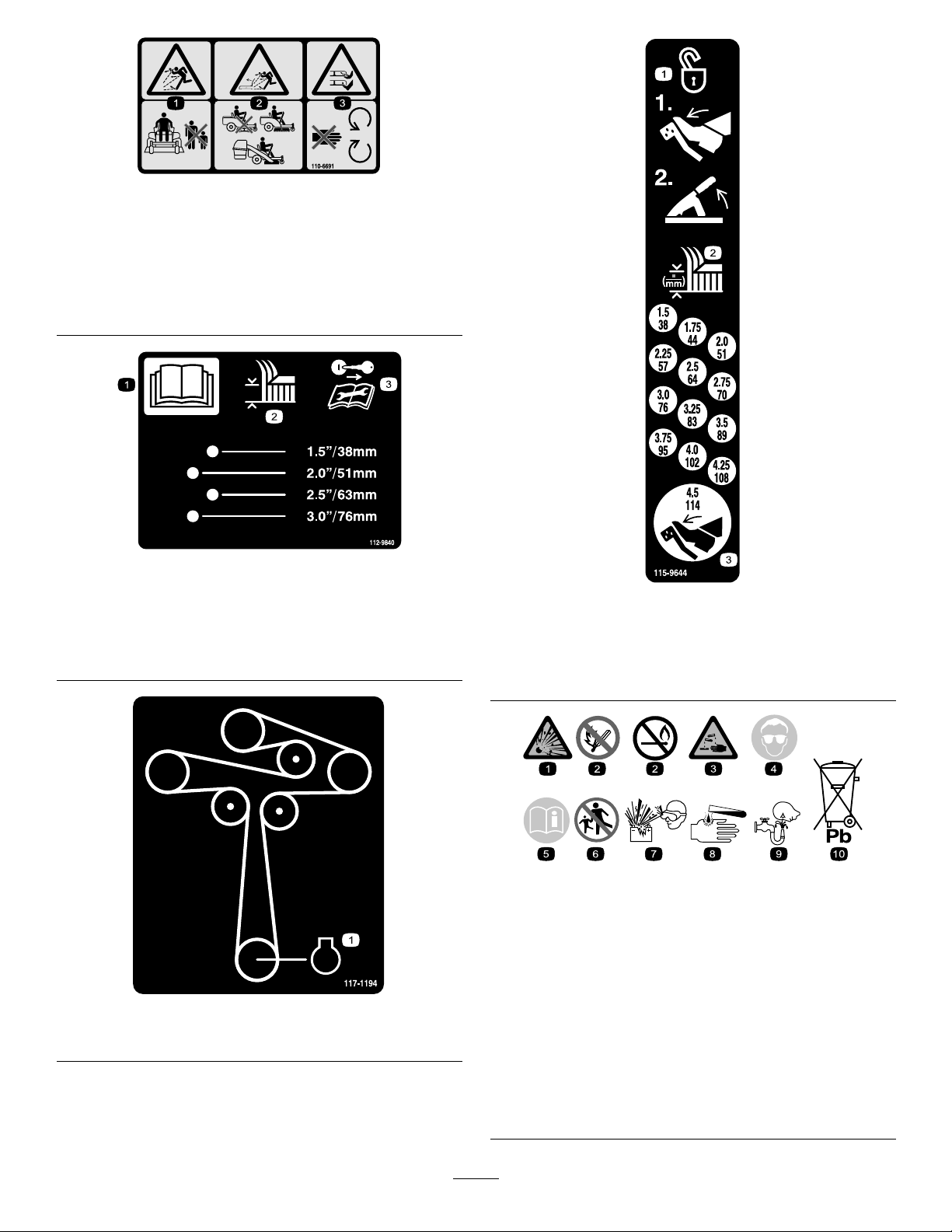
110-6691
1.Thrownobjecthazard—keepbystandersasafedistance
fromthemachine.
2.Thrownobjecthazard,mower—donotoperatewithoutthe
deector,dischargecover,orgrasscollectionsystemin
place.
3.Cutting/dismembermentofhandorfoot—stayawayfrom
movingparts.
112-9840
1.ReadtheOperator’s
Manual.
2.Heightofcut
3.Removetheignitionkey
andreadtheinstructions
beforeservicingor
performingmaintenance.
115-9644
1.Pressthepedalandlifttheheightofcutlevertounlock
thedeckposition.
2.Heightofcut
3.Pressthepedaltomovethedecktothetransportposition
BatterySymbols
Someorallofthesesymbolsareonyourbattery
1.Explosionhazard
2.Nore,opename,or
smoking.
117-1194
1.Engine
3.Causticliquid/chemical
burnhazard
4.Weareyeprotection9.Flusheyesimmediately
5.ReadtheOperator’s
Manual.
6.Keepbystandersasafe
distancefromthebattery.
7.Weareyeprotection;
explosivegasescan
causeblindnessandother
injuries
8.Batteryacidcancause
blindnessorsevereburns.
withwaterandgetmedical
helpfast.
10.Containslead;donot
discard.
9
Page 10
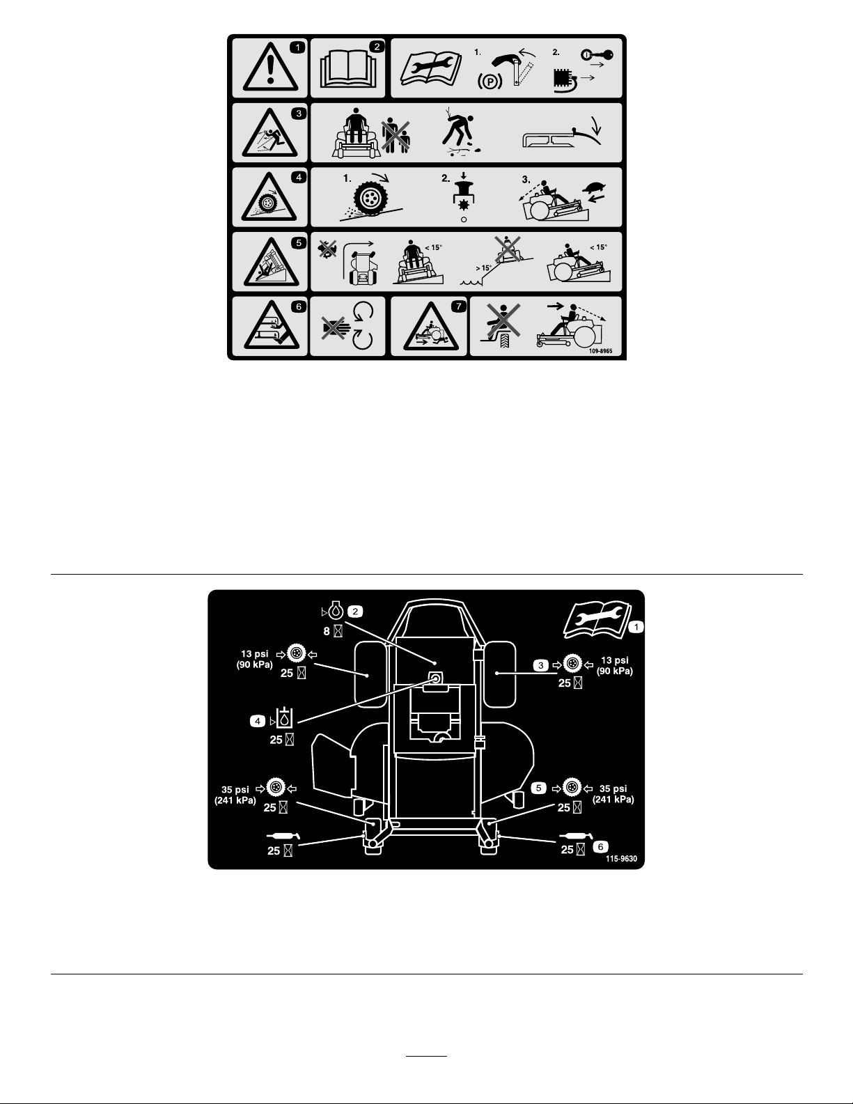
109-8965
1.Warning–readtheOperator’sManual.
2.Readtheinstructionsbeforeservicingorperformingmaintenance;applyparkingbrake,removetheignitionkeyanddisconnect
thesparkplugwire.
3.Thrownobjecthazard—keepbystandersasafedistancefromthemachine,pickupdebrisbeforeoperating,keepthedischarge
deectorinplace.
4.Lossoftraction/controlhazard,slopes–lossoftraction/controlonslope,disengagethebladecontrolswitch(PTO),proceed
offtheslopeslowly.
5.Tippinghazard–avoidsuddenandsharpturnswhileonslopes,onlymowacrossslopeslessthan15degrees,keepasafe
distancefromwater,andonlymowupanddownslopeslessthan15degrees.
6.Cutting/dismembermenthazardofhandorfoot,mowerblade–stayawayfrommovingparts.
7.Crushing/dismembermenthazardofbystanders,reversing–DoNotcarrypassengers,lookbehindanddownwhenreversing.
115-9630
1.ReadtheOperator’sManualbeforeperformingany
maintenance.
2.Checktheengineoilevery8hours5.Checkthecasterwheeltirepressureevery25hours
3.Checkthedrivewheeltirepressureevery25hours
4.Checkthehydraulicoilevery25hours
6.Lubricatethecasterwheelevery25hours
10
Page 11

1.Fuel2.Full
117–7490
3.Half
4.Empty
11
Page 12

ProductOverview
G010001
1
2
3
4
5
6
7
8
9
10
G010009
1
2
3
4
5
6
Figure4
1.Motioncontrollevers4.Fuelgauge7.Anti-scalproller
2.Operatorseat
3.Parkingbrake6.Frontcasterwheel
5.Footrest
8.Deector
9.Footpedaldeckliftand
height-of-cut
10.Controlpanel
Figure5
1.Gastankcap
2.MowerDeck4.Drivewheel6.Engine
3.Washoutport5.Engineguard
12
Page 13
Controls
G009918
1
2
3
4
G010016
G010077
1
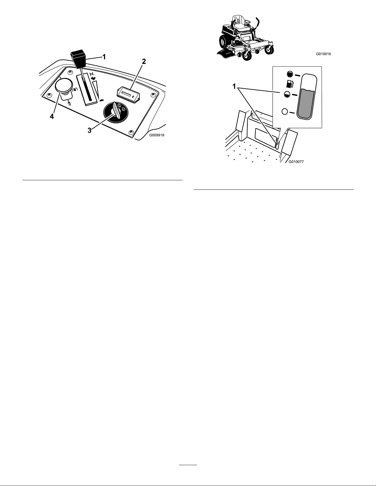
Becomefamiliarwithallthecontrolsbeforeyoustart
theengineandoperatethemachine(Figure6).
Figure6
1.Throttleandchokecontrol
2.Hourmeter5.Fuses
3.Ignitionswitch
IgnitionSwitch
4.Bladecontrolswitch(PTO)
Figure7
1.Fuelgaugewindow
Theignitionswitchhasthreepositions:Start,Run
andOff.ThekeywillturntoStartandmovebackto
Runuponrelease.TurningthekeytotheOffposition
willstoptheengine;however,alwaysremovethekey
whenleavingthemachinetopreventtheenginefrom
accidentallystarting(
Figure6).
Throttle/ChokeControl
Thethrottleandchokeiscombinedintoonecontrol
lever.ThethrottlecontrolisvariablebetweenFastand
Slow.Engagethechokebymovingtheleverpastthe
Fastsettinguntilitstops(
Figure6).
BladeControlSwitch(PowerTake-Off)
Thebladecontrolswitch,representedbyapower
take-off(PTO)symbol,engagesanddisengagespower
tothemowerblades(Figure6).
HourMeter
Thehourmeterrecordsthenumberofhourstheblades
haveoperated.Itoperateswhenthebladecontrol
switch(PTO)isengaged.Usethesetimesforscheduling
regularmaintenance(Figure6).
FuelGauge
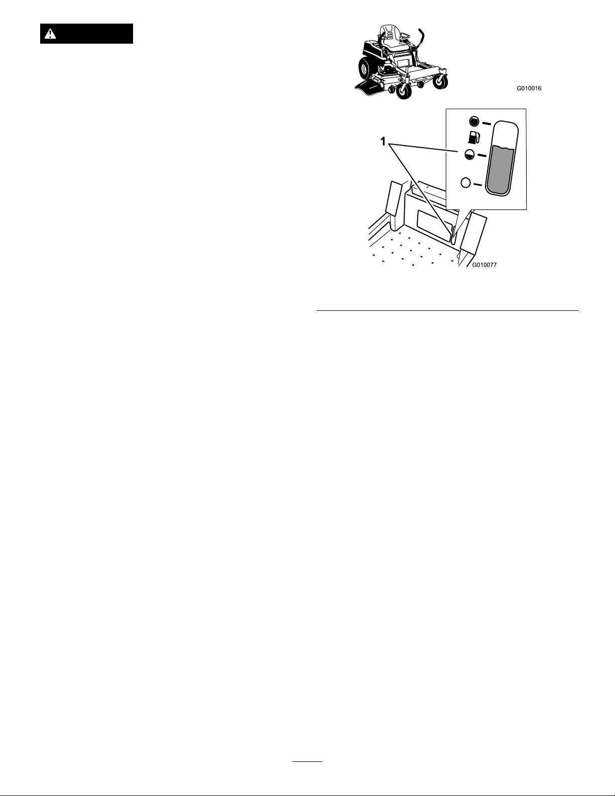
Thefuelwindowlocatedbelowtheoperatorposition
canbeusedtoverifythelevelofgasolineinthetank
(Figure7).
MotionControlLevers
Themotioncontrolleversarespeedsensitivecontrols
ofindependentwheelmotors.Movingaleverforward
orbackwardturnsthewheelonthesamesideforward
orinreverse;wheelspeedisproportionaltotheamount
theleverismoved.Movethecontrolleversoutward
fromthecentertotheneutrallockpositionandexitthe
machine(
Figure4).Alwayspositionthemotioncontrol
leversintotheneutrallockpositionwhenyoustopthe
machineorleaveitunattended.
NeutralLockPosition
Theneutrallockpositionisusedwiththesafetyinterlock
systemtoengageanddisengagethemowerbladesand
todetermineneutralposition.
FootPedalDeckLiftSystem
Thefootpedaldeckliftsystemallowstheoperator
tolowerandraisethedeckfromtheseatedposition.
Theoperatorcanusethefootpedaltoliftthedeck
brieytoavoidobstaclesorlockthedeckinthehighest
height-of-cutortransportposition(Figure4).
Height-of-CutLever
Theheight-of-cutleverworkswiththefootpedalto
lockthedeckinaspeciccuttingheight.Onlyadjustthe
heightofcutwhilemachineisnotmoving(Figure4).
13
Page 14

Attachments/Accessories
AselectionofToroapprovedattachmentsand
accessoriesareavailableforusewiththemachineto
enhanceandexpanditscapabilities.Contactyour
AuthorizedServiceDealerorDistributororgoto
www.Toro.comforalistofallapprovedattachments
andaccessories.
Operation
Note:Determinetheleftandrightsidesofthe
machinefromthenormaloperatingposition.
ThinkSafetyFirst
Pleasecarefullyreadallofthesafetyinstructionsand
decalsinthesafetysection.Knowingthisinformation
couldhelpyou,yourfamily,petsorbystandersavoid
injury.
DANGER
Mowingonwetgrassorsteepslopescancause
slidingandlossofcontrol.
Wheelsdroppingoveredgescancauserollovers,
whichmayresultinseriousinjury,deathor
drowning.
Alossoftractionisalossofsteeringcontrol.
Toavoidlossofcontrolandpossibilityofrollover:
•Donotmowneardrop-offsornearwater.
•Donotmowslopesgreaterthan15degrees.
•Reducespeedanduseextremecautionon
slopes.
•Whenmowingslopes,graduallyworkfrom
lowertohigherareasontheincline.
•Avoidsuddenturnsorrapidspeedchanges.
•Turnup,intoaninclinewhenchanging
directionsonslopes.Turningdowntheslope
reducestraction.
•Attachmentschangethehandling
characteristicsofthemachine.Use
extracautionwhenusingattachmentswiththe
machine.
14
Page 15
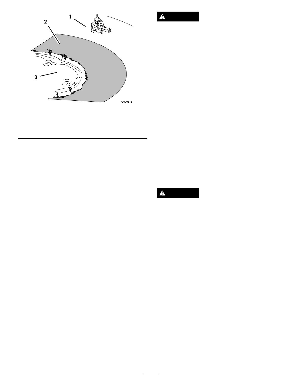
Figure8
1.SafeZone-usethemachinehere
2.Usewalkbehindmowerand/orhandtrimmerneardrop-offs
andwater.
3.Water
AddingFuel
Useunleadedregulargasolinesuitableforautomotive
use(85pumpoctaneminimum).Leadedregular
gasolinemaybeusedifunleadedregularisnotavailable.
DANGER
Incertainconditions,gasolineisextremely
ammableandhighlyexplosive.Areorexplosion
fromgasolinecanburnyouandothersandcan
damageproperty.
•Fillthefueltankoutdoors,inanopenarea,
whentheengineiscold.Wipeupanygasoline
thatspills.
•Neverllthefueltankinsideanenclosedtrailer.
•Donotllthefueltankcompletelyfull.Add
gasolinetothefueltankuntilthelevelis1/4to
1/2inch(6to13mm)belowthebottomofthe
llerneck.Thisemptyspaceinthetankallows
gasolinetoexpand.
•Neversmokewhenhandlinggasoline,andstay
awayfromanopenameorwheregasoline
fumesmaybeignitedbyaspark.
•Storegasolineinanapprovedcontainerand
keepitoutofthereachofchildren.Neverbuy
morethana30-daysupplyofgasoline.
•Donotoperatewithoutentireexhaustsystem
inplaceandinproperworkingcondition.
Important:Neverusemethanol,gasoline
containingmethanol,orgasoholcontainingmore
than10%ethanolbecausethefuelsystemcouldbe
damaged.Donotmixoilwithgasoline.
DANGER
Incertainconditionsduringfueling,static
electricitycanbereleasedcausingasparkwhich
canignitethegasolinevapors.Areorexplosion
fromgasolinecanburnyouandothersandcan
damageproperty.
•Alwaysplacegasolinecontainersontheground
awayfromyourvehiclebeforelling.
•Donotllgasolinecontainersinsideavehicle
oronatruckortrailerbedbecauseinterior
carpetsorplastictruckbedlinersmayinsulate
thecontainerandslowthelossofanystatic
charge.
•Whenpractical,removegas-powered
equipmentfromthetruckortrailerandrefuel
theequipmentwithitswheelsontheground.
•Ifthisisnotpossible,thenrefuelsuch
equipmentonatruckortrailerfromaportable
container,ratherthanfromagasolinedispenser
nozzle.
•Ifagasolinedispensernozzlemustbeused,
keepthenozzleincontactwiththerimofthe
fueltankorcontaineropeningatalltimesuntil
fuelingiscomplete.
15
Page 16
WARNING
G010016
G010077
1
Gasolineisharmfulorfatalifswallowed.
Long-termexposuretovaporscancauseserious
injuryandillness.
•Avoidprolongedbreathingofvapors.
•Keepfaceawayfromnozzleandgastankor
conditioneropening .
•Keepgasawayfromeyesandskin.
UsingStabilizer/Conditioner
Useafuelstabilizer/conditionerinthemachineto
providethefollowingbenets:
•Keepsgasolinefreshduringstorageof90daysor
less.Forlongerstorageitisrecommendedthatthe
fueltankbedrained.
•Cleanstheenginewhileitruns
•Eliminatesgum-likevarnishbuildupinthefuel
system,whichcauseshardstarting
Figure9
1.Fuelgaugewindow
Important:Donotusefueladditivescontaining
methanolorethanol.
Addthecorrectamountofgasstabilizer/conditioner
tothegas.
Note:Afuelstabilizer/conditionerismosteffective
whenmixedwithfreshgasoline.Tominimizethe
chanceofvarnishdepositsinthefuelsystem,usefuel
stabilizeratalltimes.
Gasoline/Alcoholblends
Gasohol(upto10percentethylalcohol,90percent
unleadedgasolinebyvolume)isapprovedforfueluse
bytheenginemanufacturer.Othergasoline/alcohol
blends,suchasE85,arenotapproved.
Gasoline/Etherblends
MethylTertiaryButylEther(MTBE)andunleaded
gasolineblends(uptoamaximumof15percentMTBE
byvolume)areapprovedforfuelusebytheengine
manufacturer.Othergasoline/etherblendsarenot
approved.
FillingtheFuelTank
Note:Donotllthefueltankcompletelyfull,thiswill
allowgasolinetoexpand.
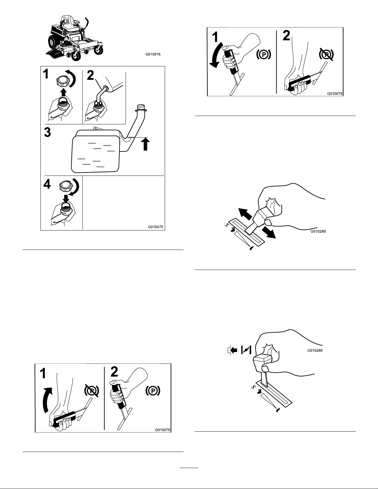
1.Shuttheengineoffandsettheparkingbrake.
2.Cleanaroundthefueltankcap.
3.Fillthefueltanktothebottomoftheller
Figure10.
neck
FuelGauge
Usethefuelwindowbelowtheoperatortoverifythe
levelofgasolinebeforellingthetank(Figure9).
16
Page 17
G010016
G010475
1
2
4
3
G010078
1
2
ReleasingtheParkingBrake
G010079
1
2
G010289
G010288
Figure12
OperatingtheThrottle
ThethrottlecontrolcanbemovedbetweenFastand
Slowpositions(Figure13).
Alwaysusethefastpositionwhenturningonthe
mowerdeckwiththebladecontrolswitch(PTO).
Figure10
CheckingtheEngineOilLevel
Beforeyoustarttheengineandusethemachine,check
theoillevelintheenginecrankcase;refertoChecking
theEngineOilLevel.
OperatingtheParkingBrake
Alwayssettheparkingbrakewhenyoustopthe
machineorleaveitunattended.
SettingtheParkingBrake
Figure13
OperatingtheChoke
Iftheengineiscold,usethechoketostarttheengine.
Engagethechokebymovingthethrottleleverpastthe
Fastsettinguntilitstops(Figure14).
Figure11
Figure14
Movethethrottleleverbacktodisengagethechoke
aftertheenginehasstarted.
17
Page 18
OperatingtheIgnitionSwitch
START
RUN
STOP
G008947
G010080
2
3
4
5
1
START
RUN
STOP
G008947
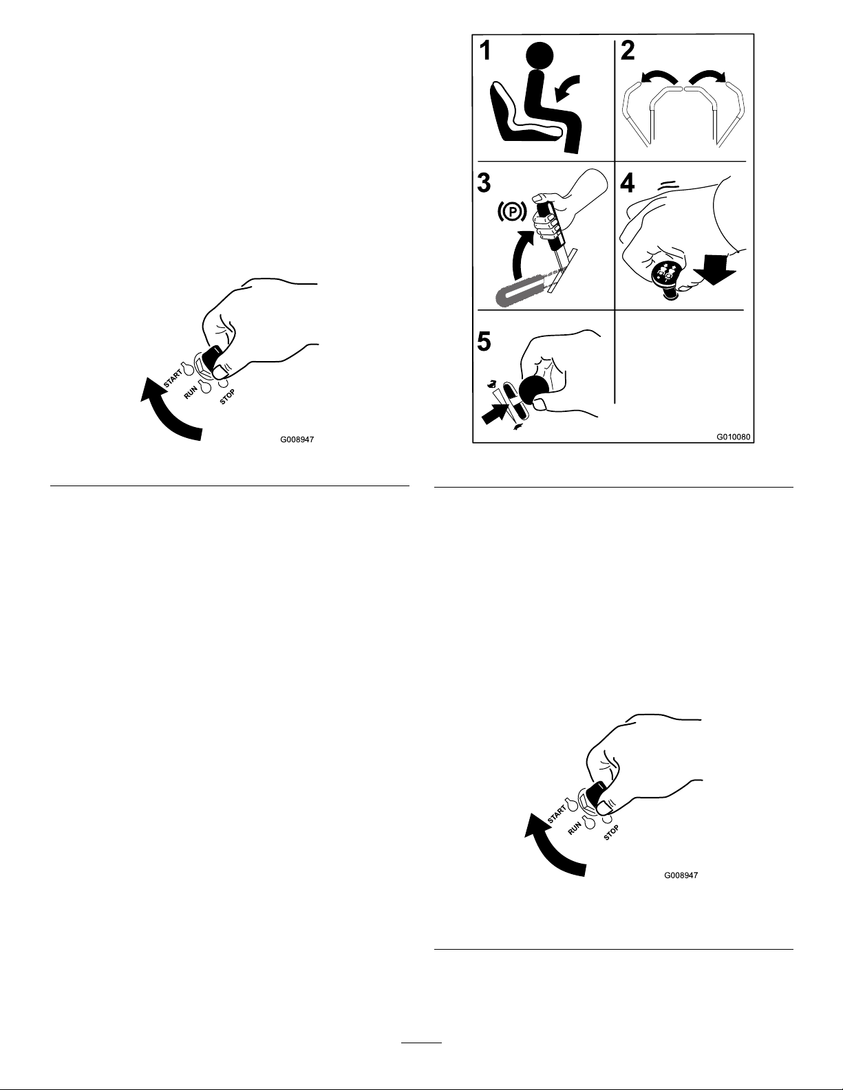
1.TurntheignitionkeytotheStartposition
(Figure15).Whentheenginesstarts,releasethekey.
Important:Donotengagestarterformore
than5secondsatatime.Iftheenginefails
tostartallowa15secondcool-downperiod
betweenattempts.Failuretofollowthese
instructionscanburnoutthestartermotor.
Note:Additionalstartingcyclesmayberequired
whenstartingtheengineforthersttimeafterthe
fuelsystemhasbeenwithoutfuelcompletely.
Figure15
2.Turntheignitionkeytostoptostoptheengine.
StartingandStoppingthe
Engine
StartingtheEngine
1.Sitdownontheseat(Figure16).
2.Movethemotioncontrolsoutwardtotheneutral
lockposition(
3.Settheparkingbrake(Figure16);refertoSetting
theParkingBrake.
4.Movethebladecontrolswitch(PTO)totheOff
position(
5.MovethethrottlelevertoChokebeforestarting
acoldengine.
Figure16).
Figure16).
Figure16
6.TurntheignitionkeytotheStartposition
(Figure15).Whentheenginesstarts,releasethekey.
Important:Donotengagestarterformore
than5secondsatatime.Iftheenginefails
tostartallowa15secondcool-downperiod
betweenattempts.Failuretofollowthese
instructionscanburnoutthestartermotor.
Note:Additionalstartingcyclesmayberequired
whenstartingtheengineforthersttimeafterthe
fuelsystemhasbeenwithoutfuelcompletely.
Note:Awarmorhotenginemaynotrequire
choking.
Figure17
1.Off3.Start
2.Run
18
Page 19
StoppingtheEngine
ST
ART
RUN
ST
OP
G010081
2
3
4
5
1
G008945
G009174
CAUTION
Childrenorbystandersmaybeinjuredifthey
moveorattempttooperatethetractorwhileitis
unattended.
Alwaysremovetheignitionkeyandsettheparking
brakewhenleavingthemachineunattended,even
ifjustforafewminutes.
Figure19
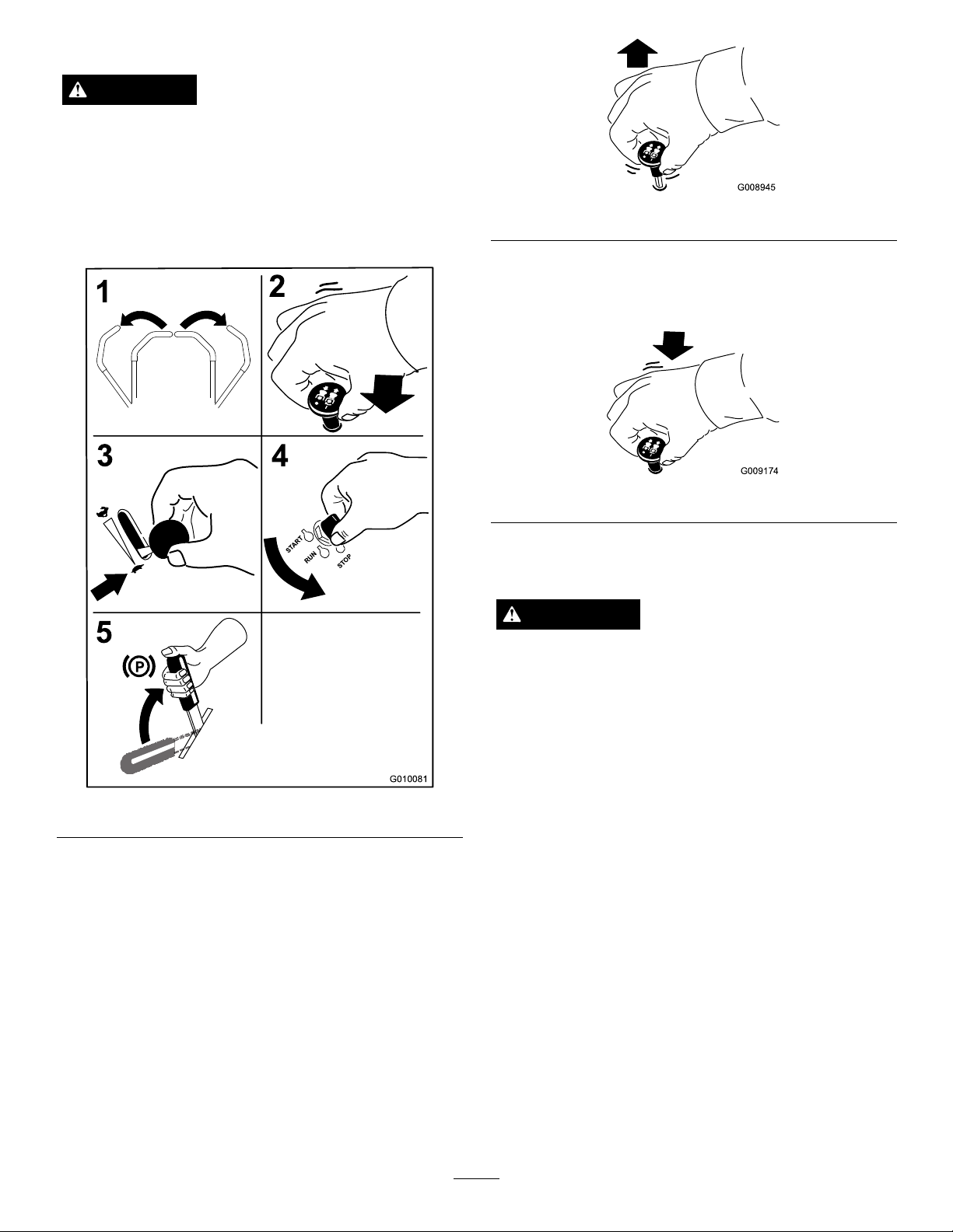
DisengagingtheBladeControlSwitch
(PTO)
Figure20
TheSafetyInterlockSystem
WARNING
Figure18
OperatingtheMowerBlade
ControlSwitch(PTO)
Thebladecontrolswitch(PTO)startsandstopsthe
mowerbladesandanypoweredattachments.
EngagingtheBladeControlSwitch
(PTO)
Note:Engagingthebladecontrolswitch(PTO)with
thethrottlepositionathalforlesswillcauseexcessive
weartothedrivebelts.
Ifsafetyinterlockswitchesaredisconnectedor
damagedthemachinecouldoperateunexpectedly
causingpersonalinjury.
•Donottamperwiththeinterlockswitches.
•Checktheoperationoftheinterlockswitches
dailyandreplaceanydamagedswitchesbefore
operatingthemachine.
UnderstandingtheSafetyInterlock
System
Thesafetyinterlocksystemisdesignedtopreventthe
enginefromstartingunless:
•Theparkingbrakeisengaged.
•Thebladesaredisengaged.
•Themotioncontrolleversareintheneutrallock
position.
Thesafetyinterlocksystemalsoisdesignedtostopthe
enginewhenthecontrolleversareoutoftheneutral
lockpositionwiththeparkingbrakeonorifyourise
fromtheseatwhenthebladesareengaged.
19
Page 20
TestingtheSafetyInterlockSystem
Testthesafetyinterlocksystembeforeyouusethe
machineeachtime.Ifthesafetysystemdoesnot
operateasdescribedbelow,haveanAuthorizedService
Dealerrepairthesafetysystemimmediately .
1.Whilesittingontheseat,engagetheparkingbrake
andmovethebladecontrolswitchtoOn.Try
startingtheengine;theengineshouldnotcrank.
2.Whilesittingontheseat,engagetheparkingbrake
andmovethebladecontrolswitchtoOff.Move
eithermotioncontrollever(forwardorreverse).
Trystartingtheengine;theengineshouldnotcrank.
Repeatwiththeothermotioncontrollever.
3.Whilesittingontheseat,engagetheparkingbrake,
movethebladecontrolswitchtoOff,andlockthe
motioncontrolleversinneutral.Starttheengine.
Whiletheengineisrunning,releasetheparking
brake,engagethebladecontrolswitch,andrise
slightlyfromtheseat;theengineshouldstop.
4.Whilesittingontheseat,engagetheparkingbrake,
movethebladecontrolswitchtoOff,andlockthe
motioncontrolleversinneutral.Starttheengine.
Whiletheengineisrunning,centerthemotion
controlsandmove(forwardorreverse);theengine
shouldstop.
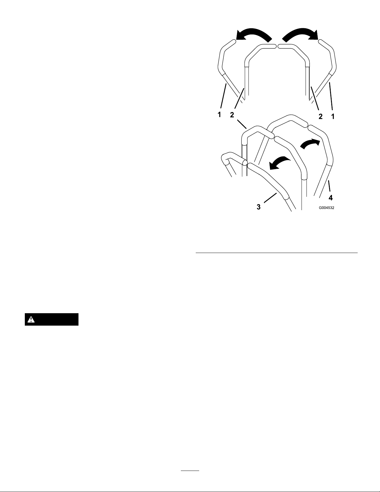
UsingtheMotionControlLevers
Figure21
1.Motioncontrol
lever-neutrallockposition
2.Center,unlockedposition
3.Forward
4.Backward
DrivingForwardorBackward
Thethrottlecontrolregulatestheenginespeedas
measuredinrpm(revolutionsperminute).Place
thethrottlecontrolinthefastpositionforbest
performance.Alwaysoperateinthefullthrottle
positionwhenmowing.
CAUTION
Machinecanspinveryrapidly.Operatormaylose
controlofmachineandcausepersonalinjuryor
damagetomachine.
•Usecautionwhenmakingturns.
•Slowthemachinedownbeforemakingsharp
turns.
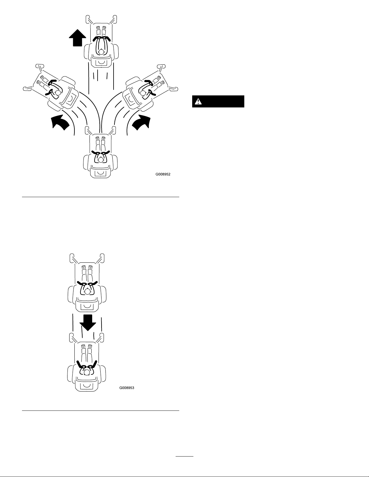
DrivingForward
Note:Theenginewillkillifthetractioncontrollevers
aremovedwiththeparkingbrakeengaged.
1.Releasetheparkingbrake;refertoReleasingthe
ParkingBrakeinOperation.
2.Movetheleverstothecenter,unlockedposition.
3.Togoforward,slowlypushthemotioncontrol
leversforward(
Figure22).
20
Page 21
G008952
G008953
StoppingtheMachine
Tostopthemachine,movethetractioncontrollevers
toneutralandmovetolockedposition,disengagethe
bladecontrolswitch(PTO),andturntheignitionkey
tooff.
Settheparkingbrakewhenyouleavethemachine;refer
toSettingtheParkingBrake.Remembertoremovethe
keyfromtheignitionswitch.
CAUTION
Childrenorbystandersmaybeinjuredifthey
moveorattempttooperatethetractorwhileitis
unattended.
Alwaysremovetheignitionkeyandsettheparking
brakewhenleavingthemachineunattended,even
ifjustforafewminutes.
Figure22
DrivingBackward
1.Movetheleverstothecenter,unlockedposition.
2.Togobackward,slowlypullthemotioncontrol
leversrearward(
Figure23).
AdjustingtheHeightofCut
Themachineisequippedwithafootpedaldecklift
system.Theoperatorcanusethefootpedaltolift
thedeckbrieytoavoidobstaclesorlockthedeckin
thehighestheight-of-cutortransportposition.The
operatorcanusetheheightofcutleverwiththefoot
pedaltolockthedeckinaspeciccuttingheight.
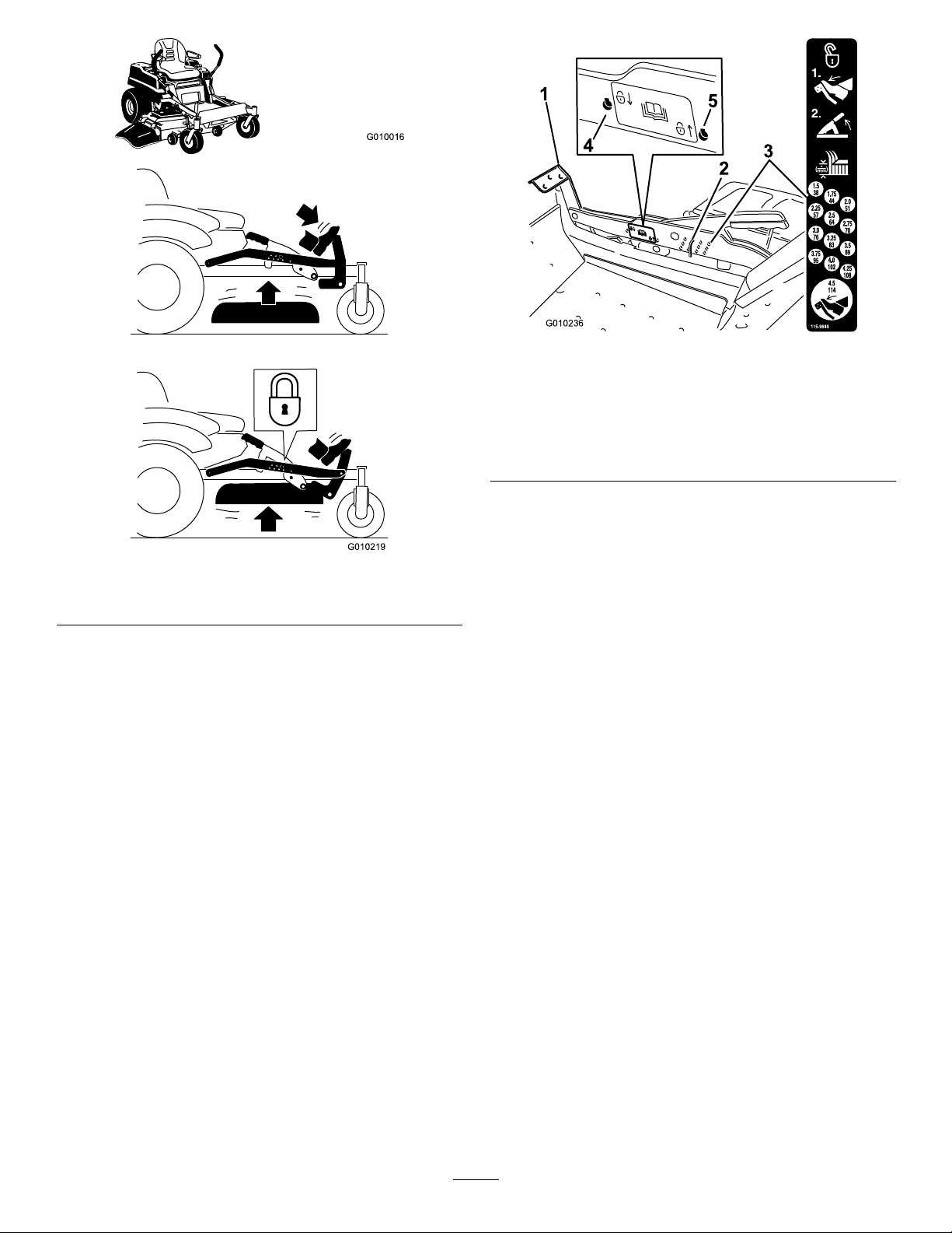
UsingtheFootPedalDeckLiftSystem
Pressthepedaldowntoraisethedeck;continueto
pressthepedaluntilthedeckislockedinthetransport
positionFigure24.Pushonthedeckliftpedalwith
yourfootandraisetheheight-of-cutleverslightlyto
disengagethetransportlock.
Figure23
21
Page 22
G010016
G010219
G010236
1
2
3
4
5
1.Deckliftpedal
2.Cutheightpin
3.Height-of-cutpositions
UsingtheLockPositions
Figure25
4.Lockposition.lowest
height-of-cut(useonlyfor
deckremoval)
5.Lockposition.transport
position
Figure24
TransportLockPosition
Thedeckcanbelockedinthehighestheight-of-cutor
transportpositionorthelowestheight-of-cutposition.
1.Pushonthedeckliftpedalwithyourfootandraise
themowerdecktothetransportposition(also
the4.5inch(114mm)cuttingheightposition)
Figure25).
AdjustingtheHeight-of-Cut
(
2.Removethepinfromtheheight-of-cutbracket
Theheight-of-cutcanbeadjustedfrom1-1/2to
(Figure25).
4-1/2inch(38to114mm)in1/4inch(6mm)
incrementsbyrelocatingtheclevispinintodifferent
holelocations.
1.Pushonthedeckliftpedalwithyourfootandraise
themowerdecktothetransportposition(also
the4-1/2inch(114mm)cuttingheightposition)
Figure25).
(
2.Toadjust,removethepinfromtheheight-of-cut
bracket(Figure25).
3.Selectaholeintheheight-of-cutsystem
correspondingtotheheight-of-cutdesiredand,
insertthepin(Figure25).
4.Pushonthedeckliftpedalwithyourfootandraise
theheight-of-cutleverslightlytodisengagethe
transportlock.Lowerthedeckslowlyuntilthepin
makescontactwiththelever.
3.Selectaholeonthelockdecalandinsertthepin
(Figure25).
4.Pushonthedeckliftpedalwithyourfootandraise
theheight-of-cutleverslightlytodisengagethe
transportlock.Lowerthedecktoslowlyuntilthe
pinmakescontactwiththelever.
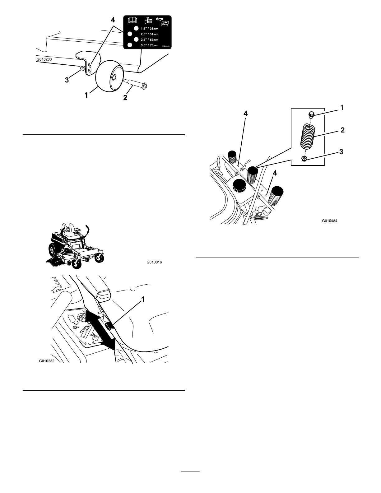
AdjustingtheAnti-Scalp
Rollers
Wheneveryouchangetheheight-of-cut,itis
recommendedtoadjusttheheightoftheanti-scalp
rollers.
1.Disengagethebladecontrolswitch(PTO),move
themotioncontrolleverstotheneutrallock
positionandsettheparkingbrake.
2.Stoptheengine,removethekey,andwaitforall
movingpartstostopbeforeleavingtheoperating
position.
22
Page 23
G010233
1
2
3
4
Figure26
G010016
G010232
1
G010484
4
4
1.Anti-scalproller3.FlangeNut
2.Bolt4.Holespacing
PositioningtheSeat
Theseatcanmoveforwardandbackward.Positionthe
seatwhereyouhavethebestcontrolofthemachine
andaremostcomfortable.
Whilesittingintheoperator’ sposition,raisetheseat
adjustmentleverslightlyandmovetheseatforwardor
backwardtothedesiredposition(
Figure27).
ChangingtheSeatRide
Suspension
Thenumberofseatspringscanbechangedto
maximizeridercomfort.Morespringsshouldbeused
withheavieroperatorsandonroughterrain.Fewer
springsshouldbeusedwithlighteroperatorsandwhen
mowingsmooth,wellestablishedlawns.Alwayskeep
thenumberofspringsontheleftandrightsidethe
samewhenaddingandremovingsprings.
1.Adjustmentlever
Figure28
1.Bolt3.Nut
2.Spring
4.Additionalmountingholes
Uptovespringscanbesecuredtotheseatsupport
withanutandbolt,seeFigure28.
RefertoyourPartsManualforspringandhardware
partnumbers.
AdjustingtheMotionControl
Levers
AdjustingtheHeight
Figure27
Themotioncontrolleverscanbeadjustedhigheror
lowerformaximumoperatorcomfort.
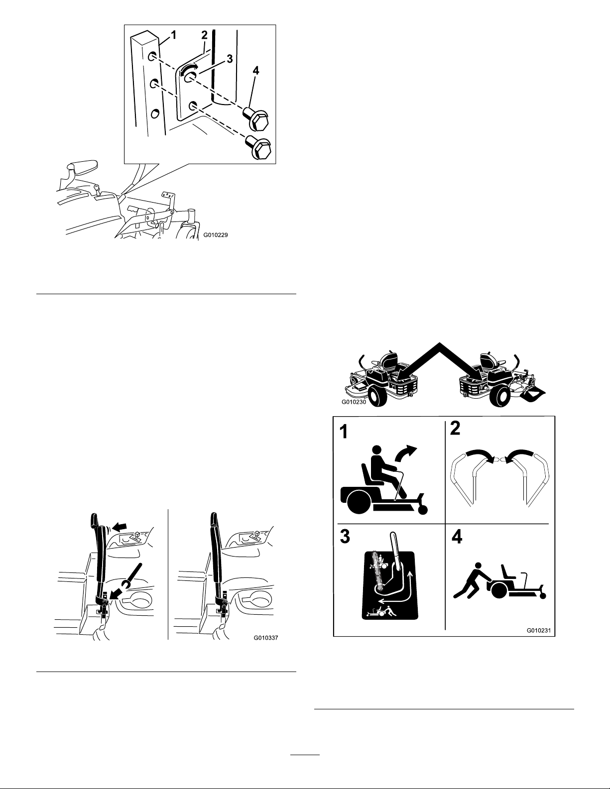
1.Removethe2boltsholdingthecontrollevertothe
controlarmshaft(Figure29).
2.Movethecontrollevertothenextsetofholes.
Securetheleverwiththe2bolts(
Figure29).
Note:Thecontrolleverscanalsobeinstalledon
theoutsideofthecontrolarmshafts.
23
Page 24
G010229
1
2
3
4
Figure29
G010337
G010230
2
3
4
1
1.Controlarmshaft3.Slotted,upperhole
2.Controllever
4.Bolt
3.Repeattheadjustmentfortheoppositecontrol
lever.
PushingtheMachinebyHand
Important:Alwayspushthemachinebyhand.
Nevertowthemachinebecausedamagemay
occur.
ToPushtheMachine
1.Parkthemachineonalevelsurfaceanddisengage
thebladecontrolswitch.
2.Movethemotioncontrolleversoutwardtoneutral
lockposition,stoptheengine,removethekey,and
waitforallmovingpartstostopbeforeleavingthe
operatingposition.Makesuretheparkingbrakeis
disengaged.
3.Locatethebypassleversattherearofthemachine,
ontheleftandrightsideoftheframe.
4.Movethebypassleversrearwardandthendown
tolocktheminplaceasshownin
disengagethewheelmotors.Repeatthisoneach
sideofthemachine.
Themachineisnowabletobepushedbyhand.
Figure31to
AdjustingtheTilt
Themotioncontrolleverscanbetiltedforeoraftfor
maximumoperatorcomfort.
1.Loosentheupperboltholdingthecontrolleverto
thecontrolarmshaft.
2.Loosenthelowerboltjustenoughtopivotthe
controlleverforeoraft(Figure29).Tightenboth
boltstosecurethecontrolinthenewposition.
3.Repeattheadjustmentfortheoppositecontrol
lever.
Figure30
1.Bypassleverdecal
2.Leverpositionfor
operatingthemachine
24
Figure31
3.Leverpositionforpushing
themachine
Page 25

ToOperatetheMachine
Cut1/3oftheGrassBlade
Movethebypasstothepositionforpushingthe
machine(
Figure31)toengagethewheelmotors.
UsingtheSideDischarge
Themowerhasahingedgrassdeectorthatdisperses
clippingstothesideanddowntowardtheturf.
DANGER
Withoutagrassdeector,dischargecover,or
completegrasscatcherassemblymountedin
place,youandothersareexposedtobladecontact
andthrowndebris.Contactwithrotatingmower
blade(s)andthrowndebriswillcauseinjuryor
death.
•Neverremovethegrassdeectorfromthe
mowerbecausethegrassdeectorroutes
materialdowntowardtheturf.Ifthe
grassdeectoriseverdamaged,replaceit
immediately.
•Neverputyourhandsorfeetunderthemower.
•Nevertrytoclearthedischargeareaormower
bladesunlessyoumovethebladecontrolswitch
(PTO)totheoffposition,rotatetheignition
keytooffandremovethekey .
•Makesurethegrassdeectorisinthedown
position.
Itisbesttocutonlyabout1/3ofthegrassblade.
Cuttingmorethanthatisnotrecommendedunless
grassissparse,oritislatefallwhengrassgrowsmore
slowly.
MowingDirection
Alternatemowingdirectiontokeepthegrassstanding
straight.Thisalsohelpsdisperseclippingswhich
enhancesdecompositionandfertilization.
MowatCorrectIntervals
Normally,moweveryfourdays.Butremember,
grassgrowsatdifferentratesatdifferenttimes.So
tomaintainthesamecuttingheight,whichisagood
practice,mowmoreofteninearlyspring.Asthegrass
growthrateslowsinmidsummer,mowlessfrequently.
Ifyoucannotmowforanextendedperiod,rstmow
atahighcuttingheight;thenmowagaintwodayslater
atalowerheightsetting.
CuttingSpeed
Toimprovecutquality,useaslowergroundspeedin
certainconditions.
AvoidCuttingTooLow
Ifthecuttingwidthofthemoweriswiderthanthe
moweryoupreviouslyused,raisethecuttingheightto
ensurethatuneventurfisnotcuttooshort.
OperatingTips
FastThrottleSetting
Forbestmowingandmaximumaircirculation,operate
theengineatthefastthrottleposition.Airisrequired
tothoroughlycutgrassclippings,sodonotsetthe
height-of-cutsolowastototallysurroundthemower
byuncutgrass.Alwaystrytohaveonesideofthe
mowerfreefromuncutgrass,whichallowsairtobe
drawnintothemower.
CuttingaLawnfortheFirstTime
Cutgrassslightlylongerthannormaltoensurethe
cuttingheightofthemowerdoesnotscalpanyuneven
ground.However,thecuttingheightusedinthepastis
generallythebestonetouse.Whencuttinggrasslonger
thansixinchestall,youmaywanttocutthelawntwice
toensureanacceptablequalityofcut.
LongGrass
Ifthegrassiseverallowedtogrowslightlylongerthan
normal,orifitcontainsahighdegreeofmoisture,raise
thecuttingheighthigherthanusualandcutthegrassat
thissetting.Thencutthegrassagainusingthelower,
normalsetting.
WhenStopping
Ifthemachine’sforwardmotionmustbestoppedwhile
mowing,aclumpofgrassclippingsmaydropontoyour
lawn.Toavoidthis,moveontoapreviouslycutarea
withthebladesengaged.
KeeptheUndersideoftheMower
Clean
Cleanclippingsanddirtfromtheundersideofthe
moweraftereachuse.Ifgrassanddirtbuildupinside
themower,cuttingqualitywilleventuallybecome
unsatisfactory.
25
Page 26

BladeMaintenance
Maintainasharpbladethroughoutthecuttingseason
becauseasharpbladecutscleanlywithouttearingor
shreddingthegrassblades.Tearingandshreddingturns
grassbrownattheedges,whichslowsgrowthand
increasesthechanceofdisease.Checkthecutterblades
dailyforsharpness,andforanywearordamage.File
downanynicksandsharpenthebladesasnecessary.If
abladeisdamagedorworn,replaceitimmediatelywith
agenuineTOROreplacementblade.
26
Page 27

Maintenance
RecommendedMaintenanceSchedule(s)
MaintenanceService
Interval
Aftertherst8hours
Aftertherst50hours
Beforeeachuseordaily
Every25hours
Every50hours
Every100hours
Every200hours
MaintenanceProcedure
•Changetheengineoil.
•Changethehydraulicsystemlterandoil.
•Checkthesafetyinterlocksystem.
•Checktheaircleanerfordirty,looseordamagedparts.
•Checktheengineoillevel.
•Checkairintakeandcoolingareas,cleanasnecessary.
•Checkthemowerblades.
•Inspectthegrassdeectorfordamage
•Cleanthemowerhousing.
•Greasealllubricationpoints.
•Servicethefoamelement.(moreoftenunderdusty ,dirtyconditions)
•Checktirepressure.
•Checkthehydraulicoillevelintheexpansiontank.
•Servicethepaperelement.(moreoftenunderdusty ,dirtyconditions)
•Inspectthebeltsforcracksandwear.
•Replacethepaperelement.(moreoftenunderdusty,dirtyconditions)
•Changetheengineoil.(moreoftenunderdusty,dirtyconditions)
•Cleantheblowerhousing(moreoftenunderdusty,dirtyconditions).
•Changetheengineoillter.
•Checksparkplug(s)conditionandgap.
Every400hours
Every500hours
Monthly
Yearlyorbeforestorage
•Changethehydraulicsystemlterandoil.
•Replacethesparkplug(s).
•Replacethefuellters(moreoftenunderdusty,dirtyconditions).
•Checkthebatterycharge.
•Paintchippedsurfaces.
•Checkallmaintenanceprocedureslistedabovebeforestorage.
Important:Refertoyourengineoperator’smanualforadditionalmaintenanceprocedures.
CAUTION
Ifyouleavethekeyintheignitionswitch,someonecouldaccidentlystarttheengineandseriouslyinjure
youorotherbystanders.
Removethekeyfromtheignitionbeforeyoudoanymaintenance.
27
Page 28
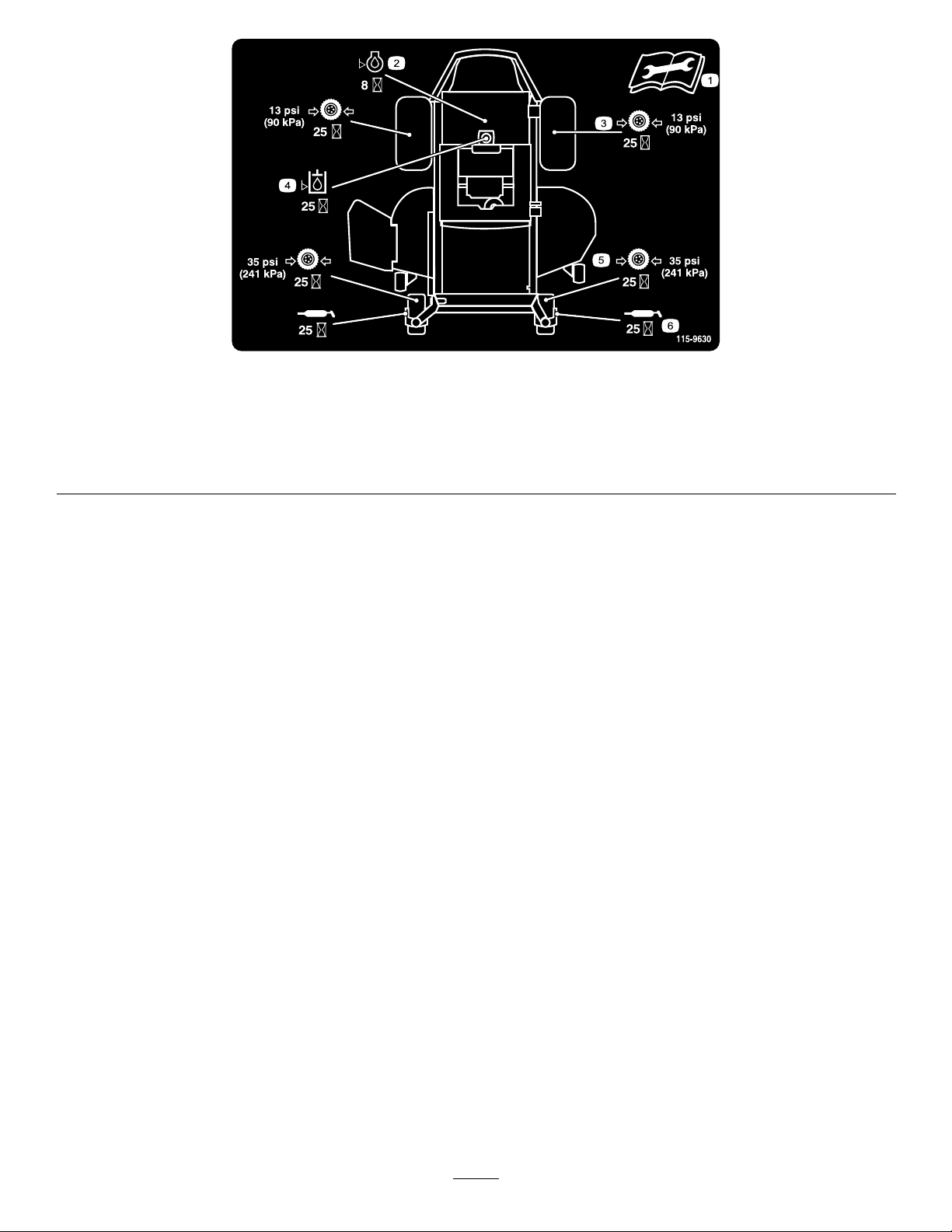
Figure32
Locatedontheseatpanunderside
1.ReadtheOperator’sManualbeforeperformingany
maintenance.
2.Checktheengineoilevery8hours5.Checkthecasterwheeltirepressureevery25hours
3.Checkthedrivewheeltirepressureevery25hours
4.Checkthehydraulicoilevery25hours
6.Lubricatethecasterwheelevery25hours
28
Page 29
Premaintenance
G009949
1
Lubrication
Procedures
GreasingtheBearings
RaisingtheSeat
Makesurethemotioncontrolleversarelockedinthe
neutrallockposition.Lifttheseatforward.
Thefollowingcomponentscanbeaccessedbyraising
theseat:
•Servicedecal
•Fuses
•Batteryandcables
ServiceInterval:Every25hours—Greaseall
lubricationpoints.
GreaseType:No.2GeneralPurposeLithiumBase
Grease
1.Parkthemachineonalevelsurfaceanddisengage
thebladecontrolswitch.
2.Movethemotioncontrolleversoutwardtothe
neutrallockposition,stoptheengine,removethe
key,andwaitforallmovingpartstostopbefore
leavingtheoperatingposition.
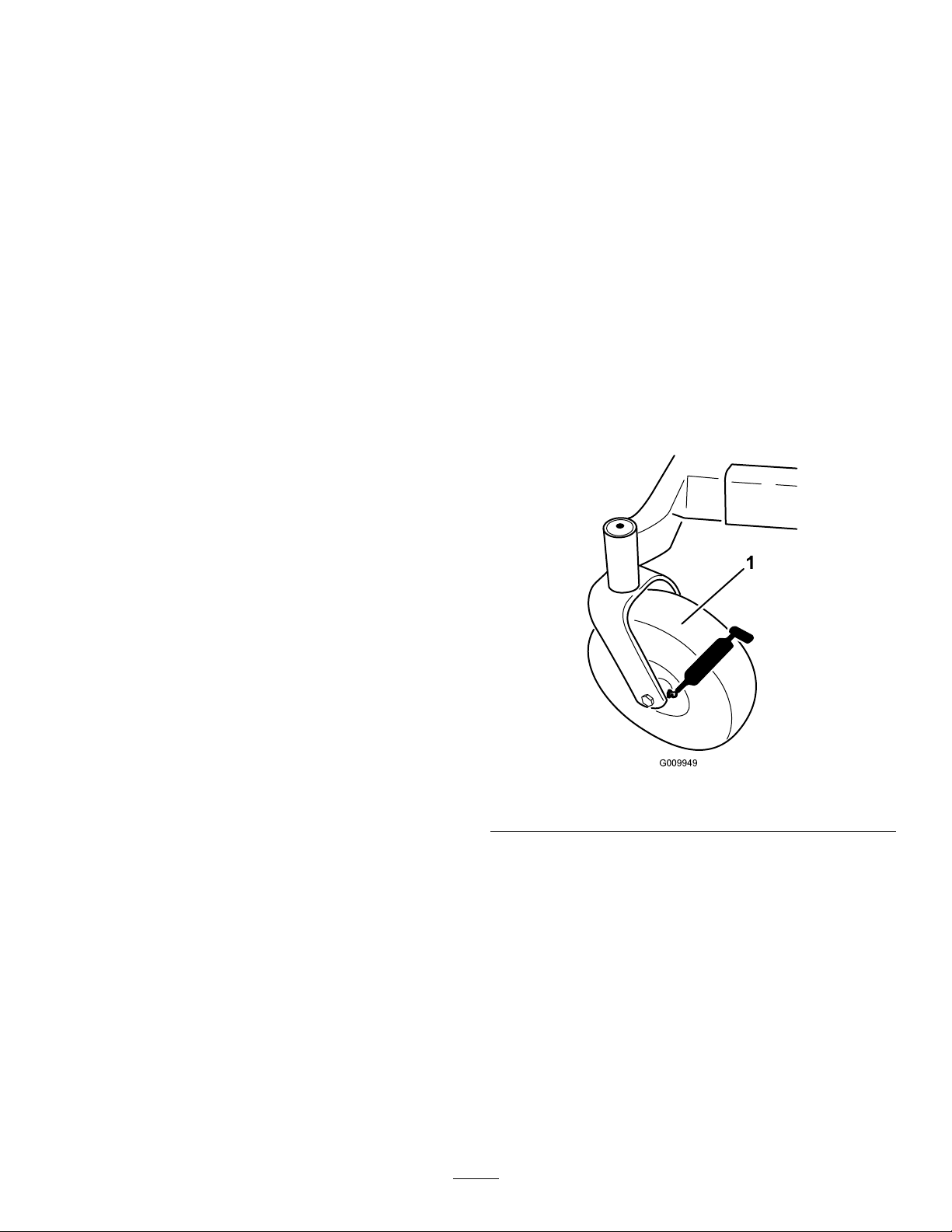
3.Cleanthegreasettings(
witharag.Makesuretoscrapeanypaintoffofthe
frontofthetting(s).
Figure33andFigure32)
Figure33
1.Frontcastertire
4.Connectagreaseguntoeachtting(Figure33and
Figure32).Pumpgreaseintothettingsuntilgrease
beginstooozeoutofthebearings.
5.Wipeupanyexcessgrease.
29
Page 30
EngineMaintenance
G010338
1
2
3
4
5
6
WARNING
Contactwithhotsurfacesmaycausepersonal
injury.
Keephands,feet,face,clothingandotherbody
partsawaythemuferandotherhotsurfaces.
ServicingtheAirCleaner
ServiceInterval:Beforeeachuseordaily—Checkthe
aircleanerfordirty,looseordamaged
parts.
Every25hours/Yearly(whichever
comesrst)—Servicethefoam
element.(moreoftenunderdusty,
dirtyconditions)
Figure34
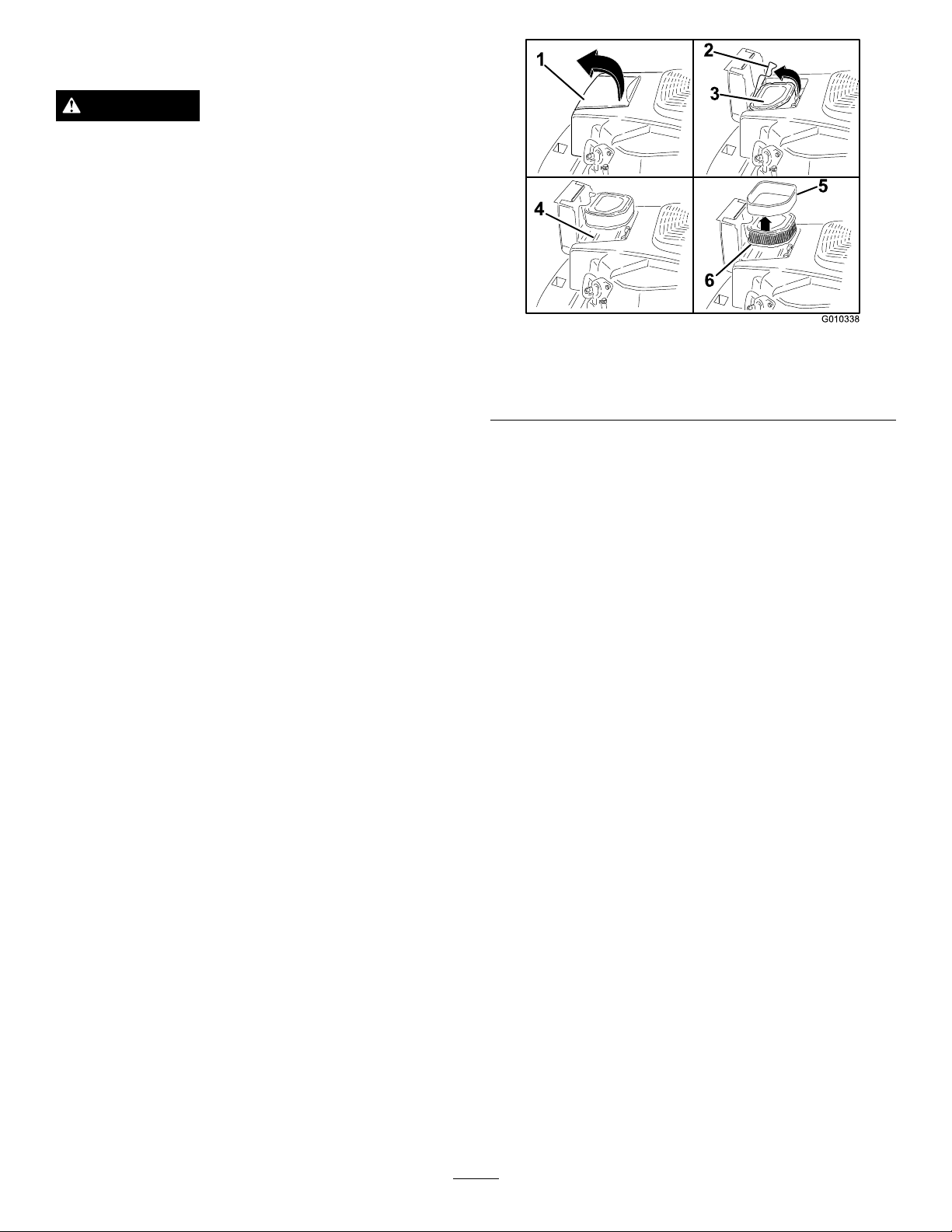
1.Aircleanercover4.Aircleanerbase
2.Aircleanerlatch5.Foamelement
3.Aircleaner6.Paperelement
Every50hours—Servicethepaper
element.(moreoftenunderdusty,
dirtyconditions)
Every100hours/Y early(whichever
comesrst)—Replacethepaper
element.(moreoftenunderdusty,
dirtyconditions)
Thisengineisequippedwithareplaceable,highdensity
paperaircleanerelement.Checktheaircleanerdailyor
beforestartingtheengine.Checkforabuildupofdirt
anddebrisaroundtheaircleanersystem.Keepthisarea
clean.Alsocheckforlooseordamagedcomponents.
Replaceallbentordamagedaircleanercomponents.
Note:Operatingtheenginewithlooseordamagedair
cleanercomponentscouldallowunlteredairintothe
enginecausingprematurewearandfailure.
Note:Servicetheaircleanermoreoftenunder
extremelydusty,dirtyconditions.
ServicingFoamElement
Checkthefoamelementevery25hoursofoperation
(moreoftenunderextremelydustyordirtyconditions).
Cleanorreplacetheelementasnecessary.
Replacetheaircleanerelementyearly ,orevery100
hours.
1.Opentheaircleanercoverdoorontheblower
housingtoaccesstheaircleanerelement(
2.Unhookthelatchandremovetheaircleaner
(Figure34).
3.Washthefoamelementinwarmwaterwith
detergent.Rinsetheelementthoroughlyuntilall
tracesofdetergentareeliminated.Squeezeout
excesswater(donotwring)andallowthefoam
elementtoairdry.
4.Saturatethefoamelementwithnewengineoil.
Squeezeoutallexcessoil.
5.Reinstallthefoamelementoverthepaperaircleaner
element.
Figure34).
6.Cleantheaircleanerbaseasrequiredandcheck
condition.
7.Installtheaircleanerontotheaircleanerbase.
Securewiththelatch.
8.Closetheaircleanercoverdoor.
ServicingPaperElement
Checkthepaperelementevery50hoursofoperation
(moreoftenunderextremelydustyordirtyconditions).
Cleanorreplacetheelementasnecessary.
30
Page 31
Replacetheaircleanerelementyearly ,orevery100
hours.
1.Opentheaircleanercoverdoorontheblower
housingtoaccesstheaircleanerelement(
2.Unhookthelatchandremovetheair
cleaner(Figure34).
3.Removethefoamelementandinspect.Cleanand
replaceasnecessary.
4.Gentlytapthepaperelementtodislodgedirt.Do
notwashthepaperelementorusepressurized
air,asthiswilldamagetheelement.Replaceadirty,
bent,ordamagedelement.Handlethenewelement
carefully;donotuseifthesealingsurfacesarebent
ordamaged.
5.Cleantheaircleanerbaseasrequiredandcheck
condition.
6.Installthepaperelementontotheaircleanerbase.
Securewiththelatch.
7.Closetheaircleanercoverdoor.
Figure34).
CheckingtheEngineOilLevel
ServiceInterval:Beforeeachuseordaily
Note:Checktheoilwhentheengineiscold.
WARNING
Contactwithhotsurfacesmaycausepersonal
injury.
Keephands,feet,face,clothingandotherbody
partsawaythemuferandotherhotsurfaces.
Important:Donotoverllthecrankcasewithoil
becausedamagetotheenginemayresult.Donot
runenginewithoilbelowthelowmarkbecausethe
enginemaybedamaged.
1.Disengagethebladecontrolswitch(PTO),movethe
motioncontrolleverstotheneutrallockedposition
andsettheparkingbrake.
2.Makesuretheengineisstopped,level,andiscoolso
theoilhashadtimetodrainintothesump.
ServicingtheEngineOil
OilType:Detergentoil(APIserviceSG,SH,SJ,or
higher)
CrankcaseCapacity:1.6-1.8qt(1.7-1.9l)whenthe
lterischanged
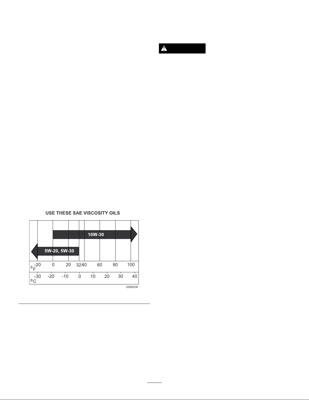
Viscosity:Seethetablebelow .
Figure35
Important:UseotherthanserviceclassSG,SH,SJ,
orhigheroilorextendingoilchangeintervalslonger
thanrecommendedcancauseenginedamage.
Note:Syntheticoilsmeetingthelistedclassications
maybeusedwithoilchangesperformedatthe
recommendedintervals.Howevertoallowpistonrings
toproperlyseat,aneworrebuiltengineshouldbe
operatedforatleast50hoursusingstandardpetroleum
basedoilbeforeswitchingtosyntheticoil.
3.Tokeepdirt,grassclippings,etc.,outoftheengine,
cleantheareaaroundtheoilllcap/dipstickbefore
removingit.
4.Removethedipstickandwipetheoiloff.
Note:Checkthestyleofoildipstickfortheengine.
Dipstickswiththreadedcapsareuseddifferently
whencheckingtheoillevelthandipsticksthatare
seatedbypushingthemintoplace.
5.Reinsertthedipstickintothetubetochecktheoil
level:
•Threadeddipstickcaps:restthecaponthe
tube.Turnitcouterclockwiseuntiltheoildipstick
dropsdowntothelowestpointofthethread
leads.Donotscrewthecapontothetube.
•Unthreadeddipstickcaps:reinsertthedipstick
andpushrmlyintoplace.
6.Removethedipstickoutandchecktheoillevel.
Theoillevelshouldbeupto,butnotover,the
“FULL”or“F”markonthedipstick
7.Ifthelevelislow ,addoilofthepropertype,uptothe
“FULL”or“F”markonthedipstick.Alwayscheck
thelevelwiththedipstickbeforeaddingmoreoil.
Note:Topreventextensiveenginewearordamage,
alwaysmaintaintheproperoillevelinthecrankcase.
Neveroperatetheenginewiththeoillevelbelowthe
“ADD”or“L”markorabovethe“FULL”or“F”
markonthedipstick.
8.Removedipstickandcheckoillevel.Thelevelshould
bebetweenthe“FullorF”and“ AddorL”marks.If
31
Page 32
low,addoilofthepropertypeuptothefullmark.
G009950
G010457
1 2
3
4
5
6
Reinstalloilllcap/dipstickandscrewtight.
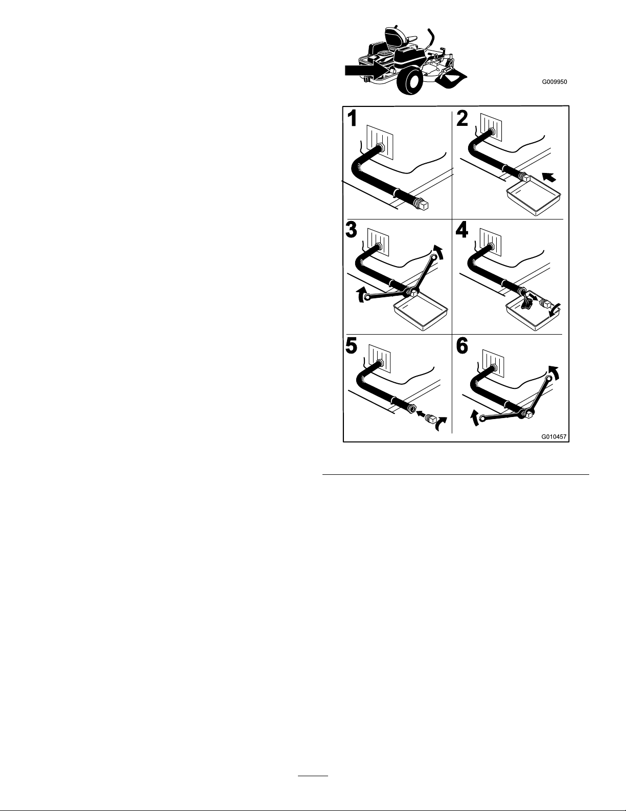
ChangingtheEngineOil
ServiceInterval:Aftertherst8hours
Every100hours(moreoftenunder
dusty,dirtyconditions)
Note:Disposeoftheusedoilatarecyclingcenter.
1.Starttheengineandletitrunveminutes.This
warmstheoilsoitdrainsbetter.
2.Parkthemachinesothatthedrainsideisslightly
lowerthantheoppositesidetoassuretheoildrains
completely.
3.Disengagethebladecontrolswitch(PTO),movethe
motioncontrolleverstotheneutrallockposition
andsettheparkingbrake.
4.Stoptheengine,removethekey ,andwaitforall
movingpartstostopbeforeleavingtheoperating
position(
Figure36).
Figure36
32
Page 33
5.Slowlypourapproximately80%ofthespeciedoil
G009950
G008748
3/4
1
2
3
4
5
6
G010230
intothellertubeandslowlyaddtheadditionaloil
tobringittotheFullmark.
6.Installtheoilllcap/dipstick.
7.Checktheoillevel;refertoCheckingtheOilLevel.
8.Slowlyaddadditionaloiltobringittothefullmark.
9.Installtheoilllcap/dipstick.
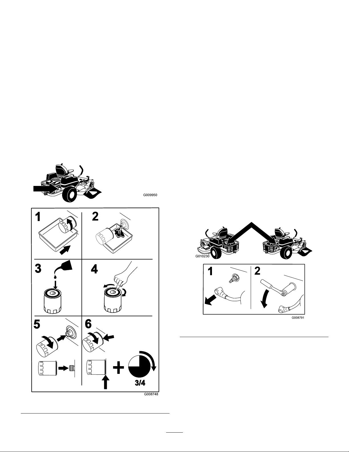
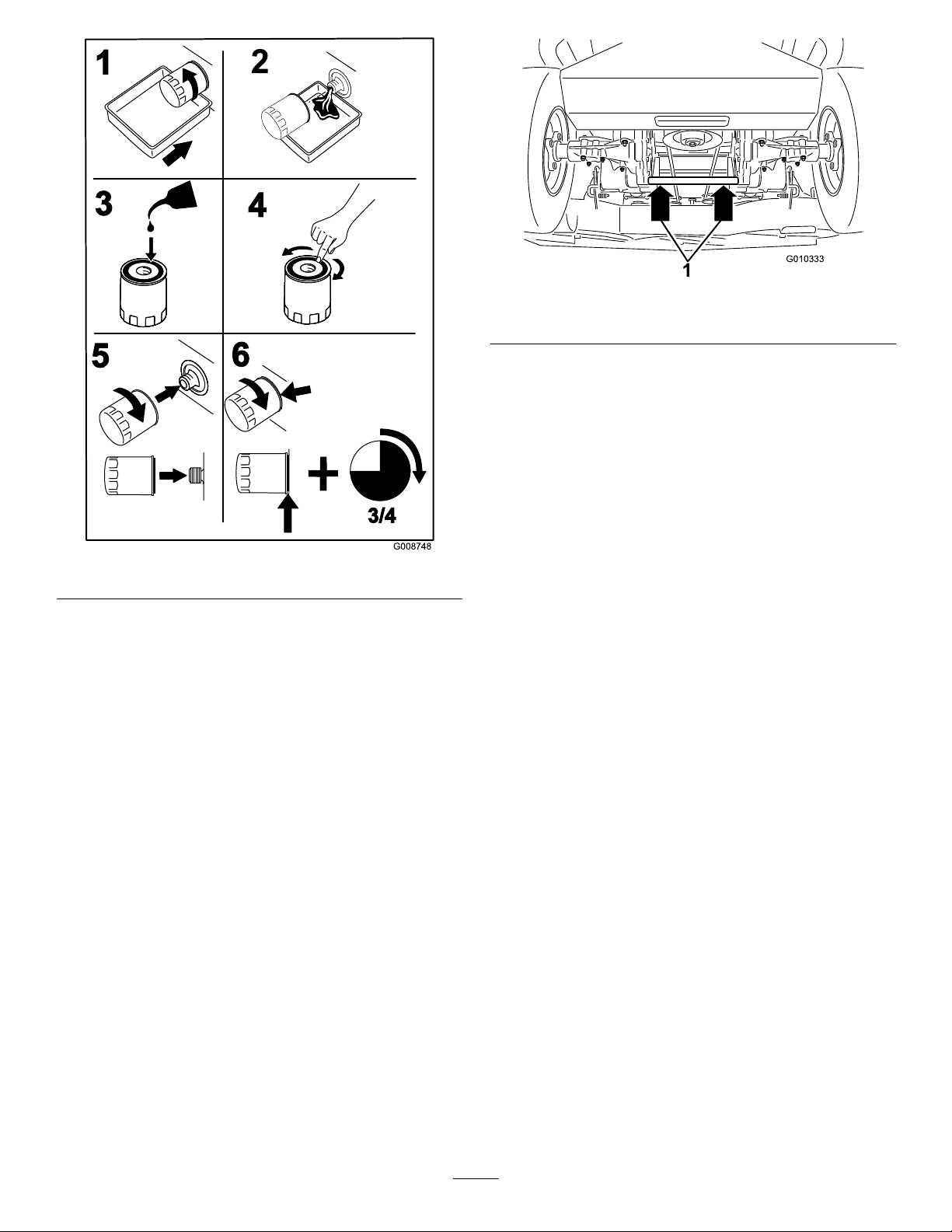
Note:Ensuretheoilltergaskettouchestheengine
andthenanextra3/4turniscompleted.
3.Fillthecrankcasewiththepropertypeofnewoil;
refertoChangingtheOil.
ServicingtheSparkPlug
ServiceInterval:Every200hours—Checkspark
plug(s)conditionandgap.
ChangingtheEngineOilFilter
ServiceInterval:Every200hours
Note:Changetheengineoilltermorefrequently
whenoperatingconditionsareextremelydustyorsandy.
1.Draintheoilfromtheengine;refertoChangingthe
EngineOil.
2.Changetheengineoillter(
Figure37).
Every500hours—Replacethespark
plug(s).
ThesparkplugisRFIcompliant.Equivalentalternate
brandplugscanalsobeused.Sparkplugreplacementis
recommendedat500hours.
Type:ChampionXC12YC(orequivalent)
AirGap:0.030inch(0.76mm)
RemovingtheSparkPlug
1.Disengagethebladecontrolswitch(PTO),movethe
motioncontrolleverstotheneutrallockposition
andsettheparkingbrake.
2.Stoptheengine,removethekey ,andwaitforall
movingpartstostopbeforeleavingtheoperating
position.
Figure37
Figure38
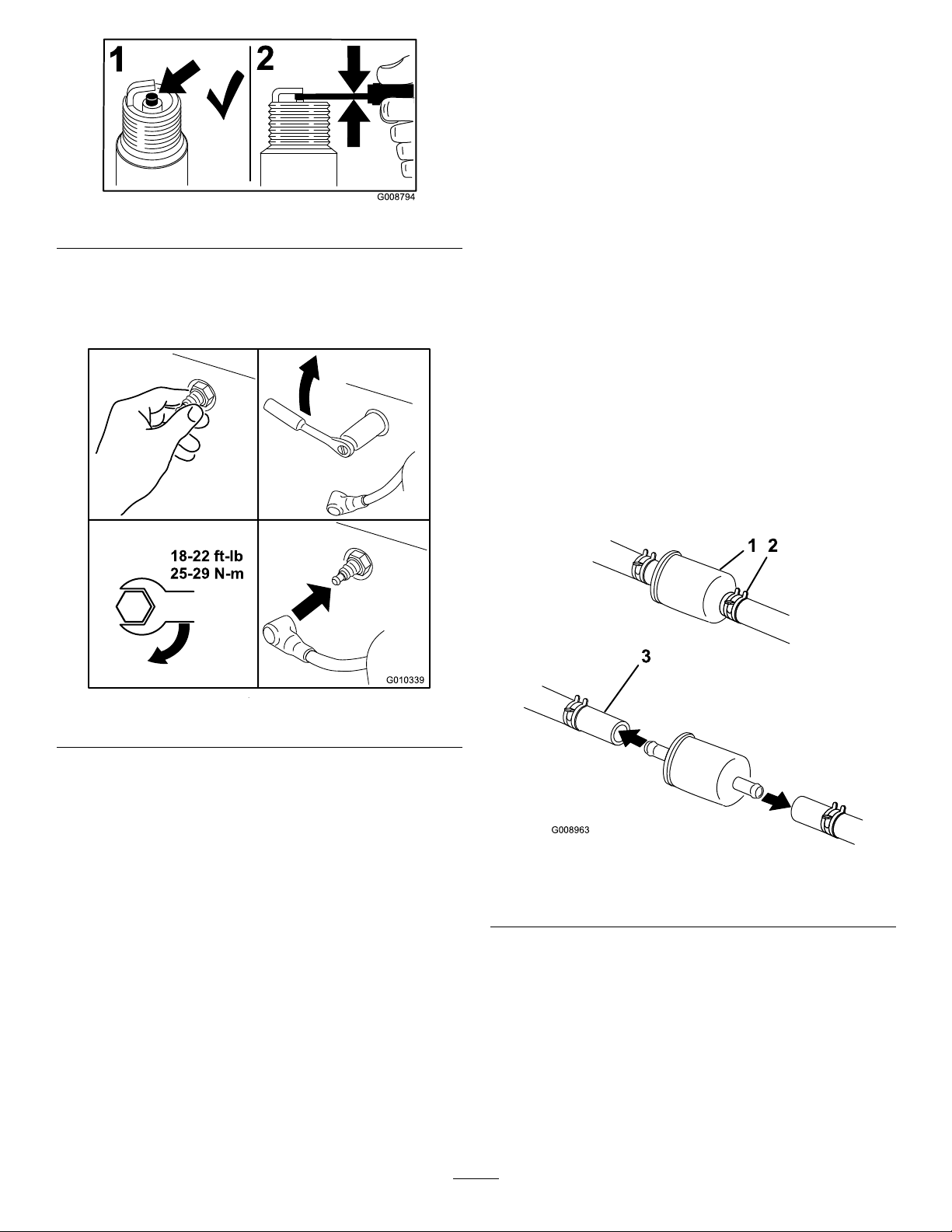
CheckingtheSparkPlug
Important:Nevercleanthesparkplug(s).Always
replacethesparkplug(s)whenithas:ablack
coating,wornelectrodes,anoilylm,orcracks.
Ifyouseelightbrownorgrayontheinsulator,the
engineisoperatingproperly.Ablackcoatingonthe
insulatorusuallymeanstheaircleanerisdirty.
Setthegapto0.030inches(0.76mm).
33
Page 34
G008794
1
2
InstallingtheSparkPlug
18-22ft-lb
25-29N-m
G010339
G008963
12
3
Figure39
FuelSystem
Maintenance
ReplacingtheFuelFilter
ServiceInterval:Every500hours/Yearly(whichever
comesrst)(moreoftenunderdusty,
dirtyconditions).
1.Disengagethebladecontrolswitch(PTO),movethe
motioncontrolleverstotheneutrallockposition,
andsettheparkingbrake.
Tightenthesparkplugto18-22ft-lb(25-29N-m).
Figure40
2.Stoptheengine,removethekey ,andwaitforall
movingpartstostopbeforeleavingtheoperating
position.
3.Allowthemachinetocooldown.
4.Stoptheengine,removethekey ,andwaitforall
movingpartstostopbeforeleavingtheoperating
position.
5.Squeezetheendsofthehoseclampstogetherand
slidethemawayfromthelter(
Figure41).
CleaningtheBlowerHousing
Toensurepropercooling,makesurethegrassscreen,
coolingns,andotherexternalsurfacesoftheengine
arekeptcleanatalltimes.
Annuallyorevery100hoursofoperation(moreoften
underextremelydusty ,dirtyconditions),removethe
blowerhousingandanyothercoolingshrouds.Clean
thecoolingnsandexternalsurfacesasnecessary.Make
surethecoolingshroudsarereinstalled.Torquethe
blowerhousingscrewsto5.5ft-lb(7.5N-m).
Important:Operatingtheenginewithablocked
grassscreen,dirtyorpluggedcoolingns,and/or
coolingshroudsremoved,willcauseenginedamage
duetooverheating.
Figure41
1.Fuellter
2.Hoseclamp
6.Removethelterfromthefuellines.
7.Installanewlterandmovethehoseclampsclose
tothelter(Figure41).
8.Openthefuelshutoffvalve.
Note:Itisimportanttoreinstallthefuellinehosesand
securewithplastictiesthesameastheywereoriginally
installedatthefactorytokeepthefuellineawayfrom
componentsthatcouldcausefuellinedamage.
34
3.Fuelline
Page 35
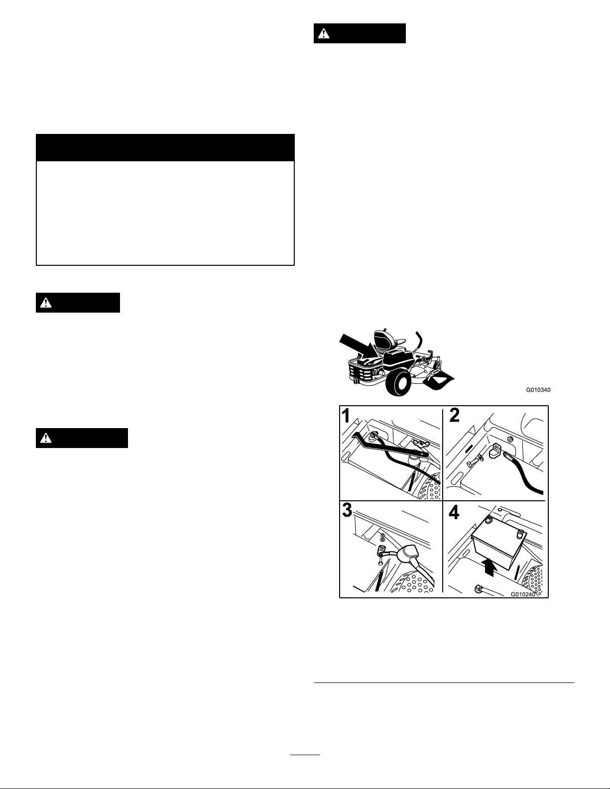
ElectricalSystem
G010340
G010240
1
2
3
4
Maintenance
ServicingtheBattery
ServiceInterval:Monthly
WARNING
CALIFORNIA
Proposition65Warning
WARNING
Incorrectbatterycableroutingcoulddamagethe
machineandcablescausingsparks.Sparkscan
causethebatterygassestoexplode,resultingin
personalinjury.
•AlwaysDisconnectthenegative(black)battery
cablebeforedisconnectingthepositive(red)
cable.
•AlwaysReconnectthepositive(red)battery
cablebeforereconnectingthenegative(black)
cable.
Batteryposts,terminals,andrelated
accessoriescontainleadandleadcompounds,
chemicalsknowntotheStateofCalifornia
tocausecancerandreproductiveharm.
Washhandsafterhandling.
DANGER
Batteryelectrolytecontainssulfuricacidwhichisa
deadlypoisonandcausessevereburns.
Donotdrinkelectrolyteandavoidcontactwith
skin,eyesorclothing.Wearsafetyglassestoshield
youreyesandrubberglovestoprotectyourhands.
RemovingtheBattery
WARNING
Batteryterminalsormetaltoolscouldshortagainst
metalmachinecomponentscausingsparks.Sparks
cancausethebatterygassestoexplode,resulting
inpersonalinjury.
1.Disengagethebladecontrolswitch(PTO),movethe
motioncontrolleverstotheneutrallockposition
andsettheparkingbrake.
2.Stoptheengine,removethekey ,andwaitforall
movingpartstostopbeforeleavingtheoperating
position.
3.Removethewingnutsecuringthebatteryclamp
Figure42).
(
•Whenremovingorinstallingthebattery ,donot
allowthebatteryterminalstotouchanymetal
partsofthemachine.
•Donotallowmetaltoolstoshortbetween
thebatteryterminalsandmetalpartsofthe
machine.
Figure42
1.Removethewingnutand
clamp
2.Removethenegative
batterycablebeforethe
positive
4.Firstdisconnectthenegativebatterycable(black)
fromthenegative(-)(black)batteryterminal
(Figure42).
35
3.Removethepositive
batterycable
4.Removebattery
Page 36
5.Slidetheredterminalbootoffthepositive(red)
batteryterminalandremovethepositive(+)(red)
batterycable(Figure42).
6.Removetheclamp(
Figure42).
7.Removethebattery.
InstallingtheBattery
1.Positionbatteryinthetraywiththeterminalposts
oppositefromthehydraulictank(Figure42).
2.First,installthepositive(red)batterycableto
positive(+)batteryterminal.
3.Theninstallthenegativebatterycableandground
wiretothenegative(-)batteryterminal.
4.Securethecableswith2bolts,2washers,and
2locknuts(
Figure42).
5.Slidetheredterminalbootontothepositive(red)
batterypost.
6.Installtheclampandsecureitwiththewingnut
Figure42).
(
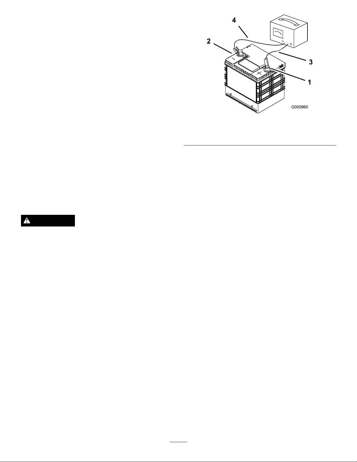
ChargingtheBattery
Figure43
1.PositiveBatteryPost
2.NegativeBatteryPost
3.Red(+)ChargerLead
4.Black(-)ChargerLead
ServicingtheFuses
Theelectricalsystemisprotectedbyfuses.Itrequires
nomaintenance,however,ifafuseblowscheckthe
component/circuitforamalfunctionorshort.
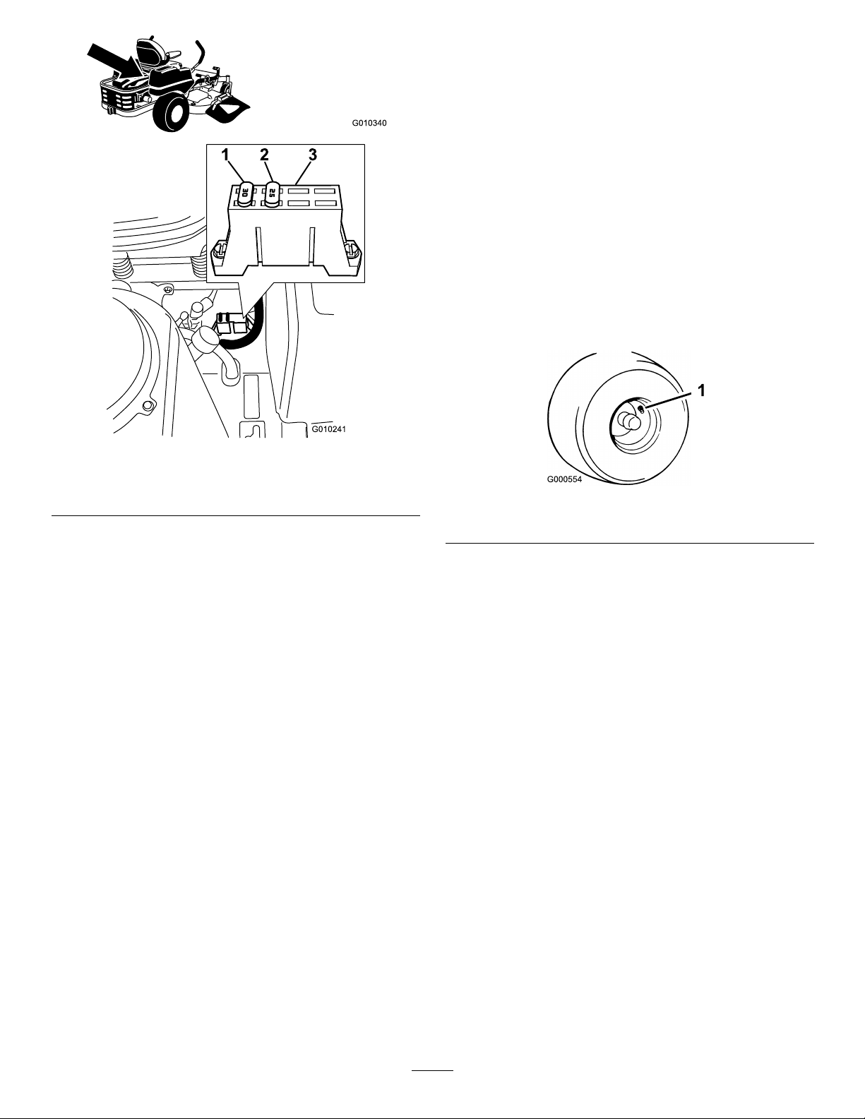
Fuses:
WARNING
Chargingthebatteryproducesgassesthatcan
explode.
Neversmokenearthebatteryandkeepsparksand
amesawayfrombattery.
Important:Alwayskeepthebatteryfullycharged.
Thisisespeciallyimportanttopreventbattery
damagewhenthetemperatureisbelow32°F(0°C).
1.Chargebatteryfor10to15minutesat25to30amps
or30minutesat10amps.
2.Whenthebatteryisfullycharged,unplugthecharger
fromtheelectricaloutlet,thendisconnectthe
chargerleadsfromthebatteryposts(
3.Installthebatteryinthemachineandconnectthe
batterycables,refertoInstallingtheBattery.
Note:Donotrunthemachinewiththebattery
disconnected,electricaldamagemayoccur.
Figure43).
•Main,30amp,blade-type
•Engine,20amp,blade-type
1.Thefusesarelocatedonrighthandconsolenextto
theseat(
Figure44).
2.Toreplacethefuses,pulloutonthefusetoremove
it.
3.Installanewfuse(Figure44).
36
Page 37
G010340
30
25
1 2
3
G010241
Figure44
1.30amp3.Fuseblock
2.25amp
DriveSystem
Maintenance
CheckingtheTirePressure
ServiceInterval:Every25hours—Checktirepressure.
Maintaintheairpressureinthefrontandreartiresas
specied.Uneventirepressurecancauseunevencut.
Checkthepressureatthevalvestem(Figure45).Check
thetireswhentheyarecoldtogetthemostaccurate
pressurereading.
RearTires:13psi(90kPa)
FrontTires(casterwheels):35psi(241kPa)
Figure45
1.Valvestem
37
Page 38
HydraulicSystem
G010253
1
2
3
G010254
1
2
3
4
5
Maintenance
OilType:20w-50engineoil.
Important:Useoilspeciedorequivalent.Other
uidscouldcausesystemdamage.
CheckingtheHydraulicOil
Level
ServiceInterval:Every25hours
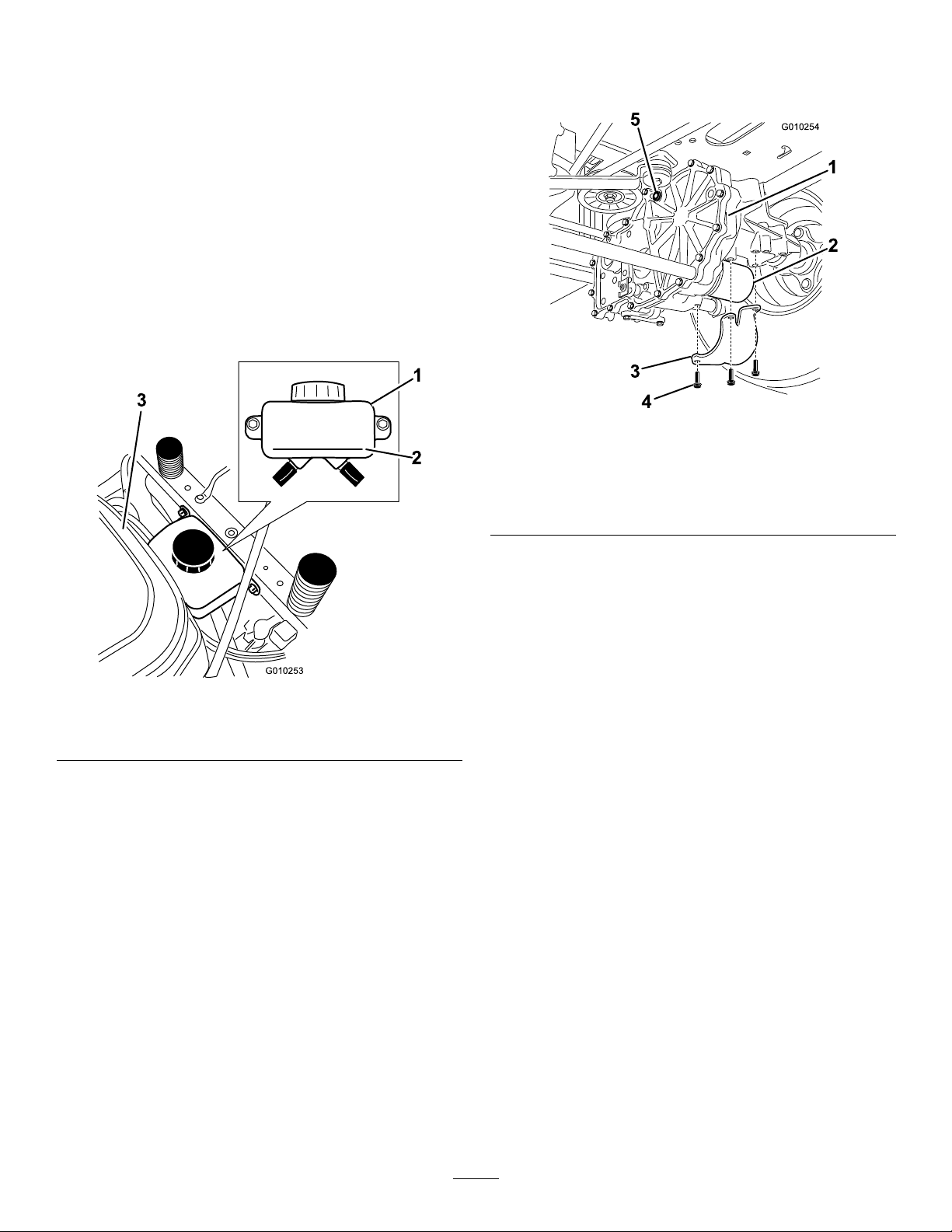
Checkexpansionreservoirandifnecessaryadd20W-50
engineoiltotheFULLCOLDline
2.Locatethelterandguardsoneachtransaxledrive
system(Figure47).Removethreescrewssecuring
thelterguardandguard.
Figure47
Rightsideshown
Figure46
1.Expansionreservoir3.Engine
2.FullColdline
ChangingtheHydraulic
SystemFilterandOil
Thelterandoilarechangedatthesametime.DoNot
reuseoil.Oncethenewlterisinstalledandoilisadded
anyairinthesystemmustbepurged.
Thebleedingprocessisrepeateduntiltheoilremains
attheFULLCOLDlineinthereservoirafterpurging.
Failuretoproperlyperformthisprocedurecan
resultinirreparabledamagetothetransaxledrive
system.
1.Transaxledrive
2.Oillter
3.Filterguard
3.Carefullycleanareaaroundlters.Itisimportant
thatnodirtorcontaminationenterhydraulicsystem.
4.Locateandremovetheventplugoneach
transmission
5.Placeacontainerbelowtheltertocatchtheoilthat
drainswhenthelterisremoved.Unscrewthelter
toremoveandallowoiltodrainfromdrivesystem.
Repeatthisprocedureforbothlters.
4.Screws
5.Ventplug
InstallingtheHydraulicSystemFilters
ServiceInterval:Aftertherst50hours
Every400hours
RemovingHydraulicSystemFilters
1.Stopengine,waitforallmovingpartstostop,and
allowenginetocool.Removethekeyandengage
theparkingbrake.
38
Page 39
G008748
3/4
1
2
3
4
5
6
G010333
1
Figure49
1.Jackingpoints
2.Startengineandmovethrottlecontrolaheadto1/2
throttleposition.Disengageparkingbrake.
A.Movethebypassleversintothepushingthe
machineposition;refertothePushingthe
MachinebyHandsectioninOperation.With
thebypassvalvesopenandtheenginerunning,
slowlymovethemotioncontrolleversinboth
forwardandreverse(5or6times).
Figure48
1.Applyathincoatofoilonthesurfaceoftherubber
sealofeachlter.
2.Turnthelterclockwiseuntilrubbersealcontacts
thelteradapterthentightenthelteranadditional
3/4to1fullturn.Repeatfortheotherlter
3.Installthelterguardsovereachlteraspreviously
removed.Usethethreescrewstosecurethelter
guards.
4.Slowlypourthespeciedoilthroughexpansion
reservoiruntiloilcomesoutofventplugholes.Stop
andinstalltheventplugs.Torqueplugsto180in-lb
(20.3N-m).
5.ContinuetoaddoiluntilitreachestheFULLCOLD
lineontheexpansionreservoir.Proceedtothe
BleedingtheHydraulicSystemsection.
Important:Failuretoperformthe
the Hy draulic System
hydraulicltersandoilcanresultinirreparable
damagetothetransaxledrivesystem.
procedureafterchanging
BleedingtheHydraulicSystem
B.Movethebypassleversintotheoperating
themachineposition.Withthebypassvalve
closedandtheenginerunning,slowlymovethe
directionalcontrolinbothforwardandreverse
directions(5to6times).
C.Stoptheengineandchecktheoillevelinthe
expansionreservoir.Addthespeciedoilas
untilitreachestheFULLCOLDlineonthe
expansionreservoir.
3.Repeatstep2untilalltheairiscompletelypurged
fromthesystem.
Whenthetransaxleoperatesatnormalnoiselevels
andmovessmoothlyforwardandreverseatnormal
speeds,thenthetransaxleisconsideredpurged.
4.Checktheoillevelintheexpansionreservoirone
lasttime.Addthespeciedoilasuntilitreaches
theFULLCOLDlineontheexpansionreservoir
ifnecessary.
Bleeding
1.Raisetherearofmachineupandsupportwithjack
stands(orequivalentsupport)justhighenoughto
allowdrivewheelstoturnfreely.
39
Page 40
MowerDeck
G009679
1
2
3
Maintenance
ServicingtheCuttingBlades
Maintainsharpbladesthroughoutthecuttingseason
becausesharpbladescutcleanlywithouttearingor
shreddingthegrassblades.Tearingandshreddingturns
grassbrownattheedges,whichslowsgrowthand
increasesthechanceofdisease.
Checkthecutterbladesdailyforsharpness,andforany
wearordamage.Filedownanynicksandsharpenthe
bladesasnecessary.Ifabladeisdamagedorworn,
replaceitimmediatelywithagenuineTororeplacement
blade.Forconvenientsharpeningandreplacement,you
maywanttokeepextrabladesonhand.
WARNING
Figure50
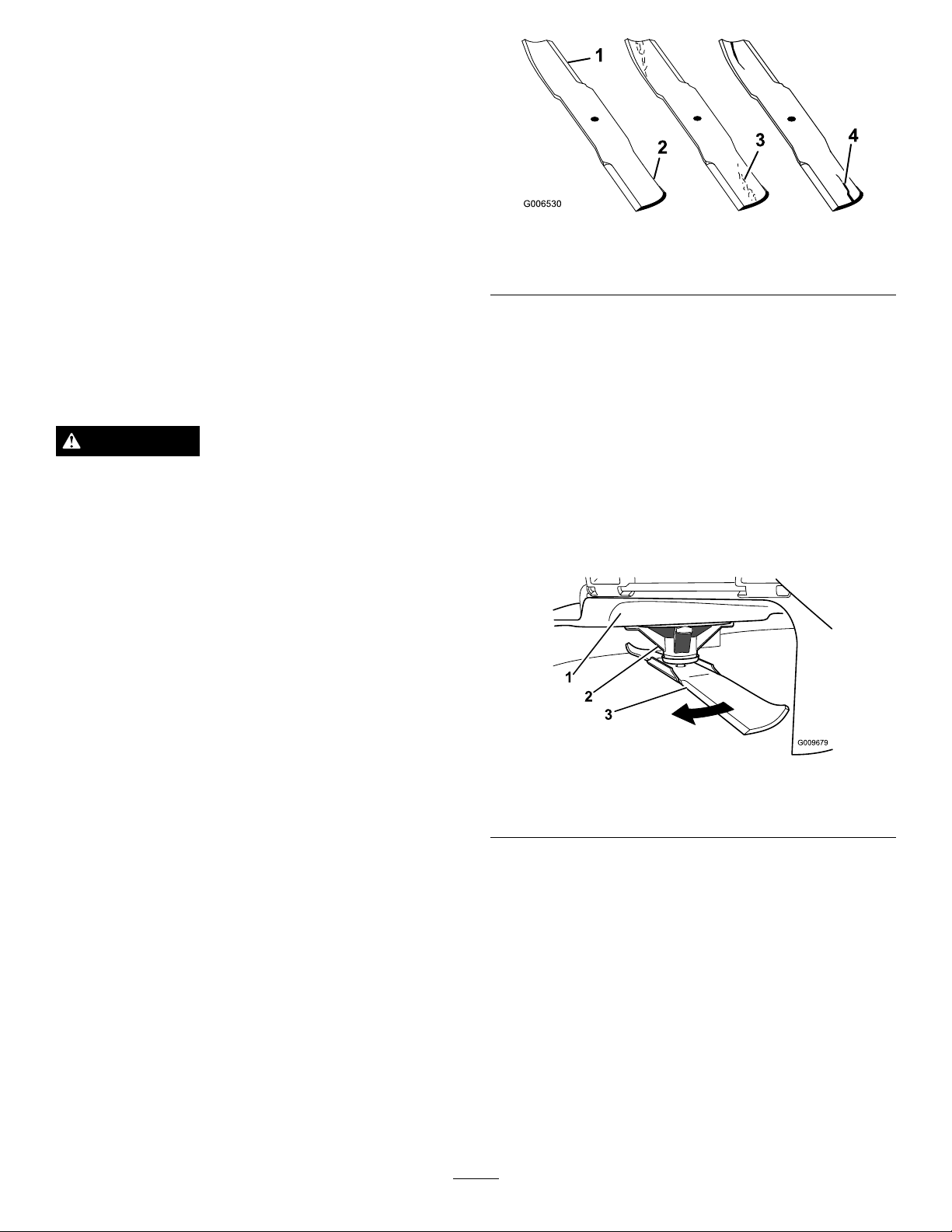
1.CuttingEdge3.Wear/slotForming
2.CurvedArea4.Crack
CheckingforBentBlades
Note:Themachinemustbeonalevelsurfaceforthe
followingprocedure.
1.Raisethemowerdecktothehighestheight-of-cut
position;alsoconsideredthe’transport’position.
Awornordamagedbladecanbreak,andapiece
ofthebladecouldbethrownintotheoperator’s
orbystander’sarea,resultinginseriouspersonal
injuryordeath.
•Inspectthebladeperiodicallyforwearor
damage.
•Replaceawornordamagedblade.
BeforeInspectingorServicingthe
Blades
Parkthemachineonalevelsurface,disengagetheblade
controlswitch(PTO),andsettheparkingbrake.Turn
theignitionkeytoOff.Removethekey.
InspectingtheBlades
ServiceInterval:Beforeeachuseordaily
1.Inspectthecuttingedges(Figure50).Iftheedges
arenotsharporhavenicks,removeandsharpenthe
blades.RefertoSharpeningtheBlades.
2.Whilewearingthicklypaddedglovesorother
adequatehandprotectionslowlyrotatebladeto
bemeasuredintoapositionthatallowseffective
measurementofthedistancebetweenthecutting
edgeandthelevelsurfacethemachineison.
Figure51
1.Deck3.Blade
2.Spindlehousing
2.Inspecttheblades,especiallythecurvedarea
(Figure50).Ifyounoticeanydamage,wear,oraslot
forminginthisarea(Figure50),immediatelyinstalla
newblade.
40
Page 41
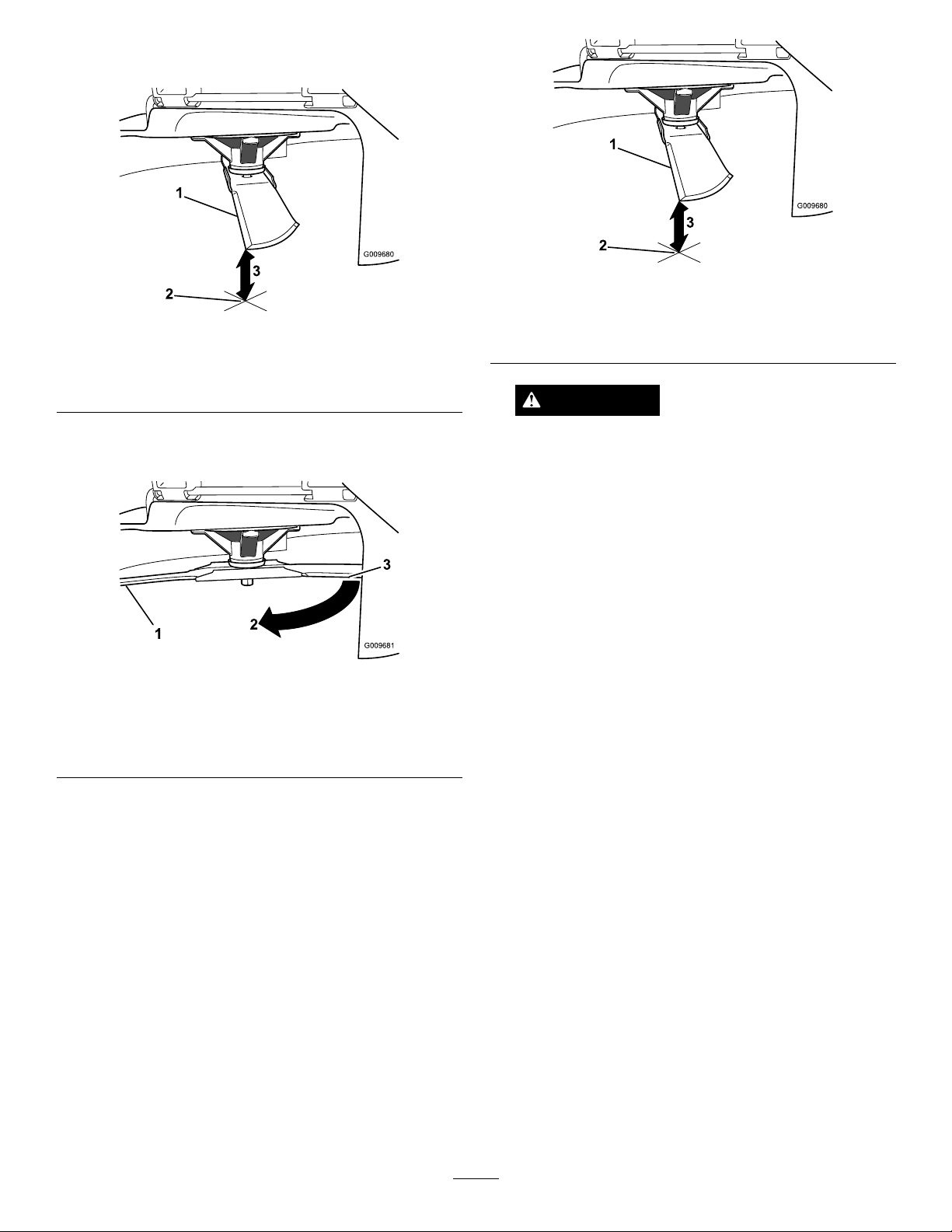
3.Measurefromthetipofthebladetotheatsurface
G009680
1
2
3
G009681
1
2
3
G009680
1
2
3
here.
Figure52
1.Blade,inpositionformeasuring
2.Levelsurface
3.Measureddistancebetweenbladeandsurface(A)
Figure54
1.Opposingbladeedge,inpositionformeasuring
2.Levelsurface
3.Secondmeasureddistancebetweenbladeandsurface(B)
WARNING
4.Rotatethesameblade180degreessothatthe
opposingcuttingedgeisnowinthesameposition.
Figure53
1.Blade,sidepreviouslymeasured
2.Measurementpositionusedpreviously
3.Opposingsideofbladebeingmovedintomeasurement
position
5.Measurefromthetipofthebladetotheatsurface
here.Thevarianceshouldbenomorethan1/8inch
(3mm).
Abladethatisbentordamagedcouldbreak
apartandcouldseriouslyinjureorkillyouor
bystanders.
•Alwaysreplacebentordamagedbladewith
anewblade.
•Neverleorcreatesharpnotchesinthe
edgesorsurfacesofblade.
A.IfthedifferencebetweenAandBisgreater
than1/8inch(3mm)replacethebladewitha
newblade.RefertoRemovingtheBladesand
InstallingtheBlades.
Note:Ifabentbladeisreplacedwithanewone
andthedimensionobtainedcontinuestoexceed
1/8inch(3mm),thebladespindlecouldbebent.
ContactanAuthorizedToroDealerforservice.
B.Ifthevarianceiswithinconstraints,movetothe
nextblade..
Repeatthisprocedureoneachblade.
RemovingtheBlades
Bladesmustbereplacedifasolidobjectishit,ifthe
bladeisoutofbalanceorisbent.Toensureoptimum
performanceandcontinuedsafetyconformanceof
themachine,usegenuineT ororeplacementblades.
Replacementbladesmadebyothermanufacturersmay
resultinnon-conformancewithsafetystandards.
Holdthebladeendusingaragorthickly-paddedglove.
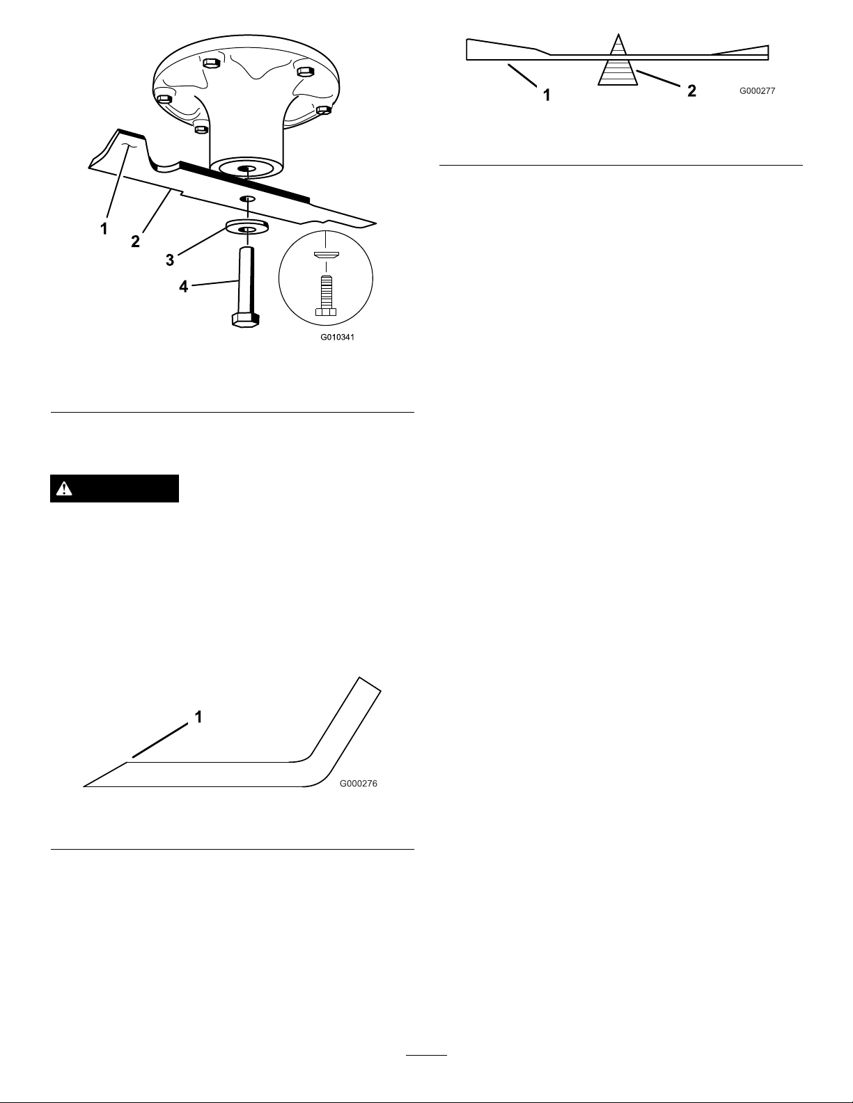
Removethebladebolt,curvedwasher,andbladefrom
thespindleshaft(Figure55).
41
Page 42
1
2
3
4
G010341
Figure55
1.SailAreaofBlade3.Curvedwasher
2.Blade4.BladeBolt
Figure57
1.Blade2.Balancer
InstallingtheBlades
1.Installthebladeontothespindleshaft(Figure55).
Important:Thecurvedpartoftheblademust
bepointingupwardtowardtheinsideofthe
mowertoensurepropercutting.
2.Installthespringdiskandbladebolt.Thespring
diskconemustbeinstalledtowardthebolthead
Figure55).Torquethebladeboltto100-110ft-lb
(
(135-150N-m).
MowerDeckLeveling
SharpeningtheBlades
WARNING
Whensharpeningblade,piecesofbladecouldbe
thrownandcauseseriousinjury.
Wearpropereyeprotectionwhensharpeningblade.
1.Usealetosharpenthecuttingedgeatbothends
oftheblade(Figure56).Maintaintheoriginalangle.
Thebladeretainsitsbalanceifthesameamountof
materialisremovedfrombothcuttingedges.
Figure56
1.Sharpenatoriginalangle
Checktoensurethemowerdeckislevelanytimeyou
installthemowerorwhenyouseeanunevencuton
yourlawn.
Themowerdeckmustbecheckedforbentblades
priortoleveling;anybentbladesmustberemoved
andreplaced.RefertotheCheckingforBentBlades
procedurebeforecontinuing.
Themowerdeckmustbeleveledside-to-siderstthen
thefronttorearslopecanbeadjusted.
Requirements:
•Themachinemustbeonalevelsurface.
•Allfourtiremustbeproperlyinated.Referto
CheckingtheTirePressureintheDriveSystem
Maintenancesection.
CheckingSide-to-SideLevel
Themowerbladesmustbelevelfromsidetoside.
Checktheside-to-sidelevelanytimeyouinstallthe
mowerorwhenyouseeanunevencutonyourlawn.
2.Checkthebalanceofthebladebyputtingitona
bladebalancer(Figure57).Ifthebladestaysina
horizontalposition,thebladeisbalancedandcanbe
used.Ifthebladeisnotbalanced,lesomemetaloff
theendofthesailareaonly(Figure55).Repeatthis
procedureuntilthebladeisbalanced.
1.Parkthemachineonalevelsurfaceanddisengage
thebladecontrolswitch.
2.Movethemotioncontrolleversoutwardtothe
neutrallockposition,stoptheengine,removethe
key,andwaitforallmovingpartstostopbefore
leavingtheoperatingposition.
3.Carefullyrotatethebladessidetoside.
4.Measurebetweentheoutsidecuttingedgesand
theatsurface(Figure58).Ifbothmeasurements
42
Page 43
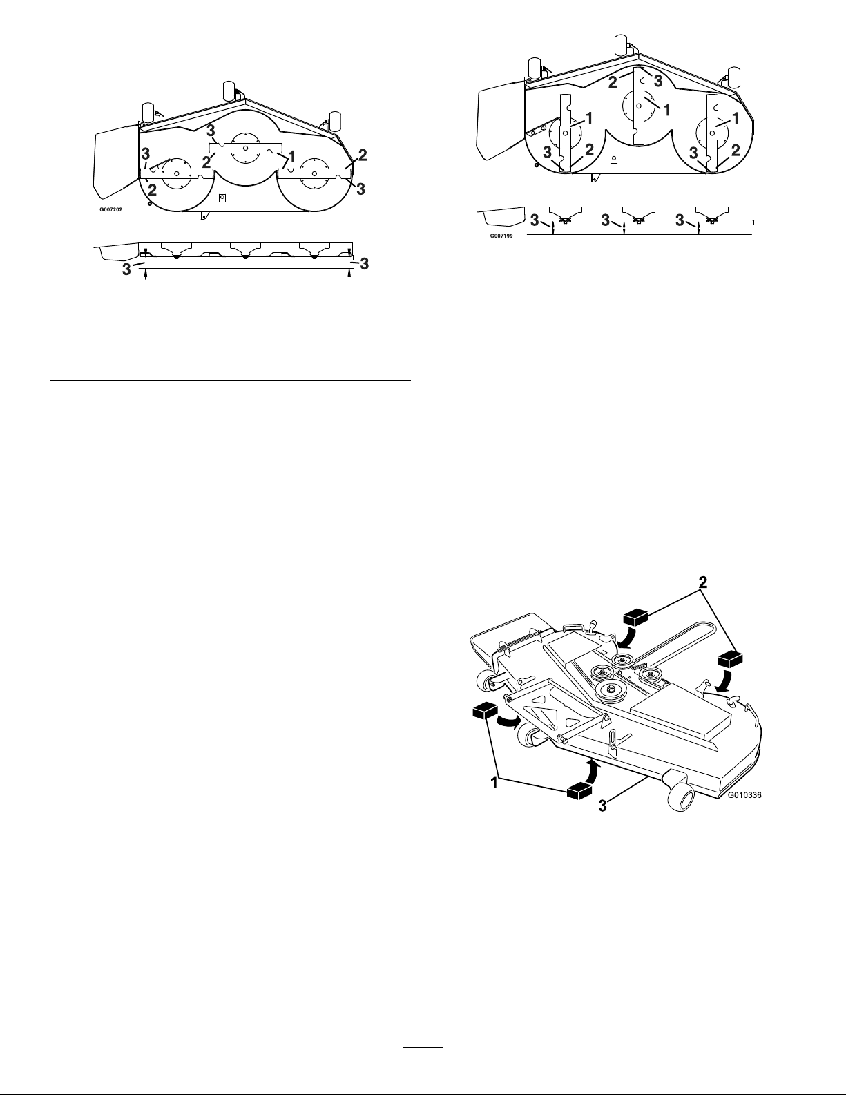
arenotwithin3/16inch(5mm),anadjustmentis
G010336
1
2
3
required;continuetotheLevelingprocedure.
Figure58
1.Bladessidetoside
2.Outsidecuttingedges
3.Measurefromthetipofthe
bladetotheatsurface
here
CheckingtheFront-to-RearBlade
Slope
Checkthefront-to-rearbladelevelanytimeyouinstall
themower.Ifthefrontofthemowerismorethan
5/16inch(7.9mm)lowerthantherearofthemower,
adjustthebladelevelusingthefollowinginstructions:
1.Parkthemachineonalevelsurfaceanddisengage
thebladecontrolswitch.
Figure59
1.Bladesfronttorear3.Measurefromthetipofthe
bladetotheatsurface
here
2.Outsidecuttingedges
LevelingtheMowerDeck
1.Setanti-scalprollerstotopholesorremove
completelyforthisprocedure.
2.Settheheight-of-cutlevertothe3inch(76mm)
position.
3.Placetwo2-5/8inch(6.66cm)blocksundereach
sideofthefrontedgeofthedeck,butnotunderthe
anti-scalprollerbrackets.Placetwo2-7/8inch(7.30
cm)thickblocksundertherearedgeofthecutting
deckskirt;oneoneachsideofthecuttingdeck.
2.Movethemotioncontrolleversoutwardtothe
neutralposition,engagetheparkingbrake,stopthe
engine,removethekey ,andwaitforallmovingparts
tostopbeforeleavingtheoperatingposition.
3.Carefullyrotatethebladessotheyarefacingfront
torear(
Figure59).
4.Measurefromthetipofthefrontbladetotheat
surfaceandthetipoftherearbladetotheatsurface
Figure59).Ifthefrontbladetipisnot1/16-5/16
(
inch(1.6-7.9mm)lowerthantherearbladetip,
continuetotheLevelingtheMowerDeckprocedure.
Figure60
1.Woodblock,2-5/8inch
(6.66cm)thick
2.Woodblock,2-7/8inch
(7.30cm)thick
3.Frontedge
4.Loosenthelevelingadjustlockingnuts(item3)on
allfourcornerssothatthedeckissittingsecurely
onallfourblocks.Makesurethatthedeckhangers
areallthewaydown(atthetopoftheslot)andthe
deckliftfootleverispushedbackagainstthestop,
43
Page 44
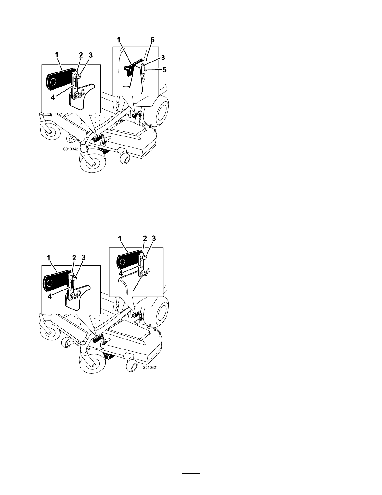
thentightenthefourlevelingadjustlockingnuts
G010342
1
2
3
4
1
6
5
3
G010321
1
2
3
1
2
3
4
4
(Figure61).
5.Recheckthatblockstjustsnuglyunderthedeck
skirt.Makesureallattachmentboltsaretight
6.Verifythedeckislevelbycheckingtheside-to-side
levelandfront-to-rearbladeslope;repeatdeck
levelingprocedureifnecessary.
InspectingtheBelts
ServiceInterval:Every50hours
Checkthebeltsforsquealingwhenthebeltisrotating,
bladesslippingwhencuttinggrass,frayedbeltedges,
burnmarksandcracksaresignsofawornmowerbelt.
Replacethemowerbeltifanyoftheseconditionsare
evident.
ReplacingtheMowerBelt
Figure61
54inchMowerDecks
1.Deckliftarm4.Slotindeckhanger
2.Deckhanger
3.Levelingadjustlockingnut6.Reardeckhangerbracket
5.Slotinreardeckhanger
bracket
Squealingwhenthebeltisrotating,bladesslippingwhen
cuttinggrass,frayedbeltedges,burnmarksandcracks
aresignsofawornmowerbelt.ContactanAuthorized
ServiceDealertoreplacethemowerbeltifanyofthese
conditionsareevident.
RemovingtheMower
Parkthemachineonalevelsurfaceanddisengagethe
bladecontrolswitch.Movethemotioncontrollevers
outwardtotheneutralposition,engageparkingbrake,
stoptheengine,removethekey,andwaitforallmoving
partstostopbeforeleavingtheoperatingposition.
Lowerthemowertothe3inch(76mm)height-of-cut
position.Removethemowerbeltfromtheengine
pulley;refertotheReplacingtheMowerBeltprocedure.
Lowerthemowertothelowestheight-of-cut.Selectone
ofthefollowingproceduresdependingonthemower
decksizeinstalledtocompletetheremoval.
1.MovethespringloadedJ-hooksoutoftheslotin
therearhangerbracketsonbothsidesofthedeck
Figure63).
(
1.Deckliftarm
2.Deckhanger
Figure62
60inchMowerDecks
3.Levelingadjustlockingnut
4.Slotindeckhanger
44
Page 45
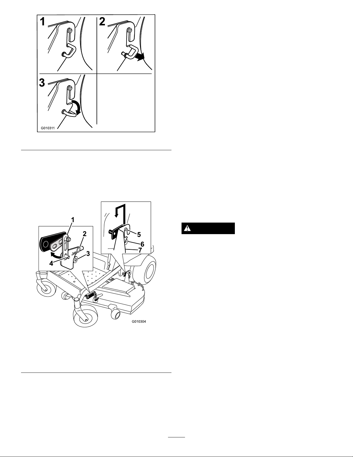
G01031 1
2
3
1
Figure63
G010304
1
2
3
4
5
6
7
2.Removethehardwarefromthefrontdeckhangers
onbothsidesofthedeck(Figure64).
3.Carefullyliftthedeckofftherearhangerboltsand
lowerthefrontofthemowerdecktotheground
Figure64).
(
InstallingtheMower
1.Parkthemachineonalevelsurfaceanddisengage
thebladecontrolswitch.
2.Movethemotioncontrolleversoutwardtothe
neutrallockposition,stoptheengine,removethe
key,andwaitforallmovingpartstostopbefore
leavingtheoperatingposition.
3.Slidethemowerunderthemachine.
4.Lowertheheight-of-cutlevertothelowestposition.
Placetheheight-of-cutpininthelockpositionfor
lowestheight-of-cut.
5.Lifttherearofthemowerdeckandguidethehanger
bracketsovertherearhangerbolts(
6.Attachthefrontsupportonthemowerdecktothe
frontdeckhangersandsecurethemwithawasher
andhairpincotter(
7.Installthemowerbeltontotheenginepulley;refer
toReplacingtheMowerBelt.
Figure64).
Figure64).
ReplacingtheGrassDeector
Figure64
1.Deckhanger5.Rearhangerbolts
2.Hairpincotter6.J-hook
3.Washer7.Reardeckhangerbracket
4.Weldedpostondeck
4.Raisetheheight-of-cuttothetransportposition
ServiceInterval:Beforeeachuseordaily—Inspectthe
grassdeectorfordamage
WARNING
Anuncovereddischargeopeningcouldallowthe
lawnmowertothrowobjectsintheoperator’sor
bystander’sdirectionandresultinseriousinjury.
Also,contactwiththebladecouldoccur.
Neveroperatethelawnmowerunlessyouinstalla
mulchplate,dischargedeector,orgrasscollection
system.
Inspectthegrassdeectorfordamagebeforeeachuse.
Replaceanydamagedpartsbeforeuse.
1.Disengagethespringfromthenotchinthedeector
bracketandslidetherodoutoftheweldeddeck
brackets,spring,anddischargedeector(Figure65).
Removethedamagedorworndischargedeector.
5.Slidethemoweroutfromunderneaththemachine.
Note:Retainallpartsforfutureinstallation.
45
Page 46
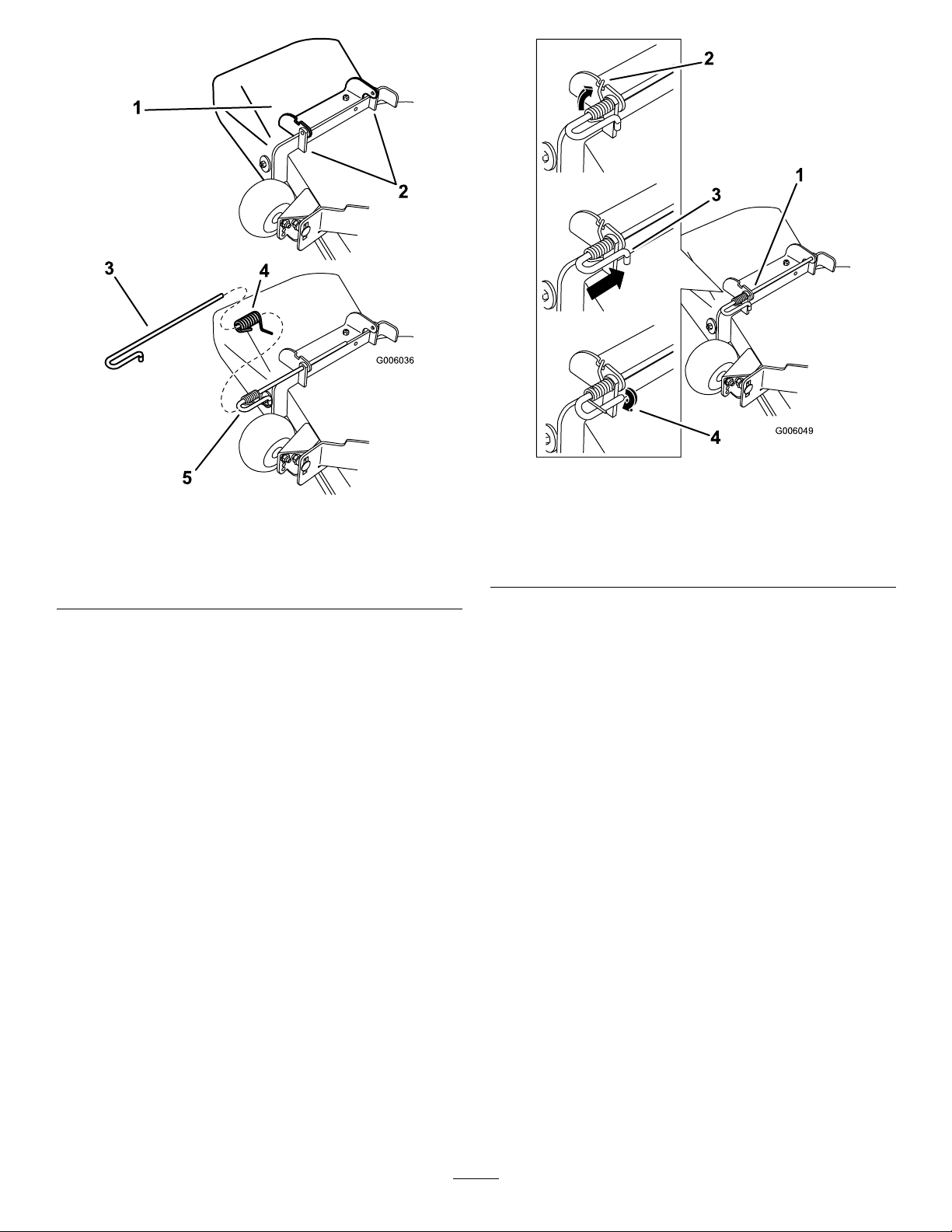
G006036
1
2
3
4
5
Figure65
G006049
1
2
3
4
1.Deectorassembly4.Spring
2.Deckbrackets
3.Rod
5.Springinstalledoverthe
rod
2.Positionthenewdischargedeectorassemblywith
thebracketendsbetweentheweldedbracketsonthe
deckasshowninFigure65.
3.Installthespringontothestraightendoftherod.
Positionthespringontherodasshowninsothe
shorterspringendiscomingfromundertherod
beforethebendandgoingovertherodasitreturns
fromthebend.
4.Liftthelongendofthespringandplaceitintothe
notchonthedeectorassemblybracket(
Figure66).
Figure66
1.Rodandspringassembly
partiallyinstalled
2.Longendofthespring
installedintothenotchin
thedeectorbracket
3.Rod,shortend,moved
behindmowerbracket
4.Shortend,retainedby
mowerbracket.
5.Securetherodandspringassemblybytwistingitso
theshortendoftherodcanbeplacedbehindthe
frontbracketweldedtothedeck(
Figure66).
Important:Thegrassdeectormustbespring
loadedinthedownposition.Liftthedeector
uptotestthatitsnapstothefulldownposition.
46
Page 47
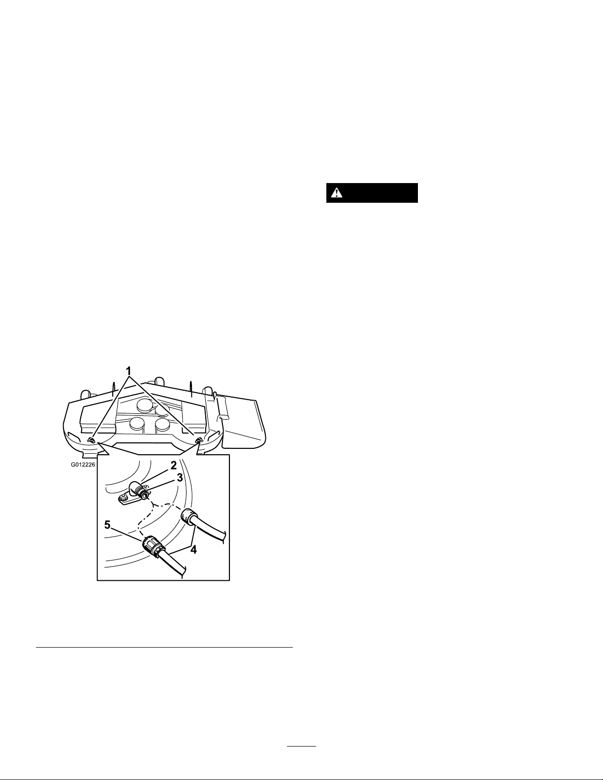
Cleaning
G012226
1
2
3
4
5
WashingtheUndersideofthe
Mower
6.Disengagethebladecontrolswitch,stoptheengine,
andremovetheignitionkey .Waitforallmoving
partstostop.
7.Turnthewateroffandremovethecouplingfrom
thewashouttting.
ServiceInterval:Beforeeachuseordaily—Cleanthe
mowerhousing.
Washtheundersideofthemoweraftereachuseto
preventgrassbuildupforimprovedmulchactionand
clippingdispersal.
1.Parkthemachineonalevelsurfaceanddisengage
thebladecontrolswitch.
2.Movethemotioncontrolleversoutwardtothe
neutrallockposition,stoptheengine,removethe
key,andwaitforallmovingpartstostopbefore
leavingtheoperatingposition.
3.Attachthehosecouplingtotheendofthemower
washouttting,andturnthewateronhigh
Figure67).
(
Note:Spreadpetroleumjellyonthewashouttting
O-ringtomakethecouplingslideoneasierand
protecttheO-ring.
Note:Ifthemowerisnotcleanafteronewashing,
soakitandletitstandfor30minutes.Thenrepeat
theprocess.
8.Runthemoweragainforonetothreeminutesto
removeexcesswater.
WARNING
Abrokenormissingwashoutttingcould
exposeyouandotherstothrownobjectsorblade
contact.Contactwithbladeorthrowndebris
cancauseinjuryordeath.
•Replacebrokenormissingwashouttting
immediately,beforeusingmoweragain.
•Neverputyourhandsorfeetunderthe
mowerorthroughopeningsinthemower.
WasteDisposal
Engineoil,batteries,hydraulicoil,andenginecoolant
arepollutantstotheenvironment.Disposeofthese
accordingtoyourstateandlocalregulations.
Figure67
1.Washoutttinglocations
2.Washouttting5.Coupling
3.O-ring
4.Lowerthemowertothelowestheight-of-cut.
5.Sitontheseatandstarttheengine.Engagetheblade
controlswitchandletthemowerrunforoneto
threeminutes.
4.Hose
47
Page 48

Storage
B.Runtheenginetodistributeconditionedfuel
throughthefuelsystem(5minutes).
CleaningandStorage
1.Disengagethebladecontrolswitch(PTO),setthe
parkingbrake,andturntheignitionkeytoOff.
Removethekey.
2.Removegrassclippings,dirt,andgrimefromthe
externalpartsoftheentiremachine,especiallythe
engineandhydraulicsystem.Cleandirtandchaff
fromtheoutsideoftheenginecylinderheadnsand
blowerhousing.
Important:Youcanwashthemachinewith
milddetergentandwater.Donotpressure
washthemachine.Avoidexcessiveuseof
water,especiallynearthecontrolpanel,engine,
hydraulicpumps,andmotors.
3.Checkthebrake;refertoServicingtheBrakeinthe
MaintenanceSection.
4.Servicetheaircleaner;refertoServicingtheAir
CleanerintheMaintenanceSection.
5.Greasethemachine;refertoGreasingand
LubricationintheMaintenanceSection.
C.Stoptheengine,allowittocool,anddrainthe
fueltank;refertoServicingtheFuelTankinthe
MaintenanceSection.
D.Restarttheengineandrunituntilitstops.
E.Disposeoffuelproperly.Recycleasperlocal
codes.
Important:Donotstore
stabilizer/conditionedfuelover90days.
13.Checkandtightenallbolts,nuts,andscrews.Repair
orreplaceanypartthatisdamaged.
14.Paintallscratchedorbaremetalsurfaces.Paintis
availablefromyourAuthorizedServiceDealer.
15.Storethemachineinaclean,drygarageorstorage
area.Removethekeyfromtheignitionswitchand
keepitoutofreachofchildrenorotherunauthorized
users.Coverthemachinetoprotectitandkeepit
clean.
6.Changethecrankcaseoil;refertoServicingthe
EngineOilintheMaintenanceSection.
7.Checkthetirepressure;refertoCheckingtheTire
PressureintheMaintenanceSection.
8.Changethehydrauliclter;refertoServicingthe
HydraulicSystemintheMaintenanceSection.
9.Chargethebattery;refertoServicingtheBatteryin
theMaintenanceSection.
10.Scrapeanyheavybuildupofgrassanddirtfromthe
undersideofthemower,thenwashthemowerwith
agardenhose.
Note:Runthemachinewiththebladecontrol
switch(PTO)engagedandtheengineathighidle
for2to5minutesafterwashing.
11.Checktheconditionoftheblades;refertoServicing
theCuttingBladesintheMaintenanceSection.
12.Preparethemachineforstoragewhennon-use
occursover30days.Preparethemachineforstorage
asfollows:
A.Addapetroleumbasedstabilizer/conditioner
tofuelinthetank.Followmixinginstructions
fromthestabilizermanufacturer.Donotusean
alcoholbasedstabilizer(ethanolormethanol).
Note:Afuelstabilizer/conditionerismost
effectivewhenmixedwithfreshfuelandused
atalltimes.
48
Page 49

Troubleshooting
Problem
Starterdoesnotcrank
Enginewillnotstart,startshard,orfails
tokeeprunning
PossibleCauseCorrectiveAction
1.Bladecontrolswitch(PTO)isengaged.1.Movebladecontrolswitch(PTO)to
2.Parkingbrakeisnoton.
3.Driveleversarenotinneutrallock
position.
4.Operatorisnotseated.4.Sitontheseat.
5.Batteryisdead.
6.Electricalconnectionsarecorrodedor
loose.
7.Fuseisblown.
8.Relayorswitchisdefective.8.ContactanAuthorizedServiceDealer.
1.Fueltankisempty.
2.Fuelshutoffvalveisclosed.2.Openthefuelshutoffvalve.
3.Oillevelinthecrankcaseislow.
4.Thethrottleandchokearenotinthe
correctposition.
5.Dirtinfuellter.5.Replacethefuellter.
6.Dirt,water,orstalefuelisinthefuel
system.
7.Aircleanerisdirty.
8.Seatswitchisnotfunctioningproperly.8.Checktheseatswitchindicator.
9.Electricalconnectionsarecorroded,
looseorfaulty.
10.Relayorswitchisdefective.10.ContactanAuthorizedServiceDealer.
11.Faultysparkplug.
12.Sparkplugwireisnotconnected.12.Checkthesparkplugwireconnection.
disengaged.
2.Settheparkingbrake.
3.Ensurethedriveleversareinthe
neutrallockposition.
5.Chargethebattery .
6.Checktheelectricalconnectionsfor
goodcontact.
7.Replacefuse.
1.Fillthefueltank.
3.Addoiltothecrankcase.
4.Besurethethrottlecontrolismidway
betweenthe“SLOW”and“FAST”
positions,andthechokeisinthe“ON”
positionforacoldengineorthe“OFF”
positionforawarmengine.
6.ContactanAuthorizedServiceDealer.
7.Cleanorreplacetheaircleaner
element.
Replaceseatifneeded.
9.Checktheelectricalconnections
forgoodcontact.Cleanconnector
terminalsthoroughlywithelectrical
contactcleaner,applydielectricgrease
andreconnect.
11.Clean,adjustorreplacesparkplug.
Enginelosespower.
Engineoverheats.
Mowerpullsleftorright(withleversfully
forward)
1.Engineloadisexcessive.1.Reducethegroundspeed.
2.Aircleanerisdirty.
3.Oillevelinthecrankcaseislow.
4.Coolingnsandairpassagesabove
theengineareplugged.
5.Ventholeinthefuelcapisplugged.5.Cleanorreplacethefuelcap.
6.Dirtinthefuellter.6.Replacethefuellter.
7.Dirt,water,orstalefuelisinthefuel
system.
1.Engineloadisexcessive.1.Reducethegroundspeed.
2.Oillevelinthecrankcaseislow.
3.Coolingnsandairpassagesabove
theengineareplugged.
1.Trackingneedsadjustment1.Adjustthetracking.
2.Tirepressureindrivetiresnotcorrect.2.Adjusttirepressureinthedrivetires.
2.Cleantheaircleanerelement.
3.Addoiltothecrankcase.
4.Removetheobstructionfromthe
coolingnsandairpassages.
7.ContactanAuthorizedServiceDealer.
2.Addoiltothecrankcase.
3.Removetheobstructionfromthe
coolingnsandairpassages.
49
Page 50

Problem
PossibleCauseCorrectiveAction
Machinedoesnotdrive.
Abnormalvibration.
Unevencuttingheight.
1.Bypassvalvesisnotclosedtight.1.Tightenthebypassvalves.
2.Pumpbeltisworn,looseorbroken.
3.Pumpbeltisoffapulley.3.Changethebelt.
4.Brokenormissingidlerspring.4.Replacethespring.
5.Hydraulicoillevelislowortoohot.5.Addhydraulicoiltoreservoirsorletit
1.Cuttingblade(s)is/arebentor
unbalanced.
2.Blademountingboltisloose.2.Tightentheblademountingbolt.
3.Enginemountingboltsareloose.3.Tightentheenginemountingbolts.
4.Looseenginepulley,idlerpulley ,or
bladepulley .
5.Enginepulleyisdamaged.
6.Bladespindleisbent.
7.Motormountislooseorworn.
1.Blade(s)notsharp.1.Sharpentheblade(s).
2.Cuttingblade(s)is/arebent.2.Installnewcuttingblade(s).
3.Mowerdeckisnotlevel.
4.Undersideofmowerisdirty.4.Cleantheundersideofthemower.
5.Tirepressureisnotcorrect.5.Adjustthetirepressure.
6.Bladespindlebent.
2.Changethebelt.
cooldown.
1.Installnewcuttingblade(s).
4.Tightentheappropriatepulley.
5.ContactanAuthorizedServiceDealer.
6.ContactanAuthorizedServiceDealer.
7.ContactanAuthorizedServiceDealer.
3.Levelmowerdeckfromside-to-side
andfront-to-rear.
6.ContactanAuthorizedServiceDealer.
Bladesdonotrotate.
1.Mowerdeckbeltisworn,looseor
broken.
2.Mowerdeckbeltisoffpulley.
3.Pumpdrivebeltisworn,looseor
broken.
4.Brokenormissingidlerspring.4.Replacethespring.
1.Installnewdeckbelt.
2.Installmowerdeckpulleyandcheck
theidlerpulley ,idlerarmandspringfor
correctpositionandfunction.
3.Checkthebelttensionorinstallnew
belt.
50
Page 51
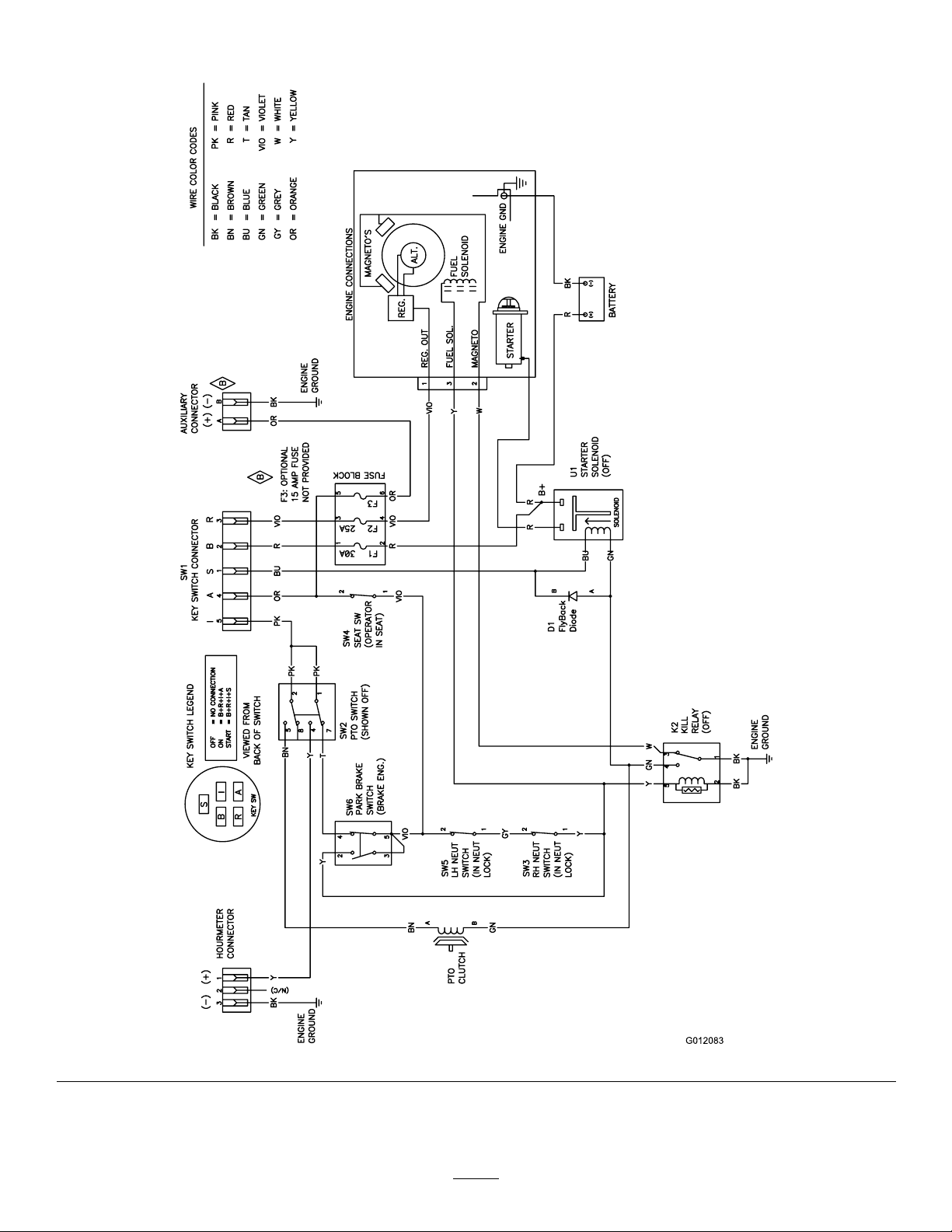
Schematics
G012083
WireDiagram(Rev.A)
51
Page 52

TheToroTotalCoverageGuarantee
AThree-Y earLimitedWarranty
TITANMowers
ConditionsandProductsCovered
TheToro®Companyanditsafliate,T oroWarrantyCompany ,pursuantto
anagreementbetweenthem,jointlypromisetorepairanyToroProduct,if
defectiveinmaterialsorworkmanshipfortheperiodlistedbelow.
ThisWarrantyappliestoallTIT ANMowersandtheiraccessories.
Thiswarrantycoversthecostofpartsandlabor,butyoumustpay
transportationcosts.
Thefollowingtimeperiodsapplyfromthedateofpurchase:
ProductsWarrantyPeriod
TITANMowers
-Frame
-Engine
Attachments(foraboveunits)3yearsor240hours*
Batteries1year
Warrantymaybedeniedifthehourmeterisdisconnected,altered,or
showssignsofbeingtamperedwith.
3yearsor240hours*
Lifetime(originalowneronly)**
3yearsor240hours*
OwnerResponsibilities
YoumustmaintainyourT oroProductbyfollowingthemaintenance
proceduresdescribedintheOperator’sManual.Suchroutine
maintenance,whetherperformedbyadealerorbyyou,isatyourexpense.
ItemsandConditionsNotCovered
Thereisnootherexpresswarrantyexceptforspecialemissionsystem
coverageandenginewarrantycoverageonsomeproducts.Thisexpress
warrantydoesnotcoverthefollowing:
•Costofregularmaintenanceserviceorparts,suchaslters,fuel,
lubricants,oilchanges,sparkplugs,airlters,bladesharpening/worn
bladeonmowers,cable/linkageadjustments,orbrakeandclutch
adjustments
•Componentsfailingduetonormalweararenotcoveredbythis
warranty
•Anyproductorpartwhichhasbeenalteredormisusedandrequires
replacementorrepairduetoaccidentsorlackofpropermaintenance
•Repairsnecessaryduetoimproperbatterycare,failuretousefresh
fuel(lessthanonemonthold),orfailuretoproperlypreparetheunit
priortoanyperiodofnon-useoveronemonth
•Pickupanddeliverycharges
•Operationalmisuse,neglect,oraccidents
•RepairsorattemptedrepairsbyanyoneotherthananAuthorized
ToroServiceDealer
InstructionsforObtainingWarrantyService
IfyouthinkthatyourT oroProductcontainsadefectinmaterialsor
workmanship,followthisprocedure:
1.ContactanyAuthorizedT oroServiceDealertoarrangeserviceattheir
dealership.Tolocateadealerconvenienttoyou,refertotheYellow
Pagesofyourtelephonedirectory(lookunder“LawnMowers”)or
accessourwebsiteatwww.Toro.com.Y oumayalsocallthenumbers
listedinitem#3tousethe24-hourToroDealerlocatorsystem.
2.Bringtheproductandyourproofofpurchase(salesreceipt)tothe
ServiceDealer.Thedealerwilldiagnosetheproblemanddetermine
ifitiscoveredunderwarranty.
3.IfforanyreasonyouaredissatisedwiththeServiceDealer’s
analysisorwiththeassistanceprovided,contactusat:
CustomerCareDepartment,ConsumerDivision
ToroW arrantyCompany
811 1LyndaleAvenueSouth
Bloomington,MN55420-1196
Tollfreeat866-216-6029(U.S.customers)
Tollfreeat866-216-6030(Canadiancustomers)
GeneralConditions
Allrepairscoveredbythesewarrantiesmustbeperformedbyan
AuthorizedToroServiceDealerusingT oroapprovedreplacementparts.
RepairbyanAuthorizedT oroServiceDealerisyoursoleremedyunder
thiswarranty .
NeitherTheToro®CompanynorToroWarrantyCompanyisliablefor
indirect,incidental,orconsequentialdamagesinconnectionwiththe
useoftheToroProductscoveredbythesewarranties,includingany
costorexpenseofprovidingsubstituteequipmentorserviceduring
reasonableperiodsofmalfunctionornon-usependingcompletionof
repairsunderthesewarranties.
Allimpliedwarrantiesofmerchantability(thattheproductistfor
ordinaryuse)andtnessforuse(thattheproductistforaparticular
purpose)arelimitedtothedurationoftheexpresswarranty.
Somestatesdonotallowexclusionsofincidentalorconsequential
damages,orlimitationsonhowlonganimpliedwarrantylasts,sothe
aboveexclusionsmaynotapplytoyou.
Thiswarrantygivesyouspeciclegalrights,andyoumayalsohaveother
rightswhichvaryfromstatetostate.
CountriesOtherthantheUnitedStatesorCanada
CustomerswhohavepurchasedT oroproductsexportedfromtheUnitedStatesorCanadashouldcontacttheirT oroDistributor(Dealer)toobtain
guaranteepoliciesforyourcountry ,province,orstate.IfforanyreasonyouaredissatisedwithyourDistributor’sserviceorhavedifcultyobtaining
guaranteeinformation,contacttheToroimporter.Ifallotherremediesfail,youmaycontactusatT oroWarrantyCompany .
*Whicheveroccursrst.
**LifetimeFrameWarranty-Ifthemainframe,consistingofthepartsweldedtogethertoformthetractorstructurethatothercomponentssuchastheenginearesecuredto,
cracksorbreaksinnormaluse,itwillberepairedorreplacedunderwarrantyatnocostforpartsandlabor.Framefailuresduetomisuseorabuseandfailureorrepair
requiredduetorustorcorrosionarenotcovered.
374-0258RevA
 Loading...