

Page 1
ZeroTurnRadiusMowers
Allmodels
LooseParts
Usethechartbelowtoverifythatallpartshavebeenshipped.
FormNo.3359-833RevA
SetupInstructions
ProcedureDescription
Deectorassembly
7
8
Note:Determinetheleftandrightsidesofthemachinefromthenormaloperatingposition.
Rod1
Spring
IgnitionKey1
Hosecoupling1
Operator’sManual
EngineOperator’sManual
OperatorTrainingMaterial
Qty.
1
1
1
1
1
Verifythatlanyardisfreetorotateonbothendsso
thatitpullsstraightwhilesupportingtheseat.
1
CheckingTirePressure
NoPartsRequired
Procedure
Use
Installthedischargedeector
CompletetheSetup.
1.Checkthetirepressureinthedrivetires.Proper
inationfordrivetiresis13psi(90kPa).
2.Adjustifnecessary.
2
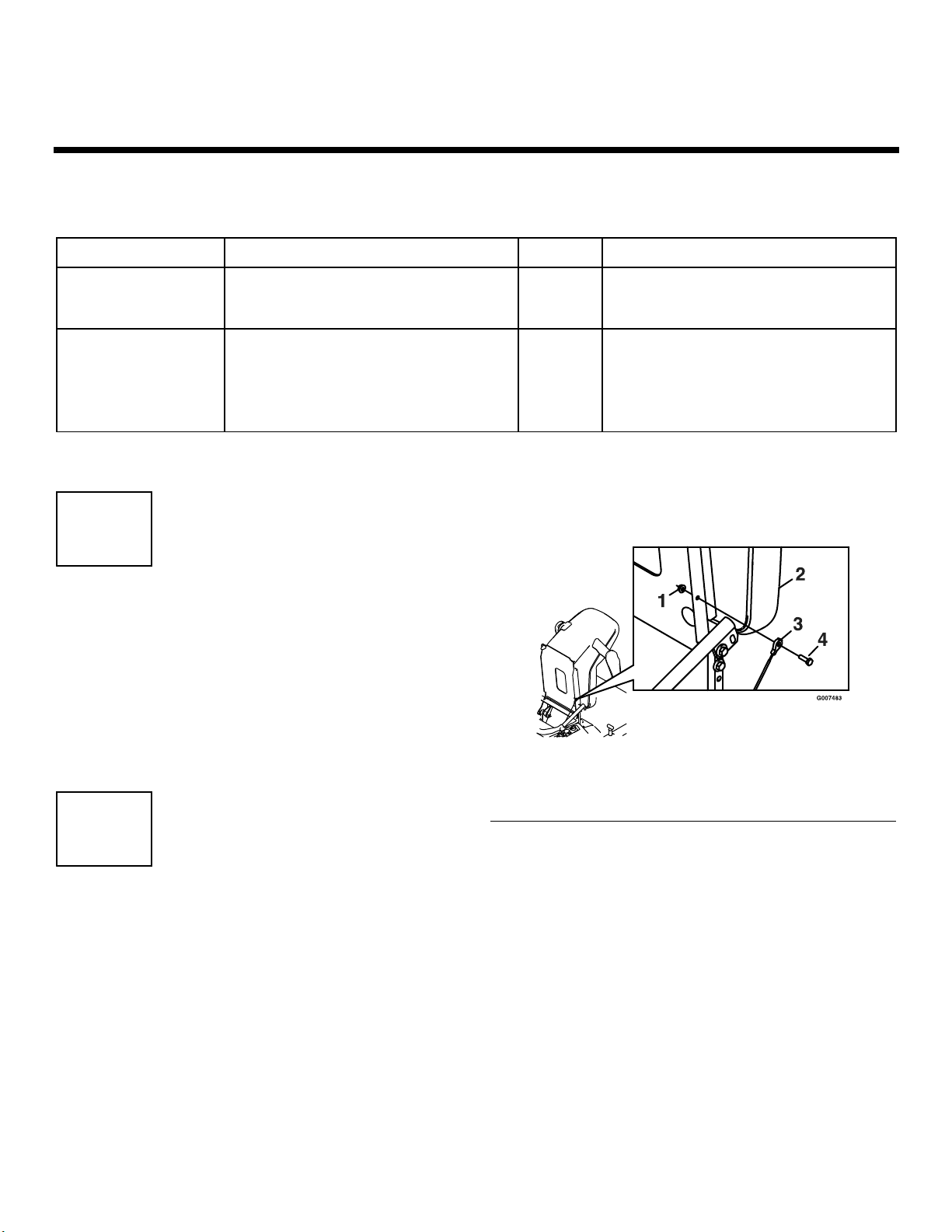
FasteningtheSeat
NoPartsRequired
Procedure
1.Removethenutandboltfromthelooseendofthe
lanyard.
2.Tiltseatdownwardandalignlanyardtotheholein
thesideoftheseat(Figure1).
3.Installboltandnut.Tightenboltandthenloosen
nut1/4-1/2turnsothatlanyardendrotatesfreely.
Figure1
1.Seatassembly3.5/16-18inchwhizlocknuts
2.Seattrackstuds
PrintedintheUSA.OriginalInstructions(EN)
AllRightsReserved
Page 2
3
ServicingtheBattery
NoPartsRequired
Procedure
Warning
CALIFORNIA
Proposition65Warning
Batteryposts,terminals,andrelated
accessoriescontainleadandleadcompounds,
chemicalsknowntotheStateofCalifornia
tocausecancerandreproductiveharm.
Washhandsafterhandling.
Important:Themachineisshippedwithalled
leadacidbattery.
Voltage
Reading
12.6or
greater
12.4–12.6
12.2–12.4
12.0–12.2
11.7–12.0
11.7orless
Percent
Charge
100%16volts/7
75–100%16volts/7
50–75%16volts/7
25–50%14.4volts/4
0–25%14.4volts/4
0%14.4volts/2
Maximum
Charger
Settings
amps
amps
amps
amps
amps
amps
Charging
Interval
NoCharging
Required
30Minutes
1Hour
2Hours
3Hours
6Hoursor
More
Iftheignitionisinthe“ON”positionthere
ispotentialforsparksandengagementof
components.Sparkscouldcauseanexplosion
ormovingpartscouldaccidentallyengage
causingpersonalinjury
1.Tiltseatuptogainaccesstothebattery.
Chargingthebatterymayproduceexplosive
gasses.Batterygassescanexplodecausing
seriousinjury.
•Keepsparks,ames,orcigarettesawayfrom
battery.
•Ventilatewhenchargingorusingbatteryin
anenclosedspace.
•Makesureventingpathofbatteryisalways
openoncebatteryislledwithacid.
2.Checkthevoltageofthebatterywithadigital
voltmeter.Locatethevoltagereadingofthebattery
inthetablebelowandchargethebatteryforthe
recommendedtimeintervaltobringthechargeup
toafullchargeof12.6voltsorgreater.
Important:Makesurethenegativebattery
cablesaredisconnectedandthebatterycharger
usedforchargingthebatteryhasanoutputof
16voltsand7ampsorlesstoavoiddamaging
thebattery(chartforrecommendedcharger
settings).
Besureignitionswitchisinthe“OFF”position
beforechargingthebattery.
3.Connectthenegativebatterycables.
Note:Ifthepositivecableisalsodisconnected,
connectthepositive(red)cabletothepositive
batteryterminalrst,thenthenegative(black)cable
tothenegativebatteryterminal.Slipinsulatorboot
overthepositiveterminal.
Note:Iftimedoesnotpermitchargingthebattery,
orifchargingequipmentisnotavailable,connect
thenegativebatterycablesandrunthevehicle
continuouslyfor20to30minutestosufciently
chargethebattery.
4
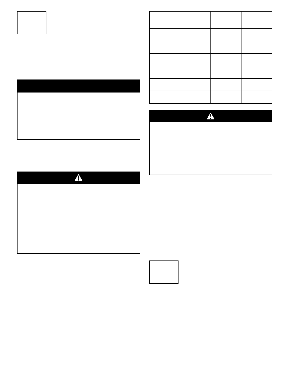
InstallingtheMotionControl
Levers
NoPartsRequired
Procedure
1.Removethebottom3/8x1inchboltandspring
discwasherfromthecontrolarmshaft.Loosenthe
2
Page 3
upper3/8x1inchboltandspringdiscwasherinthe
controlleversothatthelevercanrotate(Figure2).
bendingthemoutward.Movethembacktothedrive
positionandcheckforclearance.Repeatifnecessary.
2.Positiontheleversothebottomholealignswith
holeinthecontrolarmshaft.Installspringdisc
washerandbolt.
3.Repeatonoppositesideofunit.
Note:Therearetwoleverheightoptionsavailable.
Placetheleversinthetoptwoholestoincrease
heightofthelevers,orinthebottomtwoholesto
decreasetheheightofthelevers.
Figure2
1.Bolt
2.Springdiscwasher5.Controlarmshaft
3.Motioncontrollever
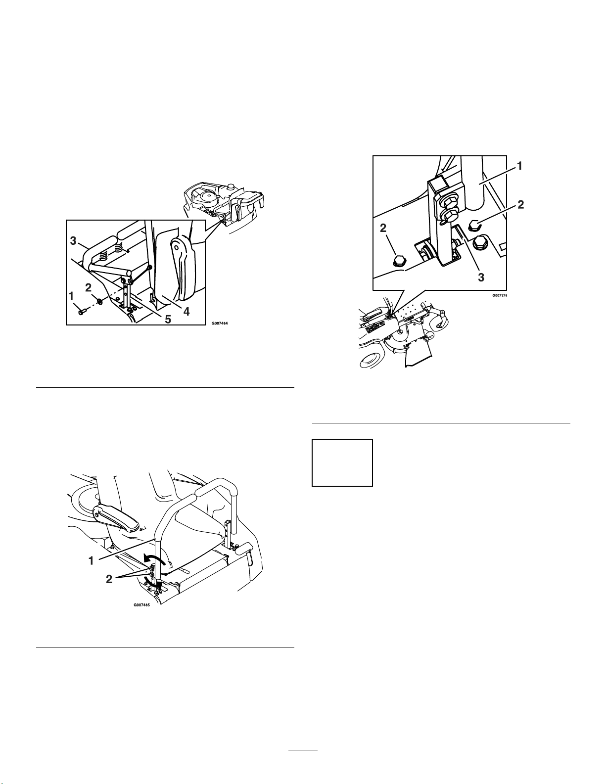
4.Aligntheleversfront/rearposition.Withthelevers
intheneutralposition,loosenthehardwareand
adjusttheleversslidingand/ortiltingthelever(s)
forwardorbackwarduntilproperlyalignedand
tightenhardware(Figure3).
4.Seat
6.Ifthemachineturnsrightorleftwhenhandlesare
pushedforwardtogether,adjustthestopontheside
oppositethedirectionofturn(Figure4).Loosen
thescrewsthatholdthemotioncontrollimiterstop.
Movethestopbackuntiltheunitdrivesstraight.
Tightenthescrewstolockthestopinplace.Readjust
handlesifnecessary.
Figure4
1.Controlarmshaft
2.Limiterstopscrews
3.Adjuststop
Figure3
1.Motioncontrollever2.Hardware
5.Iftheendsofthelevershitagainsteachother,
whileinthedriveposition(leversrotatedinasfaras
possible),makeadjustmentsbymovingthelevers
outwardstotheneutrallockpositionandcarefully
5
ServicingtheEngine
NoPartsRequired
Procedure
Engineisshippedwithoil;checkoillevelandif
necessarylltotheappropriatelevelwithoilasspecied
inEngineOwner’sManual.
3
Page 4

6
G006036
1
2
3
4
5
7
ServicingtheHydraulicOil
NoPartsRequired
Procedure
Themachineisshippedwithhydraulicoil.Verifylevel
onExpansionTank(Figure5).
1.Startengineanddrivethemachineforwardand
backwardforafewminutestoallowanyextraairto
purgeoutofthehydraulicsystem.
2.Stopengineandwaitforallmovingpartstostop.
Removekeyandengageparkingbrake.
3.CheckexpansiontankandifnecessaryaddMOBIL1
15W-50syntheticmotoroiltotheFULLCOLDline.
Note:Theproperamountofoilshouldhavebeen
addedatthefactory.Ifthereservoirisslightlyover
full,DoNotremoveuid.Thelevelwillgodown
oncealloftheairispurgedfromthesystem.
InstallingtheDischarge
Deector
Partsneededforthisprocedure:
1
Deectorassembly
1Rod
1
Spring
Procedure
1.Positionthedischargedeectorassemblywiththe
bracketendsbetweentheweldedbracketsonthe
deckasshowninFigure6.
1.Engine2.Expansiontank
4.Replaceexpansiontankcapandtightenuntilsnug.
DoNotovertighten.
Figure5
1.Deectorassembly4.Spring
2.Deckbrackets
3.Rod
2.Installthespringontothestraightendoftherod.
PositionthespringontherodasshowninFigure6
sotheshorterspringendiscomingfromunderthe
rodbeforethebendandgoingovertherodasit
returnsfromthebend.
4
Figure6
5.Springinstalledoverthe
rod
Page 5

3.Installthespringandrodassemblythroughthe
G006049
1
2
3
4
openingsinboththedeckbracketsandthedeector
bracket(Figure6).
4.Liftthelongendofthespringandplaceitintothe
notchonthedeectorassemblybracket(Figure7).
5.Securetherodandspringassemblybytwistingitso
theshortendoftherodcanbeplacedbehindthe
frontbracketweldedtothedeck(Figure7).
8
CompletingtheSetup
Partsneededforthisprocedure:
1IgnitionKey
1Hosecoupling
1
Operator’sManual
1
EngineOperator’sManual
1
OperatorTrainingMaterial
CheckingtheMowerAdjustment
Themowerdeckwasleveledatthefactory.Ifthemower
isnotcuttinglevel,adjusttheside-to-sidelevelandthe
front-to-rearbladeslope.SeetheOperator’sManualfor
theproperprocedure.
Figure7
1.Rodandspringassembly
partiallyinstalled
2.Longendofthespring
installedintothenotchin
thedeectorbracket
3.Rod,shortend,moved
behindmowerbracket
4.Shortend,retainedby
mowerbracket.
Important:Thedischargedeectormustbe
springloadedinthedownposition.Liftthe
deectoruptotestthatitsnapstothefulldown
position.
ReviewtheRemainingParts
Keepallthefollowingitemswiththemachine:
•IgnitionKey
•Hosecoupling
•Operator’sManual
•EngineOperator’sManual
•ViewtheOperatortrainingmaterial.
5
Page 6

Page 7

Page 8

 Loading...